Embed Size (px)
Citation preview
Rule of Thumb 2
Steam Turbines 2-3
RMS Capabilities 4
RMS Welcomes 5
10th Anniversary 6
37th Turbomachinery Symposium
6
Booths
54 & 756
The Finish Line Phone 484-821-0702 Fax 484-821-0710 www.rotatingmachinery.com
������
VOLUME 4, ISSUE 1
June 2007—June 2008
What’s Inside
ROTATING MACHNERY SERVICES, INC.
Rotating Machinery Services had a record sales year in 2007. We have been in our new office and shop complex since May ‘07. Currently, plans are underway to further expand the office and shop. We have increased our staff in 2008 to continue to bring our customer the same level of individual attention that you have come to know from RMS.
Exciting things are happening at RMS, as we are currently execut-ing several multi-million dollar projects, entrusted to us by our customers. We look forward to helping all our customers solve their turbomachinery problems bringing about high levels of per-formance and reliability.
On behalf of RMS, I wish all our customers and suppliers the very best in 2008.
Regards,
Neal J. Wikert
RMS RECEIVED INC 5000 AWARD
On August 23, 2007, Inc. ranked Rotating Machinery Services No. 540 on its first-ever Inc. 5,000 list of the fastest-growing private companies in the country.
The Inc. 5,000, an extension of Inc. Magazine’s annual Inc. 500 list, catches many businesses that are too big to grow at the pace required to make the Inc. 500, as well as a host of smaller firms. Taken as a whole, these compa-nies represent the backbone of the U.S. economy.
The 2007 Inc. 5000 list measures revenue growth from 2003 through 2006. To qualify, com-panies had to be U.S.-based and privately held, independent – not subsidiaries or divisions of other companies.
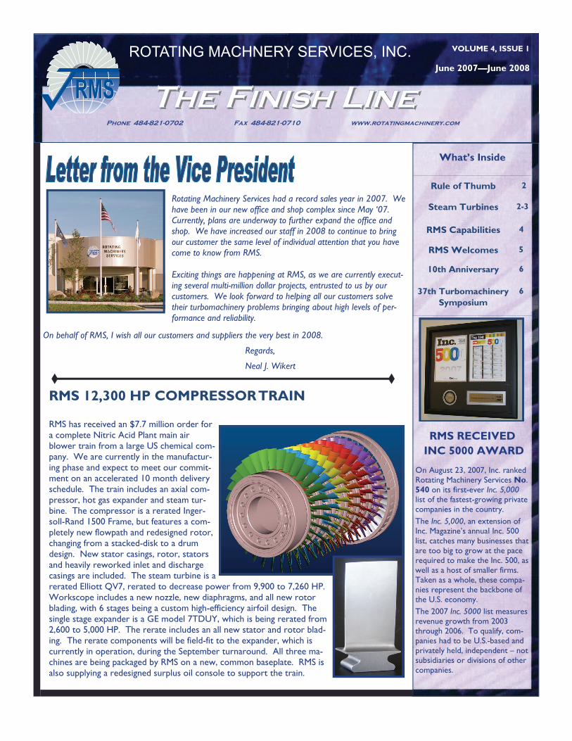
RMS 12,300 HP COMPRESSOR TRAIN
RMS has received an $7.7 million order for a complete Nitric Acid Plant main air blower train from a large US chemical com-pany. We are currently in the manufactur-ing phase and expect to meet our commit-ment on an accelerated 10 month delivery schedule. The train includes an axial com-pressor, hot gas expander and steam tur-bine. The compressor is a rerated Inger-soll-Rand 1500 Frame, but features a com-pletely new flowpath and redesigned rotor, changing from a stacked-disk to a drum design. New stator casings, rotor, stators and heavily reworked inlet and discharge casings are included. The steam turbine is a rerated Elliott QV7, rerated to decrease power from 9,900 to 7,260 HP. Workscope includes a new nozzle, new diaphragms, and all new rotor blading, with 6 stages being a custom high-efficiency airfoil design. The single stage expander is a GE model 7TDUY, which is being rerated from 2,600 to 5,000 HP. The rerate includes an all new stator and rotor blad-ing. The rerate components will be field-fit to the expander, which is currently in operation, during the September turnaround. All three ma-chines are being packaged by RMS on a new, common baseplate. RMS is also supplying a redesigned surplus oil console to support the train.
������ Page 2 ROTATING MACHINERY SERVICES, INC.
RULE OF THUMB - FCC EXPANDER—START UP PROCEDURE By Neal Wikert
PRESTART CHECK OUT
1. Review instruction manuals for all train components 2. Verify that all train components have been properly aligned and that all couplings and guards have been properly installed.
3. Check all oil reservoirs to ensure adequate oil supply. All oil drain lines should have been flushed by this time. Verify lube oil flow to the bear-ing compartment of each component.
4. Verify casing drains on all components are open and clear.
5. Check low spots in air and steam piping are clear of accumulated water prior to startup.
6. Verify that electric power, air, water, and steam are available to the various system components. Turn on buffer air to bearing housing seals and adjust air pressure to minimize vent misting.
7. Verify that all inlets are clear of debris and foreign objects.
8. Perform functional check on all control equipment. Exercise all controlled positioned (nonmanual) valves to verify functionality. Verify that all temperature and vibration instruments are operational and calibrated.
9. Verify all alarm and shutdown switches are properly set.
10. Set solenoid trip, turbine trip valve and over speed trip mechanism. Ensure all valves are positioned for unit start.
AXIAL COMPRESSOR
1. Verify drains at the intake and discharge casings are open. Compressor and discharge flow meter pressure sensors and temperature indicators should have been calibrated by this time.
2. Verify that the inlet throttle valve is functioning. Set initial valve position at full open.
3. Verify the variable stator vane actuation system is functioning properly. Set initial vane angle at 0 degrees setting.
STEAM TURBINE 1. Open steam turbine and piping drains to drain condensate.
2. Close turbine throttle valve and open bypass valve to atmosphere.
3. Blow down steam line by initiating steam flow through the turbine supply piping and out bypass. Progressively close piping drain valves once dry steam flow is established. Continue piping warmup until the bypass pipe temperature has stabilized at 650 deg. F. or above.
EXPANDER
1. Verify drains at the intake and discharge casings are open.
2. Blow down steam cooling supply lines at the connection to the piping on the expander.
3. Close the expander inlet valve and fully open the bypass valve.
Steam Turbine Seals By Sydney Gross In the previous issue we discussed the various types of steam turbine stage designs, i.e., Curtis, Rateau and reaction, and the distribution of pres-sure drops or amount of reaction across those stages. Pressure differences are fundamental to all turbomachinery. It is therefore critical to performance to effectively isolate regions of different pressure since we know from Bernoulli that fluids will flow in the direction of decreasing pressure gradient. The challenges in sealing tur-bomachinery include consideration of rotating and stationary parts and their associated clear-ances as well as material compatibility and rela-tive thermal growth. The following paragraphs are a general discussion of how seals work and the various types of seals in a steam turbine.
Although there are several seal designs that em-ploy such mechanisms as disc pumping and the inclined plane in the form of screw type threads to impede the leakage of fluids, this discussion
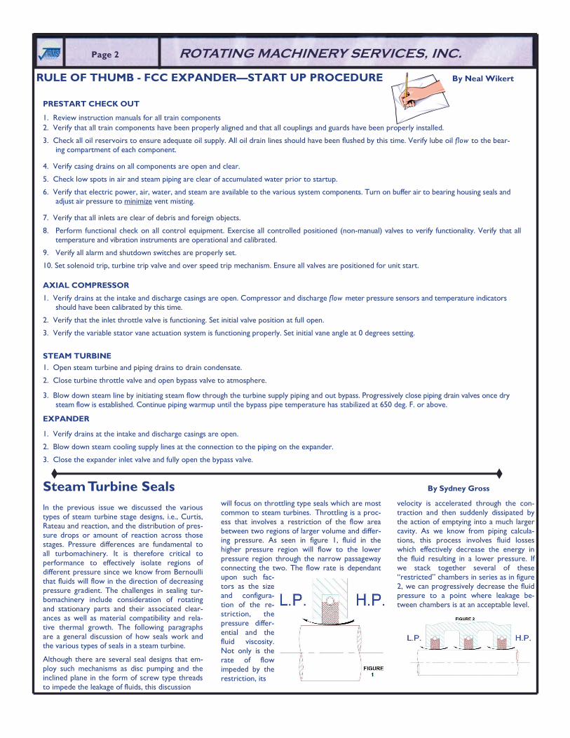
will focus on throttling type seals which are most common to steam turbines. Throttling is a proc-ess that involves a restriction of the flow area between two regions of larger volume and differ-ing pressure. As seen in figure 1, fluid in the higher pressure region will flow to the lower pressure region through the narrow passageway connecting the two. The flow rate is dependant upon such fac-tors as the size and configura-tion of the re-striction, the pressure differ-ential and the fluid viscosity. Not only is the rate of flow impeded by the restriction, its
velocity is accelerated through the con-traction and then suddenly dissipated by the action of emptying into a much larger cavity. As we know from piping calcula-tions, this process involves fluid losses which effectively decrease the energy in the fluid resulting in a lower pressure. If we stack together several of these “restricted” chambers in series as in figure 2, we can progressively decrease the fluid pressure to a point where leakage be-tween chambers is at an acceptable level.
Steam Turbine Seals (con’t) By Sydney Gross
Carbon rings are exactly that, rings made of Carbon. They “float” on the shaft due to their large OD clearance to the casing. They are also very soft compared to steel so that a rub will wear the carbon rather than the shaft. For these reasons, a Carbon ring can have very close clearance and pro-vide an excellent seal. Typical Carbon ring seal clearances are such that the Carbon ring ID is 0.0015” per inch shaft diameter larger than the shaft. However because it is soft, it is limited to approximately 15 psid and shaft speeds of approximately 200 ft/sec. Otherwise the steam flow will rapidly erode the Carbon. Also, because they are fragile, they are found on the shaft ends where they can be accessed without significant disassembly of the turbine. Carbon rings are typically split in 3 sections with a garter spring encircling the segments to hold them together.
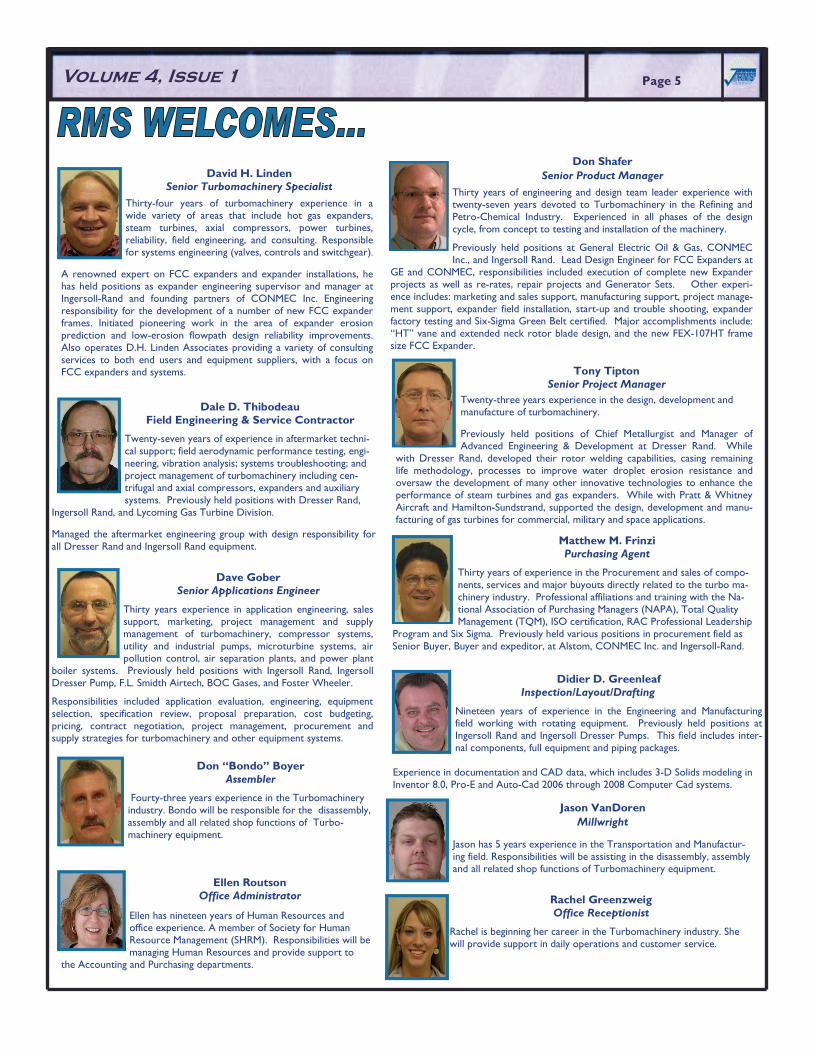
Labyrinth seals are typically made of bronze, stainless steel or Ni-resist depending on conditions. Because they are harder and not as rub tolerant as Carbon, they do not operate with such tight clearances. Typical laby-rinth clearances are in the range of 0.001” to .002” radial per inch of shaft diameter. They do not provide as effective a seal as Carbon rings but have a pressure drop limit of 4 to 6 times Carbon. In higher pressure differential applications, one will normally find stepped or high-low type labyrinth seals as shown in figure 5. The steps provide a more tortuous path for the steam and are more effective than straight through labyrinths. Stepped labyrinths are typically used on the high pressure shaft end seals and in the dia-phragms on the high pressure end of the turbine. Stepped labyrinth seals, while more effective than straight through labyrinths, complicate the axial alignment of the rotor. Where differential axial growth between rotor and casing is significant, as in the exhaust end of the turbine, stepped labyrinths may not be practical.
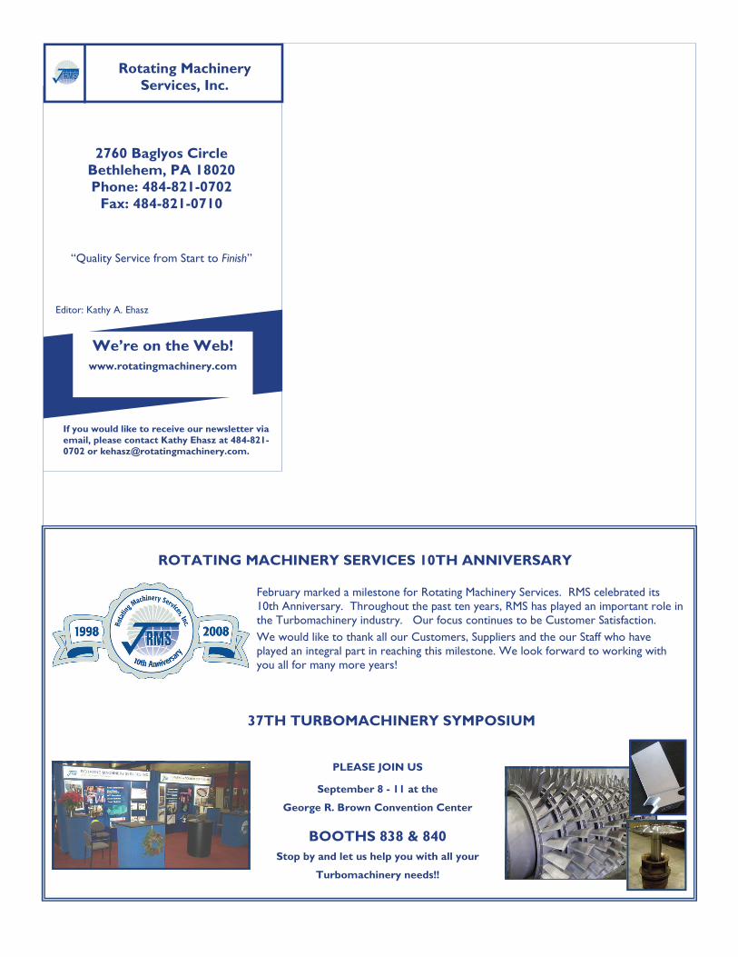
Another type of seal which has gained popularity in steam applications is the brush seal, long a staple of the gas turbine industry. The brush seal is constructed of many small diameter, tightly packed wire bristles, typically stainless steel, sandwiched in an outer ring. The bristles point inward to-ward the shaft at an angle off radial (see figure 6). They can be floating or fixed, maintain a tight clearance akin to Carbon seals, are rub tolerant, durable, and are not limited in pressure differential. They are currently available as “drop-in” retrofits on some smaller turbines and can be applied with engineering in areas where Carbon rings have proved troublesome.
So, where does the steam go that leaks out the shaft ends? In the upcom-ing issue we will answer that question when we discuss seal arrangements and systems for shaft end seals in steam turbines.
������Page 3 Volume 4, Issue 1
One may ask, why not decrease the area of the restriction to a point where leakage is acceptable with only one throttling. The answer is that the restriction must be formed between a rotating and a station-ary component where contact is not acceptable lest serious damage be done to the equipment. Therefore, minimum clearances are dic-tated by manufacturing and assembly tolerance, vibration displace-ment levels especially transient, and rub tolerance.
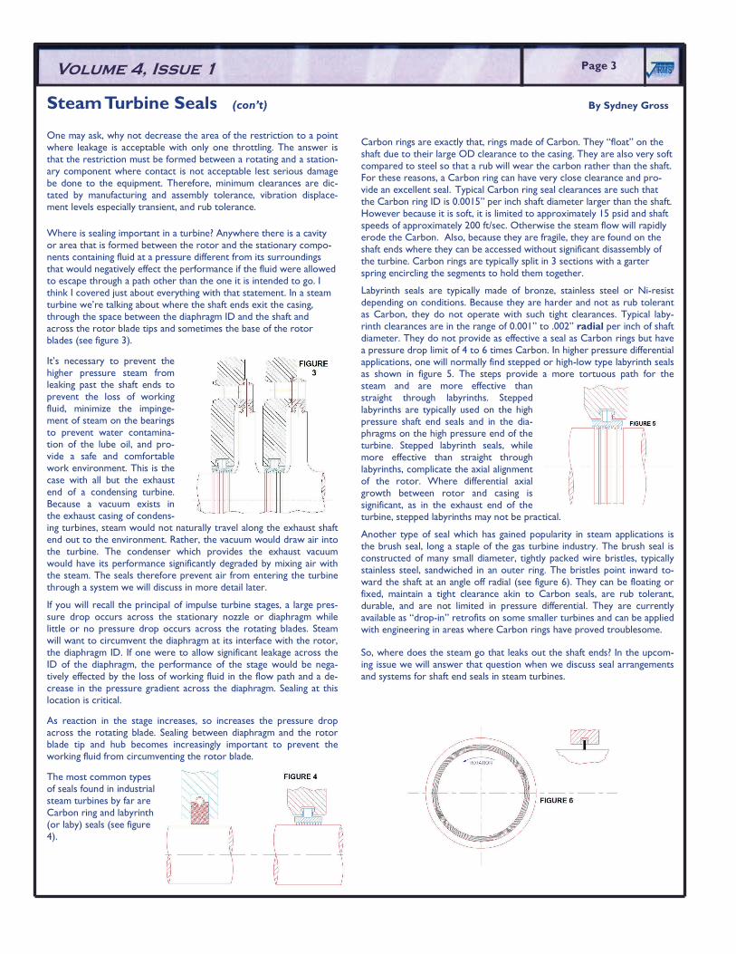
Where is sealing important in a turbine? Anywhere there is a cavity or area that is formed between the rotor and the stationary compo-nents containing fluid at a pressure different from its surroundings that would negatively effect the performance if the fluid were allowed to escape through a path other than the one it is intended to go. I think I covered just about everything with that statement. In a steam turbine we’re talking about where the shaft ends exit the casing, through the space between the diaphragm ID and the shaft and across the rotor blade tips and sometimes the base of the rotor blades (see figure 3).
It’s necessary to prevent the higher pressure steam from leaking past the shaft ends to prevent the loss of working fluid, minimize the impinge-ment of steam on the bearings to prevent water contamina-tion of the lube oil, and pro-vide a safe and comfortable work environment. This is the case with all but the exhaust end of a condensing turbine. Because a vacuum exists in the exhaust casing of condens-ing turbines, steam would not naturally travel along the exhaust shaft end out to the environment. Rather, the vacuum would draw air into the turbine. The condenser which provides the exhaust vacuum would have its performance significantly degraded by mixing air with the steam. The seals therefore prevent air from entering the turbine through a system we will discuss in more detail later.
If you will recall the principal of impulse turbine stages, a large pres-sure drop occurs across the stationary nozzle or diaphragm while little or no pressure drop occurs across the rotating blades. Steam will want to circumvent the diaphragm at its interface with the rotor, the diaphragm ID. If one were to allow significant leakage across the ID of the diaphragm, the performance of the stage would be nega-tively effected by the loss of working fluid in the flow path and a de-crease in the pressure gradient across the diaphragm. Sealing at this location is critical.
As reaction in the stage increases, so increases the pressure drop across the rotating blade. Sealing between diaphragm and the rotor blade tip and hub becomes increasingly important to prevent the working fluid from circumventing the rotor blade.
The most common types of seals found in industrial steam turbines by far are Carbon ring and labyrinth (or laby) seals (see figure 4).
PRODUCTS: • Axial Compressors • Centrifugal Compressors • FCC Expanders • Nitric Acid Expanders • Steam Turbines • Gas Turbines • Power Turbines • Packaged Trains
SERVICES: • Machinery Inspections • Training • Field Service Supervision • Train Alignment • Source Inspections
SUPPORT: • Turnaround Support • Power Generation • Steel Industries • Gas Transmission • Refining • Chemical
MAIN OFFICE: 484-821-0702 · SALES OFFICE: 281-340-8520 · www.rotatingmachinery.com
Page 5 ������Volume 4, Issue 1 Page 5 ������
Tony Tipton Senior Project Manager
Twenty-three years experience in the design, development and manufacture of turbomachinery.
Previously held positions of Chief Metallurgist and Manager of Advanced Engineering & Development at Dresser Rand. While
with Dresser Rand, developed their rotor welding capabilities, casing remaining life methodology, processes to improve water droplet erosion resistance and oversaw the development of many other innovative technologies to enhance the performance of steam turbines and gas expanders. While with Pratt & Whitney Aircraft and Hamilton-Sundstrand, supported the design, development and manu-facturing of gas turbines for commercial, military and space applications.
Matthew M. Frinzi Purchasing Agent
Thirty years of experience in the Procurement and sales of compo-nents, services and major buyouts directly related to the turbo ma-chinery industry. Professional affiliations and training with the Na-tional Association of Purchasing Managers (NAPA), Total Quality Management (TQM), ISO certification, RAC Professional Leadership
Program and Six Sigma. Previously held various positions in procurement field as Senior Buyer, Buyer and expeditor, at Alstom, CONMEC Inc. and Ingersoll-Rand.
Don Shafer Senior Product Manager
Thirty years of engineering and design team leader experience with twenty-seven years devoted to Turbomachinery in the Refining and Petro-Chemical Industry. Experienced in all phases of the design cycle, from concept to testing and installation of the machinery.
Previously held positions at General Electric Oil & Gas, CONMEC Inc., and Ingersoll Rand. Lead Design Engineer for FCC Expanders at
GE and CONMEC, responsibilities included execution of complete new Expander projects as well as re-rates, repair projects and Generator Sets. Other experi-ence includes: marketing and sales support, manufacturing support, project manage-ment support, expander field installation, start-up and trouble shooting, expander factory testing and Six-Sigma Green Belt certified. Major accomplishments include: “HT” vane and extended neck rotor blade design, and the new FEX-107HT frame size FCC Expander.
Dave Gober Senior Applications Engineer
Thirty years experience in application engineering, sales support, marketing, project management and supply management of turbomachinery, compressor systems, utility and industrial pumps, microturbine systems, air pollution control, air separation plants, and power plant
boiler systems. Previously held positions with Ingersoll Rand, Ingersoll Dresser Pump, F.L. Smidth Airtech, BOC Gases, and Foster Wheeler.
Responsibilities included application evaluation, engineering, equipment selection, specification review, proposal preparation, cost budgeting, pricing, contract negotiation, project management, procurement and supply strategies for turbomachinery and other equipment systems.
Didier D. Greenleaf Inspection/Layout/Drafting
Nineteen years of experience in the Engineering and Manufacturing field working with rotating equipment. Previously held positions at Ingersoll Rand and Ingersoll Dresser Pumps. This field includes inter-nal components, full equipment and piping packages.
Experience in documentation and CAD data, which includes 3-D Solids modeling in Inventor 8.0, Pro-E and Auto-Cad 2006 through 2008 Computer Cad systems.
Don “Bondo” Boyer Assembler
Fourty-three years experience in the Turbomachinery industry. Bondo will be responsible for the disassembly, assembly and all related shop functions of Turbo-machinery equipment.
Jason VanDoren Millwright
Jason has 5 years experience in the Transportation and Manufactur-ing field. Responsibilities will be assisting in the disassembly, assembly and all related shop functions of Turbomachinery equipment.
Dale D. Thibodeau Field Engineering & Service Contractor
Twenty-seven years of experience in aftermarket techni-cal support; field aerodynamic performance testing, engi-neering, vibration analysis; systems troubleshooting; and project management of turbomachinery including cen-trifugal and axial compressors, expanders and auxiliary systems. Previously held positions with Dresser Rand,
Ingersoll Rand, and Lycoming Gas Turbine Division.
Managed the aftermarket engineering group with design responsibility for all Dresser Rand and Ingersoll Rand equipment.
David H. Linden Senior Turbomachinery Specialist
Thirty-four years of turbomachinery experience in a wide variety of areas that include hot gas expanders, steam turbines, axial compressors, power turbines, reliability, field engineering, and consulting. Responsible for systems engineering (valves, controls and switchgear).
A renowned expert on FCC expanders and expander installations, he has held positions as expander engineering supervisor and manager at Ingersoll-Rand and founding partners of CONMEC Inc. Engineering responsibility for the development of a number of new FCC expander frames. Initiated pioneering work in the area of expander erosion prediction and low-erosion flowpath design reliability improvements. Also operates D.H. Linden Associates providing a variety of consulting services to both end users and equipment suppliers, with a focus on FCC expanders and systems.
Rachel Greenzweig Office Receptionist
Rachel is beginning her career in the Turbomachinery industry. She will provide support in daily operations and customer service.
Ellen Routson Office Administrator
Ellen has nineteen years of Human Resources and office experience. A member of Society for Human Resource Management (SHRM). Responsibilities will be managing Human Resources and provide support to
the Accounting and Purchasing departments.
2760 Baglyos Circle Bethlehem, PA 18020 Phone: 484-821-0702
Fax: 484-821-0710
“Quality Service from Start to Finish”
We’re on the Web! www.rotatingmachinery.com
Rotating Machinery Services, Inc.
������
If you would like to receive our newsletter via email, please contact Kathy Ehasz at 484-821-0702 or [email protected].
Editor: Kathy A. Ehasz
ROTATING MACHINERY SERVICES 10TH ANNIVERSARY
February marked a milestone for Rotating Machinery Services. RMS celebrated its 10th Anniversary. Throughout the past ten years, RMS has played an important role in the Turbomachinery industry. Our focus continues to be Customer Satisfaction.
We would like to thank all our Customers, Suppliers and the our Staff who have played an integral part in reaching this milestone. We look forward to working with you all for many more years!
37TH TURBOMACHINERY SYMPOSIUM
PLEASE JOIN US
September 8 - 11 at the
George R. Brown Convention Center
BOOTHS 838 & 840 Stop by and let us help you with all your
Turbomachinery needs!!