Embed Size (px)
Citation preview

������������� ��� ��������������� ����
Johan Källström
LiTH-ISY-EX-31922001-11-05


������������� ��� ��������������� ����
Examensarbete utfört i Fordonssystemvid Linköpings Tekniska Högskola
av
Johan Källström
Reg nr:LiTH-ISY-EX-3192
Handledare: Robert R. Newberry, Ingemar AnderssonExaminator: Lars Nielsen
Linköping 2001-11-05


5
�������������������
Division, department
Department of Electrical Engineering
���������������
Date 2001-11-05
�� !
Language
❑ Svenska/Swedishx Engelska/English
❑ ______________
"���� #�
Report: category
❑ Licentiatavhandlingx Examensarbete❑ C-uppsats❑ D-uppsats❑ Övrig rapport
ISBN
ISRN
Serietitel och serienummer$�������� ���������� ���
ISSN
LiTH-ISY-EX-3192%"&�' ����! ����!��� ����www.fs.isy.liu.se
$�������������������� �����������������������������������Title Embedded software for new engine controller
(' �� ��)�*���+,��� '�Author Johan Källström
�����������Abstract
This thesis describes software development for and testing of a new prototyping system for engine controlunits used at DaimlerChrysler. The system uses advanced new hardware to implement the enginecontroller. The purpose of the new hardware is to reduce the cost for the development of new enginecontrol units without sacrificing performance. This is achieved by using hardware designed specifically forengine control. With the help of advanced software tools it should also be possible for people withoutdetailed knowledge about the hardware or programming to work with the system during development.
The development of drivers for the hardware and a communication protocol to allow communicationbetween the ECU and external units is presented. An application to allow engineers to performmeasurements and calibrations during the development of the engine controller is also assembled andtested. It should be possible for people without knowledge about programming the system to use and alterthis application.
The testing shows that the current system is functioning satisfactory, but it is also concluded thatmodifications might have to be made in the future when the engine controller is expanded to perform morefunctions. It is also concluded that some modifications to the software could be made to increase theperformance of the system. It is believed that the described development system will be very powerfulonce it has matured.
-#�!��� �Keywords ECU, embedded system, vehicular system, rapid prototyping
01-1
1-05


��������This thesis describes software development for and testing of a new prototyping system for
engine control units used at DaimlerChrysler. The system uses advanced new hardware to
implement the engine controller. The purpose of the new hardware is to reduce the cost for
the development of new engine control units without sacrificing performance. This is
achieved by using hardware designed specifically for engine control. With the help of
advanced software tools it should also be possible for people without detailed knowledge
about the hardware or programming to work with the system during development.
The development of drivers for the hardware and a communication protocol to allow
communication between the ECU and external units is presented. An application to allow
engineers to perform measurements and calibrations during the development of the engine
controller is also assembled and tested. It should be possible for people without knowledge
about programming the system to use and alter this application.
The testing shows that the current system is functioning satisfactory, but it is also concluded
that modifications might have to be made in the future when the engine controller is expanded
to perform more functions. It is also concluded that some modifications to the software could
be made to increase the performance of the system. It is believed that the described
development system will be very powerful once it has matured.
�������� !�"����I would like to thank my supervisor Robert Newberry and everyone else at DaimlerChrysler
in Esslingen for their help. Special thanks to Frank at AIEC for his help on the hardware and
the engine controller, which made work much easier.
Linköping, November 2001
Johan Källström


�����#$��$���
ADW ARM Debugger for WindowsAIEC Automotive Integrated Electronics CorporationAPIC ARM Processor Interrupt ControllerARM Advanced RISC MachinesASIC Application Specific Integrated CircuitAXD ARM eXtended DebuggerCAN Controller Area NetworkECU Engine Control UnitFPGA Field Programmable Gate ArrayGUI Graphical User InterfaceICE In-Circuit EmulatorIDE Integrated Development EnvironmentISR Interrupt Servicing RoutineIRQ Interrupt RequestKWP2000 Keyword Protocol 2000LED Light Emitting DiodeLLIB Load/Logic Interface BoardPWM Pulse Width ModulatorRISC Reduced Instruction Set ComputerRTEC Real-Time Engine ControllerSCI Serial Communication InterfaceSOC System On Chip


1
�./-$�-$��
����-$"/�%.$�/-������������������������������������������������������������������������������������������������������������������
�0���1�.+2"/%-� ��0���/1)�.$�3�� 4�05��"����"6��2%��� 7
���$8����3�&/9:�-$��;�$�:���������������������������������������������������������������������������������������<
�0���/3�"3��=�/(�$8����3�&/9:�-$��;�$�: <�0���"��&�$�:��=/"+�8/9 ���05���":���3�&/9�"��%�$� ���0>��:%&$���.� �5�0���$8���":�9"/.���/"�1/�"� �5�04��$8���-$�2"�$/"�&/2�.�:/�%&� ���07��&/��?&/2�.��-$�"(�.��1/�"� �@�0@��$8���-2�-��./-$"/&&�" �<�0<��./::�-$��/-�$8����3�&/9:�-$��;�$�: �<
5��9"/2"�::�-2�$8���-2�-��./-$"/&&�"���������������������������������������������������������
50����/($=�"����3�&/9:�-$�(/"���1�"��1/�"���-3�"/-:�-$ ��50���.?.AA�3�"�%������:1&;�&�-2%�2� ��505���/($=�"����3�&/9:�-$�(/"�$8��"��&�$�:���-2�-��./-$"/&&�" �550>����$$�-2�%9��-��$��$�-2�$8����3�&/9:�-$��;�$�: ��
>��$8���":�9"/.���/"��-$�""%9$�./-$"/&&�"����������������������������������������������7
>0����-(/":�$�/-��1/%$�$8���9�. �7>0����-�$��&���$�/-�/(�$8���;�$�: �<>05��$��$�-2�$8���9�.�(%-.$�/-�&�$; 5�>0>��./::�-$��/-�$8���9�.��-��$8����3�&/9���"/%$�-�� 5�
���$8����"��&�./::%-�.�$�/-��-$�"(�.����������������������������������������������������������5�
�0����-(/":�$�/-��1/%$�$8���.� 5��0�����3�&/9�-2�"/%$�-���(/"�$8���.� 5��05����3�&/9����"�3�"��(/"�$8���.� 57�0>��./--�.$�/-�$/�$8��9. 5<�0����3�&%�$�/-�/(�$8���.��"/%$�-�� >��04��./::�-$��/-�$8����3�&/9����.��"/%$�-�� >�

2
4��$8��+�;=/"��9"/$/./&�������������������������������������������������������������������������������������>5
40�����(�-�$�/-�/(�+=9���� >540����:9&�:�-$�$�/-�/(�$8��9"/$/./& >�405��$��$�-2�/(�$8��9"/$/./&�=�$8�9.�$�":�-�&�9"/2"�: >@40>��./::�-$��/-�$8���:9&�:�-$�$�/-�/(�+=9���� ��
7�����9$�-2�+=9�����$/�:�".�����������������������������������������������������������������������������������5
70���$8��:�".���99&�.�$�/-��;�$�: �570���:/��(�.�$�/-��:����$/�$8��9"/2"�: �>705����:�".���99&�.�$�/-��B�:9&� �770>��$��$�-2�$8���99&�.�$�/- 4�70���./::�-$��/-����9$�-2�+=9�����$/�:�".� 4�
@��./-.&%��/-���-���%22��$�/-��(/"�$8��(%$%"���������������������������������������45
@0���$8����3�&/9����/($=�"� 45@0����%22��$�/-��(/"�(%"$8�"���3�&/9:�-$ 45@05���3�&%�$�/-�/(�$8����3�&/9:�-$��;�$�: 4�@0>��./-.&%��/-� 4�
"�(�"�-.���������������������������������������������������������������������������������������������������������������������������47
�99�-��B��C�31�./���������������������������������������������������������������������������������������������������������4<
�99�-��B�1C�"��5��./-3�"$�"���$���8��$��������������������������������������������������������77

3
�&��$�/(�(�2%"���FIGURE 1: THE DEVELOPMENT SYSTEM AND ITS COMPONENTS _____________ 9FIGURE 2: THE ARM EXTENDED DEBUGGER _______________________________ 12FIGURE 3: THE ARM PROCESSOR BOARD __________________________________ 14FIGURE 4: THE ARCHITECTURE OF THE INTEGRATOR LOGIC MODULE ______ 16FIGURE 5: PRODUCING A BITSTREAM FOR THE FPGA ______________________ 17FIGURE 6: DOWNLOADING A BITSTREAM TO THE FPGA ____________________ 18FIGURE 7: BLOCK SCHEDULE OF THE LLIB ________________________________ 18FIGURE 8: BLOCK SCHEDULE OF THE REAL-TIME ENGINE CONTROLLER ____ 23FIGURE 9: BLOCK SCHEDULE OF THE APIC ________________________________ 27FIGURE 10: THE APIC REGISTERS _________________________________________ 28FIGURE 11: THE SCI REGISTERS___________________________________________ 36FIGURE 12: SCHEMATIC FOR THE RS232 CONVERTER_______________________ 39FIGURE 13: FORMAT FOR A KWP2000 REQUEST MESSAGE __________________ 43FIGURE 14: FORMAT FOR A KWP2000 POSITIVE RESPONSE __________________ 44FIGURE 15: FORMAT FOR A KWP2000 NEGATIVE RESPONSE_________________ 44FIGURE 16: FLOWCHART FOR KWP2000____________________________________ 46FIGURE 17: COMPONENTS OF THE KWP2000 PROGRAM _____________________ 47FIGURE 18: EXAMPLE OF A COMMUNICATION LOG FILE____________________ 49FIGURE 19: THE USER INTERFACE OF THE TERMINAL PROGRAM____________ 50FIGURE 20: A MARC1 DEVELOPMENT ENVIRONMENT ______________________ 54FIGURE 21: FORMAT FOR KWP2000 MESSAGES_____________________________ 55FIGURE 22: THE BITS OF THE FORMAT BYTE_______________________________ 55FIGURE 23: THE TIMING OF RESPONSE MESSAGES _________________________ 56FIGURE 24: LOOK-UP TABLES IN MARC1 __________________________________ 59

4

5
%��$�����&'����This thesis describes work carried out on DaimlerChrysler’s new development system for
engine control units, ECU:s. The work was carried out at DaimlerChrysler’s research and
development department in Esslingen, Germany. This chapter gives a short introduction to the
problem that was to be solved and also gives a reader’s guide to the thesis.
������������ DaimlerChrysler in Esslingen has recently started working on a new system for ECU
development. The centre of the system is a real-time engine controller developed by AIEC,
Automotive Integrated Electronics Corporation. This engine controller is implemented using a
processor core provided by ARM, Advanced RISC Machines. For the development of control
algorithms Matlab and Simulink are used, and with the help of Real-Time Workshop these
algorithms can be transformed to embeddable C code. This way fast and efficient
development of engine control functions can be performed. When development is finished,
the engine controller will be fabricated as a System On Chip, SOC.
The first ECU:s started appearing in cars sometime in the mid 1970’s. There
were two main reasons for this. Firstly the high priced fuel had created a need to lower the
fuel consumption. Secondly the allowed emission rates had been lowered, forcing car
manufacturers to think of ways to reduce emissions from their engines. This could be done
with the aid of an ECU, which enabled a more accurate control of engine functions than
previously used mechanical methods. These mechanical methods had involved, among other
things, step up converters for the car battery creating thousands of volts, mechanical
”distributors” for choosing the right sparkplug and other crude methods. Scientists knew that
this was bad for power and pollutants. To achieve better results it would be necessary to
develop new technology to make it possible to more accurately mix fuel and air and ignite at
the right moment. It was easily understood that this could not be achieved by using the
mechanical devices, and interest soon turned to microprocessors.
The purpose of the ECU is to precisely mix air and fuel, and then ignite this mixture at
exactly the right moment. It is also possible to monitor the engine and diagnose unexpected

1 Introduction
6
and unwanted events. This information can then be used for service of the engine. For the
ECU to be able to work properly it is necessary to use sensors, measuring data critical to the
engine’s function. Examples of data needed to be measured are crank- and camshaft rotational
position, throttle position and rate of throttle position change. Before the input from the
sensors in the engine can be processed, it must be converted to digital form. To perform the
analogue to digital conversion the ECU is equipped with a number of A/D converters.
Communication is done with Controller Area Network, CAN, communication busses, which
provide fast and reliable communication in the tough automotive environment. For a
presentation of the theory of automotive control systems the reader is referred to (Kiencke &
Nielsen, 2000).
More advanced engine control functions soon demanded more powerful software for
calculations, which in turn raised the demands on the microprocessors used for the ECU:s.
For really sophisticated diagnostic functions it can be said that they need about the same CPU
usage as the engine controller. One disadvantage with microprocessors provided by some
manufacturers is that they are general-purpose in nature, and therefore might not be very well
suited for everybody’s specific needs. The reason for semiconductor manufacturers to
produce general-purpose devices is that they can be used for many different applications,
which means that the manufacturer can achieve a more cost efficient development and
production.
For the customer on the other hand, the effect can be quite the opposite. The general-purpose
microprocessors can not offer optimal performance for every specific task, and to compensate
for this it might be necessary to consider investing in more advanced, and therefore more
expensive, microprocessors. By using a peripheral that is specifically aimed towards engine
control applications it is possible to achieve high performance at a lower cost. It might also be
possible to implement functions that would be unthinkable when using a general-purpose
device. This has been one of the main design goals when developing the DaimlerChrysler
real-time engine controller, RTEC.
���������������The objectives of the work described in this thesis were to develop software that was needed
for the engine control unit and the development system described above. This software could
include drivers for the various engine control functions, I/O routines and routines needed for

1.3 Reader’s guide
7
the automatic code generation from the Matlab environment. At the department there is
currently a development system using a power PC based ECU. With this system it is possible
to use Simulink to design control structures and have C code for the ECU automatically
generated. Graphical environments for measurements and calibrations of the ECU can also be
generated from the Simulink environment. This means that people without knowledge about
hardware and programming can work with the system. It is desired to develop the software for
a similar system using the ARM hardware to implement the ECU.
Work came to focus on the implementation and testing of a communication protocol, keyword
protocol 2000 (KWP2000), which is used at DaimlerChrysler for communication between an
ECU and a diagnostic tool or another ECU, using RS232 serial communication.
Since the development system is brand new and has not previously been used at
DaimlerChrysler in Esslingen, some of the work would also include setting up and testing the
system and some of the functions of the engine controller.
�������� ������� �As a guide to the contents of this document, the following short summary of the chapters is
given:
• Chapter 2 describes the various parts of the development system that was used during the
work.
• Chapter 3 provides some information about things worth knowing when performing
software development for the RTEC.
• Chapter 4 presents the ARM Processor Interrupt Controller, APIC, how it works and what
initialisations have to be done for interrupt handling to function correctly. It also describes
how the APIC was used for the implementation of interrupt driven serial communication
on the system.
• Chapter 5 describes the Serial Communication Interface, SCI, that is implemented in the
engine control system and some drivers developed for it to be used for the implementation
of a communication protocol.
• Chapter 6 describes how the communication protocol KWP2000 is defined and how it
was implemented and tested.

1 Introduction
8
• Chapter 7 describes how the implementation of the protocol was slightly changed to work
correctly with a software tool used for ECU measurements and calibrations, and also gives
an example of how it was tested.
• Chapter 8 finally gives some conclusions and suggestions on how work could proceed in
the future.

9
(���)��������*�����������This chapter gives a short introduction to the various parts of the development system. The
system consists of hardware provided by ARM and AIEC for the implementation of the
engine controller, a power electronics board for connection to the engine and software tools
for development of control functionality.
������������������� ����������� ����The development system and its various components are shown in figure 1 below.
Simulink/RTW C/C++ IDE
C code
Sof
twar
e����
���
SW/H
W in
terf
ace
����
���
ECU VHDL model
Multi-ICE unit
Har
dwar
e��������
�������
Engine
Power electronics board
LLIB
Logic module
Processor boardSensor signals
Control signals
Synthesis tool
FPGA bitstream
�������������� ����������������������������������

2 The development system
10
The advanced hardware used in the system has been designed specifically for controlling
DaimlerChrysler engines, which should make it possible to develop high performance ECU:s
at a low cost. The processor board, the logic module and the LLIB are used to implement the
ECU by programming them with a synthesised VHDL model. The ECU will later be
implemented as a SOC. The software tools should make it possible to develop and test engine
control functions as fast as possible, without knowing any details about how the ECU is
programmed. This is accomplished by using Real-Time Workshop to automatically generate
the code needed for the system. The code is downloaded to the system with the Multi-ICE
unit. A description of each part of the development system is given in the following sections
of this chapter. To fully understand what is presented it might be useful for the reader to have
a basic knowledge about digital electronics and computer architecture. For a description of
application specific integrated circuits (ASIC), field programmable gate arrays (FPGA) and
digital electronics in general the reader is referred to (Schilling & Belove, 1989). In (Roos,
1995) a presentation of computer architecture, like for instance reduced instruction set
computers (RISC) can be found.
Since both software and hardware are quite sophisticated, a lot of time had to be spent getting
familiar with the equipment before work could really begin.
���������!�����"����Real-Time Workshop (RTW) is a software tool that is to be used together with Matlab and
Simulink. Simulink provides an environment where control algorithms can be implemented
and simulated in a fast and simple way. By using some of the available toolboxes for Matlab
development can be performed even faster. When a control function has been implemented
and tested in Simulink it is possible to use Real-Time Workshop to transfer the Simulink
model to ANSI C code, thereby making it possible to, for example, download it to a
microprocessor system as shown in the figure above.
A rapid prototyping system like this shortens the time needed for development. Since not as
much time has to be spent on writing code by hand, the engineer can concentrate on
developing and refining the important control algorithms. It is usually necessary to make
changes to the algorithms several times during development, and then perform testing to see if
the desired performance can be reached. For this kind of iterative design procedure a
development system using Real-Time Workshop can be ideal.

2.3 ARM Developer Suite
11
The code that is generated can be affected by choosing between a number of different target
templates, depending on what your needs are. If none of the available standard templates are
considered suitable the user has the option to design a custom template. This way it is
possible to have code generated that will give as high performance as possible when running
on the system in question.
�����#�$�%�������&����ARM is a semiconductor manufacturer offering microprocessors and a number of
development tools. Among other things they were the ones who developed the world’s first
commercial RISC processor (in 1985). The ARM developer suite, ADS, is a software package
that has been designed for developing applications for ARM based systems. The ADS has the
following features:
• Code generation tools with embedded C++ and C compilers, assembler and linker
• Code Warrior Integrated Development Environment (IDE) for Windows or UNIX
• Enhanced GUI debuggers (AXD and ADW)
• Instruction set simulators
• Support for new ARM cores
• On-line documentation
• ARM applications library
• RealMonitor, which is a powerful software tool that can be used for debugging real-time
systems, which can sometimes be somewhat complicated
The ADS comes with two debuggers: ARM eXtended Debugger, AXD, and ARM Debugger
for Windows, ADW. For the work described in this report AXD was used. This is a tool that
can be used to monitor and control a program that is being executed on an ARM system. It is
also used for download of program code to the system. The debugger has various functions
that can be useful when testing the developed software. The programmer has access to
memory, registers and program variables. This can be useful for debugging, for instance to
check that each register contains the right value during program execution. Breakpoints can
be set to halt execution at points that are considered critical.

2 The development system
12
Figure 2 below shows the debugger GUI, and some of the available functions. To the left of
the picture there is a window showing the variables of the program currently running. The two
windows in the middle show the program C code and disassembly. Breakpoints are added
simply by double clicking a point in one of these two windows. The window in the bottom
right corner of the picture shows the memory contents of the system. This can be useful for
finding hardware functions that are not operating correctly, causing some memory locations
to contain the wrong values. To the left of the memory window is the command line interface.
This can, for instance, be used to write values to memory. During the work described in this
report the ARM electronics were used for development without a motherboard. For this kind
of development system a memory write (smem 0x1000000C 0x04, as seen in the figure) has
to be done before a program can be executed on the system. Otherwise the electronic boards
will still think that they are connected to a motherboard, and will therefore try to fetch
program code from the wrong memory location. This memory write can be performed
manually from the debugger or be put in a script that is executed automatically when the
debugger is started.
���������������������������������

2.4 Multi-ICE
13
With the ADS there is also a code development environment included, a special ARM version
of the CodeWarrior IDE from Metrowerks. This tool together with the compilers is used to
create code that is particularly suited to run on an ARM based system such as the one used for
this work. It comes with library functions that have been provided by ARM, as to make code
development as fast and efficient as possible. Creating applications is very simple, you just
add your code files to a project and compile. The IDE is connected to the debugger, so that a
program can be compiled, downloaded to the system and run right from the IDE.
To be able to download the program to the system and debug it a third software is needed, the
Multi-ICE server. This provides a connection between the debugger and the Multi-ICE box,
which will be described in the next section of this chapter. From the Multi-ICE server
interface a configuration file is loaded, or the server can be configured automatically. It is
then left running during the debugging of the program. It is also possible to reset the target
from the server interface.
It took some time to get used to all the functions of the software used. But once you get
familiar with the programs they are very easy to use and work really well. No real problems
or shortcomings of the software were discovered during work.
��'��$����!()*Multi-ICE is a JTAG-based In-Circuit Emulator (ICE). This unit, together with the Multi-ICE
server, is what makes debugging of the system possible. It is possible to perform debugging
of the embedded processor at maximum clock frequency, and on-chip debugging of multiple
ARM and mixed architecture devices is also possible. In addition to that you can also debug
slow or variable frequency designs and low voltage cores (down to one volt). The device
supports all the current ARM cores and has fast download and stepping speeds. The Multi-
ICE unit can be seen in figure 6, used for programming the FPGA:s on the circuit boards.
��+��,���#�$��������� ARM provides development platforms enabling flexible development of a number of different
systems. The ARM processor board can be used for developing as a standalone system,
together with an ARM Integrator motherboard or integrated into an ASIC prototyping system.
It is also possible to connect a number of boards (up to four) on top of each other to further
expand the system.

2 The development system
14
The board comes equipped with the following features:
• ARM966E-S microprocessor core
• Volatile memory comprising up to 256MB of SDRAM (optional) plugged into the DIMM
socket and 1MB SSRAM
• Core module FPGA which implements SDRAM controller, system bus bridge, reset
controller, interrupt controller, status- , configuration- and interrupt registers
• SSRAM controller PLD
• Clock generator
• Integrator system bus connectors
• Multi-ICE debug connector
• Logic analyser connectors for local memory bus
• Trace port
Figure 3 below shows how the ARM processor board looks and what different components
are on it (as described in the text above).
FPGA
Logic analyser connectorsSDRAM DIMM
connectors
Processor core
Core module/motherboard connectors
Trace connector
Multi-ICE connectorPower connector
Core module/motherboard connectors
Reset button
�������������������������������

2.6 The Integrator logic module
15
The core module/motherboard connectors, as shown in the figure, are used to stack a number
of boards or to connect the processor board to an ARM motherboard. For our system the
ARM processor board is used for development together with an ARM Integrator logic module
and a Load/Logic Interface Board, LLIB, which are described in the following two sections of
the report.
This is a very flexible development system, which allows for fast prototyping to be
performed. It is easy to implement and test new functions for applications. The real-time
engine controller used for our system has been specifically designed for use together with an
ARM core. This means that it has been possible to implement it in such a way that maximum
performance is reached. This is not always possible when building a control system using a
general-purpose microprocessor. When development is finished the ARM core and the RTEC
will be fabricated as a SOC.
��-��,���(������������� ���The Integrator/LM logic module is a device designed by ARM to be used as a platform when
developing systems using their ARM cores. The logic module can be used in four different
ways:
• As a standalone system.
• With an ARM processor board and Integrator motherboard.
• As a processor board with the Integrator motherboard if a synthesised core is programmed
into the FPGA on the board.
• Stacked without a motherboard with one module in the stack providing the same system
controller functions as a motherboard would.
Our system uses the last option, a stack with an ARM processor board, an Integrator logic
module and the LLIB. The implementation of the RTEC is located in the FPGA on the
Integrator logic module. It is possible to make modifications to the RTEC, for instance if an
error in the old implementation is discovered, and download this new implementation to the
FPGA. This is of course very practical when testing a new system.

2 The development system
16
Figure 4 below shows the architecture of the Integrator logic module, and what is available to
the developer. The board has basically the same connectors as the ARM processor board, to
allow connecting it to the Multi-ICE unit and logic analysis tools. It also has connectors to
make it possible to add the board to a board stack. For prototyping there is also a grid of
connections to the FPGA that is located on the board. This prototyping grid can be used to
access the inputs and outputs of the FPGA. It could for instance be used to:
• Wire to off-board circuitry.
• Mount connectors.
• Mount small components.
This possibility can be very useful when developing new systems, where for example
connections to off-board equipment of various kinds are necessary.
Oscillators
OSC1 OSC2
Connectors
Multi-ICE
Module/MotherboardTrace
Logic analyzer
Prototyping grid
LEDs
Switches
Pushbutton
FPGA
ZBTSSRAM
������� ������������������!�����"����������������������
The logic module FPGA can be programmed to perform different functions. With the help of
VHDL or Verilog a description of the logic in the FPGA for a certain functionality is created.
By using logic synthesis this description is turned into an Electronic Data Interchange Format,
EDIF, netlist that is technology specific (for instance to be used with Xilinx FPGA:s). Apart
from a VHDL/Verilog description you also have to provide the synthesis tool with
information about the technology you are using. The EDIF netlist is then combined with some
requirements on the design to produce a final output for the FPGA:s to be programmed with.

2.6 The Integrator logic module
17
Different software have different requirements and options, but the information you supply
the program with to perform the whole procedure usually contains the following:
• A list of HDL files.
• The target technology.
• Required optimisation.
• Timing and frequency requirements.
• Required pull-ups or pull-downs on the FPGA input/output pads.
• Output drive strengths.
For our system Xilinx hardware is used, and by using Xilinx specific software and the EDIF
netlist a bitstream file is generated. This file is then used for programming the FPGA:s. Figure
5 below shows the program flow when producing a new bitstream for the FPGA:s to be
programmed with.
HDLfile(s)
Synthesistool
Place androute tool
Constraintsfile
FPGAbitstream
EDIFnetlist
�������#�$���������������������!��������$%�
This programming procedure might have to be repeated several times before a fully
functioning and stable system has been achieved. The method is very efficient and allows for

2 The development system
18
fast development of new systems. The actual downloading to the FPGA:s is done with the
help of Multi-ICE by connecting it to the logic module as shown in figure 6 below.
The logic moduleThe Multi-ICE unitComputer runningthe Multi-ICE server
Parallellconnection
J-TAGconnection
08/7,���
ARM
�������&���'�����������������������������$%�
��.��/� 0/����(���������� The load/logic interface board, LLIB, is an interface board designed for prototyping SOC
integrated circuits. The primary function of the device is to provide an interface between a
load board with power electronics and a logic board with microprocessor and peripherals. The
3.3 volts used on the logic board are converted to 5 volts for the load board, and the other way
around. The LLIB is also equipped with A/D converters to handle the conversion of analogue
sensor signals from the load board to digital signals that can be handled by the logic board.
There are also two discrete CAN interface circuits for communication purposes. A maximum
of 152 signals can be transferred between the load and logic boards. This is controlled by
programming the FPGA:s on the LLIB. The pins on the board can be programmed as inputs,
outputs or bi-directional pins. The programming is done in the same way as for the integrator
logic module. A block schedule of the interface between load board and logic board is shown
in figure 7 below.
Digital Control Signals
Digital Control Signals
Digital Control Signals
Digital Control Signals
3.3V to 5V conversion
5V to 3.3V conversion
Loa
d bo
ard
conn
ecto
rs
A/D converters
CANsTX L
ogi
c bo
ard
conn
ecto
rs
RX
�������(�)���*�����������!�����++")

2.8 The engine controller
19
��1��,����������������The real-time engine controller has been developed by AIEC and it is available as a VHDL
model. By using the procedure described above the FPGA on the logic module can be
programmed with this model.
The RTEC is a peripheral that has been developed for use together with a microprocessor core
for controlling internal combustion engines. It was designed to increase the performance of
the engine and decrease the exhaust of pollutants by making a precise delivery of ignition and
injection pulses possible. By using an advanced design the interrupt handling performed by
the controlling processor has been reduced, giving a great increase in throughput. This in turn
makes it possible to use more complex control algorithms, since the processor can spend more
time on processing these.
Because of the intelligent hardware it is not necessary to write that many low level routines
for the drivers, which makes software development simpler, faster and cheaper. The fact that
the RTEC is not a general-purpose device but instead dedicated hardware gives high
performance at lower cost for the engine controller.
��2��)������������� ����������� ����Both the software and the hardware used during the work on this thesis are quite advanced
and complex. It was therefore necessary to do a lot of literature studies before the actual
software development could begin. Of course it also took some time to get used to the various
development programs and to learn to take advantage of their available features as much as
possible.
The hardware developed exclusively for DaimlerChrysler is very new and has not yet been
used that much. That meant that some problems appeared during work with the hardware not
acting exactly as you expected it to. This was usually due to the FPGA:s being programmed
with incorrect configuration files, and the solution was simply to have new configuration files
generated and downloaded to the circuit boards. Though not a very complicated procedure, it
was still somewhat time-consuming.

2 The development system
20

21
+���������������)���������'���������This chapter gives some information about what is worth considering when performing
software development for a real-time embedded system such as the RTEC. During such
software development it is necessary to take considerations not necessary when developing
for a computer platform like a PC environment. A real-time system is a system that must react
on certain events and deliver an appropriate response on time, while an embedded system is a
computer system that interacts with its environment. Some general information and some
information specific for the development performed on our system are given. A description of
software and hardware for embedded systems can be found in (Gupta, 1995). For a
presentation of real-time systems the reader is referred to (Burns & Wellings, 1997).
�����&������ �����������������!�� ����������When programming for a bare-board environment, that is a system where the processor is
working without the aid of an operating system, the programmer must have more knowledge
about how the system in question works. Some of the things that must be dealt with are the
I/O structure, interrupt structure and register set of the system. You also have to consider how
much program and data memory there is available on your system.
Access to external units like serial ports, A/D and D/A converters is performed by reading and
writing the control and data registers of these units. The programmer himself must make sure
that all the units are initialised in the right way before they are used. The functions available
in standard I/O library files like stdio.h and others can no longer be used, since standard I/O
does not work for an embedded application. Instead the programmer must write his own
version of the functions in these files that are needed for the system. The software tools that
come with ADS do however give the programmer the possibility to write messages to a
console window in the debugger, which can be useful for debugging.
When transferring old, non-embedded code, to an embedded application you might have to
consider what has been mentioned above. It is very possible that some changes have to be

3 Programming the engine controller
22
made for the code to be able to run on the embedded application, especially if it uses many
standard C library functions.
A short discussion on software development for bare-board environments and a good example
can be found in (Bilting & Skansholm, 2000).
�����)0)33�������������� ���������There are a number of factors that should be considered when choosing between doing
programming in assembly or in a high level language like C or C++. Some factors are
throughput, memory requirements, development schedules, portability and how experienced
the programmer is. For a real-time application it is often essential that the services are
performed as fast as possible.
A program written in assembly language will always be more efficient than a program written
in C, but the development time for the assembly code will most likely be longer than that for
the C code. When you start working with a new development system you might also have to
spend time learning the assembly instructions for that particular system, while most
programmers already have a good knowledge of C language. This means that if it is important
to get development started a soon as possible it might be better to use C as your programming
language, provided of course that it is possible to fulfil the requirements on the program when
coding in C.
A program written in C can also later on be ported to other systems, perhaps with some slight
modifications. A program written in assembly on the other hand can not be ported, but must
instead be completely rewritten. If modifications have to be made to the program in the future
by someone else than the original author it is also much easier to read and understand a
program written in a high level language.
When you try to optimise a program you will usually find that there are a few sections of the
code that take significantly more time to execute than others. Some say that a program spends
90% of the time in 10% of the code. One way to deal with optimisation could then be to write
these parts of the program in assembly, thus increasing system performance while not having
to spend too much time doing assembly coding.

3.3 Software development for the real-time engine controller
23
�����&������ �������������������!������������������The real-time engine controller that is used in the system is a sophisticated device developed
by AIEC. One of the objectives during the development of this device has been to put as
much functionality as possible in the hardware. The purpose of this is to obtain a system
where the developer has to spend as little time as possible writing drivers for the functions of
the engine controller, giving him more time to focus on developing control functions.
One of the goals has also been to make it possible to do all the driver development in a high
level language like C or C++. On some other systems it is often necessary to write drivers in
assembly to get high enough performance. By using intelligent hardware AIEC has made this
unnecessary when writing drivers for the RTEC. This means that the development can be
performed faster.
Figure 8 below is a block schedule of the RTEC that shows the various parts of the device, as
presented in (DCRTEC Reference Manual 0.2, 2001).
DataAddress
CRANKCAM
MicroprocessorInterface
Cam/CrankProcessor
Queued DataAcquisition UnitAnalogue
Inputs
Control
IgnitionChannels
InjectionChannels
Knock SignalsGenerator
Trigger
Vel
ocit
y b
us
Rea
l-ti
me
posi
tio
n b
us
IRQs
Injection Pu lses
Ignition Pulses
KCLKKW
LowResolutionProcessor
�������,�)���*�����������!���������-����������������������
The parts that the RTEC consists of are described below.
• The microprocessor Interface is responsible for monitoring the microprocessor control and
address lines and generating correct read and write signals to the RTEC registers.

3 Programming the engine controller
24
• The cam/crank processor keeps control of the cam and crank positions. It has got a
resolution of 0.1° after synchronisation. The synchronisation is done with the help of so
called teeth patterns.
• The queued data acquisition unit handles the A/D conversions. There are 32 analogue
inputs that are connected to a multiplexer. The conversion is performed using successive
approximation with 10-bit resolution, and can be position- or time-based-triggered or
initiated by software. After the initialisation of the queued data acquisition the conversions
are performed automatically, independently of the microprocessor.
• The ignition channels handle the task of asserting the ignition pins. They are programmed
by writing to two registers: the dwell time register and the ignition advance register. The
dwell time register decides when the pins are asserted and the ignition advance register
decides when the pins are de-asserted. The RTEC supports most of the ignition strategies
commonly used. After the two register writes have been performed, everything works
without disturbing the microprocessor.
• The knock signal generation is used for analysing knock intensity.
• The injector channels are used for implementing the chosen injection strategy. Most
commonly used strategies, like simultaneous injection, group injection and sequential
injection, are supported. After the initialisation the programming is done by register
writes. You can choose between angle/time mode (where an injector output pin is asserted
for a specified time starting at a programmed angle) or time/angle mode (where the output
pin is asserted at a programmed pulse time before the specified end angle).
• The low resolution processor has a resolution of 1.0° compared to the cam/crank
processor’s 0.1°. It can be used for starting A/D conversions at specified angles,
generating microprocessor interrupts at programmable engine positions and several other
functions. After the initialisation the low resolution processor works independently of the
microprocessor.
In addition to this engine control functionality there are also serial communication interfaces,
pulse width modulators, general purpose I/O and similar available for development.
Access to the different parts of the engine controller, as shown in the figure above, is
performed with memory-mapped registers. Driver development for the RTEC basically means
that you write to a number of different control registers to set the appropriate bits for a certain
function. By reading various status registers the software can control what is happening in the

3.4 Setting up and testing the development system
25
system, and thereafter take necessary actions. It is also possible to have interrupts generated
when flags are set. This can for instance be used to make sure that the system always handles
the most urgent task.
When declaring variables that should be used as flags or similar, it must be determined if
these variables can be changed by external devices, for instance in an interrupt routine. If that
is the case they should be declared with the keyword �������, like this (ready is a variable that
is changed when a flag in one of the status registers of the RTEC functions, for instance the
serial communication interface, is set):
�D� ������������ ready;
Otherwise the compiler might perform optimisations that will cause the program to operate in
the wrong way. The following while-loop, for instance, would not work if the variable ready
had not been declared as �������:
�*��� (!ready)
{
.…
}
If ready was not declared as �������, the program might only read the value of the variable
before the first turn of the loop, and then get stuck there forever. This sort of behaviour is
prevented by the use of the ������� keyword.
Since the registers of the RTEC are changed by external devices when various events occur,
the register variables should always be declared as �������.
��'��&������������ ������������� ����������� ����After the hardware and the software described in chapter two had been installed, some
software development was performed to make sure that the system was operating properly. A
second purpose of this was to get familiar with the tools that were to be used later on.

3 Programming the engine controller
26
The tools used are quite easy to get to know, and it does not take that long to get started with
the development. The programs have many useful features that proved very helpful for
debugging of programs that were not operating correctly.
Some simple programs were developed to test access to various registers of the system, for
instance general purpose I/O, LED:s and numeric displays. After this learning period, the
development of functions for the real engine control system was started, which is described in
detail in the following chapters.

27
,���)����"����'������$�����&*������������This chapter describes the ARM processor Interrupt Controller, APIC, and some routines that
were developed for it. Those routines were later to be used for implementing interrupt driven
serial communication on the system. Some information is also given about how the system
had to be initialised in order for the interrupt handling to work correctly. For a description of
how interrupt handling in computer systems works the reader is referred to (Roos, 1995).
'����(�����������������#4()The ARM processor itself does only provide two interrupt sources. For an engine control
system this is quite insufficient, since a lot of interrupts need to be generated by the different
sensors in the engine and handled simultaneously by the control system. To solve this
problem AIEC has developed the ARM Processor Interrupt Controller, which adds an
additional number of thirty interrupt sources to the system, thereby making it more capable of
handling the demands of engine control. These interrupt sources can be assigned to different
inputs on the development boards by reprogramming the FPGA:s. Among the sources
currently available are the SCI, the RTEC low resolution processor and the RTEC queued
data acquisition. The structure of the APIC is shown in the block schedule in figure 9 below.
Details about the APIC are presented in (APIC Reference Manual 0.2, 2001).
InterruptSources
AddressesControl
Microprocessor Interface(R/W Control)
Priority Levels
Interrupt Types
Interrupt Masks
ISR Addresses
Fast InterruptRouting
InterruptPriotizer/Arbiter
LoadSelect(4:0)
ISR Vector
FIRQ
IRQ
Data in
CLK
Dataout
�������.�)���*�����������!������$"/

4 The ARM Processor Interrupt Controller
28
For each interrupt source the programmer decides on what priority the source should have,
sets the address of the associated interrupt servicing routine, ISR, and decides if the source
should be used as a hardware or software interrupt source. A hardware interrupt is generated
when a flag in a status register of one of the RTEC functions is set, while a software interrupt
can be generated at any time by the program code by doing a write to the control register of
the software interrupt source. It is also possible to define an interrupt source as a fast
interrupt, FIRQ. When many interrupt sources are used in the system, some thought must be
put into assigning each source the right priority.
When an interrupt is generated the ISR address of the source is moved into the ISR vector
register of the APIC, while the program counter jumps to address 0x18. Located at address
0x18 is a branch to the address located in the ISR vector register. When the ISR vector
register is read by the processor the interrupt is cleared, so that the program will not
immediately jump back into the servicing routine after the interrupt has been handled.
It is very important, especially for a system with a lot of interrupts generated, that the
interrupt handling is done in an effective way. Effective interrupt handling means higher
throughput and gives the processor more time to work with the important engine control
functions. That way the system performance is increased. This is something that has been one
of the major objectives during the design of the APIC.
Figure 10 below shows the available registers and their contents, as presented in (ENCORE
Reference Manual 0.3, 2001).
��������0�����$"/����������

4.2 Initialisation of the system
29
Following below is a short description of each register, as presented in the (APIC Reference
Manual 0.2, 2001).
• APICCNTRL: This register contains the control bits for enabling the generation of
interrupts.
• APICISTAT: This status register shows what interrupt source is currently being handled
and the priority of this source.
• APICFCNTRL: This is a status and control register for the fast interrupt request, FIRQ.
• APICISRVEC: This register is loaded with the address of the interrupt servicing routine
of the interrupt source currently being handled.
• APICFISRVEC: This register contains the address of the interrupt servicing routine of the
fast interrupt source.
• APICEOI: This register should be written to at the end of the interrupt servicing routine to
signal to the APIC that the interrupt handling has finished.
• APICISRVA0 -> APICISRVA31: These registers contain the addresses of the interrupt
servicing routines of the available interrupt sources.
• APICISCTL0 -> APICISCTL31: These are the control registers for the available interrupt
sources.
'����(�������������������� ����In order for the interrupt handling to work properly it is necessary to make sure that no
information is lost when an interrupt is generated, and thereby guarantee that the program can
continue to execute when the interrupt has been serviced.
In (ARM Developer Suite Version 1.1 Developer Guide, 2000) two different ways to handle
interrupts are presented. The simplest way to do it is by using the E� F keyword in front of the
declarations of the interrupt servicing routines, like this:
� FE ���� interrupt_servicing_routine(����);
By doing this you will let the compiler know that this routine is for handling interrupts and
make it add code necessary for storing and restoring crucial registers before and after the
routine, so that the interrupts work properly. In addition to that, initialisations of the stack
space, stack pointers and other system functions needed for the interrupt handling will be

4 The ARM Processor Interrupt Controller
30
carried out. The problem with the E� F keyword is that it does not work for re-entrant
interrupts, that is, no interrupt must occur during the servicing of another interrupt. If this
would happen registers would be corrupted and the system would not work. This makes the
E� F keyword useless for our system, since an engine control system with many interrupt
sources definitely should be able to handle re-entrant interrupts.
When the E� F keyword is not used the programmer must use the second, slightly more
complicated method, which involves making sure that the system is set up in such a way that
everything will work once an interrupt occurs. This means that some initialisation code has to
be written and executed at the start of a program.
When writing programs for the ARM system it is possible to choose from a number of
different configuration options. Depending on what your needs are you might have to write
more or less complex code to initialise the system in the proper way. The initialisation
routines used for our system handle the initialisation of some system functions needed for the
interrupt handling. Basically this involves setting up the stack space and initialising the stack
pointers, which are used when an interrupt servicing routine is called. You must also initialise
some flags used by the system, and finally it is necessary to make sure that the memory
location 0x18 contains a branch to the address pointed to by the ISR vector register. Most of
the initialisations can not be made from C language, but must instead be written in assembly.
When more interrupt sources are added to the system, or when other changes are made, it
might be necessary to add more code to the initialisation routine, for instance to set up the
stack space for the handling of fast interrupt requests, FIRQ. It might also be important to
think about how the layout of the memory map will affect the performance of your system.
No matter what your system is there will have to be ROM containing executable code at the
address 0x0 after a reset. After that you could simply leave the ROM where it is, but to
achieve maximum performance it can be necessary to perform a remapping of the memory.
Our system, and engine control systems in general, rely on interrupts generated by sensor
signals from various vital parts of the engine. The current system has 18 different sources for
generation of hardware interrupts, and there are an additional 14 sources that can be used for
generating software interrupts or for adding more hardware interrupt sources in the future.
When more interrupt sources are used in the future it might be worth considering using one of
the ROM/RAM memory remaps that are described in (ARM Developer Suite Version 1.1

4.3 Testing the APIC functionality
31
Developer Guide, 2000) to speed up the interrupt handling. The code for this could then be
included in the initialisation function for the system.
The above described initialisations are what is needed for the handling of a single interrupt on
the system. To accomplish re-entrant interrupt handling the interrupt handler routine,
IRQ_handler, must contain assembly code that stores all the relevant registers before
executing the code tied to a particular interrupt, and then restores the same registers after the
handling of the interrupt is finished. The interrupt servicing routine, rtec_int_isr, which
contains the code to perform the tasks needed for the interrupt currently being handled can be
written in C language and branched to from within the assembly code. At the end of the
interrupt servicing routine any flags that caused the interrupt should be cleared and by writing
to the APIC End Of Interrupt (APICEOI) register the program should signal to the APIC that
the handling of the interrupt has finished, which means that a new interrupt can be handled.
Each interrupt source should have an interrupt servicing routine like this.
Before the interrupt sources of the system can be used, an assembly-macro has to be called to
enable the interrupt handling, by reading the cpsr flags and updating bit 7. There is a similar
macro that does the opposite, that is it disables the interrupt handling. This macro could be
used before a crucial segment of code that must not be interrupted by any of the interrupt
sources.
'����,�����������#4()������������ To make sure that the interrupt handling was working the way that it was supposed to, and to
test some interrupt servicing routines that had been written, some simple test programs were
created.
The following routines for the initialisation and handling of the interrupt sources were written
for the system:
• system_init: a function that does the necessary initialisations of the system for the
interrupt handling to work properly, as described above.
• init_interrupts_sci: a function used to initialise the interrupts needed for the serial
communication routines developed further on.
• enable_interrupts: function to enable the generation of interrupts.

4 The ARM Processor Interrupt Controller
32
• interrupt_status: function to check the current status of the interrupt handling.
• enable_interrupt_source: function used to enable and configure one of the interrupt
sources.
• generate_software_interrupt: function used to generate a software interrupt on one of the
interrupt sources.
For testing purposes the interrupt servicing routines for the available sources were made to
simply reset the source that had caused the interrupt and print a message to the screen. This
was used to determine that the interrupt handling and the interrupt sources were working like
they should.
During the testing of the APIC it was discovered that the interrupts were not cleared when the
APICISR was read. This meant that this had to be done manually to prevent the program from
immediately jumping back into the interrupt routine as soon as finished interrupt handling
was signalled by writing to the APICEOI register, thereby causing the program to stall. By
generating new configuration files for the FPGA:s this problem was later removed and the
APIC was from there on functioning the way it should.
For the development described in this report the interrupts were used for interrupt driven
serial communication, which was then used for the implementation of a communication
protocol. The APIC was used for generating hardware interrupts when a character was
received on the serial port. The interrupt servicing routine put the received characters in a
buffer and called various functions depending on what commands had been received. Another
interrupt source was used for generating software interrupts when a response to the received
commands was to be sent. For timing of the messages sent, an interrupt driven timer was also
implemented later on. This will be described further in the following chapters of the thesis.
'�'��)�������������#4()��� ����� ������ �������One of the advantages of the RTEC is that it has a lot of functionality built into the hardware
that would usually have to be handled by writing code. This means for instance that not much
low level code has to be written when developing drivers for the various functions of the
system. For interrupt handling though, some low level code is needed before the system
functions the way it should. This code is actually needed for the ARM hardware, and not for

4.4 Comments on the APIC and the developed routines
33
the RTEC itself. But since this code does not have to be changed that often, it does not cause
the developer that many problems.
For the work described here only a couple of the available interrupt sources were used.
Adding support for the rest of the RTEC interrupt sources simply involves writing the
interrupt servicing routine, rtec_int_isr, for each added source. This routine can be written in
C language. The assembly IRQ_handler code will look the same for each interrupt source and
can therefor be reused.
When more interrupt sources are added the developer will have to put more thought into
assigning each source the right priority. For this thesis only four interrupt sources were used,
which meant that it was not that difficult to decide which source should have the highest
priority.

4 The ARM Processor Interrupt Controller
34

35
-���)�������������&��'������$�����'�This chapter describes the RTEC Serial Communication Interface, SCI, and the development
of routines for the same. The previously developed APIC routines were used to implement
interrupt driven serial communication on the system. This was later to be used for the
implementation of a communication protocol that is used by DaimlerChrysler ECU:s. Some
information about how serial communication and communication with external units work
can be found in (Roos, 1995).
+����(�����������������&)(On the LLIB there is a 30-pin port for which different functions of the RTEC can be assigned.
For our system two of the pins of this port were assigned to one of the two SCI:s that are
implemented in the RTEC. These pins were to be used for serial communication with external
equipment, like for instance a normal PC serial port. Routines for the SCI were developed for
a couple of different purposes. Most of the routines were designed so that they could later be
used for the implementation of the Keyword Protocol 2000, a communication protocol used
by ECU:s with diagnostic capability. This implementation is described in chapter 6 of this
report.
The SCI is implemented using the Motorola standard serial interface format. It can be used in
byte mode or in buffered mode, where there is a 16 byte receive buffer and a 32 byte transmit
buffer. There are control registers for choosing Baud rate, word length and parity type as well
as enabling generation of various kinds of interrupts. There are also a couple of status
registers available to the user.
The SCI is described in detail in (QSCI Reference Manual, 2001).
+����%����������������������&)(Writing drivers for the SCI basically consists of accessing the proper register and setting
control bits in such a manner that the desired function is achieved. After the control bits have
been set the status registers are used to monitor the communication. The registers available

5 The Serial Communication Interface
36
for the SCI in our system and the bits of these registers are shown in figure 11, taken from
(ENCORE Reference Manual 0.3, 2001).
�������������1/"����������
Following below is a short description of each of these registers and how they are used, as
presented in (QSCI Reference Manual, 2001).
• SCI1DR: This is the data register used in byte mode. It is used as a receive register when
read and as a transmit register when written.
• SCI1SR: This is the register containing status bits for the communication when
communicating in byte mode. It contains flags to monitor transmission, reception, line
activities and message errors.
• SCI1CR: This is the control register of the SCI. It contains control bits to enable
transmission/reception, loop-back from transmit to reception buffer, choice of parity and
character length and enabling various interrupts.
• SCI1BRR: This register is used to set the Baud rate of the system, and must be written
before any communication can start. The register is written with a suitable Baud rate
divisor to obtain the desired Baud rate.
• QSCI1CR: This register controls the SCI when operating in buffered mode. It contains
bits to enable buffered mode and the generation of various interrupts.
• QSCI1BD: This register is written with a value to determine how much delay should be
inserted between transmitted bytes when operating in buffered mode. The delay is
measured in (system clock / 1024). A delay might be necessary when communicating with
slow devices.
• QSCI1SR: This register contains status bits for the buffered SCI. The bits show status of
transmit and receive buffers and the logic level of transmit and receive pins.
• QSCI1RQP: This register contains the receive buffer pointer, which shows in what buffer
position the next received byte will be placed.

5.3 Developed drivers for the SCI
37
• QSCI1TD: This register is the transmit buffer data input register. The register is written
with a byte that should be transmitted, which is then transferred to the end of the transmit
buffer.
• QSCI1RD0 -> QSCI1RD15: These sixteen registers are the receive-buffer data registers.
They contain the most recent data that has been received on the serial port
Before the SCI can be used the control registers must be written to achieve the desired
functionality, as mentioned above. This can be to choose between buffered or byte mode
communication, setting the Baud rate, setting delay between bytes and of course enabling
receive and transmit. For sending a byte you write that byte to a transmit register, and to
receive a byte you read a reception register.
For our system the SCI’s buffered mode was to be used. The RTEC has 16 receive registers
and a 32 byte buffer for the transmitter. The latest received byte can be accessed with the help
of the receive buffer pointer, which gives the location in the buffer where the next byte will be
placed. Data is sent to the transmit buffer by writing the transmit buffer data input register.
The control register has bits that can be set to generate hardware interrupts to the APIC when
various events occur. For our system the RBNFWE (Receive Buffer Near Full Warning
Enable) bit was set to generate an interrupt when the number of bytes indicated by the value
in RBNFC (Receive Buffer Near Full Count) had been received. This was later used for
filling up a buffer needed for the communication protocol used by the ECU when requests for
diagnostic services are received from external diagnostic tools.
+����%������ � �����������&)(Basic routines for initialising the SCI, changing Baud rate, sending/receiving characters and
similar were developed, as well as some application specific routines that were aimed at the
implementation of the communication protocol described in chapter 6.
During the work described in this report, the following drivers and functions were developed
for the serial communication interface:

5 The Serial Communication Interface
38
• init_ser_io: this routine is used to initialise the serial communication interface by enabling
receive and transmit, setting the default Baud rate, setting the SCI to generate an interrupt
when a character is received and enabling buffered mode.
• close_ser_io: this routine is used to close down the serial communication by disabling
receive and transmit.
• set_baud_rate: this function can be used to set the Baud rate by passing the function a
value for the Baud rate divisor register.
• select_baud_rate: this function is used to select the Baud rate by passing it one of the
Baud rate constants that are defined in the program.
• put_char_b: this function is used to transmit a single one byte character on the serial port
when the SCI is operating in byte mode.
• get_char_b: this function reads a single one byte character from the serial port when the
SCI is operating in byte mode.
• put_str_b: this function is used to transmit a string on the serial port when the SCI is
operating in byte mode.
• put_char: this function is used to transmit a single one byte character on the serial port
when the SCI is operating in buffered mode.
• get_char: this function reads a single one byte character from the serial port, data register
number zero, when the SCI is operating in buffered mode.
• put_str: this function is used to transmit a string on the serial port when the SCI is
operating in buffered mode.
• read_char: this function reads the latest received byte on the serial port and thereafter
decrements the receive buffer pointer when the SCI is operating in buffered mode.
• write_char: this function transmits a character on the serial port without checking for
transmit buffer overflow when the SCI is operating in buffered mode.
• send_message: this function is used to transmit a message buffer on the serial port when
the SCI is operating in buffered mode, it accepts a pointer to the buffer and the length of
the buffer as arguments. It is used to send responses to commands that have been sent to
the ECU.
These functions were then tested, as described in section 5.5, to make sure they operated
correctly. The drivers implemented for this thesis were the ones that were considered useful
for the project.

5.4 Connection to the PC
39
+�'��)��������������4)After the drivers for the serial communication interface had been written, it was necessary to
make it possible to connect the ECU to other equipment, like for example a PC. This would
allow for some real testing of the system to be performed, and of course later on it would also
be necessary for the development of the control functionality.
To connect the LLIB SCI port to the PC it was necessary to build a converter to convert the
signal produced by this board to a signal complying with the RS232 standard, as used by the
PC serial port. Luckily enough there are integrated circuits available to do exactly this. The
converter was built using a simple circuit consisting of a Motorola IC and four capacitors. The
integrated circuit contains three pairs of receiver and transceiver pins, which are connected to
data in and data out pins for the electronic boards. The four capacitors are needed to perform a
voltage conversion from 5 volts as used by the LLIB to ±10 volts for the PC serial port. The
RX/TX and DI/DO pins were soldered to a DB-9 connector and a 30-pin connector
respectively, and electronics and PC were connected with a zero modem cable.
The schematic for this simple conversion circuitry is shown in figure 12 below.
����������1���������!��������1������� �����
A data sheet for the integrated circuit is included as an appendix.

5 The Serial Communication Interface
40
+�+��*���������������&)(�������To begin with, some of the written routines had been tested simply by doing a loop-back on
the port, that is the TX and RX pins were connected. After the RS232 converter had been
built some more thorough testing could be performed with the help of the PC terminal
program Hyperterminal. A test program was written to enable testing of the various functions
that had been written, especially those that were supposed to be used for the communication
protocol.
During the testing of the SCI some problems with the configuration of the RTEC were
discovered. Because of faulty configuration files the RX pin was not operating correctly,
meaning that nothing could be received on the system. Another problem was that the system
clock could not be changed to a new value, but instead remained at the default value of 3
MHz, which is set at reset. Since the system clock sets a limit for the Baud rate, according to
the following formula:
SBRR162Clock System
Rate Baud××
=
where SBRR is the value programmed to the Baud rate divisor register, this meant that there
were problems communicating at the Baud rates needed by the communication protocol that
was to be implemented.
These problems were later solved by doing adjustments to the RTEC and having new
configuration files generated.
+�-��)������������� ������ �&)(�������As with the other functions of the RTEC the drivers for the SCI basically consists of writes to
different control registers and reads of status bits in the status registers. This means that code
development is quite easy. Unfortunately during the work some problems with the SCI
functionality were encountered. For instance, as mentioned above, the port on the LLIB was
at first not functioning the way it was supposed to.
To find out exactly what is causing problems when a program is not working correctly you
preferably use the debugger that comes with the ARM software. By accessing the various

5.6 Comments on the developed SCI routines
41
registers in the electronics you can check to see if some of them contain the wrong values or
are not acting correctly. It is important to make sure that the methods you use to debug the
software do not affect the behaviour of the system. If a problem with the functionality of the
hardware is found, this can be solved by generating new configuration files for the FPGA:s.
The SCI routines that were developed were intended for the implementation of a diagnostic
tool communication protocol. In the future it might turn out that more routines would be
useful. Those routines could then probably easily be implemented, perhaps using some of the
routines already developed. It is believed that all of the SCI functionality has now been tested
and future code development in this area should be quite painless.
For a newer version of the LLIB an RS232 converter was added to the board itself, making
the external converter unnecessary. The port on the LLIB can now send and receive signals
that comply with the RS232 standard.

5 The Serial Communication Interface
42

43
.���)�����/���������'���(000This chapter describes the development of a communication protocol used for the
communication between ECU:s and external diagnostic tools, the Keyword Protocol 2000
(KWP2000). The developed protocol uses the previously developed interrupt driven serial
communication.
-����%�����������5"4�666
KWP2000 is a communication protocol that should be used by all DaimlerChrysler ECU:s
with diagnostic capability. The protocol defines how the request and response messages that
are sent between an ECU and an external diagnostic tool or between two ECU:s should look.
The purpose of the protocol is to achieve standardisation of diagnostic feature content and
diagnostic services. Figure 13 below shows how the format of a request message is defined in
(Keyword Protocol 2000 Requirements Definition, 2001).
���1#��G
����3�����9� ���� 9� ���� ����� ����� :�������%����
� HBB "�F������ ������� :����� #� HBB
$YY:$ZZ
9� ���� �G�Parameter value #1:Parameter value #1
5 HBB$YY:$ZZ
9� ���� �G�Parameter value #2:Parameter #2 Value
C C C� HBB
$YY:$ZZ
9� ���� �G�Parameter value #m:Parameter value #m
�����������������!�����23$�000���4������������
The first column of the table specifies the byte number that should be used for each parameter
in the data stream. The data value is a hexadecimal value for service ID:s and parameters. The
parameter description describes each parameter in the message. Message usage specifies if the
parameter is considered to be mandatory, conditional or optional.

6 The Keyword Protocol 2000
44
When an ECU receives a request to perform a certain service it should respond with either a
positive or a negative response message, depending on if it can perform the requested service
or not.
The format of a positive response message is shown in figure 14 below. Positive response can
be sent to indicate that a request has been received, and is always sent to indicate that a
requested service can be performed by the ECU.
���1#��G
����3�����9� ���� 9� ���� ����� ����� :�������%����
� "�F������ ��������A�H>� 9�������"���������� :����� #�C�
$XX
$XX
Parameter value #1
Parameter value #n-1
Conditional
Conditional�������� ��������!�����23$�000������� ����������
The columns of this table are properly described by the description given above for the
request message format. The first byte of the positive response is the service ID plus 0x40.
If a requested action can not be performed a negative response should be sent by the ECU.
The first byte of the negative response message will always be $7F. This byte is followed by
the service identifier of the requested action as well as a negative response code. The
KWP2000 definition lists a number of different negative response codes that can be used for
this message. The format of the negative response message is shown in figure 15 below.
���1#��G
����3�����9� ���� 9� ���� ����� ����� :�������%����
� H7( -�������"���������� :����� #�
5
$XX
$XX
Request Service ID
Negative Response Code
Mandatory
Mandatory
��������#��������!�����23$�000������� ����������
Under some conditions there should be no positive or negative response sent by the ECU. The
conditions for this are:
• The message indicates that no response is required.
• ECU diagnostics are functionally started, maintained and stopped.

6.2 Implementation of the protocol
45
The protocol uses diagnostic service identifiers (SID:s) to identify the different services
supported by the protocol standard. The SID:s are hexadecimal values that are used for
exchanging information between the ECU and an external tool or another ECU, reading
trouble codes, controlling ECU operation or reading signal levels. The supported SID:s can be
divided into five different groups according to their function. These groups are:
• Diagnostic Management: SID:s that are used for start, stop, altering or maintenance of
diagnostic sessions.
• Data Transmission: SID:s for enabling an external tool to send, receive and alter data
stored in an ECU.
• Input/Output Control: SID:s for enabling an external tool to control the states of I/O
devices in an ECU.
• Remote Activation of Routine: SID:s used for starting or stopping a routine or for
returning results from a routine.
• Upload/Download Control: SID:s that enable the external tool to demand data to be
downloaded to the ECU or uploaded from the ECU to the external tool.
-����(�����������������������For the implementation of the protocol described above the previously developed routines for
the APIC and the SCI were used. The system was designed to generate an interrupt every time
a character was received on the serial port. This character is then placed in a message buffer.
The first thing that is done after the reception of a complete message is a control that the
message is a valid request message. This means checking that no unknown identifiers are
being used, and it might also include determining whether or not the message has been
corrupted during transmission. If the message is considered to be correct, a function is called
for handling the request sent by the external diagnostic tool. This request handler decodes the
received message and calls the appropriate SID handler function to determine if the requested
service can be performed or not. If the service can be performed, code for servicing the
request is executed and a positive response message is prepared. Otherwise a negative
response message is prepared with the best suited negative response code. If the received
message is considered to be incorrect in any way, no response should be sent. This will force
a retransmission of the message.

6 The Keyword Protocol 2000
46
After the handling of the received message has finished the program must wait until it is
allowed to transmit the response, and then send it on the serial port. After the response has
been sent the program goes back into a loop waiting for the reception of a new message. If no
message is received within a certain period of time a timeout occurs, and a reset of the
communication is performed by the ECU.
In figure 16 below there is a simple flowchart that describes how the program works.
��������&����'������!���23$�000
The definition of KWP2000 only covers how request and response messages should be
formatted. Nothing is mentioned about how the communication in the system should be
handled, this is something that might vary from system to system. Some of the things that you
must consider are how the timing of the messages works, what kind of error protection should
be used and what kind of additional information you have to transmit for the communication
to work.
Y
Y
N
N
Read message from serial port
Wait for reception of message
Ignore request
Call function for handling
Send negative response
Handle request and respond
Wait until response allowed
Send message on serial port
Correct format ?
Request supported ?

6.2 Implementation of the protocol
47
Great effort was put into implementing the protocol in such a way that it would be easy to
extend it to support more functions or change the implementation of the already supported
functions. Possible reasons for such changes could be changes to the ECU making it possible
to support more of the services covered by the protocol definition, or changes to the protocol
itself, making it necessary to change the implementation of protocol functions. These events
are very likely to occur, since the development of this ECU has only just started.
The block schedule in figure 17 below shows the different components of the program and the
connections between them.
��������(�/�����������!�����23$�000��������
Following below is a list of the files in the project and a description of what they do.
• main.c: this file performs necessary initialisations, like initialising the apic and the sci and
setting the system clock frequency to the correct value. After that it goes into an infinite
loop, waiting for the reception of a character on the serial port.
• init.s: this file contains assembly code to initialise the system for the interrupt handling to
work.
Initialisation Code Assembly Init. Code APIC Routines SCI Routines
Main Program:
• Init. Of System• Loop Waiting for Message
KWP Constants KWP Variables KWP Request Handler KWP Service Handler
HardwareInterface
ExternalSystemTimer

6 The Keyword Protocol 2000
48
• system_init.c: this file contains code for setting the clock frequency and setting up the
stack space, as well as initialising the interrupt handling and the serial communication
interface.
• apic.c: this file contains functions needed for the interrupt handling to work.
• sci.c: this file contains the drivers for the serial communication interface.
• kwp.c: this file contains functions that handle the reception of a request message and the
sending of a response message.
• kwp_services.c: this file contains the functions that carry out the requested services and
format appropriate response messages.
• timer.c: this file contains the timer that is needed for the communication. How the timer
should be configured depends on the system where the protocol is used. One example is
given in the next chapter.
• kwp_constants.h: this file contains various constants that are needed for the protocol, for
instance service identifiers and error codes.
• kwp_variables.c: this file contains variables that are needed for the protocol and the
communication, for instance message buffers and status flags.
• IRQ_handlersx.s: each interrupt source has an IRQ handler to allow for re-entrant
interrupts.
As previously mentioned some of the code is dependent of how communication is handled in
the system.
-����,�����������������������4)�������������At the time when the implementation of the protocol had been finished there was no real
diagnostic tool available for testing the system. Instead a simple terminal program was created
and used to simulate the communication between the ECU and a diagnostic tool.
In the department an older system using KWP2000 was available. This system had a function
that could automatically generate log files of the communication between diagnostic tool and
ECU. This function was used to generate log files that could serve as a basis for the testing of
the developed system.
The communication part of the system had already been tested with the help of a normal PC
terminal program. One problem when testing the protocol was that many of the hexadecimal
values used by the protocol correspond to characters that can not be printed on the screen by

6.3 Testing of the protocol with PC terminal program
49
the terminal program, and can also not be entered from the keyboard. To get around this
problem the terminal program first had to do a conversion of the received values, as well as
converting entered values before transmission. This means that you convert a hexadecimal
value to its corresponding ASCII character (0x0 converted to ’0’ and so on) and the other way
around. With this functionality and the above mentioned log files it was possible for the
terminal program to simulate the connection between ECU and diagnostic tool.
An example of one of the log files used is shown in figure 18 below.
IIIIIIIIIIIIIIIIIIIIIIIII. ������#���� C�!��������������� C�($�$25��4���( ������5���5C>4C��047������� ��� C�+=9�����J������/���>�����KLLLLLLLLLLLLLLLLLLLLLLLLL
./:��������C���>���J@-�K
Fri Aug 31 13:46:27.363 2001TxD: InitPattern 81 18 F1 81 0B
Fri Aug 31 13:46:27.473 2001RxD: 80 F1 18 03 C1 DF 8F BB
Fri Aug 31 13:46:27.473 2001TxD: 83 18 F1 10 86 04 26
Fri Aug 31 13:46:27.543 2001RxD: 80 F1 18 02 50 86 61
����C��74���J@-�K
Fri Aug 31 13:46:27.563 2001TxD: 82 18 F1 83 00 0E
Fri Aug 31 13:46:27.613 2001RxD: 80 F1 18 02 7F 10 1A
Fri Aug 31 13:46:27.613 2001TxD: 88 18 F1 3B FC 0F A0 00 90 41 00 48
Fri Aug 31 13:46:27.693 2001RxD: 80 F1 18 04 7B FC 0F A0 B3
��������,�56�������!���������������������!���
The terminal program was created in Visual Basic, and it has the features necessary for the
simulations. A simple graphical user interface was created to make it possible to open the
serial port, set the Baud rate, send request messages and display the received responses. It was
not possible to use all the Baud rates that are used by the protocol, since only a limited
number of Baud rate values are allowed to be set from the Visual Basic application. Therefore
some values had to be replaced with one of the available standard values. This minor change
was not believed to be a problem.

6 The Keyword Protocol 2000
50
Diagnostic requests were sent from the terminal program to the ECU by clicking a message
button in the user interface, and the received response from the ECU could then be displayed,
studied and verified against the correct response available in the log files. The diagnostic
requests were made up of strings of bytes from the log files.
The result of this testing was that the program seemed to be working properly, at least as far
as the formatting of the messages was concerned. Of course it could not yet be concluded that
the current implementation would function correctly in a real system. For instance the
terminal program had none of the timing functionality that a real system would have. Some
further testing that was done to gain some knowledge in this area is described in chapter 7 of
the thesis.
Figure 19 shows how the user interface of the program looks.
��������.��������������!�����!���������������������

6.4 Comments on the implementation of KWP2000
51
To the left in the figure you can see the buttons used for sending request messages. In the
middle there are some control functions as well as status displays. To the right of the figure
the user can choose to display a number of bytes from the received response message.
-�'��)�����������������������������5"4�666During the work on the protocol some problems were caused by the fact that it was somewhat
unclear exactly how the implementation would have to be done in order to be compatible with
other systems using the protocol. An implementation from an older system, a power PC based
ECU, was available to give some guidance in that area.
The current ECU does not support all of the services that are handled by the protocol. In the
future there might be a need to add support for more diagnostic services. This should then
cause no problems. The implementation of the protocol can easily be extended by adding
support for the new functions in the service handling part of the program. The communication
part already supports requests for all of the services available in the latest protocol definition,
so no changes would be necessary in that area of the program.
The simulation with the log files and the PC terminal program shows that the ECU can
receive a request message formatted according to KWP2000, handle that request and send a
response message formatted correctly. This would show that the implementation of the
protocol had been done correctly. The simulation with the terminal program had not shown
whether or not the timing functionality of the program was working correctly. To make sure
that this was the case some further testing was performed, as described in the next chapter.

6 The Keyword Protocol 2000
52

53
1�����*��������(000����"���%This chapter describes how the implemented system was tested and evaluated, which was
done with the help of a software called MARC1. Some changes that had to be done to adapt
the protocol implementation to this software are presented. A simple measurement and
calibration application that was created is also described.
.����,���$#�)�������������� ����The MARC1 application system is a software that can be used for performing measurements
and calibrations on an ECU during the development. This software had previously been used
in the department for the power PC based ECU development system. For the communication
between the ECU and the software running on the PC various protocols can be used, for
instance KWP2000. It was therefor thought that it would be a good idea to use it to test the
developed software.
MARC1 can be used to put together a graphical measurement and calibration environment, to
be used for evaluation of the ECU’s performance. The configuration files needed to create an
application can be generated automatically from a Simulink block-schedule. For the power
PC based system control structures are created using Simulink blocks for the different
functions of the ECU. The finished Simulink model can then be used to generate C code for
the ECU and configuration files for the application system, which in turn can be used to
create a measurement and calibration environment. This allows the user to easily and fast
make changes to the system, without any detailed knowledge about programming the ECU or
configuring the application system. It is desired to make this possible for the ARM based
development system also.
Figure 20 shows how a typical development environment in the application system can look.
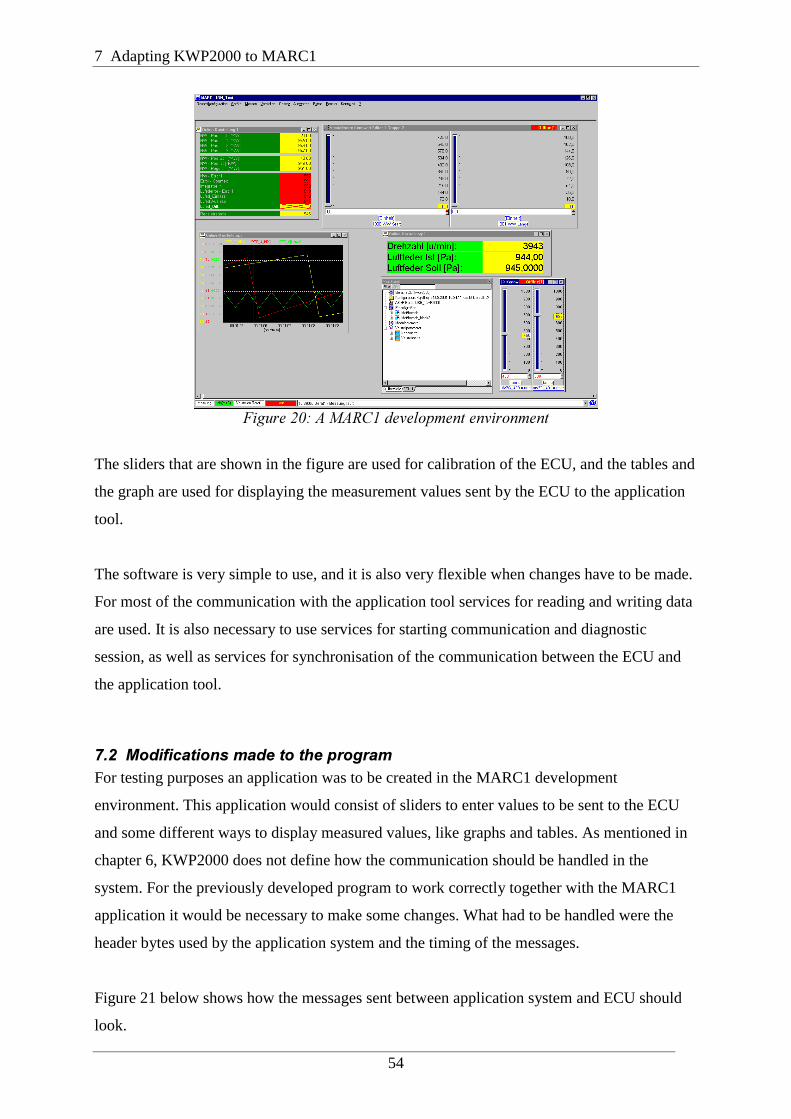
7 Adapting KWP2000 to MARC1
54
��������0������/���� ����������� ��������
The sliders that are shown in the figure are used for calibration of the ECU, and the tables and
the graph are used for displaying the measurement values sent by the ECU to the application
tool.
The software is very simple to use, and it is also very flexible when changes have to be made.
For most of the communication with the application tool services for reading and writing data
are used. It is also necessary to use services for starting communication and diagnostic
session, as well as services for synchronisation of the communication between the ECU and
the application tool.
.����$ ������������ ������������For testing purposes an application was to be created in the MARC1 development
environment. This application would consist of sliders to enter values to be sent to the ECU
and some different ways to display measured values, like graphs and tables. As mentioned in
chapter 6, KWP2000 does not define how the communication should be handled in the
system. For the previously developed program to work correctly together with the MARC1
application it would be necessary to make some changes. What had to be handled were the
header bytes used by the application system and the timing of the messages.
Figure 21 below shows how the messages sent between application system and ECU should
look.

7.2 Modifications made to the program
55
Header bytes
�������������KWP2000 message
�������Check sum
���
Formatbyte
Sourceaddress
Targetaddress
Lengthbyte
Messagetype
Data bytes Check sum
�����������������!���23$�000���������
At the beginning of the message there are a number of header bytes. The first byte, the format
byte, gives some information about the message and how it is formatted. For instance it
contains information about whether or not the following three header bytes, source address,
target address and length byte, are available. The first two bits of the format byte show what
kind of addressing is used, while the remaining six bits either contain the length of the
message, if no length byte is used, or are all zero, if a length byte is available in the message.
This is shown in figure 22 below.
Address bits
�������Length bits
�����������������
Bit 1 Bit 2 Bit 1 Bit 2 Bit 3 Bit 4 Bit 5 Bit 6�������������������!�����!����������
After the header bytes you find the real KWP2000 message. The first byte of the message
provides information about what kind of message it is. For request messages this is the service
identifier, telling the ECU what service to perform. For response messages this byte indicates
a positive or negative response. Following this byte are data bytes that are dependant on
which service has been requested. Finally there is a checksum byte at the end of the message
that can be used to determine if the message has arrived without being modified during the
transmission.
The checksum is calculated by adding all the characters in the message. At the receiving end
the checksum is once again calculated and compared to the checksum that has been received
together with the message. If it turns out that the message is in some way incorrect the
message will be ignored, and no response will be sent. This will force a retransmission of the
message, which will then hopefully arrive in a correct format.

7 Adapting KWP2000 to MARC1
56
The code needed for handling the header bytes and the checksum had already been written for
the test with the terminal program and the log files, as described in chapter 6, so no changes
had to be made in that area of the program.
Something that had not yet been handled by the program was the timing of the messages sent.
Since the application tool sends out a new request every 500 ms and does not accept a
response until 20 ms after the last message byte has been sent, some kind of timer had to be
added to the system. The timer would be used to make sure that the ECU sent a response
message to a received request sometime between 20 ms and 500 ms after the reception of the
last byte of the message, as shown in figure 23 below.
20 ms 500 msResponse not allowed Send response Timeout
���������������������!������������������
If 500 ms pass and a response has not yet been received by the application tool, a
communication timeout will occur and a new message will be sent to the ECU. Similarly, if
the ECU does not receive a request from the application tool before 5000 ms has passed there
will be a timeout on the ECU side, and the protocol must be reset. This is because the Baud
rate has to be changed if future messages shall be received correctly, and it is also necessary
to reset some flags and counters.
To implement the timer one of the RTEC’s PWM (Pulse Width Modulator) channels were
used. This allows the programmer to make the ECU generate an interrupt every time a
programmable number of system clock cycles has passed. There are two registers that have to
be written to get the right timer period generated by the PWM channel, as described in (Pulse
Width Modulator Reference Manual, 2001). You first write the prescale register with the
number of system clocks that should be used for measuring the period. Then you write the
desired period, in number of system clocks, to the period register. For everything to operate
correctly it will also be necessary to write a value, smaller than the period, to the pulse width
register. After the registers have been initialised in this manner you can write the PWM
control register and enable the generation of an interrupt every time the PWM counter reaches
the programmed period.

7.3 A MARC1 application example
57
For our system the PWM was set to generate an interrupt every millisecond. For the timing of
the communication on the serial port two counters were used. These were incremented every
time the interrupt servicing routine of the PWM was called. When the last character of a
request message was received one of the counters were reset. When it had once again reached
20 a flag was set in the interrupt servicing routine to let the system know that it was now
allowed to send a response to the request. The 5000 ms counter was reset every time a
character was received. If there was no character received for more than 5000 ms a routine
was called to reset the protocol. As mentioned this reset operation involves setting flags and
other variables to default values, as well as setting the Baud rate of the system to the default
value of 10400.
.����#�$#�)��������������7�����For evaluation purposes a simple application was put together in MARC1. This application
consisted of elements enabling measurements, calibrations and access to look-up tables
defined in the ECU. A screenshot of the application is shown in figure 20.
Each control in the application must be assigned an ID, which can then be sent to the ECU
together with the request message to tell it what structure or what memory location in the
ECU should be read or written. The assignment of ID:s is done in a configuration file, and
together with the ID there is also information about what data types should be used, possible
limits for values and dimensions if applicable. For configuration of MARC1 some of the
configurations used for the power PC system were modified so that they would work together
with the ARM based ECU.
The test application gives the user the possibility to perform measurements on some data
structures in the ECU and have the read values presented in tables and graphs. When the user
requests the start of a measurement by clicking the measurement button, this information is
what is sent between the ECU and the application system.
IIIIIIIIIIIIIIIIIIIIIIIII. ������#���� C�!��������������� C�($�$25��4���( ������5���5C>5C��0@�������� ��� C�+=9�����J������/���>�����KLLLLLLLLLLLLLLLLLLLLLLLLL
./:��������C���>���J@-�K
Fri Aug 31 13:43:14.706 2001TxD: InitPattern 81 18 F1 81 0B

7 Adapting KWP2000 to MARC1
58
Fri Aug 31 13:43:14.816 2001RxD: 80 F1 18 03 C1 DF 8F BB
Fri Aug 31 13:43:14.816 2001TxD: 83 18 F1 10 86 04 26
Fri Aug 31 13:43:14.886 2001RxD: 80 F1 18 02 50 86 61
����C��74���J@-�K
Fri Aug 31 13:43:14.906 2001TxD: 82 18 F1 83 00 0E
Fri Aug 31 13:43:14.956 2001RxD: 80 F1 18 02 7F 10 1A
Fri Aug 31 13:43:14.986 2001TxD: 83 18 F1 21 FA 01 A8
Fri Aug 31 13:43:15.046 2001RxD: 80 F1 18 3F 61 FA 01 2C 04 F5 44 00 80 00 44 00 C0 00 44 00 00 01 44 00 40 01 44 00 80 01 44 ...
Fri Aug 31 13:43:15.056 2001TxD: 83 18 F1 21 FA 02 A9
Fri Aug 31 13:43:15.116 2001RxD: 80 F1 18 3F 61 FA 02 00 00 50 42 00 C0 00 44 00 00 01 44 00 40 01 44 00 00 68 42 00 C0 01 44 ...000
The first message that is sent (TxD) to the ECU is a request to start communication. If a
positive response is received (RxD) the application requests a diagnostic session to be started.
Then the Baud rate is changed, and the application sends a message to make sure that the
ECU has changed Baud rate and the communication is still operating correctly. After these
transmissions have been made the measurements can be performed. One measurement is
made every 500 ms until the user ends the measurement session by going offline.
For the testing performed no real measurements were made. Instead the program was made to
create data that could be transmitted when a measurement was requested by the application. It
would be just as simple to fetch the measurement values from some register tied to one of the
sensors in the engine.
For writing data to the ECU the application has two slider controls. Data can be sent either by
simply clicking and moving the slider or by typing a value into the box at the bottom of the
slider control. This can be used for calibration purposes during development. Before any
values can be written the user must go online by clicking the calibration button. When this is

7.3 A MARC1 application example
59
done the application first sends a request to the ECU to read the values currently stored in the
available data structures, and displays these values on the controls in the user interface.
As previously mentioned, a look-up table was also implemented in the application and in the
ECU. Look-up table blocks are available in Simulink for design of control structures. A look-
up table is used to map a number of inputs to an output using linear interpolation. For the test
application a 2D look-up table was used. This block has two inputs and one output. Two
vectors, corresponding to x and y axes, are defined, and for each pair of values in these two
vectors a data value is assigned. If two input values to the look-up table matches row and
column parameters the output will be the data value at the intersection of the row and column,
otherwise an interpolation will be performed. The look-up table is defined in the ECU as the
following data structure:
#���� � �� CHARAC_2DIM_FIELD_FLOAT_Tag{
��� x[11];��� y[11];
��� data[121];}CHARAC_2DIM_FIELD_FLOAT;
The program initialises this structure to some suitable values at the start-up of the system, and
the data values can then be changed from the graphical user interface, either by entering the
value in a table or by clicking and dragging 2D or 3D graphs. Figure 24 shows how the look-
up table is presented in the MARC1 application system, as a 3D graph and a simple table.
�������� �+��*-����������������/�

7 Adapting KWP2000 to MARC1
60
When the values of the look-up table are changed, the application sends a request to the ECU
to update the affected data structures. This communication looks the following way when the
value 65 is written to x-position 7 and y-position 5.
IIIIIIIIIIIIIIIIIIIIIIIII. ������#���� C�!��������������� C�($�$25��4���( ������5���5C>4C��047������� ��� C�+=9�����J������/���>�����KLLLLLLLLLLLLLLLLLLLLLLLLL
./:��������C���>���J@-�K
Fri Aug 31 13:46:27.363 2001TxD: InitPattern 81 18 F1 81 0B
Fri Aug 31 13:46:27.473 2001RxD: 80 F1 18 03 C1 DF 8F BB
Fri Aug 31 13:46:27.473 2001TxD: 83 18 F1 10 86 04 26
Fri Aug 31 13:46:27.543 2001RxD: 80 F1 18 02 50 86 61
����C��74���J@-�K
Fri Aug 31 13:46:27.563 2001TxD: 82 18 F1 83 00 0E
Fri Aug 31 13:46:27.613 2001RxD: 80 F1 18 02 7F 10 1A
Fri Aug 31 13:46:27.613 2001TxD: 88 18 F1 3B FC 0F A0 00 90 41 00 48
Fri Aug 31 13:46:27.693 2001RxD: 80 F1 18 04 7B FC 0F A0 B3
The first three messages are used to establish stabile communication, as for the measurement
operation described above. Then the actual writing to the look-up table is performed (TxD: 88
18 F1 3B FC 0F A0 00 90 41 00 48). The value 90 is the offset from the start of the look-up
table structure in the ECU corresponding to the x and y coordinates, and 41 is the hex-value
for 65.
.�'��,���������������������During testing there were at first some problems with values not showing correctly during
measurements and calibrations. For the configuration of these services the same kind of
configurations as for the power PC based system had been used. It turned out that the problem
was that this system and the ARM based system uses different byte ordering. The ARM
system uses little endian byte ordering, while the power PC system uses big endian byte
ordering. Since the configurations also contain limits for what values are allowed, this meant

7.4 Testing the application
61
that some values were set to zero because they exceeded the limit, and the values that were
left unaltered still did not show up correctly. By modifying the configurations this problem
was removed.
Another thing that was discovered was that the application system uses two byte integers
while the ARM system uses four byte integers. This caused the wrong number of values to be
transmitted during measurements when the values were declared as integers. This was simply
solved by changing the data types of the variables in the ARM system from integer to short
integer.
One known problem is that the system currently can not handle large look-up tables. If the
data of the table require more than 245 bytes of memory, there would be a need for the
application to send repeated requests to read the whole look-up table from the ECU. This is
because the communication buffer can not hold more data than that. Currently this is not
working correctly. The application system will only send one read request, even if that is
insufficient to transfer the whole look-up table. This is believed to be caused by the
application system and not by the protocol implementation. The reason for the problem is
probably a faulty driver.
After the necessary changes had been made the application was running smoothly and could
be used to perform measurements and write data to the ECU. The measurements were set to
take place every 500 ms. This is the frequency that had been used for measurements on the
older development system. Some measurements were made with the help of an oscilloscope
to determine how much time the ECU needed to handle the requests currently used. One of
the RTEC’s general purpose input/output channels, as described in (General Purpose
Input/Output Reference Manual, 2001), was used to toggle a pin on the LLIB at the start and
theend of the request handling in the ECU, thereby creating a waveform on the oscilloscope
that could be used to measure the time needed for processing. This test showed that the ECU
currently needs significantly less than 20 ms to handle the requests. Since 20 ms is the time
the ECU must wait before responding to a request, this means that it is this time that limits the
possible frequency of measurements.

7 Adapting KWP2000 to MARC1
62
.�+��)���������� �������5"4�666���$#�)�By setting up some simple functions in the MARC1 application system the implementation of
the protocol has been tested and is now working correctly, except for the handling of large
look-up tables. It is believed that a faulty driver is causing problems when handling these
structures. Some modifications had to be made to the program, like adding a timer function.
The simple formatting of the messages had previously been tested with the PC terminal
program and, as thought, this part of the program did no need to be modified.
The current system is very simple and basically only consists of some drivers for the SCI and
the implementation of KWP2000. In the future, when more functions are added, it will be
important to make sure that the timing of the protocol is not disturbed. If for instance more
interrupt sources are added, these must be assigned the right priority so that they do not cause
the timers to stop working. If this would mean that the timing functionality would have to be
implemented in some other way, there would probably still be no need to do any changes to
the main part of the protocol. Also when more functions are added to the protocol
implementation the same precautions have to be taken to make sure that the communication
remains stabile.

63
2�����'�&�����������&��������������)��&�&��This chapter comments on the values and the shortcomings of the software developed.
Suggestions are also given for how development could proceed in the future and how the
software could be improved.
1����,��� ������ �������Due to some time consuming hardware problems that had to be solved, not all of the planned
work could be completed. It is still believed though, that this work has to some extent paved
the way for future development on the system.
Drivers for the serial communication interface have been developed and tested, and
communication with external devices now operates correctly. The SCI routines will probably
be useful in the future, and new ones can easily be developed now that the hardware has been
fully tested and is considered to be fully functioning.
The APIC was used for the implementation of interrupt driven serial communication and an
interrupt driven timer. The developed APIC routines show how to set up the system in order
for the interrupt handling to work. They also show how the future interrupt servicing routines
for the other interrupt sources should be written. This will probably be helpful for other
developers.
The implemented communication protocol was tested using the MARC1 application system,
and is believed to be functioning correctly. The testing performed with the Visual Basic
terminal program, though somewhat theoretical, should also show that the services not
requested by the measurement application have been implemented correctly.
1����&������������������ ���������The developed communication protocol has been tested using the MARC1 application
system, creating a simple measurement and calibration application. Hopefully this test is
enough to show that the implementation is fully functioning, and if problems would still arise

8 Conclusions and suggestions for the future
64
in the future it is thought that only minor changes would have to be done to get a fully
functioning system. During the testing one problem was discovered when reading large data
structures in the ECU. This is believed to be caused by the application system and not by the
software running on the ECU system. To gain certain knowledge in this area it will be
necessary to do some more testing of this functionality in the future.
The ECU currently only supports a small subset of the requests covered by KWP2000. In the
future it might be necessary to add support for additional services, which could easily be done
by adding appropriate code fragments to the service handling part of the protocol
implementation.
To reduce the number of interrupts that are being generated the timer could be changed. It
currently generates an interrupt every ms, but it would be possible to change this to have it
generate an interrupt every 20 ms, thus reducing the number of timer interrupts by a factor
twenty. The reception of messages could also be changed to reduce the number of interrupts
for this purpose. Currently an interrupt is generated every time a character is received. This
could be changed by letting the program check the first byte of the received message to see
how many bytes must be received, and then setting the RBNFC bits in the buffered SCI
control register to have an interrupt generated when the whole message has been received.
Something that must be considered in that case is the fact that some messages will contain
more than sixteen bytes, and will therefor not fit in the receive buffer. In those situations an
interrupt would have to be generated each time the buffer was full. When changing Baud rate
the program currently must wait for a while to make sure that the transmit buffer is empty
before the Baud rate is changed. This means that the program will be halted for a while,
which of course is not so good. It is therefor desired to make changes to eliminate this
problem.
A new version of the program that solves the problems with the timer interrupts and the Baud
rate change was actually written. This program generates a timer interrupt every 20 ms and
uses a counter to decide when enough time (presently between 40 and 60 ms) has passed for
the Baud rate change to be made. Since the license for the application system had expired this
program could only be tested with the PC terminal program, and it is therefor not certain that
it would work with the application system. This is something that must be determined in the
future, and possibly some modifications to this program must be made.

8.3 Evaluation of the development system
65
The developed routines for the APIC can be used in the future when more of the ECU
functions are implemented, and more interrupt sources are added to the system. This could be
done by simply using the developed routines for enabling and configuring the needed
interrupt sources, or the developed code could be used as a template to develop new routines
more suitable for a certain usage. This part of the system is thought to have been fully tested
at the completion of this work.
The developed and tested serial port connection to the PC could probably be used in the future
for sending commands to the system when testing and evaluating new functions that have
been developed. If more routines would be needed these could easily be implemented,
possibly by using the routines already developed or by using them as guidance.
1����*��������������� ����������� ����During the work some problems were encountered with the hardware. It was not always as
simple as it should be to do development. The reason for this is that the system is very new
and has not yet been fully tested, and therefor some problems are likely to be encountered.
During the future development on the system, when other functionality of the ECU is used,
other problems might very well occur and have to be dealt with.
It is believed though, that when the system has matured and when it has been fully tested it
will probably allow developers to do fast ECU development. The RTEC will allow for very
fast development of new drivers and the ARM based system will allow for very flexible
adjustment of the hardware. By using Matlab, Simulink and Real-Time Workshop for the
development of control algorithms this can also be done in a very fast and efficient way. The
MARC1 application system and Real-Time Workshop will also allow people to work with
ECU and engine development without knowing how to perform software development for the
system. Putting these parts together and getting them to work properly will provide a great
system for the development and testing of new engine control functions.
1�'��)��������Even though not as much of the work as desired could be completed, the work on this thesis
has still provided some valuable insight into close to hardware programming and development
of engine control systems. It has also been an opportunity to practice a kind of practical

8 Conclusions and suggestions for the future
66
problem solving that is not often encountered at the university. Hopefully the completed work
will be useful for the people who will be working with the same system and the same tools in
the future.

67
������'��
�$"/���!��������������07�,AIEC, 2001
������ �������1�����8��������7���� �������%����,ARM, 2000
Bilting U. & Skansholm J.,89���������/, 3rd ed.,Studentlitteratur, ISBN 91-44-01468-6, 2000
Burns A. & Wellings A.,����-��������������������������������������, 2nd ed.,Addison-Wesley, ISBN 0-201-40365-X, 1997
�/�5/���!��������������07�,AIEC, 2001
5:/;�5���!��������������07�,AIEC, 2001
%�������$�������"����<;��������!�������������,AIEC, 2001
Gupta R. K.,/�-1����������!�=���'��������1�!�'����!�����������5��������1������,Kluwer Academic Publishers, ISBN 0792396138, 1995
2��'����$���������000���4������������!�������,DaimlerChrysler, 2001
Kiencke U. & Nielsen L.,�������� ������������������!���������>���� �����>����� ������,Springer-Verlag, ISBN 3-540-66922-1, 2000
$�����3�����������������!�������������,AIEC, 2001
?1/"���!�������������,AIEC, 2001
Roos O.,%�����9��������������*��*,Studentlitteratur, ISBN 91-44-46651-X, 1995
Schilling D. L. & Belove C.,5������������������>������������������������, 3rd ed.,McGraw-Hill, ISBN 0-07-055348-3, 1989

References
68

69
����� $3��4�#��'���
Private Sub Change_Baud_Rate_Click()
M�������1���� ��� Option1.Value = True $*��MSComm1.Settings = "9600,N,8,1"Option2.Value = TrueLabel3.Caption = "Baud rate = 10400"Text14.Text = "Set B-rate = 10400"����� Option2.Value = True $*��MSComm1.Settings = "57600,N,8,1"Option1.Value = TrueLabel3.Caption = "Baud rate = 57600"Text14.Text = "Set B-rate = 57600"�����
End Sub
Private Sub Open_Comm_Click()
� MSComm1.PortOpen = False $*��M������������ ��MSComm1.CommPort = 1MSComm1.Settings = "9600,N,8,1"MSComm1.PortOpen = True
M�*������������������Label11.Caption = "Communication open"Text14.Text = "Comm opened"����Text14.Text = "Comm already open"�����
End Sub
Private Sub Close_Comm_Click()
� MSComm1.PortOpen = True $*��M�������� ��MSComm1.PortOpen = False
M�*������������������Label11.Caption = "Communication closed"Text14.Text = "Comm closed"����Text14.Text = "Comm already closed"�����

APPENDIX A: VB code
70
End Sub
Private Sub MSComm1_OnComm()
� MSComm1.CommEvent = comEvReceive $*��Text14.Text = "Character received"MSComm1.RThreshold = 0�����
End Sub
Private Sub Clear_Display_Click()
M.��� ����*��������#� Check2.Value = 1 $*��Text7.Text = ""Text8.Text = ""Text9.Text = ""Text10.Text = ""Text11.Text = ""Text12.Text = ""Text13.Text = ""Text2.Text = ""Text3.Text = ""Option3.Value = TrueText14.Text = "Receive fields cleared"�����
M.��� ����*�� ���������� � Check1.Value = 1 $*��MSComm1.InBufferCount = 0Text1.Text = 0�����
End Sub
Private Sub Read_Bytes_Click()
number_of_bytes = MSComm1.InBufferCount
� Option3.Value = True And number_of_bytes > 0 $*��Text7.Text = Hex(Asc(MSComm1.Input))Option4.Value = Truenumber_of_bytes = number_of_bytes - 1Text1.Text = number_of_bytes����� Option4.Value = True And number_of_bytes > 0 $*��Text8.Text = Hex(Asc(MSComm1.Input))Option5.Value = Truenumber_of_bytes = number_of_bytes - 1Text1.Text = number_of_bytes����� Option5.Value = True And number_of_bytes > 0 $*��

APPENDIX A: VB code
71
Text9.Text = Hex(Asc(MSComm1.Input))Option6.Value = Truenumber_of_bytes = number_of_bytes - 1Text1.Text = number_of_bytes����� Option6.Value = True And number_of_bytes > 0 $*��Text10.Text = Hex(Asc(MSComm1.Input))Option7.Value = Truenumber_of_bytes = number_of_bytes - 1Text1.Text = number_of_bytes����� Option7.Value = True And number_of_bytes > 0 $*��Text11.Text = Hex(Asc(MSComm1.Input))Option8.Value = Truenumber_of_bytes = number_of_bytes - 1Text1.Text = number_of_bytes����� Option8.Value = True And number_of_bytes > 0 $*��Text12.Text = Hex(Asc(MSComm1.Input))Option9.Value = Truenumber_of_bytes = number_of_bytes - 1Text1.Text = number_of_bytes����� Option9.Value = True And number_of_bytes > 0 $*��Text13.Text = Hex(Asc(MSComm1.Input))Option10.Value = Truenumber_of_bytes = number_of_bytes - 1Text1.Text = number_of_bytes����� Option10.Value = True And number_of_bytes > 0 $*��Text2.Text = Hex(Asc(MSComm1.Input))Option11.Value = Truenumber_of_bytes = number_of_bytes - 1Text1.Text = number_of_bytes����� Option11.Value = True And number_of_bytes > 0 $*��Text3.Text = Hex(Asc(MSComm1.Input))Option3.Value = Truenumber_of_bytes = number_of_bytes - 1Text1.Text = number_of_bytes�����
End Sub
Private Sub Start_Communication_Click()
M�� �+=9������������������ MSComm1.PortOpen = True $*��MSComm1.Output = Chr(&H81)MSComm1.Output = Chr(&H18)MSComm1.Output = Chr(&HF1)MSComm1.Output = Chr(&H81)MSComm1.Output = Chr(&HB)MSComm1.RThreshold = 1Text14.Text = "Message sent"����Text14.Text = "Open comm first"

APPENDIX A: VB code
72
�����
End Sub
Private Sub Start_Routine_By_Identifier_Click()
M�� � �������#�������������� � MSComm1.PortOpen = True $*��MSComm1.Output = Chr(&H82)MSComm1.Output = Chr(&H18)MSComm1.Output = Chr(&HF1)MSComm1.Output = Chr(&H31)MSComm1.Output = Chr(&H1)MSComm1.Output = Chr(&HBD)MSComm1.RThreshold = 1Text14.Text = "Message sent"����Text14.Text = "Open comm first"�����
End Sub
Private Sub Read_Memory_Click()
M"�������� #��#���� ���� MSComm1.PortOpen = True $*��MSComm1.Output = Chr(&H85)MSComm1.Output = Chr(&H18)MSComm1.Output = Chr(&HF1)MSComm1.Output = Chr(&H23)MSComm1.Output = Chr(&H0)MSComm1.Output = Chr(&H0)MSComm1.Output = Chr(&H0)MSComm1.Output = Chr(&H1)MSComm1.Output = Chr(&HB2)MSComm1.RThreshold = 1Text14.Text = "Message sent"����Text14.Text = "Open comm first"�����
End Sub
Private Sub Request_Download_Click()
M"�F������������� MSComm1.PortOpen = True $*��MSComm1.Output = Chr(&H88)MSComm1.Output = Chr(&H18)MSComm1.Output = Chr(&HF1)MSComm1.Output = Chr(&H34)

APPENDIX A: VB code
73
MSComm1.Output = Chr(&H0)MSComm1.Output = Chr(&H0)MSComm1.Output = Chr(&H0)MSComm1.Output = Chr(&H1)MSComm1.Output = Chr(&H0)MSComm1.Output = Chr(&H0)MSComm1.Output = Chr(&H1)MSComm1.Output = Chr(&HC7)MSComm1.RThreshold = 1Text14.Text = "Message sent"����Text14.Text = "Open comm first"�����
End Sub
Private Sub Request_Upload_Click()
M"�F����������� MSComm1.PortOpen = True $*��MSComm1.Output = Chr(&H88)MSComm1.Output = Chr(&H18)MSComm1.Output = Chr(&HF1)MSComm1.Output = Chr(&H35)MSComm1.Output = Chr(&H0)MSComm1.Output = Chr(&H0)MSComm1.Output = Chr(&H0)MSComm1.Output = Chr(&H1)MSComm1.Output = Chr(&H0)MSComm1.Output = Chr(&H0)MSComm1.Output = Chr(&H1)MSComm1.Output = Chr(&HC8)MSComm1.RThreshold = 1Text14.Text = "Message sent"����Text14.Text = "Open comm first"�����
End Sub
Private Sub Write_Data_By_Identifier_Click()
M= ��������#�������������� � MSComm1.PortOpen = True $*��MSComm1.Output = Chr(&H88)MSComm1.Output = Chr(&H18)MSComm1.Output = Chr(&HF1)MSComm1.Output = Chr(&H3B)MSComm1.Output = Chr(&HFC)MSComm1.Output = Chr(&H1)MSComm1.Output = Chr(&H90)

APPENDIX A: VB code
74
MSComm1.Output = Chr(&H42)MSComm1.Output = Chr(&HC8)MSComm1.Output = Chr(&H0)MSComm1.Output = Chr(&H0)MSComm1.Output = Chr(&H63)MSComm1.RThreshold = 1Text14.Text = "Message sent"����Text14.Text = "Open comm first"�����
End Sub
Private Sub Start_Diagnostic_Session_Click()
M�� ������������������� MSComm1.PortOpen = True $*��MSComm1.Output = Chr(&H83)MSComm1.Output = Chr(&H18)MSComm1.Output = Chr(&HF1)MSComm1.Output = Chr(&H10)MSComm1.Output = Chr(&H86)MSComm1.Output = Chr(&H4)MSComm1.Output = Chr(&H26)MSComm1.RThreshold = 1Text14.Text = "Message sent"����Text14.Text = "Open comm first"�����
End Sub
Private Sub Read_Data_By_Identifier_Click()
M"���������#�������������� � MSComm1.PortOpen = True ThenMSComm1.Output = Chr(&H84)MSComm1.Output = Chr(&H18)MSComm1.Output = Chr(&HF1)MSComm1.Output = Chr(&H21)MSComm1.Output = Chr(&HFC)MSComm1.Output = Chr(&H1)MSComm1.Output = Chr(&H90)MSComm1.Output = Chr(&H3B)MSComm1.RThreshold = 1Text14.Text = "Message sent"����Text14.Text = "Open comm first"�����
End Sub

APPENDIX A: VB code
75
Private Sub Reset_ECU_Click()
M�.%� ���� MSComm1.PortOpen = True ThenMSComm1.Output = Chr(&H82)MSComm1.Output = Chr(&H18)MSComm1.Output = Chr(&HF1)MSComm1.Output = Chr(&H11)MSComm1.Output = Chr(&H1)MSComm1.Output = Chr(&H9D)MSComm1.RThreshold = 1Text14.Text = "Message sent"����Text14.Text = "Open comm first"�����
End Sub
Private Sub Read_Troube_Codes_Click()
M"��������������������� ������������ MSComm1.PortOpen = True $*��MSComm1.Output = Chr(&H83)MSComm1.Output = Chr(&H18)MSComm1.Output = Chr(&HF1)MSComm1.Output = Chr(&H17)MSComm1.Output = Chr(&H0)MSComm1.Output = Chr(&H1)MSComm1.Output = Chr(&HA4)MSComm1.RThreshold = 1Text14.Text = "Message sent"����Text14.Text = "Open comm first"�����
End Sub

APPENDIX A: VB code
76

77
����� $3��4���(+(�'�������������5�)���


![Э = B Q ? K D B C F ? G ? > @ F ? G Llib.7480040.ru/images/books/978-5-905-248-27-6.pdf · 5 ВВЕДЕНИЕ W d h e h ] b q _ k d b c f _ g _ ^ ` f _ g l (Environmental management)](https://img.pdfslide.tips/doc/110x75/5e21a6fb8c82694fc725d15a/-b-q-k-d-b-c-f-g-f-g-llib-5-w-d-h-e-h-b-q.jpg)