Embed Size (px)
Citation preview
8/12/2019 Lecture3 Mech SU
http://slidepdf.com/reader/full/lecture3-mech-su 1/15
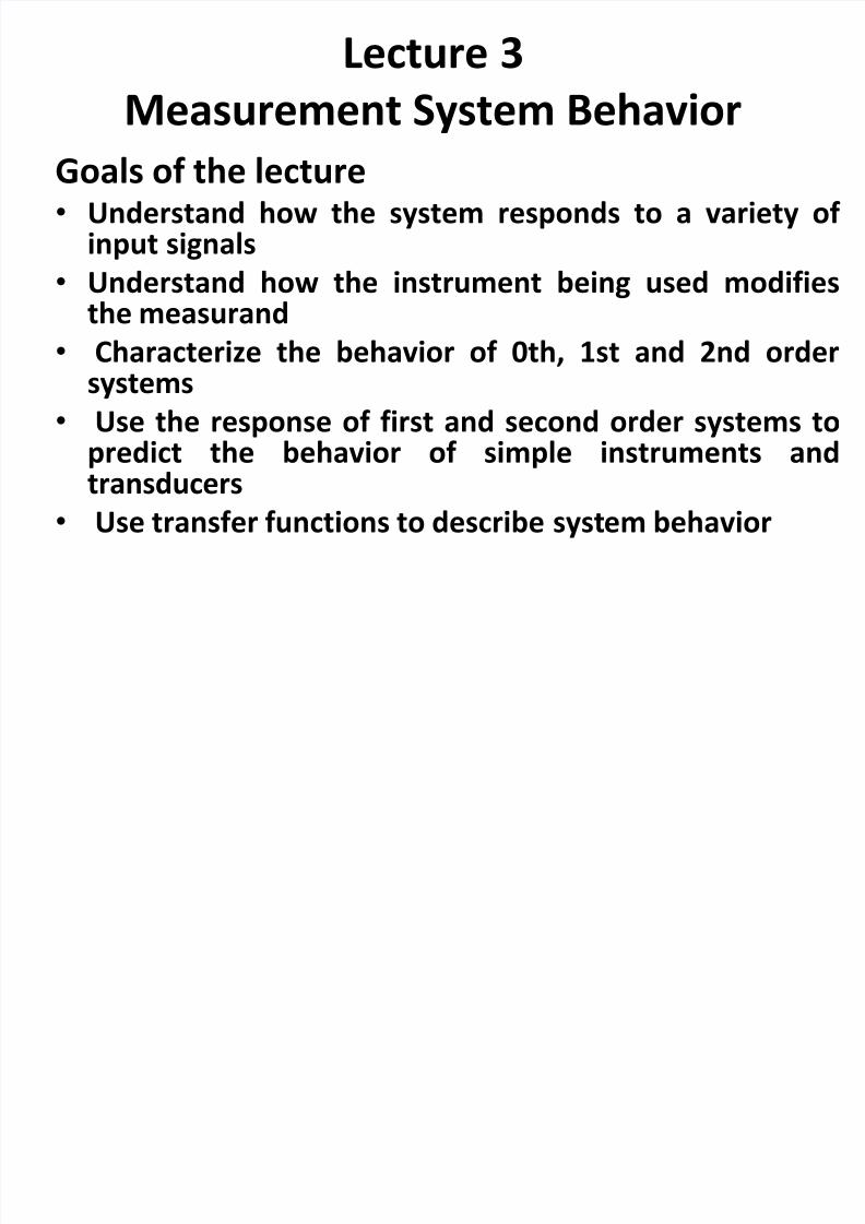
Lecture 3
Measurement System Behavior
Goals of the lecture• Understand how the system responds to a variety of
input signals
• Understand how the instrument being used modifiesthe measurand
• Characterize the behavior of 0th, 1st and 2nd ordersystems
• Use the response of first and second order systems to
predict the behavior of simple instruments andtransducers
• Use transfer functions to describe system behavior
8/12/2019 Lecture3 Mech SU
http://slidepdf.com/reader/full/lecture3-mech-su 2/15
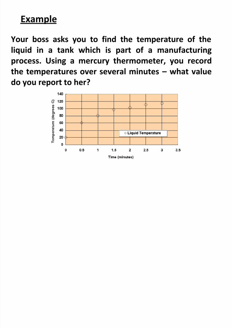
Example
Your boss asks you to find the temperature of theliquid in a tank which is part of a manufacturing
process. Using a mercury thermometer, you record
the temperatures over several minutes – what value
do you report to her?
8/12/2019 Lecture3 Mech SU
http://slidepdf.com/reader/full/lecture3-mech-su 3/15
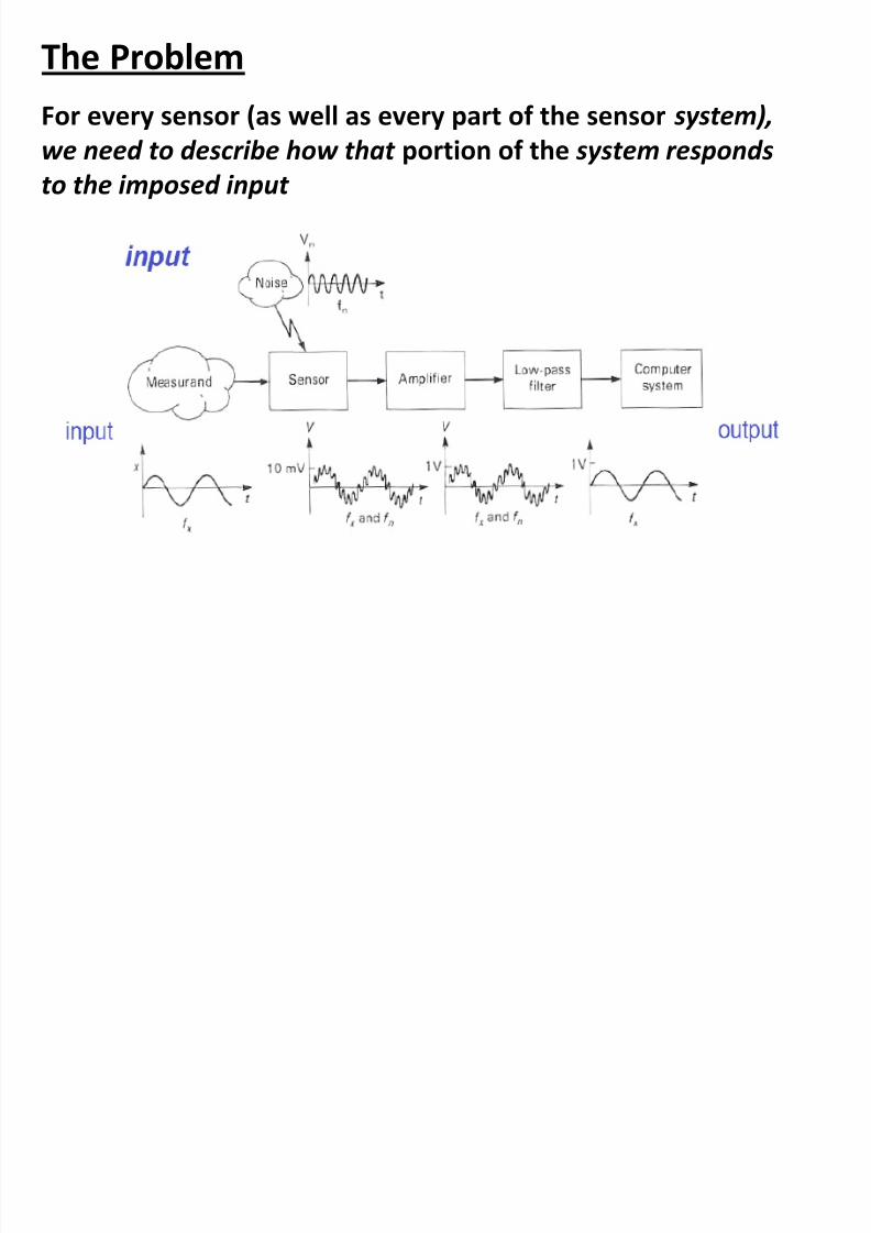
The Problem
For every sensor (as well as every part of the sensor system),
we need to describe how that portion of the system respondsto the imposed input
8/12/2019 Lecture3 Mech SU
http://slidepdf.com/reader/full/lecture3-mech-su 4/15
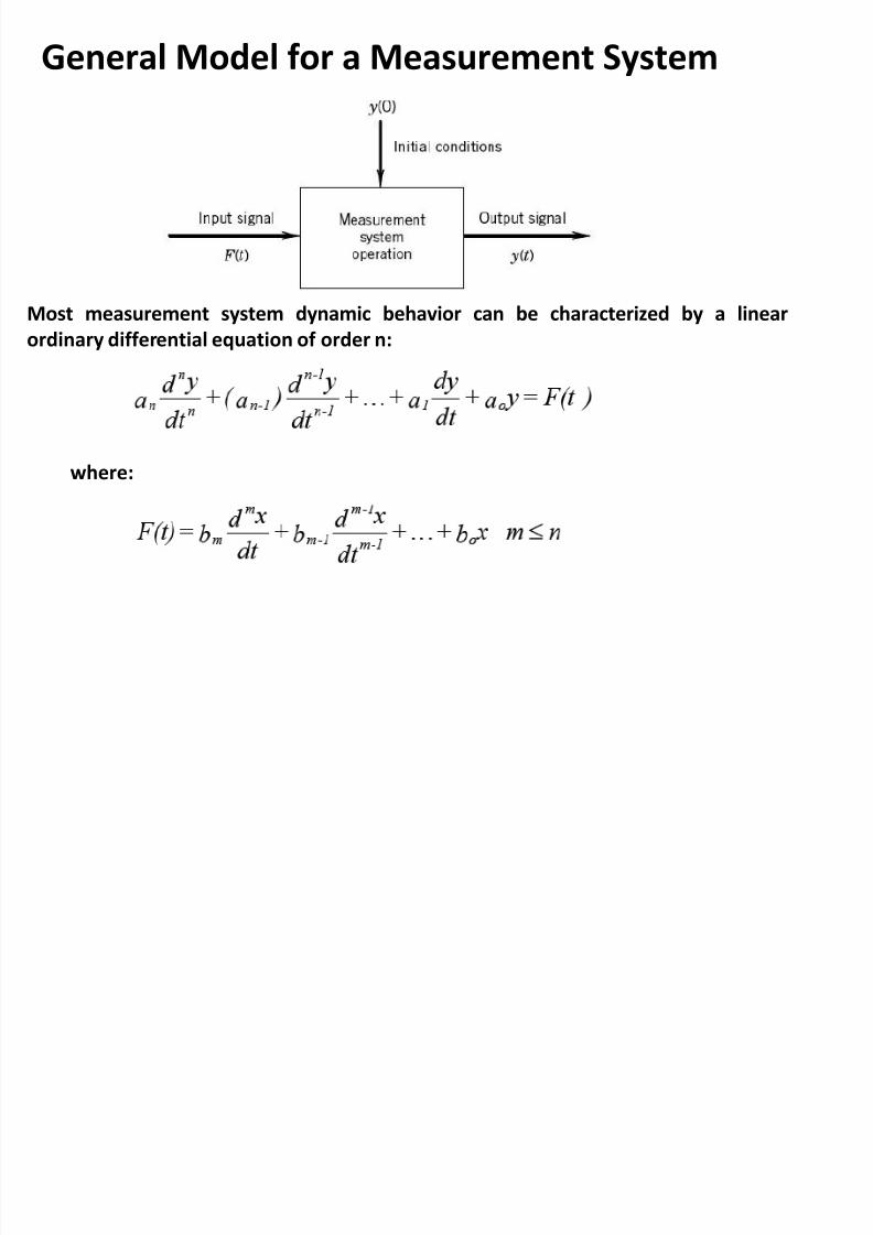
General Model for a Measurement System
Most measurement system dynamic behavior can be characterized by a linear
ordinary differential equation of order n:
where:
8/12/2019 Lecture3 Mech SU
http://slidepdf.com/reader/full/lecture3-mech-su 5/15
• System response is determined by mechanical elements (mass, stiffness, and damping)
and electrical elements (resistance, inductance, and capacitance) that form the components
of most measurement system.
– Sensors may use mechanical elements (e.g., a spring of known stiffness can be used to
determine static force by measuring spring deflection) or electrical elements (change of
resistance to measure strain as in a strain gage), or most commonly, a combination of both.
– Electrical filters, amplifiers, and other electronics use electrical elements to eliminate
noise, remove “DC” signals, or to boost signal level.
• No element is “pure” - our spring also has mass that will restrict its ability to determine
dynamic forces (i.e., the spring’s motion creates an additional force due to its
acceleration).
• Elements interact - for example, the spring’s stiffness and mass create its natural
frequency
•All systems possess damping (from friction, viscosity, inductance, etc.) that is usually
helpful
8/12/2019 Lecture3 Mech SU
http://slidepdf.com/reader/full/lecture3-mech-su 6/15
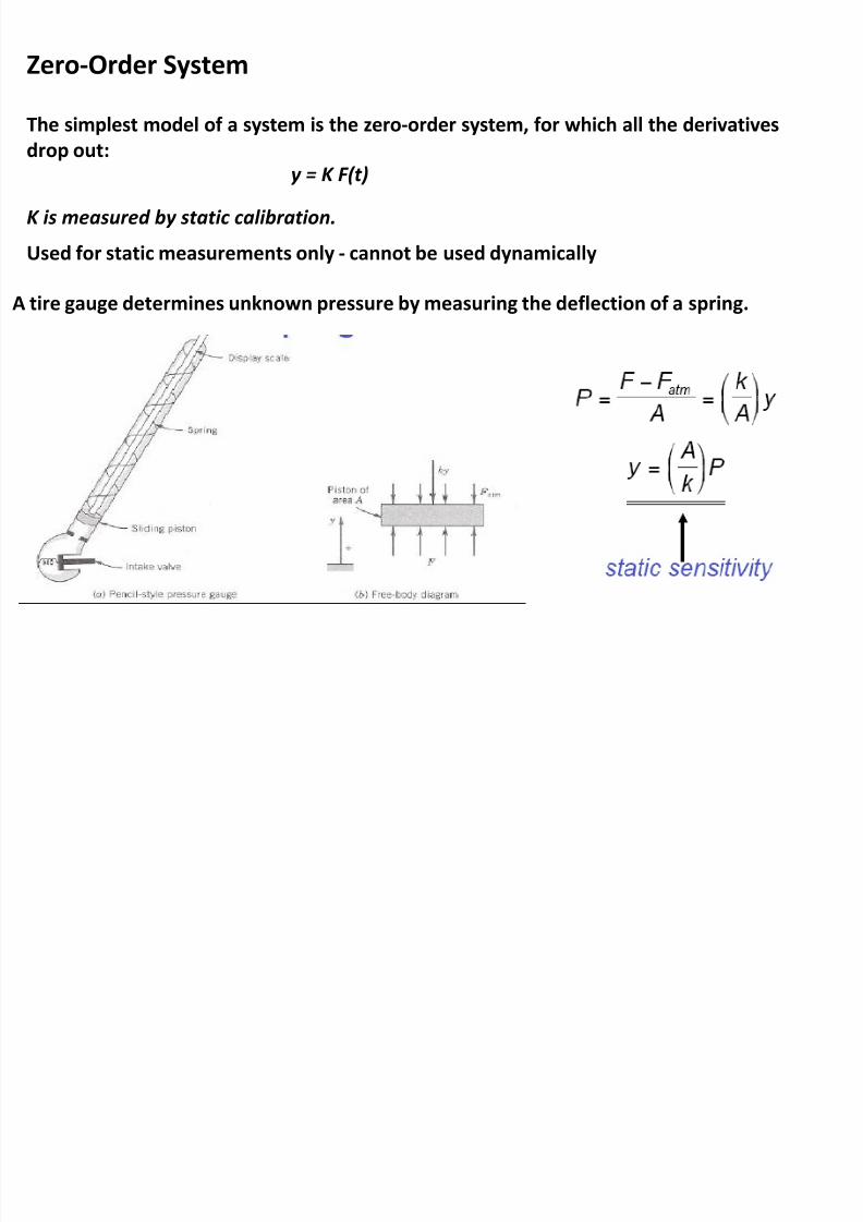
Zero-Order System
The simplest model of a system is the zero-order system, for which all the derivatives
drop out:y = K F(t)
K is measured by static calibration.
Used for static measurements only - cannot be used dynamically
A tire gauge determines unknown pressure by measuring the deflection of a spring.

8/12/2019 Lecture3 Mech SU
http://slidepdf.com/reader/full/lecture3-mech-su 7/15
First-Order Systems
Example
Suppose a bulb thermometer originally indicating 20ºC is suddenly exposed to a fluidtemperature of 37 ºC. Develop a simple model to simulate the thermometer output
response.The rate at which energy is exchanged between the sensor and the
environment through convection, , must be balanced by the
storage of energy within the thermometer, dE/dt.
For a constant mass temperature sensor,
This can be written in the form
dividing by hAs
This equation can be written in the
form first order differential equation:or
8/12/2019 Lecture3 Mech SU
http://slidepdf.com/reader/full/lecture3-mech-su 8/15
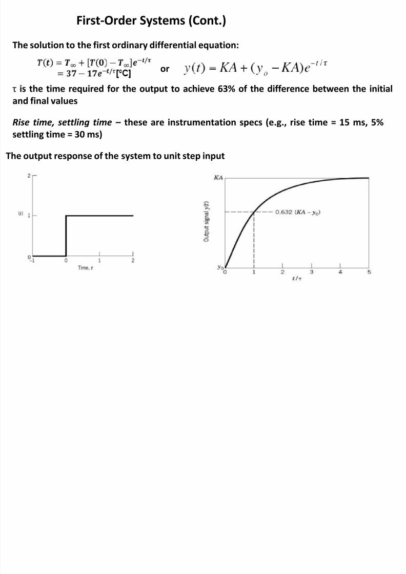
First-Order Systems (Cont.)
The solution to the first ordinary differential equation:
The output response of the system to unit step input
τ is the time required for the output to achieve 63% of the difference between the initial
and final values
or
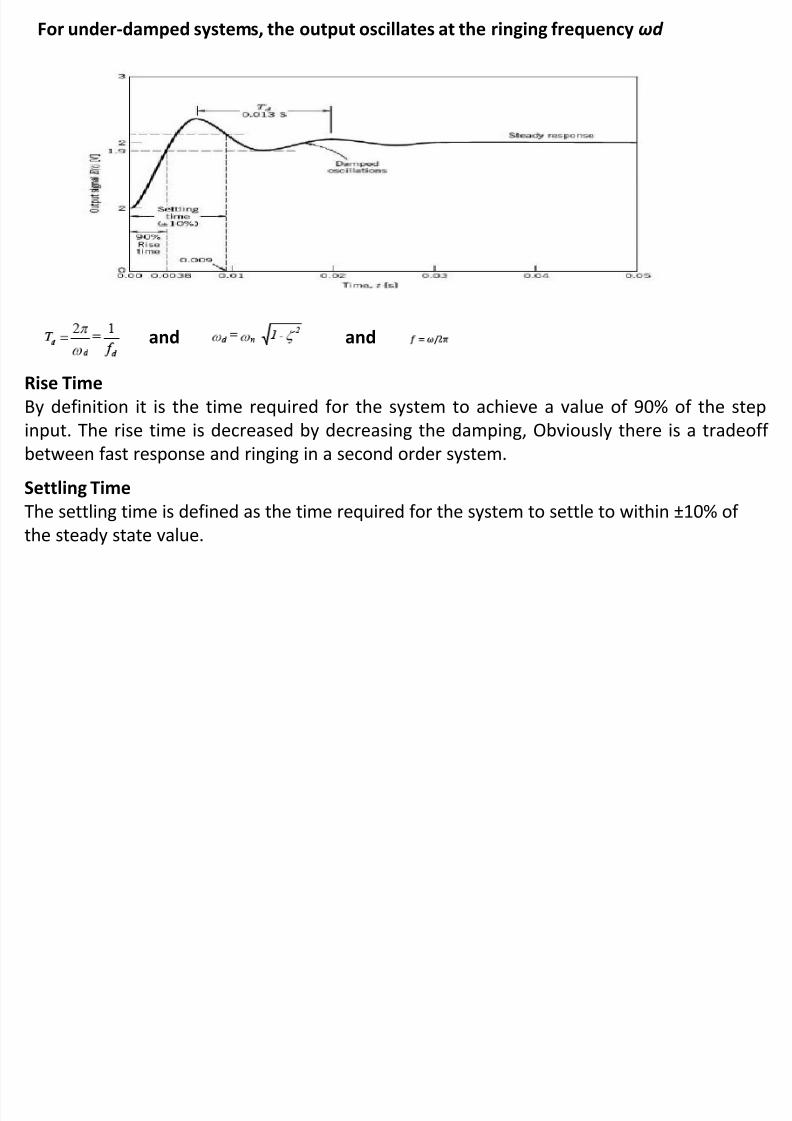
Rise time, settling time – these are instrumentation specs (e.g., rise time = 15 ms, 5%
settling time = 30 ms)
8/12/2019 Lecture3 Mech SU
http://slidepdf.com/reader/full/lecture3-mech-su 9/15
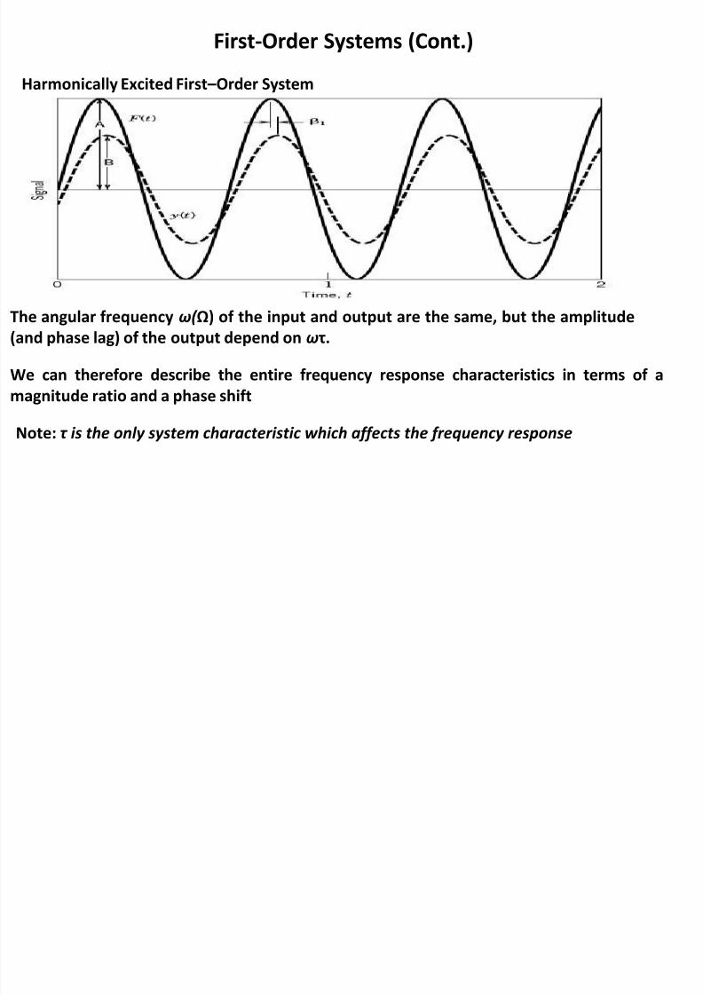
Harmonically Excited First –Order System
First-Order Systems (Cont.)
The angular frequency ω( Ω) of the input and output are the same, but the amplitude
(and phase lag) of the output depend on ωτ.
We can therefore describe the entire frequency response characteristics in terms of a
magnitude ratio and a phase shift
Note: τ is the only system characteristic which affects the frequency response
8/12/2019 Lecture3 Mech SU
http://slidepdf.com/reader/full/lecture3-mech-su 10/15
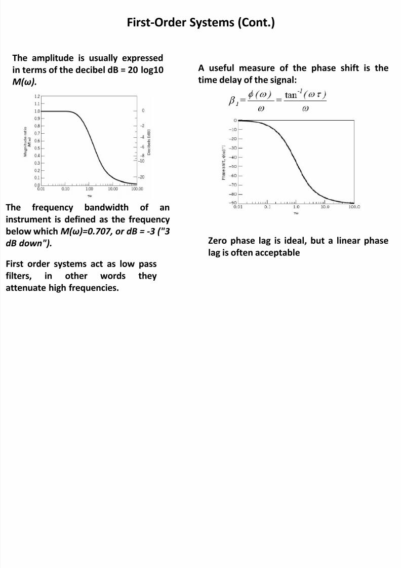
The amplitude is usually expressed
in terms of the decibel dB = 20 log10M(ω).
First-Order Systems (Cont.)
The frequency bandwidth of aninstrument is defined as the frequency
below which M(ω)=0.707, or dB = -3 ("3
dB down").
First order systems act as low pass
filters, in other words theyattenuate high frequencies.
A useful measure of the phase shift is thetime delay of the signal:
Zero phase lag is ideal, but a linear phase
lag is often acceptable
8/12/2019 Lecture3 Mech SU
http://slidepdf.com/reader/full/lecture3-mech-su 11/15
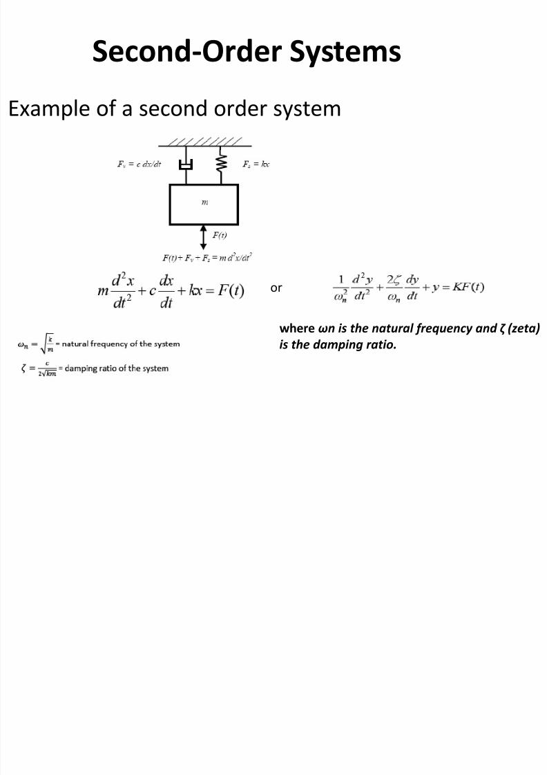
Second-Order Systems
Example of a second order system
where ωn is the natural frequency and ζ (zeta)
is the damping ratio.
or
8/12/2019 Lecture3 Mech SU
http://slidepdf.com/reader/full/lecture3-mech-su 12/15
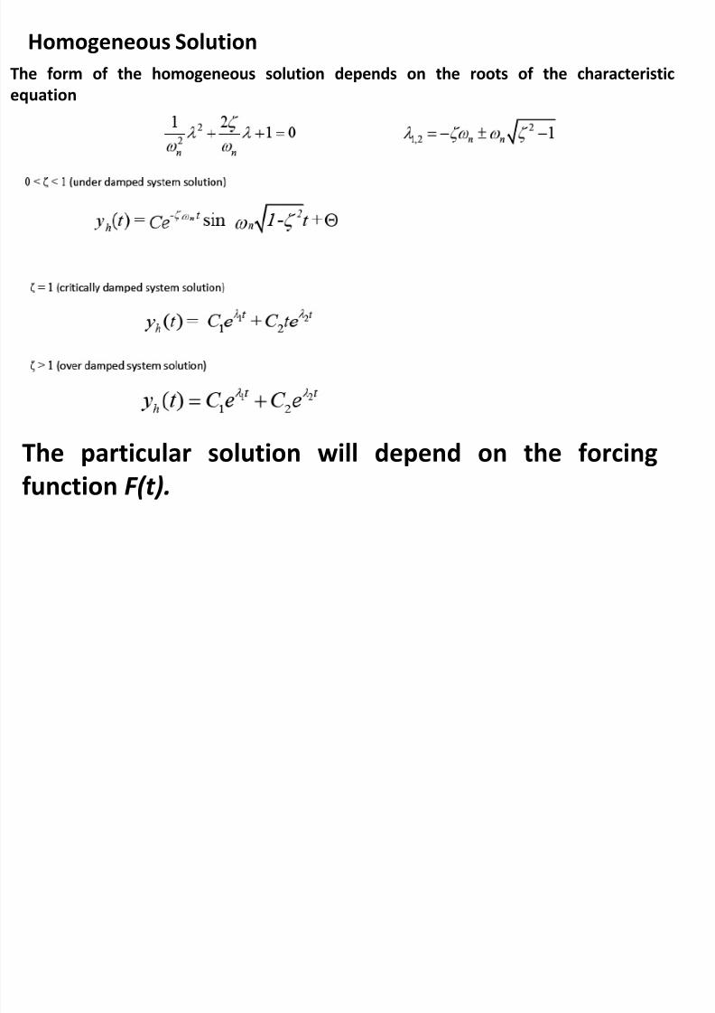
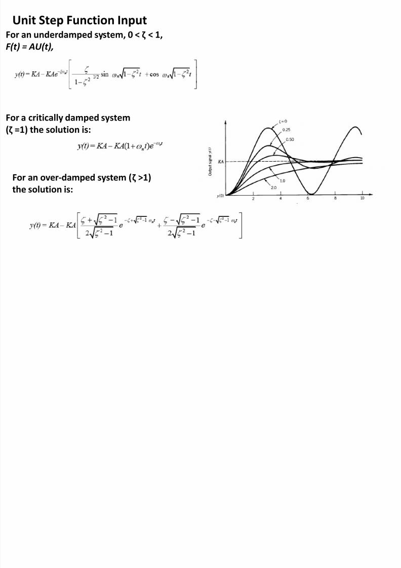
Homogeneous Solution
The form of the homogeneous solution depends on the roots of the characteristic
equation
The particular solution will depend on the forcing
function F(t).
8/12/2019 Lecture3 Mech SU
http://slidepdf.com/reader/full/lecture3-mech-su 13/15
8/12/2019 Lecture3 Mech SU
http://slidepdf.com/reader/full/lecture3-mech-su 14/15
8/12/2019 Lecture3 Mech SU
http://slidepdf.com/reader/full/lecture3-mech-su 15/15
Frequency Response
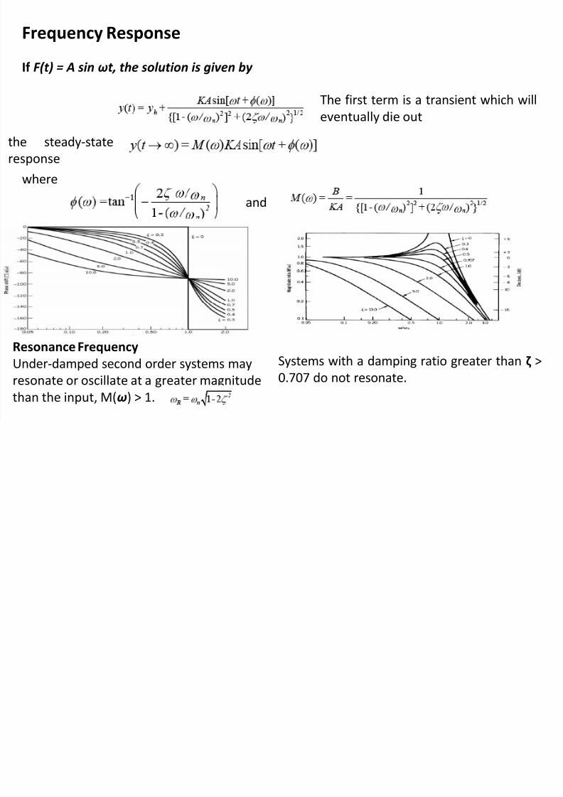
If F(t) = A sin ωt , the solution is given by
The first term is a transient which willeventually die out
the steady-state
response
where
and
Resonance Frequency
Under-damped second order systems may
resonate or oscillate at a greater magnitude
than the input, M(ω) > 1.
Systems with a damping ratio greater than ζ >
0.707 do not resonate.