Embed Size (px)
Citation preview

TREEBY LOCAL STRUCUTRE PLANLOT 703 GHOSTGUM AVENUE, TREEBY
appendix g
acoustic report(Lloyd George Acoustics)
Lloyd George Acoustics PO Box 717
Hillarys WA 6923
T: 9401 7770
www.lgacoustics.com.au
Transportation Noise Assessment
Treeby Estate, Lot 703 Armadale Road, Banjup Reference: 19054974-01
Prepared for: LWP Property

Report: 19054974‐01
Lloyd George Acoustics Pty Ltd ABN: 79 125 812 544
PO Box 717 Hillarys WA 6923
www.lgacoustics.com.au
T: 9401 7770
Contacts Daniel Lloyd Terry George Matt Moyle Olivier Mallié Ben Hillion
E:
M:
0439 032 844
0400 414 197
0412 611 330
0439 987 455
0457 095 555
Date: Rev Description Prepared By Verified
11‐Oct‐19 0 Issued to Client Matt Moyle Terry George
This report has been prepared in accordance with the scope of services described in the contract or
agreement between Lloyd George Acoustics Pty Ltd and the Client. The report relies upon data, surveys,
measurements and results taken at or under the particular times and conditions specified herein. Any
findings, conclusions or recommendations only apply to the aforementioned circumstances and no greater
reliance should be assumed or drawn by the Client. Furthermore, the report has been prepared solely for
use by the Client, and Lloyd George Acoustics Pty Ltd accepts no responsibility for its use by other parties.

Lloyd George Acoustics
Table of Contents 1 INTRODUCTION _______________________________________________________________ 1
2 CRITERIA ____________________________________________________________________ 2
2.1 Road Traffic Noise ______________________________________________________________ 2
2.2 Aircraft Noise __________________________________________________________________ 3
3 METHODOLOGY _______________________________________________________________ 4
3.1 Ground Topography _____________________________________________________________ 5
3.2 Traffic Data ___________________________________________________________________ 5
3.3 Ground Attenuation _____________________________________________________________ 6
4 RESULTS _____________________________________________________________________ 6
5 ASSESSMENT ________________________________________________________________ 11
5.1 Road Traffic Noise _____________________________________________________________ 11
5.2 Jandakot Aircraft Noise __________________________________________________________ 16
List of Tables Table 2‐1 Noise Targets for Noise‐Sensitive Land‐Use _______________________________________ 2
Table 3‐1 Noise Relationship Between Different Road Surfaces________________________________ 5
Table 3‐2 Traffic Information Used in the Modelling ________________________________________ 6
Lloyd George Acoustics
List of Figures Figure 1‐1 Proposed Subdivision Layout __________________________________________________ 1
Figure 2‐1 Site Locality in Relation to Frame Area ___________________________________________ 3
Figure 2‐2 Site Locality in Relation to ANEF Contours ________________________________________ 4
Figure 4‐1 Future Noise Monitoring Results – “Exposure A” Wall Ground Floor ___________________ 7
Figure 4‐2 Future Noise Monitoring Results – “Exposure A” Wall First Floor ______________________ 8
Figure 4‐3 Future Noise Monitoring Results – “Exposure B” Wall Ground Floor ___________________ 9
Figure 4‐4 Future Noise Monitoring Results – “Exposure B” Wall First Floor _____________________ 10
Figure 5‐1 Proposed Noise Mitigation Option 1: Ground Floor _______________________________ 12
Figure 5‐2 Proposed Noise Mitigation Option 1: First Floor __________________________________ 13
Figure 5‐3 Proposed Noise Mitigation Option 2: Ground Floor _______________________________ 14
Figure 5‐4 Proposed Noise Mitigation Option 2: First Floor __________________________________ 15
Appendices A Acceptable Treatment Packages
B Terminology

Lloyd George Acoustics
Reference: 19054974‐01 Page 1
1 INTRODUCTION Treeby Structure Plan at Lot 703 Armadale Road, Banjup is a proposed structure plan being managed
by LWP Property Group. The proposed plan is shown on Figure 1‐1 (Roberts Day Drawing No. RD1
017).
The site is bound by adjoining subdivision to the west and Armadale Road to the south. As such,
potential noise impacts from transportation (road traffic) must be considered. The site is within the
Frame Area of Jandakot airport and therefore aircraft noise must also be considered.
Figure 1-1 Proposed Subdivision Layout
Appendix B contains a description of some of the terminology used throughout this report.
Lloyd George Acoustics
Reference: 19054974‐01 Page 2
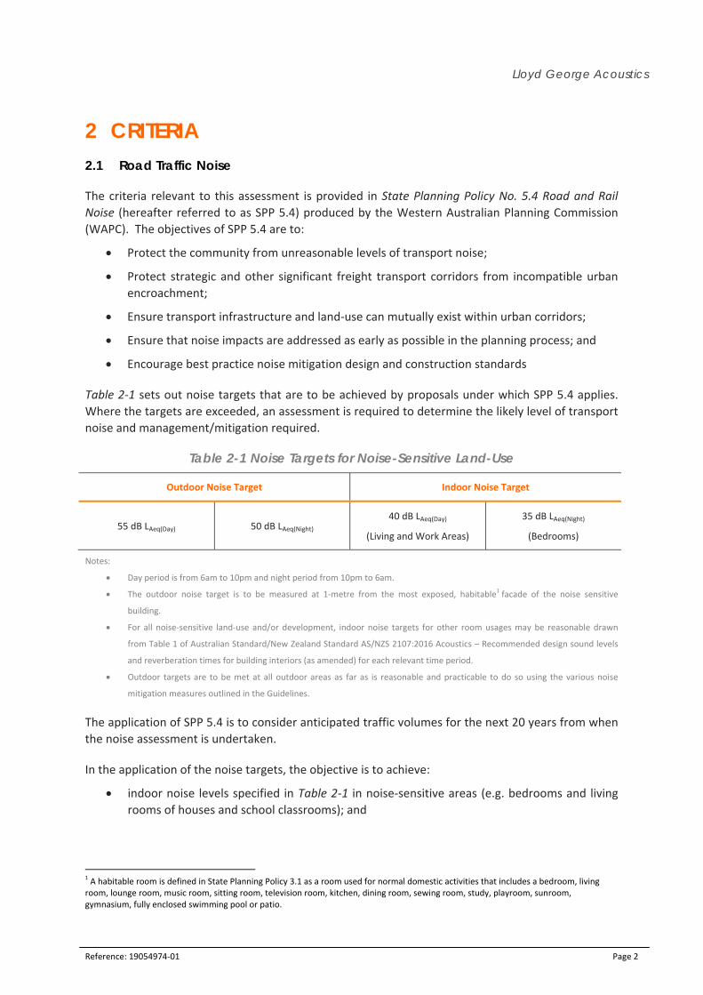
2 CRITERIA 2.1 Road Traffic Noise
The criteria relevant to this assessment is provided in State Planning Policy No. 5.4 Road and Rail
Noise (hereafter referred to as SPP 5.4) produced by the Western Australian Planning Commission
(WAPC). The objectives of SPP 5.4 are to:
Protect the community from unreasonable levels of transport noise;
Protect strategic and other significant freight transport corridors from incompatible urban
encroachment;
Ensure transport infrastructure and land‐use can mutually exist within urban corridors;
Ensure that noise impacts are addressed as early as possible in the planning process; and
Encourage best practice noise mitigation design and construction standards
Table 2‐1 sets out noise targets that are to be achieved by proposals under which SPP 5.4 applies.
Where the targets are exceeded, an assessment is required to determine the likely level of transport
noise and management/mitigation required.
Table 2-1 Noise Targets for Noise-Sensitive Land-Use
Outdoor Noise Target Indoor Noise Target
55 dB LAeq(Day) 50 dB LAeq(Night) 40 dB LAeq(Day)
(Living and Work Areas)
35 dB LAeq(Night)
(Bedrooms)
Notes:
Day period is from 6am to 10pm and night period from 10pm to 6am.
The outdoor noise target is to be measured at 1‐metre from the most exposed, habitable1 facade of the noise sensitive
building.
For all noise‐sensitive land‐use and/or development, indoor noise targets for other room usages may be reasonable drawn
from Table 1 of Australian Standard/New Zealand Standard AS/NZS 2107:2016 Acoustics – Recommended design sound levels
and reverberation times for building interiors (as amended) for each relevant time period.
Outdoor targets are to be met at all outdoor areas as far as is reasonable and practicable to do so using the various noise
mitigation measures outlined in the Guidelines.
The application of SPP 5.4 is to consider anticipated traffic volumes for the next 20 years from when
the noise assessment is undertaken.
In the application of the noise targets, the objective is to achieve:
indoor noise levels specified in Table 2‐1 in noise‐sensitive areas (e.g. bedrooms and living
rooms of houses and school classrooms); and
1 A habitable room is defined in State Planning Policy 3.1 as a room used for normal domestic activities that includes a bedroom, living room, lounge room, music room, sitting room, television room, kitchen, dining room, sewing room, study, playroom, sunroom, gymnasium, fully enclosed swimming pool or patio.

Reference:
It is rec
outdoor
be imple
accepta
2.2 A
The rele
is State
Western
land wit
and the
In this i
Frame.
19054974‐01
a reasonable
non‐residen
the design o
ognised that
r noise targe
emented tha
ble noise pro
Aircraft Nois
evant plannin
Planning Po
n Australian
thin the ‘Fram
Kwinana Fre
Areas below
Areas betwe
Areas above
nstance, the
e degree of a
tial noise‐se
of outdoor ar
t in some in
ts. Where t
at balance r
otection outc
se
ng policy in W
olicy 5.3: La
Planning Co
me’ area, de
eeway as sho
w 20 ANEF;
een 20 ANEF
e 25 ANEF.
e subject site
Figure 2-
Site
acoustic ame
ensitive deve
reas should t
nstances, it m
transport no
easonable a
comes.
Western Aus
nd Use Plan
ommission (h
efined by Ro
own in Figure
and 25 ANE
e is outside
1 Site Loca
enity for out
elopments,
take into con
may not be
ise is above
and practicab
stralia in rela
nning in the
hereafter ref
e Highway, R
e 2‐1. SPP 5
EF; and
the 20 ANE
ality in Rela
tdoor living a
for example
nsideration t
reasonable
the noise ta
ble consider
ation to airc
Vicinity of J
ferred to as
Ranford Roa
.3 defines 3
EF contour (r
ation to Fra
areas on eac
e schools an
he noise targ
and/or prac
argets, meas
ations with
craft noise fr
Jandakot Air
SPP 5.3). SP
d, Warton R
noise exposu
refer Figure
ame Area
Lloyd Geor
h residential
nd childcare
get.
cticable to m
ures are exp
the need to
rom Jandako
rport; Janua
PP 5.3 applie
Road, Armad
ure zones be
2‐2), but w
rge Acousti
Page 3
l lot. For
centres,
meet the
pected to
o achieve
t Airport
ary 2017,
es to any
ale Road
eing:
ithin the
ics
3

Lloyd George Acoustics
Reference: 19054974‐01 Page 4
Figure 2-2 Site Locality in Relation to ANEF Contours
3 METHODOLOGY Noise modelling has been undertaken generally in accordance with the requirements of SPP 5.4 and
associated Guidelines2 as described in the following sections. Lloyd George Acoustics has been
involved with the Armadale Road Upgrade (ARU) and the Armadale Road North Lake Road (ARNLR)
projects and thus information from these reports has been used for the purposes of this assessment.
As the noise model has been adapted from nearby road upgrade project data, it is already calibrated
by noise measurement data.
The computer programme SoundPLAN 8.1 was utilised incorporating the Calculation of Road Traffic
Noise (CoRTN) algorithms, modified to reflect Australian conditions. The modifications included the
following:
Vehicles were separated into heavy (Austroads Class 3 upwards) and non‐heavy (Austroads
Classes 1 & 2) with non‐heavy vehicles having a source height of 0.5 metres above road level
and heavy vehicles having two sources, at heights of 1.5 metres and 3.6 metres above road
level, to represent the engine and exhaust respectively. By splitting the noise source into
2 Road and Rail Noise Guidelines, September 2019
Lloyd George Acoustics
Reference: 19054974‐01 Page 5
three, allows for less barrier attenuation for high level sources where barriers are to be
considered.
Note that a ‐8.0 dB correction is applied to the exhaust and ‐0.8 dB to the engine (based on
Transportation Noise Reference Book, Paul Nelson, 1987), so as to provide consistent results
with the CoRTN algorithms for the no barrier scenario;
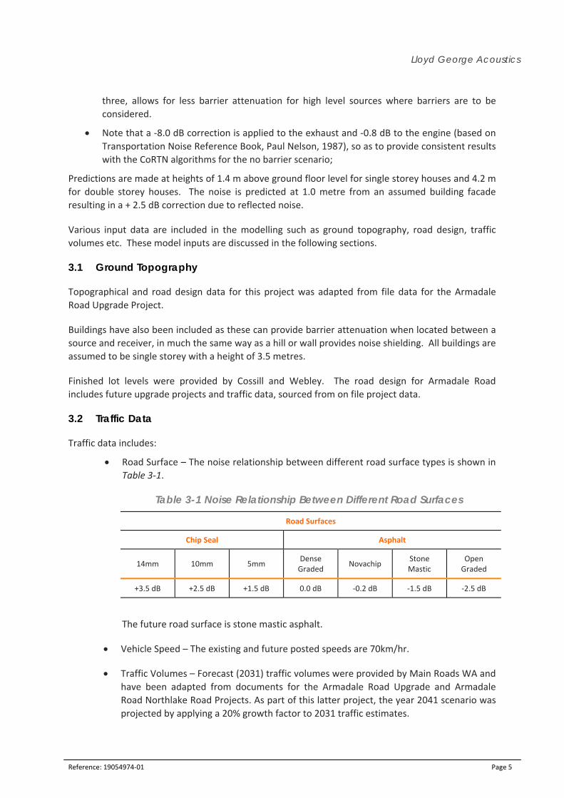
Predictions are made at heights of 1.4 m above ground floor level for single storey houses and 4.2 m
for double storey houses. The noise is predicted at 1.0 metre from an assumed building facade
resulting in a + 2.5 dB correction due to reflected noise.
Various input data are included in the modelling such as ground topography, road design, traffic
volumes etc. These model inputs are discussed in the following sections.
3.1 Ground Topography
Topographical and road design data for this project was adapted from file data for the Armadale
Road Upgrade Project.
Buildings have also been included as these can provide barrier attenuation when located between a
source and receiver, in much the same way as a hill or wall provides noise shielding. All buildings are
assumed to be single storey with a height of 3.5 metres.
Finished lot levels were provided by Cossill and Webley. The road design for Armadale Road
includes future upgrade projects and traffic data, sourced from on file project data.
3.2 Traffic Data
Traffic data includes:
Road Surface – The noise relationship between different road surface types is shown in
Table 3‐1.
Table 3-1 Noise Relationship Between Different Road Surfaces
Road Surfaces
Chip Seal Asphalt
14mm 10mm 5mm Dense Graded
Novachip Stone Mastic
Open Graded
+3.5 dB +2.5 dB +1.5 dB 0.0 dB ‐0.2 dB ‐1.5 dB ‐2.5 dB
The future road surface is stone mastic asphalt.
Vehicle Speed – The existing and future posted speeds are 70km/hr.
Traffic Volumes – Forecast (2031) traffic volumes were provided by Main Roads WA and
have been adapted from documents for the Armadale Road Upgrade and Armadale
Road Northlake Road Projects. As part of this latter project, the year 2041 scenario was
projected by applying a 20% growth factor to 2031 traffic estimates.
Lloyd George Acoustics
Reference: 19054974‐01 Page 6
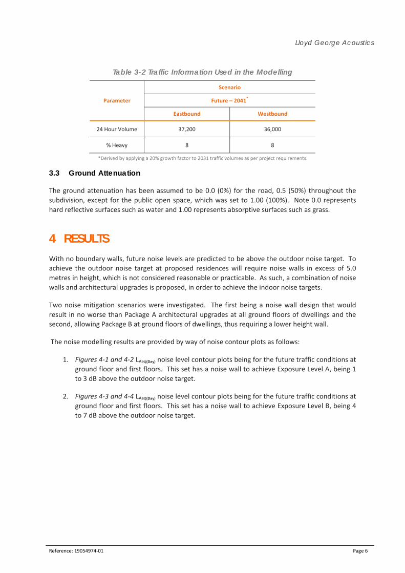
Table 3-2 Traffic Information Used in the Modelling
Parameter
Scenario
Future – 2041*
Eastbound Westbound
24 Hour Volume 37,200 36,000
% Heavy 8 8
*Derived by applying a 20% growth factor to 2031 traffic volumes as per project requirements.
3.3 Ground Attenuation
The ground attenuation has been assumed to be 0.0 (0%) for the road, 0.5 (50%) throughout the
subdivision, except for the public open space, which was set to 1.00 (100%). Note 0.0 represents
hard reflective surfaces such as water and 1.00 represents absorptive surfaces such as grass.
4 RESULTS With no boundary walls, future noise levels are predicted to be above the outdoor noise target. To
achieve the outdoor noise target at proposed residences will require noise walls in excess of 5.0
metres in height, which is not considered reasonable or practicable. As such, a combination of noise
walls and architectural upgrades is proposed, in order to achieve the indoor noise targets.
Two noise mitigation scenarios were investigated. The first being a noise wall design that would
result in no worse than Package A architectural upgrades at all ground floors of dwellings and the
second, allowing Package B at ground floors of dwellings, thus requiring a lower height wall.
The noise modelling results are provided by way of noise contour plots as follows:
1. Figures 4‐1 and 4‐2 LAeq(Day) noise level contour plots being for the future traffic conditions at
ground floor and first floors. This set has a noise wall to achieve Exposure Level A, being 1
to 3 dB above the outdoor noise target.
2. Figures 4‐3 and 4‐4 LAeq(Day) noise level contour plots being for the future traffic conditions at
ground floor and first floors. This set has a noise wall to achieve Exposure Level B, being 4
to 7 dB above the outdoor noise target.
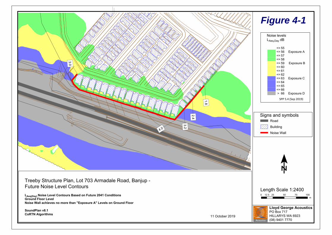
Figure 4-1Noise levelsLAeq,Day dB
<= 55<= 56 Exposure A<= 57 <= 58 <= 59 Exposure B<= 60 <= 61<= 62<= 63 Exposure C<= 64<= 65<= 66> 66 Exposure D
SPP 5.4 (Sep 2019)
Lloyd George AcousticsPO Box 717HILLARYS WA 6923(08) 9401 7770
1.8
2.4
3.2
4.0
3.0
Length Scale 1:24000 12.5 25 50 75 100
m
Treeby Structure Plan, Lot 703 Armadale Road, Banjup -Future Noise Level Contours
LAeq(Day) Noise Level Contours Based on Future 2041 ConditionsGround Floor LevelNoise Wall achieves no more than "Exposure A" Levels on Ground Floor
SoundPlan v8.1CoRTN Algorithms
Signs and symbolsRoad
Building
Noise Wall
11 October 2019
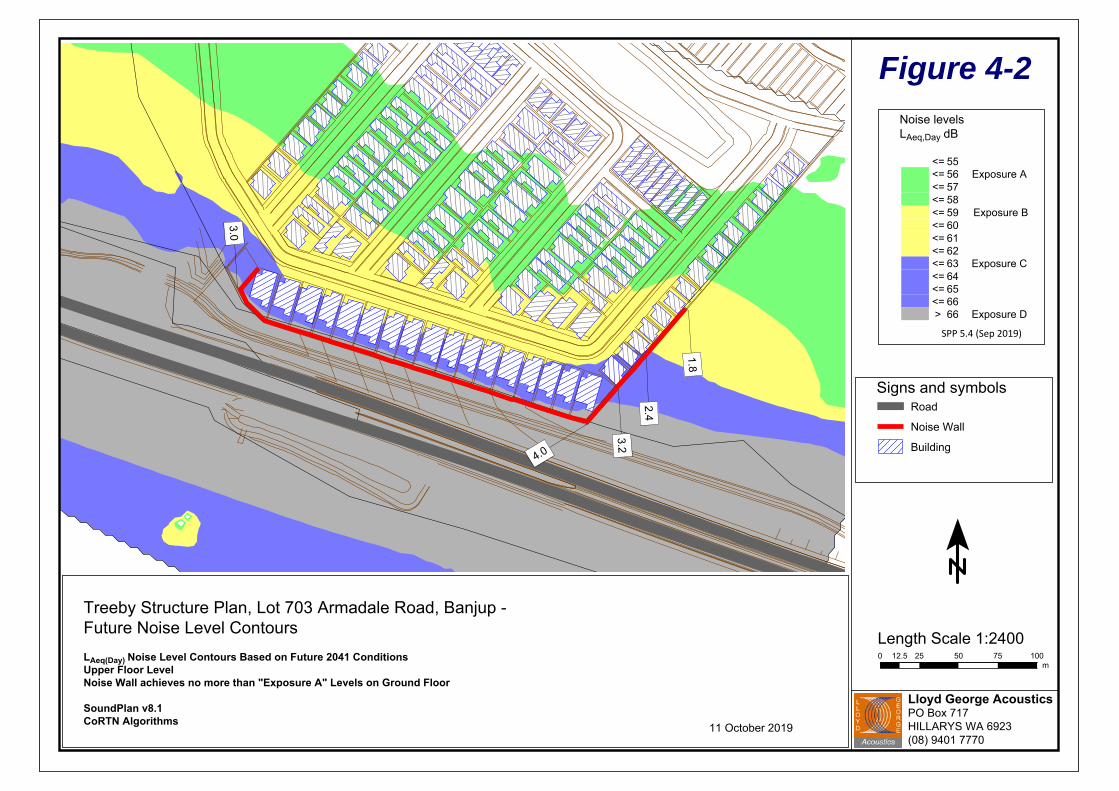
Figure 4-2Noise levelsLAeq,Day dB
<= 55<= 56 Exposure A<= 57 <= 58 <= 59 Exposure B<= 60 <= 61<= 62<= 63 Exposure C<= 64<= 65<= 66> 66 Exposure D
SPP 5.4 (Sep 2019)
Lloyd George AcousticsPO Box 717HILLARYS WA 6923(08) 9401 7770
1.8
2.4
3.2
4.0
3.0
Length Scale 1:24000 12.5 25 50 75 100
m
Treeby Structure Plan, Lot 703 Armadale Road, Banjup -Future Noise Level Contours
LAeq(Day) Noise Level Contours Based on Future 2041 ConditionsUpper Floor LevelNoise Wall achieves no more than "Exposure A" Levels on Ground Floor
SoundPlan v8.1CoRTN Algorithms
Signs and symbolsRoad
Noise Wall
Building
11 October 2019
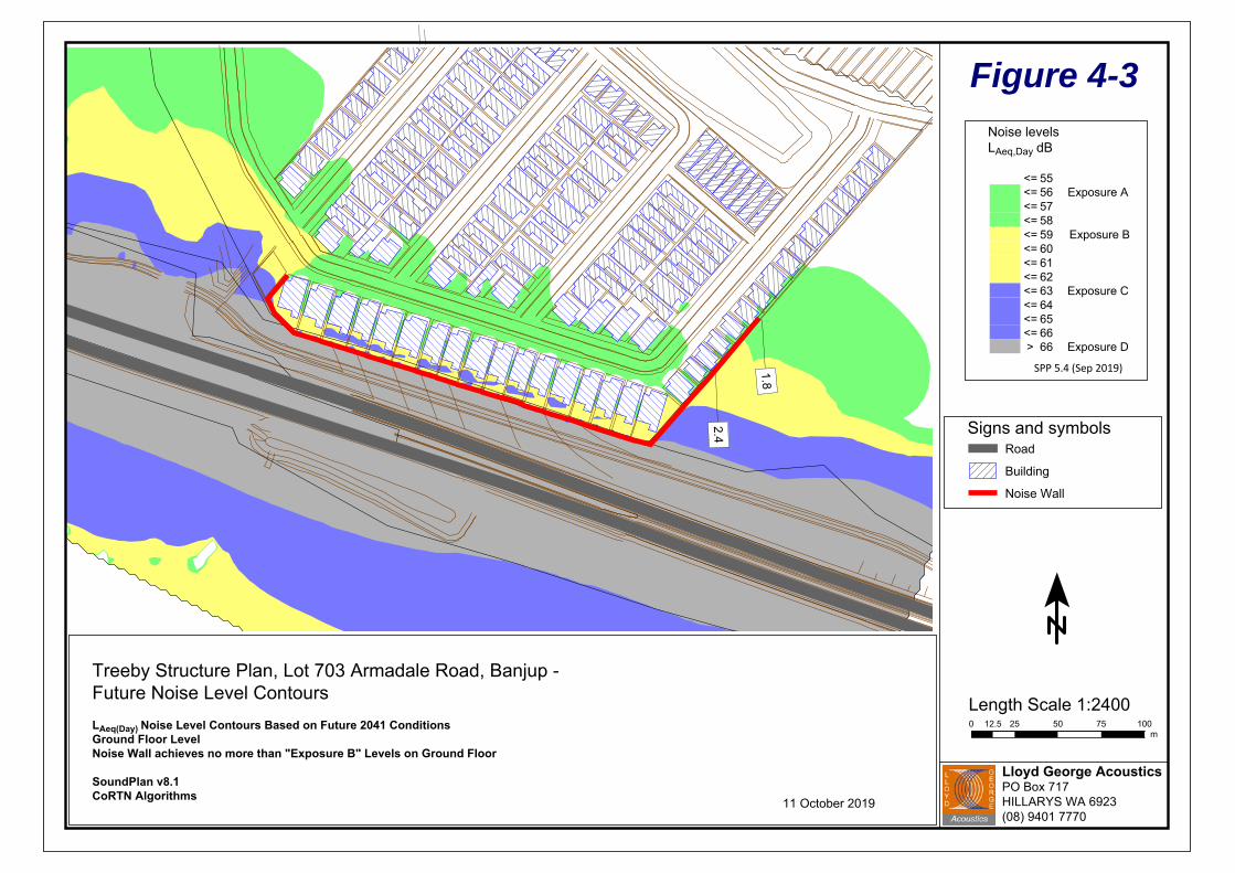
Figure 4-3Noise levelsLAeq,Day dB
<= 55<= 56 Exposure A<= 57 <= 58 <= 59 Exposure B<= 60 <= 61<= 62<= 63 Exposure C<= 64<= 65<= 66> 66 Exposure D
SPP 5.4 (Sep 2019)
Lloyd George AcousticsPO Box 717HILLARYS WA 6923(08) 9401 7770
1.8
2.4
Length Scale 1:24000 12.5 25 50 75 100
m
Treeby Structure Plan, Lot 703 Armadale Road, Banjup -Future Noise Level Contours
LAeq(Day) Noise Level Contours Based on Future 2041 ConditionsGround Floor LevelNoise Wall achieves no more than "Exposure B" Levels on Ground Floor
SoundPlan v8.1CoRTN Algorithms
Signs and symbolsRoad
Building
Noise Wall
11 October 2019

Figure 4-4Noise levelsLAeq,Day dB
<= 55<= 56 Exposure A<= 57 <= 58 <= 59 Exposure B<= 60 <= 61<= 62<= 63 Exposure C<= 64<= 65<= 66> 66 Exposure D
SPP 5.4 (Sep 2019)
Lloyd George AcousticsPO Box 717HILLARYS WA 6923(08) 9401 7770
1.8
2.4
Length Scale 1:24000 12.5 25 50 75 100
m
Treeby Structure Plan, Lot 703 Armadale Road, Banjup -Future Noise Level Contours
LAeq(Day) Noise Level Contours Based on Future 2041 ConditionsUpper Floor LevelNoise Wall achieves no more than "Exposure B" Levels on Ground Floor
SoundPlan v8.1CoRTN Algorithms
Signs and symbolsRoad
Noise Wall
Building
11 October 2019

Lloyd George Acoustics
Reference: 19054974‐01 Page 11
5 ASSESSMENT 5.1 Road Traffic Noise
The objectives of SPP 5.4 are to achieve:
indoor noise levels specified in Table 2‐1 in noise‐sensitive areas (e.g. bedrooms and living
rooms of houses and school classrooms); and
a reasonable degree of acoustic amenity for outdoor living areas on each residential lot.
Where the outdoor noise targets of Table 2‐1 are achieved, no further controls are necessary.
With reference to the predicted noise levels in Section 4, it is evident the outdoor noise target will
be exceeded. As such, one of the following two mitigation options, being combinations of noise
barriers and facade treatments are recommended.
Mitigation Option 1: Achieves ”Exposure A” Level
Construct a noise wall as shown in Figure 5‐1. The noise wall is to be solid, free of gaps and
of minimum surface mass 15kg/m2.
Adopt Packages A, B or C (Refer Appendix A) as dictated in Figures 5‐1 to 5‐2 for ground and
upper floors, respectively, noting ground floors are Package A only.
Alternative constructions from the deemed to satisfy packages may be acceptable if
supported by a report undertaken by a suitably qualified acoustical consultant (member
from of the Association of Australasian Acoustical Consultants (AAAC)), once the lots specific
building plans are available.
Mitigation Option 2: Achieves “Exposure B” Level
Construct a noise wall as shown in Figure 5‐3. The noise wall is to be solid, free of gaps and
of minimum surface mass 15kg/m2.
Adopt Packages A, B or C (Refer Appendix A) as dictated in Figures 5‐3 to 5‐4 for ground and
upper floors, respectively, noting ground floor now increases to Package B in some
instances.
Alternative constructions from the deemed to satisfy packages may be acceptable if
supported by a report undertaken by a suitably qualified acoustical consultant (member
from of the Association of Australasian Acoustical Consultants (AAAC)), once the lots specific
building plans are available.
All affected lots are to have notifications on lot titles as per SPP 5.4 requirements – refer Appendix A.
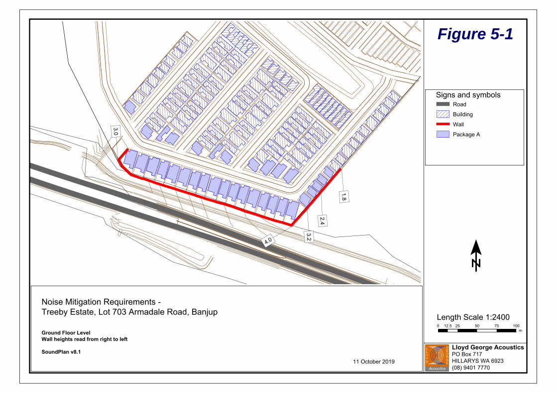
Figure 5-1
Lloyd George AcousticsPO Box 717HILLARYS WA 6923(08) 9401 7770
1.8
2.4
3.24.0
3.0
Length Scale 1:24000 12.5 25 50 75 100
m
Noise Mitigation Requirements -Treeby Estate, Lot 703 Armadale Road, Banjup
Ground Floor LevelWall heights read from right to left
SoundPlan v8.1
Signs and symbolsRoad
Building
Wall
Package A
11 October 2019
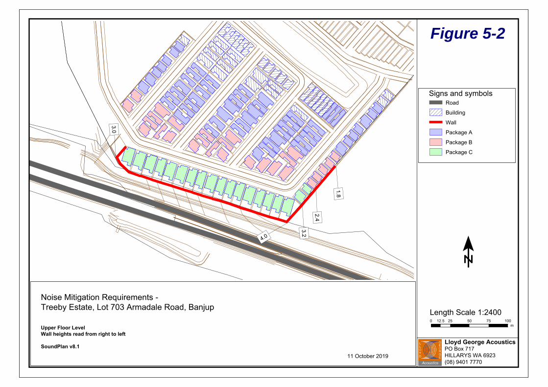
Figure 5-2
Lloyd George AcousticsPO Box 717HILLARYS WA 6923(08) 9401 7770
1.8
2.4
3.24.0
3.0
Length Scale 1:24000 12.5 25 50 75 100
m
Noise Mitigation Requirements -Treeby Estate, Lot 703 Armadale Road, Banjup
Upper Floor LevelWall heights read from right to left
SoundPlan v8.1
Signs and symbolsRoad
Building
Wall
Package A
Package B
Package C
11 October 2019

Figure 5-3
Lloyd George AcousticsPO Box 717HILLARYS WA 6923(08) 9401 7770
1.8
2.4
Length Scale 1:24000 12.5 25 50 75 100
m
Noise Mitigation Requirements -Treeby Estate, Lot 821 Armadale Road, Banjup
Ground Floor LevelWall heights read from right to left
SoundPlan v8.1
Signs and symbolsRoad
Building
Wall
Package A
Package B
11 October 2019

Figure 5-4
Lloyd George AcousticsPO Box 717HILLARYS WA 6923(08) 9401 7770
1.8
2.4
Length Scale 1:24000 12.5 25 50 75 100
m
Noise Mitigation Requirements -Treeby Estate, Lot 703 Armadale Road, Banjup
Upper Floor LevelWall heights read from right to left
SoundPlan v8.1
Signs and symbolsRoad
Building
Wall
Package A
Package B
Package C
11 October 2019
Lloyd George Acoustics
Reference: 19054974‐01 Page 16
5.2 Jandakot Aircraft Noise
With the site being within the Frame Area but outside the 20 ANEF contour, there are no specific
noise mitigation requirements, however SPP 5.3 does require the following:
A notification on title is required, similar to that for road traffic, stating the property is
situated in the vicinity of Jandakot Airport and is currently affected, or may be affected in
the future by aircraft noise. Noise exposure levels are likely to increase in the future as a
result of an increase in the aircraft using the airport, changes in aircraft type, or other
operational changes.
Residents should be aware that thicker glass will perform better acoustically as will
awning/casement style windows in comparison to sliding windows. The benefit of such
windows will require them to be closed and as such, forced ventilation can be considered.
These noise controls are not mandatory but for advice only.

Lloyd George Acoustics
Appendix A
ACCEPTABLE TREATMENT PACKAGES
Lloyd George Acoustics
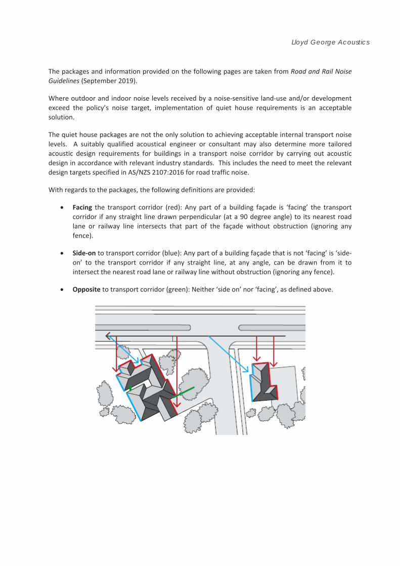
The packages and information provided on the following pages are taken from Road and Rail Noise
Guidelines (September 2019).
Where outdoor and indoor noise levels received by a noise‐sensitive land‐use and/or development
exceed the policy’s noise target, implementation of quiet house requirements is an acceptable
solution.
The quiet house packages are not the only solution to achieving acceptable internal transport noise
levels. A suitably qualified acoustical engineer or consultant may also determine more tailored
acoustic design requirements for buildings in a transport noise corridor by carrying out acoustic
design in accordance with relevant industry standards. This includes the need to meet the relevant
design targets specified in AS/NZS 2107:2016 for road traffic noise.
With regards to the packages, the following definitions are provided:
Facing the transport corridor (red): Any part of a building façade is ‘facing’ the transport
corridor if any straight line drawn perpendicular (at a 90 degree angle) to its nearest road
lane or railway line intersects that part of the façade without obstruction (ignoring any
fence).
Side‐on to transport corridor (blue): Any part of a building façade that is not ‘facing’ is ‘side‐
on’ to the transport corridor if any straight line, at any angle, can be drawn from it to
intersect the nearest road lane or railway line without obstruction (ignoring any fence).
Opposite to transport corridor (green): Neither ‘side on’ nor ‘facing’, as defined above.

Lloyd George Acoustics
Quiet House Package A 56‐58 dB LAeq(Day) & 51‐53 dB LAeq(Night)
Element Orientation Room
Bedroom Indoor Living and Work Areas
External Windows
Facing
Up to 40% floor area (Rw + Ctr ≥ 28):
o Sliding or double hung with minimum 10mm single or 6mm‐12mm‐10mm double insulated glazing;
o Sealed awning or casement windows with minimum 6mm glass.
Up to 60% floor area (Rw + Ctr ≥ 31):
o Sealed awning or casement windows with minimum 6mm glass.
Up to 40% floor area (Rw + Ctr ≥ 25):
o Sliding or double hung with minimum 6mm single or 6mm‐12mm‐6mm double insulated glazing;
Up to 60% floor area (Rw + Ctr ≥ 28);
Up to 80% floor area (Rw + Ctr ≥ 31).
Side On As above, except Rw + Ctr values may be 3 dB less or max % area increased by 20%.
Opposite No specific requirements
External Doors
Facing
Fully glazed hinged door with certified Rw + Ctr ≥ 28 rated door and frame including seals and 6mm glass.
Doors to achieve Rw + Ctr ≥ 25:
o 35mm Solid timber core hinged door and frame system certified to Rw 28 including seals;
o Glazed sliding door with 10mm glass and weather seals.
Side On As above, except Rw + Ctr values may be 3 dB less.
Opposite No specific requirements
External Walls
All
Rw + Ctr ≥ 45:
o Two leaves of 90mm thick clay brick masonry with minimum 20mm cavity;
o Single leaf of 150mm brick masonry with 13mm cement render on each face.
o One row of 92mm studs at 600mm centres with:
Resilient steel channels fixed to the outside of the studs; and
9.5mm hardboard or fibre cement sheeting or 11mm fibre cement weatherboards fixed to the outside;
75mm thick mineral wool insulation with a density of at least 11kgkg/m3; and
2 x 16mm fire‐rated plasterboard to inside.
Roofs and Ceilings
All
Rw + Ctr ≥ 35:
o Concrete or terracotta tile or metal sheet roof with sarking and at least 10mm plasterboard.
Outdoor Living Areas At least one outdoor living area located on the opposite side of the building from the transport corridor and/or at least one ground level outdoor living area screened using a solid continuous fence or other structure of minimum 2 metres height above ground level.
Lloyd George Acoustics
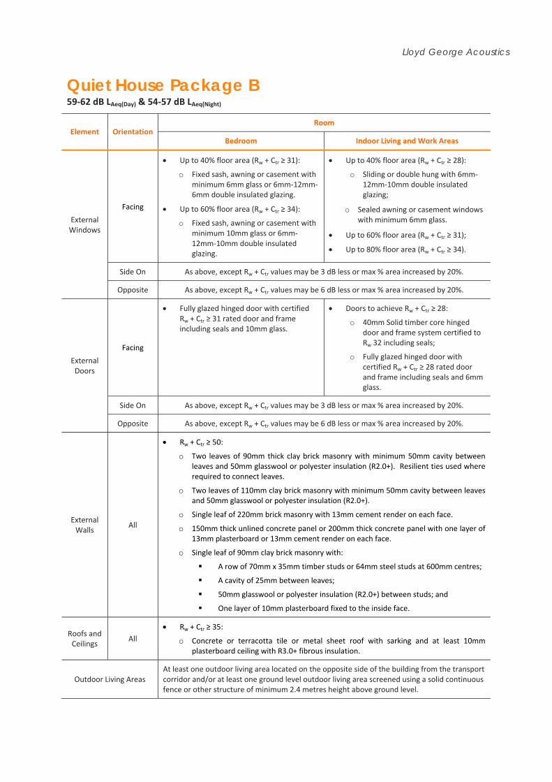
Quiet House Package B 59‐62 dB LAeq(Day) & 54‐57 dB LAeq(Night)
Element Orientation Room
Bedroom Indoor Living and Work Areas
External Windows
Facing
Up to 40% floor area (Rw + Ctr ≥ 31):
o Fixed sash, awning or casement with minimum 6mm glass or 6mm‐12mm‐6mm double insulated glazing.
Up to 60% floor area (Rw + Ctr ≥ 34):
o Fixed sash, awning or casement with minimum 10mm glass or 6mm‐12mm‐10mm double insulated glazing.
Up to 40% floor area (Rw + Ctr ≥ 28):
o Sliding or double hung with 6mm‐12mm‐10mm double insulated glazing;
o Sealed awning or casement windows with minimum 6mm glass.
Up to 60% floor area (Rw + Ctr ≥ 31);
Up to 80% floor area (Rw + Ctr ≥ 34).
Side On As above, except Rw + Ctr values may be 3 dB less or max % area increased by 20%.
Opposite As above, except Rw + Ctr values may be 6 dB less or max % area increased by 20%.
External Doors
Facing
Fully glazed hinged door with certified Rw + Ctr ≥ 31 rated door and frame including seals and 10mm glass.
Doors to achieve Rw + Ctr ≥ 28:
o 40mm Solid timber core hinged door and frame system certified to Rw 32 including seals;
o Fully glazed hinged door with certified Rw + Ctr ≥ 28 rated door and frame including seals and 6mm glass.
Side On As above, except Rw + Ctr values may be 3 dB less or max % area increased by 20%.
Opposite As above, except Rw + Ctr values may be 6 dB less or max % area increased by 20%.
External Walls
All
Rw + Ctr ≥ 50:
o Two leaves of 90mm thick clay brick masonry with minimum 50mm cavity between leaves and 50mm glasswool or polyester insulation (R2.0+). Resilient ties used where required to connect leaves.
o Two leaves of 110mm clay brick masonry with minimum 50mm cavity between leaves and 50mm glasswool or polyester insulation (R2.0+).
o Single leaf of 220mm brick masonry with 13mm cement render on each face.
o 150mm thick unlined concrete panel or 200mm thick concrete panel with one layer of 13mm plasterboard or 13mm cement render on each face.
o Single leaf of 90mm clay brick masonry with:
A row of 70mm x 35mm timber studs or 64mm steel studs at 600mm centres;
A cavity of 25mm between leaves;
50mm glasswool or polyester insulation (R2.0+) between studs; and
One layer of 10mm plasterboard fixed to the inside face.
Roofs and Ceilings
All
Rw + Ctr ≥ 35:
o Concrete or terracotta tile or metal sheet roof with sarking and at least 10mm plasterboard ceiling with R3.0+ fibrous insulation.
Outdoor Living Areas At least one outdoor living area located on the opposite side of the building from the transport corridor and/or at least one ground level outdoor living area screened using a solid continuous fence or other structure of minimum 2.4 metres height above ground level.

Lloyd George Acoustics
Quiet House Package C 63‐66 dB LAeq(Day) & 58‐61 dB LAeq(Night)
Element Orientation Room
Bedroom Indoor Living and Work Areas
External Windows
Facing
Up to 20% floor area (Rw + Ctr ≥ 31):
o Fixed sash, awning or casement with minimum 6mm glass or 6mm‐12mm‐6mm double insulated glazing.
Up to 40% floor area (Rw + Ctr ≥ 34):
o Fixed sash, awning or casement with minimum 10mm glass or 6mm‐12mm‐10mm double insulated glazing.
Up to 40% floor area (Rw + Ctr ≥ 31):
o Fixed sash, awning or casement with minimum 6mm glass or 6mm‐12mm‐6mm double insulated glazing.
Up to 60% floor area (Rw + Ctr ≥ 34):
o Fixed sash, awning or casement with minimum 10mm glass or 6mm‐12mm‐10mm double insulated glazing.
Side On As above, except Rw + Ctr values may be 3 dB less or max % area increased by 20%.
Opposite As above, except Rw + Ctr values may be 6 dB less or max % area increased by 20%.
External Doors
Facing
Not recommended. Doors to achieve Rw + Ctr ≥ 30:
o Fully glazed hinged door with certified Rw + Ctr ≥ 31 rated door and frame including seals and 10mm glass;
o 40mm Solid timber core side hinged door, frame and seal system certified to Rw 32 including seals. Any glass inserts to be minimum 6mm.
Side On As above, except Rw + Ctr values may be 3 dB less or max % area increased by 20%.
Opposite As above, except Rw + Ctr values may be 6 dB less or max % area increased by 20%.
External Walls
All
Rw + Ctr ≥ 50:
o Two leaves of 90mm thick clay brick masonry with minimum 50mm cavity between leaves and 50mm glasswool or polyester insulation (R2.0+). Resilient ties used where required to connect leaves.
o Two leaves of 110mm clay brick masonry with minimum 50mm cavity between leaves and 50mm glasswool or polyester insulation (R2.0+).
o Single leaf of 220mm brick masonry with 13mm cement render on each face.
o 150mm thick unlined concrete panel or 200mm thick concrete panel with one layer of 13mm plasterboard or 13mm cement render on each face.
o Single leaf of 90mm clay brick masonry with:
A row of 70mm x 35mm timber studs or 64mm steel studs at 600mm centres;
A cavity of 25mm between leaves;
50mm glasswool or polyester insulation (R2.0+) between studs; and
One layer of 10mm plasterboard fixed to the inside face.
Roofs and Ceilings
All
Rw + Ctr ≥ 40:
o Concrete or terracotta tile roof with sarking, or metal sheet roof with foil backed R2.0+ fibrous insulation between steel sheeting and roof battens;
o R3.0+ insulation batts above ceiling;
o 2 x 10mm plasterboard ceiling or 1 x 13mm sound‐rated plasterboard.
Outdoor Living Areas At least one outdoor living area located on the opposite side of the building from the transport corridor and/or at least one ground level outdoor living area screened using a solid continuous fence or other structure of minimum 2.4 metres height above ground level.
Lloyd George Acoustics
Mechanical Ventilation requirements
In implementing the acceptable treatment packages, the following mechanical ventilation / air‐
conditioning considerations are required:
Acoustically rated openings and ductwork to provide a minimum sound reduction
performance of Rw 40 dB into sensitive spaces;
Evaporative systems require attenuated ceiling air vents to allow closed windows;
Refrigerant based systems need to be designed to achieve National Construction Code fresh
air ventilation requirements;
Openings such as eaves, vents and air inlets must be acoustically treated, closed or relocated
to building sides facing away from the corridor where practicable.
Notification
Notifications on title advise prospective purchasers of the potential for noise impacts from major
transport corridors and help with managing expectations.
The Notification is to state as follows:
This lot is in the vicinity of a transport corridor and is affected, or may in the future be affected, by
road and rail transport noise. Road and rail transport noise levels may rise or fall over time
depending on the type and volume of traffic.

Lloyd George Acoustics
Appendix B
Terminology

Lloyd George Acoustics
The following is an explanation of the terminology used throughout this report.
Decibel (dB)
The decibel is the unit that describes the sound pressure and sound power levels of a noise source. It
is a logarithmic scale referenced to the threshold of hearing.
A‐Weighting
An A‐weighted noise level has been filtered in such a way as to represent the way in which the
human ear perceives sound. This weighting reflects the fact that the human ear is not as sensitive to
lower frequencies as it is to higher frequencies. An A‐weighted sound level is described as LA dB.
L1
An L1 level is the noise level which is exceeded for 1 per cent of the measurement period and is
considered to represent the average of the maximum noise levels measured.
L10
An L10 level is the noise level which is exceeded for 10 per cent of the measurement period and is
considered to represent the “intrusive” noise level.
L90
An L90 level is the noise level which is exceeded for 90 per cent of the measurement period and is
considered to represent the “background” noise level.
Leq
The Leq level represents the average noise energy during a measurement period.
LA10,18hour
The LA10,18 hour level is the arithmetic average of the hourly LA10 levels between 6.00 am and midnight.
The CoRTN algorithms were developed to calculate this parameter.
LAeq,24hour
The LAeq,24 hour level is the logarithmic average of the hourly LAeq levels for a full day (from midnight to
midnight).
LAeq,8hour / LAeq (Night)
The LAeq (Night) level is the logarithmic average of the hourly LAeq levels from 10.00 pm to 6.00 am on
the same day.
LAeq,16hour / LAeq (Day)
The LAeq (Day) level is the logarithmic average of the hourly LAeq levels from 6.00 am to 10.00 pm on the
same day. This value is typically 1‐3 dB less than the LA10,18hour.
Noise‐sensitive land use and/or development
Land‐uses or development occupied or designed for occupation or use for residential purposes
(including dwellings, residential buildings or short‐stay accommodation), caravan park, camping
ground, educational establishment, child care premises, hospital, nursing home, corrective institution
or place of worship.
Lloyd George Acoustics
About the Term ‘Reasonable’
An assessment of reasonableness should demonstrate that efforts have been made to resolve
conflicts without comprising on the need to protect noise‐sensitive land‐use activities. For example,
have reasonable efforts been made to design, relocate or vegetate a proposed noise barrier to
address community concerns about the noise barrier height? Whether a noise mitigation measure is
reasonable might include consideration of:
The noise reduction benefit provided;
The number of people protected;
The relative cost vs benefit of mitigation;
Road conditions (speed and road surface) significantly differ from noise forecast table
assumptions;
Existing and future noise levels, including changes in noise levels;
Aesthetic amenity and visual impacts;
Compatibility with other planning policies;
Differences between metropolitan and regional situations and whether noise modelling
requirements reflect the true nature of transport movements;
Ability and cost for mobilisation and retrieval of noise monitoring equipment in regional
areas;
Differences between Greenfield and infill development;
Differences between freight routes and public transport routes and urban corridors;
The impact on the operational capacity of freight routes;
The benefits arising from the proposed development;
Existing or planned strategies to mitigate the noise at source.
About the Term ‘Practicable’
‘Practicable’ considerations for the purposes of the policy normally relate to the engineering aspects
of the noise mitigation measures under evaluation. It is defined as “reasonably practicable having
regard to, among other things, local conditions and circumstances (including costs) and to the
current state of technical knowledge” (Environmental Protection Act 1986). These may include:
Limitations of the different mitigation measures to reduce transport noise;
Competing planning policies and strategies;
Safety issues (such as impact on crash zones or restrictions on road vision);
Topography and site constraints (such as space limitations);
Engineering and drainage requirements;
Access requirements (for driveways, pedestrian access and the like);
Maintenance requirements;
Bushfire resistance or BAL ratings;
Suitability of the building for acoustic treatments.
Rw
This is the weighted sound reduction index and is similar to the previously used STC (Sound
Transmission Class) value. It is a single number rating determined by moving a grading curve in
integral steps against the laboratory measured transmission loss until the sum of the deficiencies at
each one‐third‐octave band, between 100 Hz and 3.15 kHz, does not exceed 32 dB. The higher the
Rw value, the better the acoustic performance.

Lloyd George Acoustics
Ctr
This is a spectrum adaptation term for airborne noise and provides a correction to the Rw value to
suit source sounds with significant low frequency content such as road traffic or home theatre
systems. A wall that provides a relatively high level of low frequency attenuation (i.e. masonry) may
have a value in the order of –4 dB, whilst a wall with relatively poor attenuation at low frequencies
(i.e. stud wall) may have a value in the order of ‐14 dB.
Chart of Noise Level Descriptors
Austroads Vehicle Class

Lloyd George Acoustics
Typical Noise Levels