Embed Size (px)
Citation preview
Low Impact Development Solutions to Reduce Stormwater Run-off
Town of Nags Head
PO Box 99 Nags Head, NC 27954 www.nagsheadnc.gov
North Carolina Coastal Federation
Northeast Regional Office 128 Grenville Street Manteo, NC 27954 www.nccoast.org
First Edition: January, 2014
Subject to updates
Acknowledgements
In 2013, the Town of Nags Head began work with the N.C. Coastal Federation to develop a Low Impact Development manual as a reference document for local citizens and developers as part of Town efforts to improve stormwater management and as a technical resource for application of Town Stormwater regulations. This project is based on the LID manual for the coastal towns of Columbia, Cedar Point and Cape Carteret. The Town of Columbia worked in direct partnership with the N.C. Coastal Federation to complete an LID manual. The Town of Cedar Point worked in partnership with the Town of Cape Carteret, the N.C. Coastal Federation, engineering consultants Withers & Ravenel, N.C. Division of Water Quality and the LID Technical Review Team to complete the Cedar Point/Cape Carteret manual. We would like to thank these three communities and their partners for sharing their work and providing a model for us to follow. At the local level, the following people were involved in the development and review of the updated Stormwater Regulations which are referred to in this manual as well as for several exhibits provided.
Town of Nags Head Board of Commissioners 2012‐13 Mayor Bob Oakes Mayor Pro‐Tem Doug Remaley Commissioner Susie Walters Commissioner Renee Cahoon Commissioner Anna Sadler 2013‐14 Mayor Robert Edwards Mayor Pro‐Tem Susie Walters Commissioner Renee Cahoon Commissioner Marvin Demers Commissioner John Ratzenberger Town of Nags Head Planning Board Marvin Demers Richard Murphy Pogie Worsley Mark Cornwell Bob Edwards Barbara Gernat Clyde Futrell Toni Parker
Special thanks go to David Ryan, P.E., Andy Deel, P.E., and the North Carolina Coastal Federation staff for their contributions to this Manual. UNC Chapel Hill Outer Banks Field Site interns Mark Stripp and Katrina Phillips contributed the photographs.
Town Ordinance Update Committee Marvin Demers Richard Murphy Pogie Worsley Mark Cornwell Bob Edwards Kelly Wyatt, CZO Dabni Shelton, CZO Kim Allen Andy Deel, P.E David Ryan, P.E. Elizabeth Teague, AICP, CTP


TABLE OF CONTENTS
1. Background and Purpose
2. Practices to Manage Stormwater Fact Sheets
3. General Siting Considerations related to Separation Distances
4. Using LID to Comply with Town Stormwater Management Requirements
Application Requirements
Residential BMP Selection Guide for Non‐Engineered BMP'S (For projects using fill amounts of 2' or less)
Residential BMP Selection guide for Engineered BMP'S (For fill amounts of greater than 2') and
Commercial/Multi‐Family BMP Selection guide for Engineered BMP'S
5. Reference Information
Soils Map of Nags Head
The Nags Head Environment
Sources
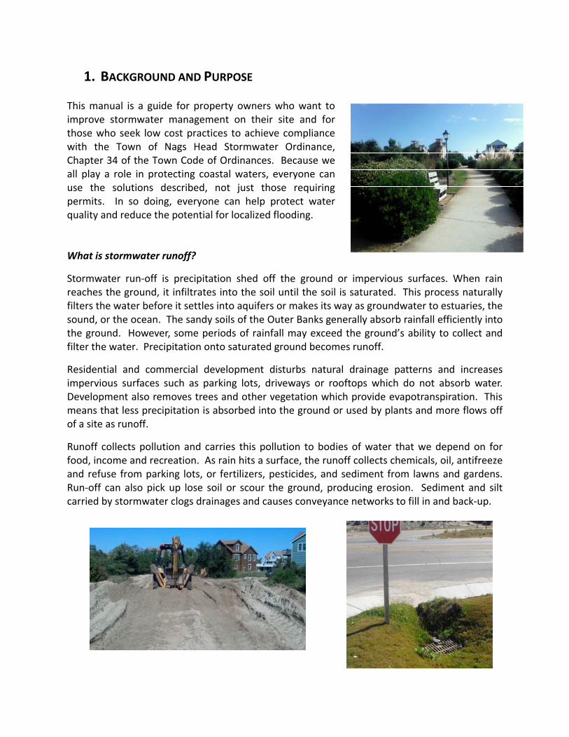
1. BACKGROUND AND PURPOSE This manual is a guide for property owners who want to improve stormwater management on their site and for those who seek low cost practices to achieve compliance with the Town of Nags Head Stormwater Ordinance, Chapter 34 of the Town Code of Ordinances. Because we all play a role in protecting coastal waters, everyone can use the solutions described, not just those requiring permits. In so doing, everyone can help protect water quality and reduce the potential for localized flooding. What is stormwater runoff?
Stormwater run‐off is precipitation shed off the ground or impervious surfaces. When rain reaches the ground, it infiltrates into the soil until the soil is saturated. This process naturally filters the water before it settles into aquifers or makes its way as groundwater to estuaries, the sound, or the ocean. The sandy soils of the Outer Banks generally absorb rainfall efficiently into the ground. However, some periods of rainfall may exceed the ground’s ability to collect and filter the water. Precipitation onto saturated ground becomes runoff.
Residential and commercial development disturbs natural drainage patterns and increases impervious surfaces such as parking lots, driveways or rooftops which do not absorb water. Development also removes trees and other vegetation which provide evapotranspiration. This means that less precipitation is absorbed into the ground or used by plants and more flows off of a site as runoff.
Runoff collects pollution and carries this pollution to bodies of water that we depend on for food, income and recreation. As rain hits a surface, the runoff collects chemicals, oil, antifreeze and refuse from parking lots, or fertilizers, pesticides, and sediment from lawns and gardens. Run‐off can also pick up lose soil or scour the ground, producing erosion. Sediment and silt carried by stormwater clogs drainages and causes conveyance networks to fill in and back‐up.
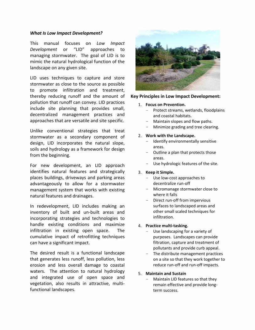
What Is Low Impact Development?
This manual focuses on Low Impact Development or “LID” approaches to managing stormwater. The goal of LID is to mimic the natural hydrological function of the landscape on any given site.
LID uses techniques to capture and store stormwater as close to the source as possible to promote infiltration and treatment, thereby reducing runoff and the amount of pollution that runoff can convey. LID practices include site planning that provides small, decentralized management practices and approaches that are versatile and site specific.
Unlike conventional strategies that treat stormwater as a secondary component of design, LID incorporates the natural slope, soils and hydrology as a framework for design from the beginning.
For new development, an LID approach identifies natural features and strategically places buildings, driveways and parking areas advantageously to allow for a stormwater management system that works with existing natural features and drainages.
In redevelopment, LID includes making an inventory of built and un‐built areas and incorporating strategies and technologies to handle existing conditions and maximize infiltration in existing open space. The cumulative impact of retrofitting techniques can have a significant impact.
The desired result is a functional landscape that generates less runoff, less pollution, less erosion and less overall damage to coastal waters. The attention to natural hydrology and integrated use of open space and vegetation, also results in attractive, multi‐functional landscapes.
Key Principles in Low Impact Development:
1. Focus on Prevention. - Protect streams, wetlands, floodplains
and coastal habitats. - Maintain slopes and flow paths. - Minimize grading and tree clearing.
2. Work with the Landscape. - Identify environmentally sensitive
areas. - Outline a plan that protects those
areas. - Use hydrologic features of the site.
3. Keep it Simple. - Use low‐cost approaches to
decentralize run‐off - Micromanage stormwater close to
where it falls - Direct run‐off from impervious
surfaces to landscaped areas and other small scaled techniques for infiltration.
4. Practice multi‐tasking. - Use landscaping for a variety of
purposes. Landscapes can provide filtration, capture and treatment of pollutants and provide curb appeal.
- The distribute management practices on a site so that they work together to reduce run‐off and run‐off impacts.
5. Maintain and Sustain - Maintain LID features so that they
remain effective and provide long‐term success.
What is a Best Management Practice or BMP? Best Management Practices or “BMPs,” are inter‐changeable terms which describe the techniques implemented to treat or limit pollutants and other damaging effects of stormwater runoff. In North Carolina, these terms are used to describe the techniques implemented in order to meet legislative and North Carolina Administrative Code requirements. The North Carolina Stormwater Best Management Practices Manual or “NCDENR BMP Manual” is the stormwater design manual approved by the North Carolina Division of Water Quality. This document is designed to be a local version of a BMP Manual, providing guidance for practices which can be utilized effectively in the Nags Head environment and to meet the Town’s Stormwater Management requirements. The term best management practice or BMP encompasses two major categories of BMPs: non‐structural and structural. Non‐structural BMPs are typically passive or programmatic and tend to focus on source control and pollution prevention; reducing pollution in runoff by reducing the opportunity for the stormwater runoff to be exposed to pollutants. Structural BMPs refer to physical structures designed to remove pollutants from stormwater runoff, reduce downstream erosion, provide flood control, and promote groundwater recharge. How To Use This Manual:
This Manual provides information in three major areas.
1. Chapters 2 and 3 of this Manual offer a variety of LID “Best Management Practices” (also called “BMPs”) and considerations to keep in mind when choosing which types of practices for different sites. With this guidance, anyone can incorporate one or more practices into their site for improved stormwater management, both in new development and in re‐use of existing developed sites. Practices are described in Chapter 2 with Fact Sheets which are intended for easy reference and to be used individually or together to create a stormwater management strategy for a given project. Each Fact Sheet contains a brief overview of the LID technique, its benefits, information on installation and maintenance, and reference information. Chapter 3 provides additional information on siting the BMP relative to maintaining required distances from septic systems and wetlands.
2. Chapter 4 of the Manual is an overview of the Town’s application requirements for those who have to comply with the Town’s Stormwater Management Ordinance, Chapter 34 of the Town’s Code of Ordinances. These requirements apply to commercial and multi‐family projects and for individual sites of residential development that use fill. While LID techniques are applicable to commercial projects, this Manual will be particularly helpful for individual residential lot development and lays out a step by step approach for developing a stormwater management plan that will comply. Residential development that does not use fill, lot disturbance l imited to site investigations (for the purpose of surveying or determining septic suitability), and land disturbance and fill used in the repair and/or replacement of existing septic systems, are exempt from the Town’s stormwater management requirements, but can still benefit from applying LID techniques.

3. Chapter 5 of the Manual provides reference material regarding the Nags Head environment, soil types, and other useful information. This section also includes sources for additional information and application forms.
Questions regarding this Manual or the Town’s development requirements should be directed to the Town of Nags Head Planning and Development Department, located at 5401 South Croatan Highway in Nags Head, NC, 27959, (252) 441‐7016.
In addition to this Manual, the following are also useful references:
The North Carolina Manual for Stormwater Best Management Practices, available at the NC Division of Water Resources (NCDWR): http://portal.ncdenr.org/web/wq/ws/su/bmp‐manual
The Low Impact Development Guidebook by NC State University, available at: http://www.ces.ncsu.edu/depts/agecon/WECO/lidguidebook/ Stormwater Best Management Practices by the US EPA, available at: http:www.epa.gov/oaintrnt/stormwater/best_practices.htm/
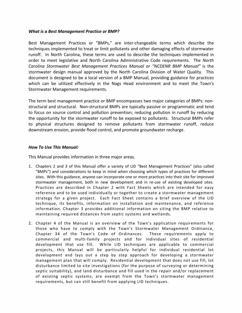
2. BEST MANAGEMENT PRACTICES Site Fingerprinting
What Is Site Fingerprinting?
‐Site Fingerprinting is a practice that uses site design as a stormwater management tool by reducing land disturbance, preserving soil structure, and utilizing suitable natural areas (rather than expensive structural practices for runoff management).
‐Rather than grading land to fit a desired development type, the type of development is dictated by the existing conditions of the site, resulting in developed sites which use the land to maintain and protect the natural balance of the surrounding ecosystem. Did You Know?
‐Site Fingerprinting can be done during the planning process for no additional cost and can often lead to reduced infrastructure costs.
‐By fitting the development to the land, it is often easier to preserve existing vegetation, giving a more established look to new developments.
‐A little preservation goes a long way toward effective stormwater management. Benefits
Reduced stormwater runoff volumes discharged into our waterways
Maintained natural drainage patterns Reduced infrastructure costs Healthier green space
Helpful Hints
When trying to preserve the health of the local watershed, the best place to start is to enhance and preserve the natural stormwater treatment areas. These include marshes, wetlands, and coastal forests, which have great potential to control and treat stormwater runoff.
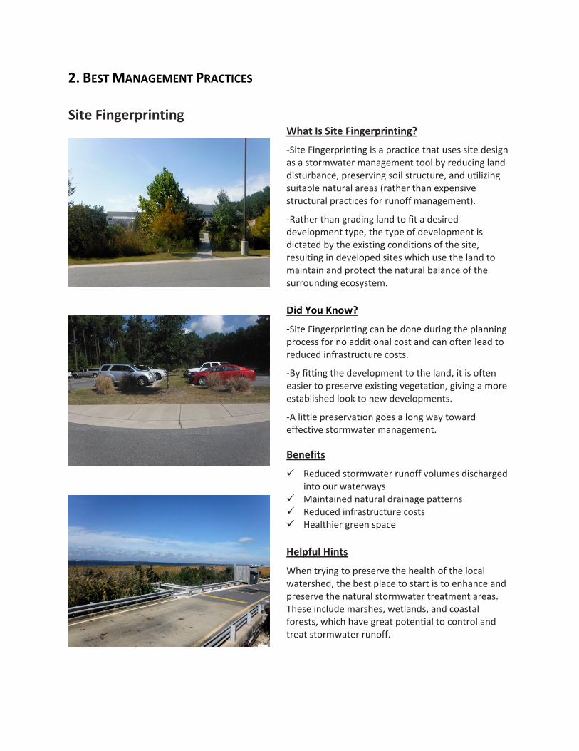
Where to Start
1. Start by identifying the natural characteristics of a site. Conduct “natural resources inventory” of what’s already there. • Wetlands • Shoreline • Floodplain • Forests • Flow patterns
2. Determine site potential for LID stormwater treatment.
• Locate development on least sensitive natural areas • Protect the preservation areas during construction • Use density where appropriate • Minimize soil compaction during construction • Use disconnected impervious areas to minimize
runoff volumes • Use the natural drainage patterns
References and Resources for Site Fingerprinting
Low Impact Development Center: www.lowimpactdevelopment.org
Green Growth Guidelines, Chapters 1‐6, Site Fingerprinting Utilizing GIS/GPS Technology: http://coastalgadnr.org/cm/green/guide
Urban Land Institute: http://www.uli.org/wp‐content/uploads/2012/07/EnvironmentandDev.ashx_.pdf
American Institute of Certified Planners (AICP): www.planning.org ‐ search stormwater
American Society of Landscape Architects (ASLA): www.asla.org ‐ search LID
Ladybird Johnson Wildflower Center: www.wildflower.org ‐ search LID
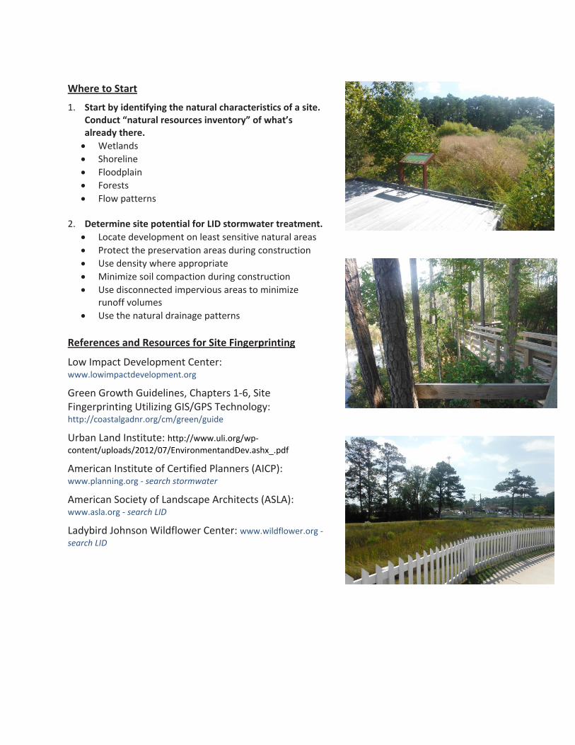
Disconnected Impervious Surfaces
What is a Disconnected Impervious Surface?
‐Roof tops, parking lots, and other impervious surfaces often drain directly to pipe systems or ditches, increasing runoff and preventing rainwater from soaking into the ground.
‐Disconnected impervious areas are those which divert or direct stormwater to naturally vegetated areas.
‐This reduces pollution by slowing down the runoff, increasing infiltration, and filtering flow through vegetation. Did You Know?
‐During small storms, disconnected impervious areas can reduce runoff volume by 30% to 100%.
‐This technique also reduces the need for irrigation, and lower infrastructure costs.
‐This approach spreads multiple practices throughout a site, as opposed to the costs and maintenance problems associated with on large retention pond. Benefits
Reduces stormwater runoff volumes discharged into our waterways
Reduces infrastructure costs
Reduces dependence on irrigation
Provides healthier green space Helpful Hints
‐For the best effect, tie multiple practices together, using disconnected impervious areas as part of a larger stormwater management strategy.
Where to Start
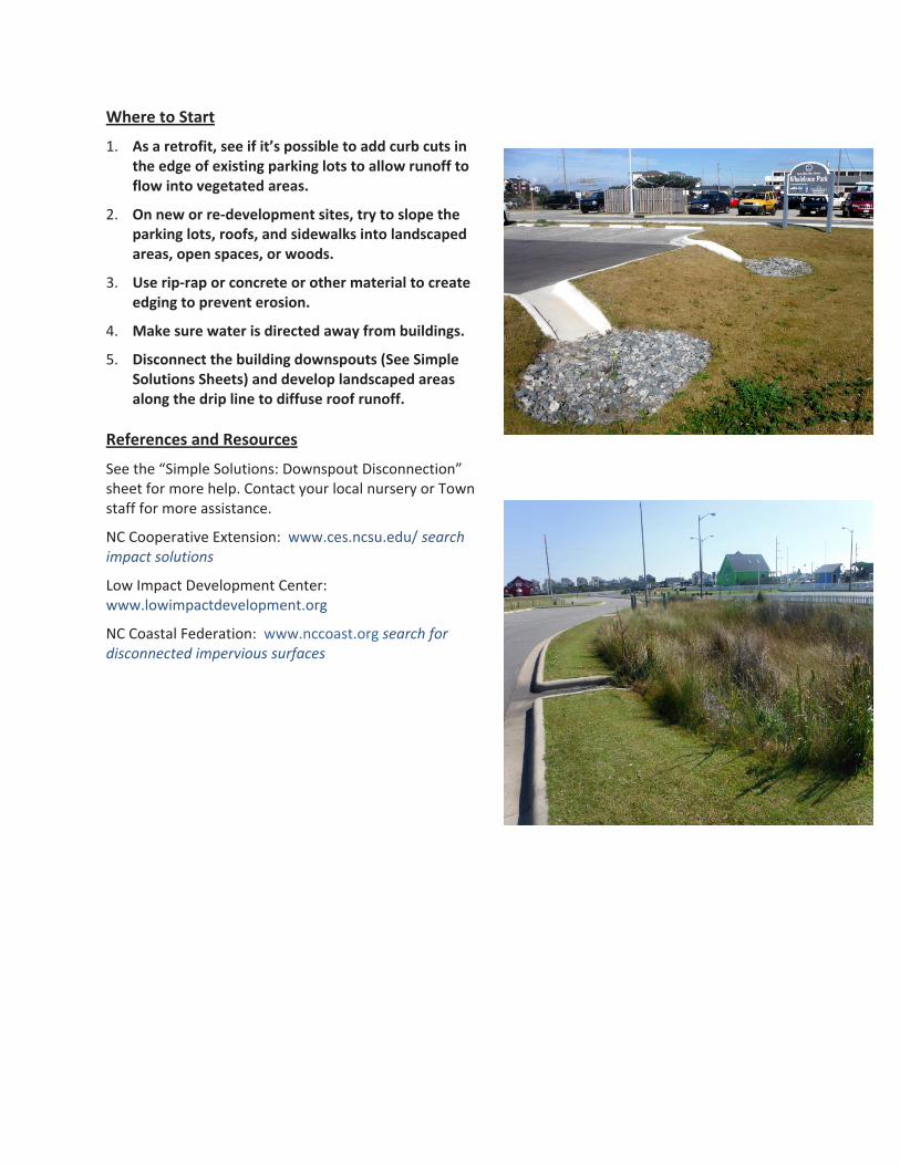
1. As a retrofit, see if it’s possible to add curb cuts in the edge of existing parking lots to allow runoff to flow into vegetated areas.
2. On new or re‐development sites, try to slope the parking lots, roofs, and sidewalks into landscaped areas, open spaces, or woods.
3. Use rip‐rap or concrete or other material to create edging to prevent erosion.
4. Make sure water is directed away from buildings.
5. Disconnect the building downspouts (See Simple Solutions Sheets) and develop landscaped areas along the drip line to diffuse roof runoff.
References and Resources
See the “Simple Solutions: Downspout Disconnection” sheet for more help. Contact your local nursery or Town staff for more assistance.
NC Cooperative Extension: www.ces.ncsu.edu/ search impact solutions
Low Impact Development Center: www.lowimpactdevelopment.org
NC Coastal Federation: www.nccoast.org search for disconnected impervious surfaces

Planter Boxes What is a Planter Box?
‐Planter boxes use soil with high flow rates of filtration. Soil media can control and treat runoff. Runoff flows through the sandy soil mix, which traps solids and pollutants.
‐Planter boxes use vegetation to help absorb the water trapped by the soil. The plants also create a mini ecosystem within the soil, fostering healthy microbes which aid in breaking down oil and grease. Did You Know?
‐Planter Boxes can be integrated into the existing storm drainage system with minimal disturbance, making them an excellent retrofit.
‐Planter boxes provide treatment at the source in a small footprint. Benefits
More trees, flowers, and shrubs reduce runoff volume and pollution.
Small footprint allows boxes to be easily integrated into sites and are great retrofits.
Planter boxes can be used to visually soften or create buffers in hardscape areas such as along parking lots or walkways.
Helpful Hints
‐Use the planter box upstream of an underground BMP such as a cistern so that the water entering the device is cleaner.
‐Holes in the bottom of the box increase filtration if underlying soil is suitable.
Where to Start
1. Location
‐Site the planter box in the curb line, immediately upstream of a catch basin or inlet.
‐Typical boxes are 3’ deep – make sure there is a suitable outfall to drain the box between storms.
‐The box should be oriented so flow comes across inlet throat, not directly at inlet opening.
‐Use plants that are native to coastal NC. 2. Sizing
‐The soil media should be at least 3’ deep.
‐The minimum soil infiltration rate should be 10” per hour or greater.
Max Impervious Area Planter Box Size (acres)
4' x 6' 0.14 4' x 8' 0.19 4' x 12' 0.28 6' x 6' 0.21 6' x 8' 0.28 6' x 10' 0.35 6' x 12' 0.42 7' x 13' 0.54 3. Installation
‐Contractor assistance will be required.
‐Many manufactured systems are available, contact a manufacturer for specific installation guidelines.
References and Resources
Low Impact Development Center: www.lowimpactdevelopment.org; search planter box
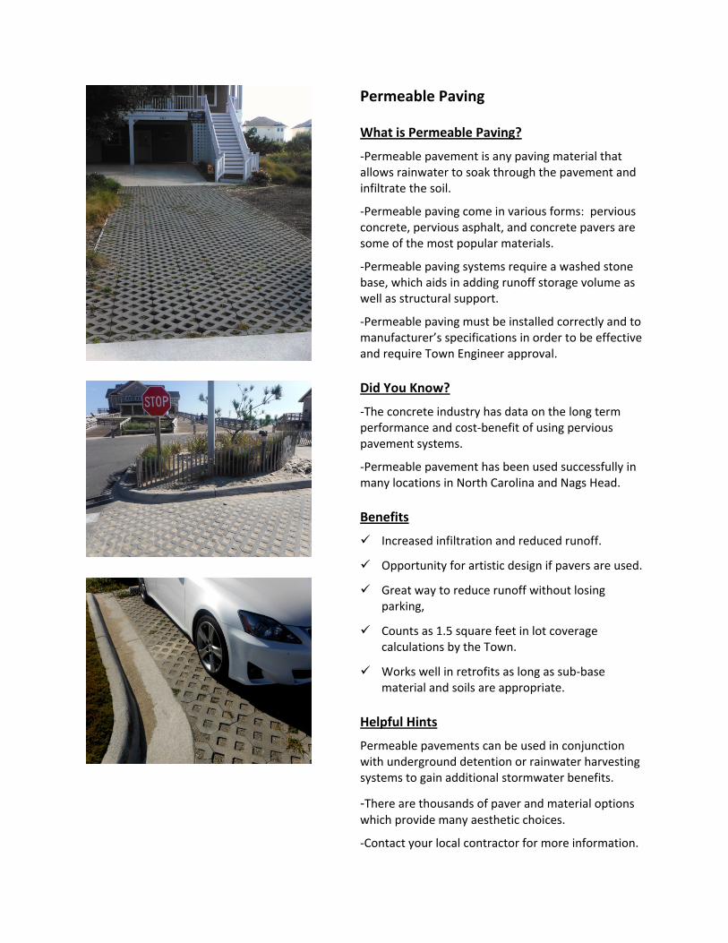
Permeable Paving What is Permeable Paving?
‐Permeable pavement is any paving material that allows rainwater to soak through the pavement and infiltrate the soil.
‐Permeable paving come in various forms: pervious concrete, pervious asphalt, and concrete pavers are some of the most popular materials.
‐Permeable paving systems require a washed stone base, which aids in adding runoff storage volume as well as structural support.
‐Permeable paving must be installed correctly and to manufacturer’s specifications in order to be effective and require Town Engineer approval. Did You Know?
‐The concrete industry has data on the long term performance and cost‐benefit of using pervious pavement systems.
‐Permeable pavement has been used successfully in many locations in North Carolina and Nags Head. Benefits
Increased infiltration and reduced runoff.
Opportunity for artistic design if pavers are used.
Great way to reduce runoff without losing parking,
Counts as 1.5 square feet in lot coverage calculations by the Town.
Works well in retrofits as long as sub‐base material and soils are appropriate.
Helpful Hints
Permeable pavements can be used in conjunction with underground detention or rainwater harvesting systems to gain additional stormwater benefits.
‐There are thousands of paver and material options which provide many aesthetic choices.
‐Contact your local contractor for more information.
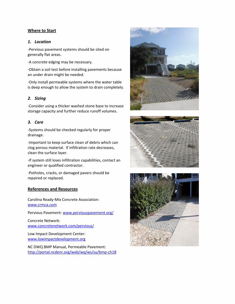
Where to Start 1. Location
‐Pervious pavement systems should be sited on generally flat areas.
‐A concrete edging may be necessary.
‐Obtain a soil test before installing pavements because an under drain might be needed.
‐Only install permeable systems where the water table is deep enough to allow the system to drain completely. 2. Sizing
‐Consider using a thicker washed stone base to increase storage capacity and further reduce runoff volumes. 3. Care
‐Systems should be checked regularly for proper drainage.
‐Important to keep surface clean of debris which can clog porous material. If infiltration rate decreases, clean the surface layer.
‐If system still loses infiltration capabilities, contact an engineer or qualified contractor.
‐Potholes, cracks, or damaged pavers should be repaired or replaced.
References and Resources Carolina Ready‐Mix Concrete Association: www.crmca.com
Pervious Pavement: www.perviouspavement.org/
Concrete Network: www.concretenetwork.com/pervious/
Low Impact Development Center: www.lowimpactdevelopment.org
NC DWQ BMP Manual, Permeable Pavement: http://portal.ncdenr.org/web/wq/ws/su/bmp‐ch18
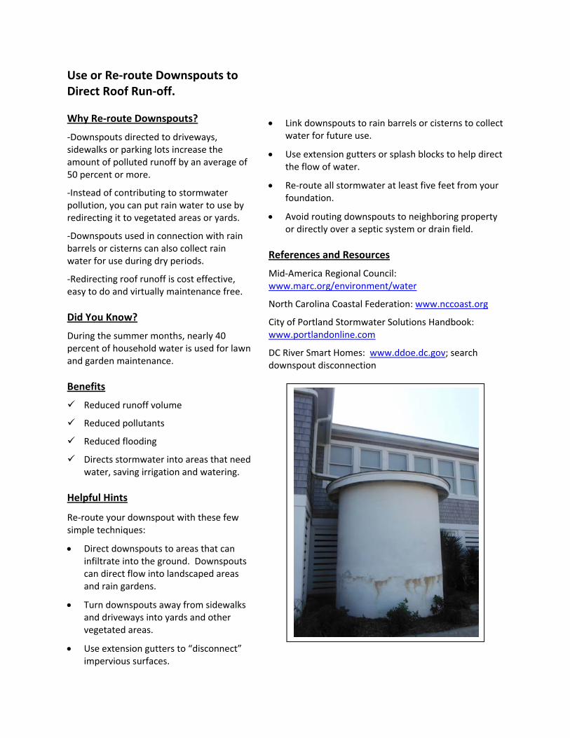
Use or Re‐route Downspouts to Direct Roof Run‐off. Why Re‐route Downspouts?
‐Downspouts directed to driveways, sidewalks or parking lots increase the amount of polluted runoff by an average of 50 percent or more.
‐Instead of contributing to stormwater pollution, you can put rain water to use by redirecting it to vegetated areas or yards.
‐Downspouts used in connection with rain barrels or cisterns can also collect rain water for use during dry periods.
‐Redirecting roof runoff is cost effective, easy to do and virtually maintenance free. Did You Know?
During the summer months, nearly 40 percent of household water is used for lawn and garden maintenance. Benefits
Reduced runoff volume
Reduced pollutants
Reduced flooding
Directs stormwater into areas that need water, saving irrigation and watering.
Helpful Hints
Re‐route your downspout with these few simple techniques:
• Direct downspouts to areas that can infiltrate into the ground. Downspouts can direct flow into landscaped areas and rain gardens.
• Turn downspouts away from sidewalks and driveways into yards and other vegetated areas.
• Use extension gutters to “disconnect” impervious surfaces.
• Link downspouts to rain barrels or cisterns to collect water for future use.
• Use extension gutters or splash blocks to help direct the flow of water.
• Re‐route all stormwater at least five feet from your foundation.
• Avoid routing downspouts to neighboring property or directly over a septic system or drain field.
References and Resources
Mid‐America Regional Council: www.marc.org/environment/water
North Carolina Coastal Federation: www.nccoast.org
City of Portland Stormwater Solutions Handbook: www.portlandonline.com
DC River Smart Homes: www.ddoe.dc.gov; search downspout disconnection
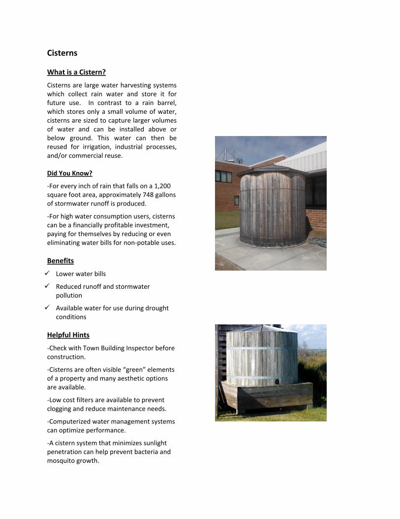
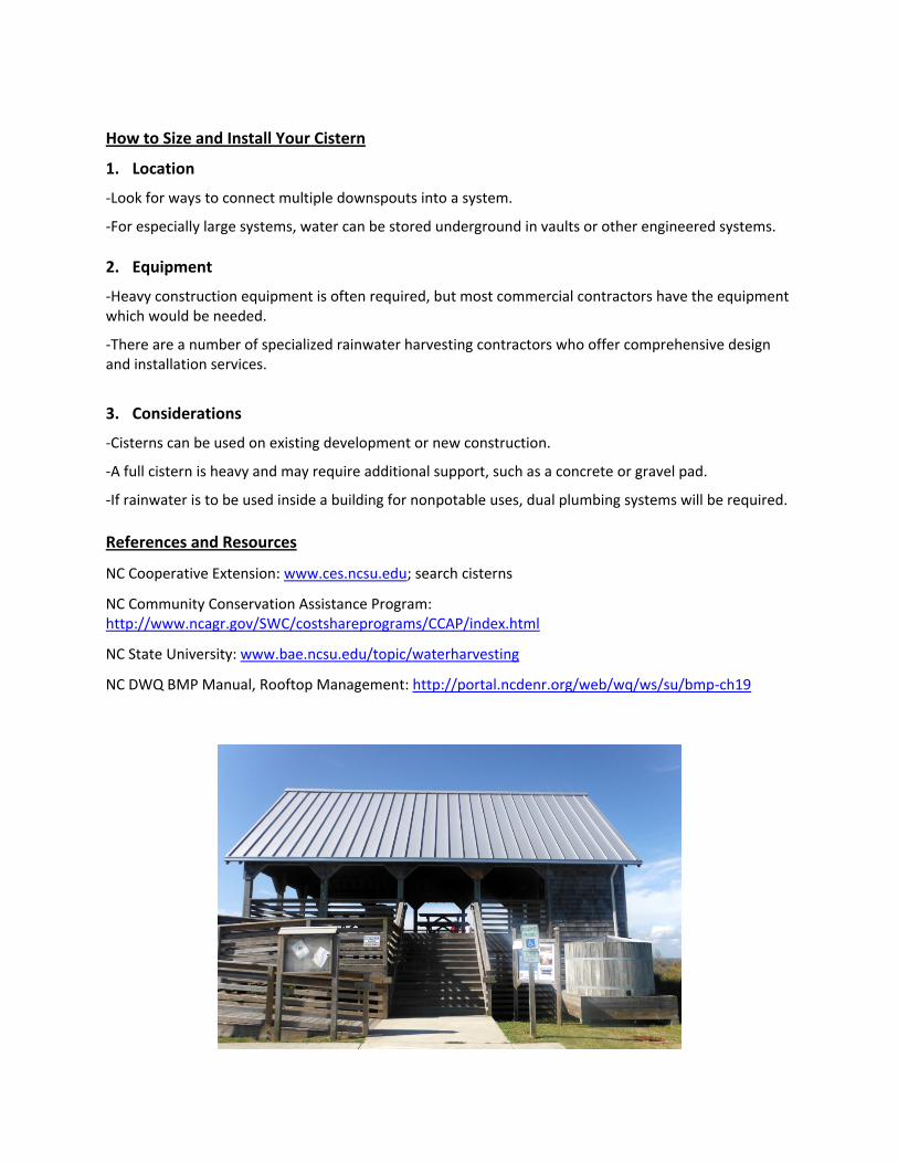
Cisterns What is a Cistern?
Cisterns are large water harvesting systems which collect rain water and store it for future use. In contrast to a rain barrel, which stores only a small volume of water, cisterns are sized to capture larger volumes of water and can be installed above or below ground. This water can then be reused for irrigation, industrial processes, and/or commercial reuse. Did You Know?
‐For every inch of rain that falls on a 1,200 square foot area, approximately 748 gallons of stormwater runoff is produced.
‐For high water consumption users, cisterns can be a financially profitable investment, paying for themselves by reducing or even eliminating water bills for non‐potable uses. Benefits
Lower water bills
Reduced runoff and stormwater pollution
Available water for use during drought conditions
Helpful Hints
‐Check with Town Building Inspector before construction.
‐Cisterns are often visible “green” elements of a property and many aesthetic options are available.
‐Low cost filters are available to prevent clogging and reduce maintenance needs.
‐Computerized water management systems can optimize performance.
‐A cistern system that minimizes sunlight penetration can help prevent bacteria and mosquito growth.
How to Size and Install Your Cistern
1. Location
‐Look for ways to connect multiple downspouts into a system.
‐For especially large systems, water can be stored underground in vaults or other engineered systems. 2. Equipment
‐Heavy construction equipment is often required, but most commercial contractors have the equipment which would be needed.
‐There are a number of specialized rainwater harvesting contractors who offer comprehensive design and installation services.
3. Considerations
‐Cisterns can be used on existing development or new construction.
‐A full cistern is heavy and may require additional support, such as a concrete or gravel pad.
‐If rainwater is to be used inside a building for nonpotable uses, dual plumbing systems will be required.
References and Resources
NC Cooperative Extension: www.ces.ncsu.edu; search cisterns
NC Community Conservation Assistance Program: http://www.ncagr.gov/SWC/costshareprograms/CCAP/index.html
NC State University: www.bae.ncsu.edu/topic/waterharvesting
NC DWQ BMP Manual, Rooftop Management: http://portal.ncdenr.org/web/wq/ws/su/bmp‐ch19
Rain Barrels What is a Rain Barrel?
A rain barrel is a container that collects and stores rainwater from your roof that would otherwise be lost to runoff. Rain barrels come in all shapes and sizes. They typically include the drum, a vinyl hose, PVC couplings and screen to keep debris and insects out. A rain barrel can sit conveniently under any residential gutter downspout. Did you know?
‐One quarter inch (¼”) of rain produces enough runoff to fill a typical rain barrel hooked up to one downspout.
‐If you and your neighbors all added just one rain barrel, it would have a significant impact on flooding and pollution in your community.
‐One 55 gallon rain barrel holds a full week’s worth of water for a 10’x10’ garden.
‐Rain barrels come in a variety of sizes, colors and designs and are available for purchase locally and on‐line. Benefits
Lower water bills
Reduced runoff and stormwater pollution
Available water for watering plants during drought
The natural nutrients of rainwater needed ‐for healthy plants
Helpful hints
‐Always keep the lid to your barrel tightly secured to avoid any accidents involving children or animals.
‐Do not consume water collected in barrel!
How to Size and Install Your Rain Barrel
‐Most rain barrels are easy to install; however, actual installation methods vary depending on the type of rain barrel. Installation typically involves disconnecting your downspout, cutting off a portion of the downspout and redirecting it into the top of the barrel.
‐Most rain barrels have an overflow pipe that redirects the rainwater back into the downspout or onto your lawn or other surface in the event the barrel is full.
‐Some barrels come with safety features, spigots, mosquito proofing, and even water filters.
‐Some barrels come with connection attachments so that multiple barrels can work together. Care
‐Use water between rains, or empty prior to storms.
‐Annually empty and wash out barrel.
‐Clean your gutters regularly to prevent debris.
‐If you see algae, add one cap of chlorine bleach to a full barrel of water; this small amount won’t hurt plants.
References and Resources
NC Cooperative Extension: www.ces.ncsu.edu; search rainwater
NC State University: www.bae.ncsu.edu/topic/; click water harvesting
NC Coastal Federation: www.nccoast.org; click low impact development
Rain Gardens
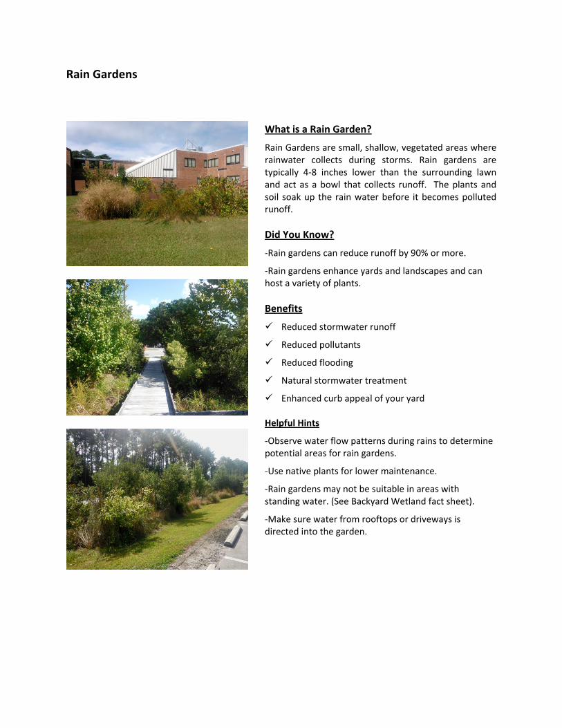
What is a Rain Garden?
Rain Gardens are small, shallow, vegetated areas where rainwater collects during storms. Rain gardens are typically 4‐8 inches lower than the surrounding lawn and act as a bowl that collects runoff. The plants and soil soak up the rain water before it becomes polluted runoff. Did You Know?
‐Rain gardens can reduce runoff by 90% or more.
‐Rain gardens enhance yards and landscapes and can host a variety of plants. Benefits
Reduced stormwater runoff
Reduced pollutants
Reduced flooding
Natural stormwater treatment
Enhanced curb appeal of your yard Helpful Hints
‐Observe water flow patterns during rains to determine potential areas for rain gardens.
‐Use native plants for lower maintenance.
‐Rain gardens may not be suitable in areas with standing water. (See Backyard Wetland fact sheet).
‐Make sure water from rooftops or driveways is directed into the garden.

Build and Plant 1. Location
‐Select an area to capture and absorb runoff based on how water flows across your land.
‐Site the garden at least 10’ from you house, and 25’ from wells or septic fields.
‐Make sure the soil will drain.
‐Plant flowers, shrubs, grasses or even turf. 2. Equipment
‐A small rain garden can be built by hand in a weekend, but, contact Town staff or a local contractor for additional assistance if needed. 3. Planting
‐Heavy double or triple shredded hardwood mulch works best because it won’t float away. It also helps retain moisture for the plants.
‐Choose native vegetation when possible. 4. Care
‐Periodically water garden until established.
‐Mulch annually. References and Resources
See the “Native Landscaping and Tree Planting” fact sheet for more help, or contact your local nursery or Dare County Cooperative Extension for more assistance.
NC State University Rain Garden Guide: www.bae.ncsu.edu; search rain gardens
NC Cooperative Extension: http://www.darenc.com/soilwater/raingrdn.asp
NC Coastal Federation: www.nccoast.org; search low impact development
Backyard Wetlands
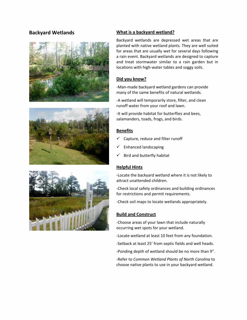
What is a backyard wetland?
Backyard wetlands are depressed wet areas that are planted with native wetland plants. They are well suited for areas that are usually wet for several days following a rain event. Backyard wetlands are designed to capture and treat stormwater similar to a rain garden but in locations with high‐water tables and soggy soils. Did you know?
‐Man‐made backyard wetland gardens can provide many of the same benefits of natural wetlands.
‐A wetland will temporarily store, filter, and clean runoff water from your roof and lawn.
‐It will provide habitat for butterflies and bees, salamanders, toads, frogs, and birds. Benefits
Capture, reduce and filter runoff
Enhanced landscaping
Bird and butterfly habitat Helpful Hints
‐Locate the backyard wetland where it is not likely to attract unattended children.
‐Check local safety ordinances and building ordinances for restrictions and permit requirements.
‐Check soil maps to locate wetlands appropriately. Build and Construct
‐Choose areas of your lawn that include naturally occurring wet spots for your wetland.
‐Locate wetland at least 10 feet from any foundation.
‐Setback at least 25’ from septic fields and well heads.
‐Ponding depth of wetland should be no more than 9”.
‐Refer to Common Wetland Plants of North Carolina to choose native plants to use in your backyard wetland.
References and Resources
Natural Resources Conservation Service: https://prod.nrcs.usda.gov/wps/portal/nrcs/detail/national/newsroom/features/?cid=nrcs143_023525
NCSU Urban Waterways – Designing Stormwater Wetlands for Small Watersheds:
http://www.bae.ncsu.edu/stormwater/PublicationFiles/SWwetlands2000.pdf
Common Wetland Plants of North Carolina, produced by the N.C. Department of Environment and Natural Resources, Division of Water Quality:
http://portal.ncdenr.org/c/document_library/get_file?uuid=d0f7bb32‐5585‐4acf‐a399‐8d484488d234&groupId=38364
Division of Soil and Water Conservation Community Conservation Assistance Program: http://www.ncagr.gov/SWC/costshareprograms/CCAP/index.html
French Drains
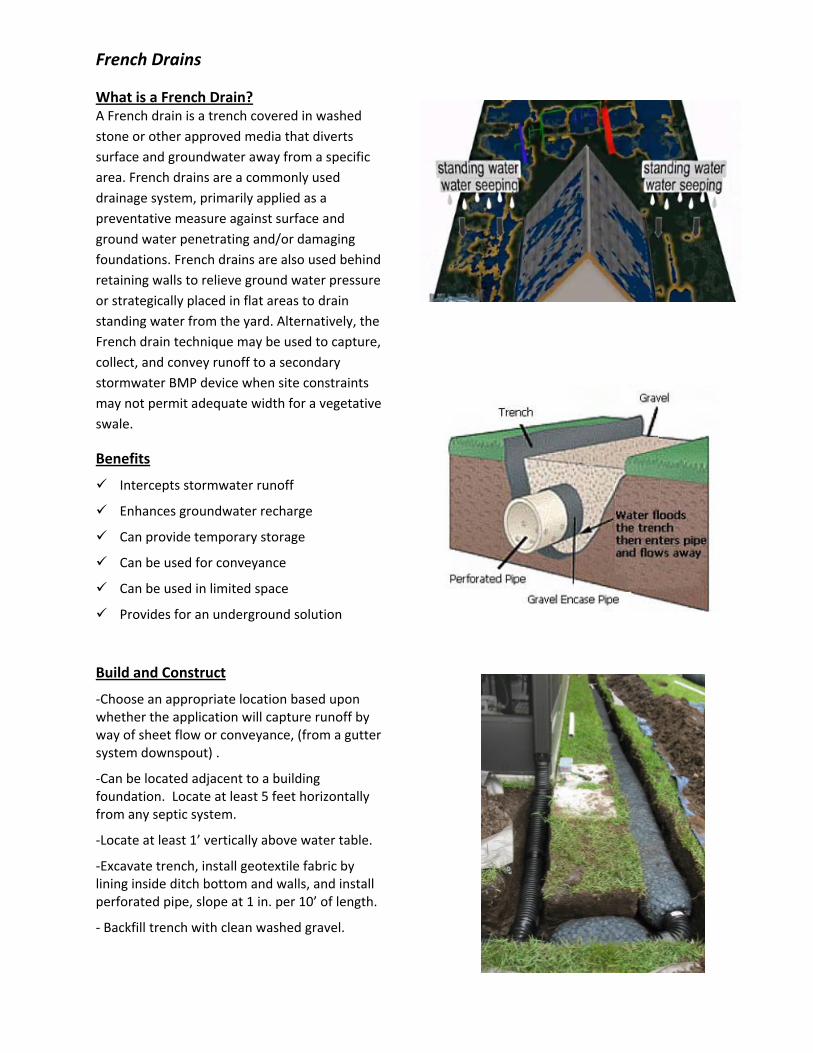
What is a French Drain? A French drain is a trench covered in washed stone or other approved media that diverts surface and groundwater away from a specific area. French drains are a commonly used drainage system, primarily applied as a preventative measure against surface and ground water penetrating and/or damaging foundations. French drains are also used behind retaining walls to relieve ground water pressure or strategically placed in flat areas to drain standing water from the yard. Alternatively, the French drain technique may be used to capture, collect, and convey runoff to a secondary stormwater BMP device when site constraints may not permit adequate width for a vegetative swale.
Benefits
Intercepts stormwater runoff
Enhances groundwater recharge
Can provide temporary storage
Can be used for conveyance
Can be used in limited space
Provides for an underground solution
Build and Construct
‐Choose an appropriate location based upon whether the application will capture runoff by way of sheet flow or conveyance, (from a gutter system downspout) .
‐Can be located adjacent to a building foundation. Locate at least 5 feet horizontally from any septic system.
‐Locate at least 1’ vertically above water table.
‐Excavate trench, install geotextile fabric by lining inside ditch bottom and walls, and install perforated pipe, slope at 1 in. per 10’ of length.
‐ Backfill trench with clean washed gravel.
Native Landscaping and Tree Planting
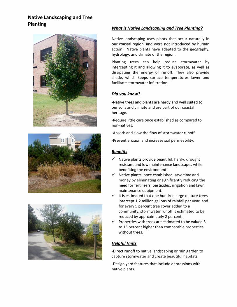
What is Native Landscaping and Tree Planting?
Native landscaping uses plants that occur naturally in our coastal region, and were not introduced by human action. Native plants have adapted to the geography, hydrology, and climate of the region.
Planting trees can help reduce stormwater by intercepting it and allowing it to evaporate, as well as dissipating the energy of runoff. They also provide shade, which keeps surface temperatures lower and facilitate stormwater infiltration. Did you know?
‐Native trees and plants are hardy and well suited to our soils and climate and are part of our coastal heritage.
‐Require little care once established as compared to non‐natives.
‐Absorb and slow the flow of stormwater runoff.
‐Prevent erosion and increase soil permeability. Benefits
Native plants provide beautiful, hardy, drought resistant and low maintenance landscapes while benefiting the environment.
Native plants, once established, save time and money by eliminating or significantly reducing the need for fertilizers, pesticides, irrigation and lawn maintenance equipment.
It is estimated that one hundred large mature trees intercept 1.2 million gallons of rainfall per year, and for every 5 percent tree cover added to a community, stormwater runoff is estimated to be reduced by approximately 2 percent.
Properties with trees are estimated to be valued 5 to 15 percent higher than comparable properties without trees.
Helpful Hints
‐Direct runoff to native landscaping or rain garden to capture stormwater and create beautiful habitats.
‐Design yard features that include depressions with native plants.

Build and Plant
Use the landscape to help keep rain water on site.
Plant trees that maximize interception of rain.
Plant native trees with higher growth rates. References and Resources
www.ncsu.edu/goingnative/howto/index.html
NC Coastal Federation: www.nccoast.org; search native plants
Water Forestry Guide: www.forestsforwatershed.org
Local Nurseries and Landscape Professionals
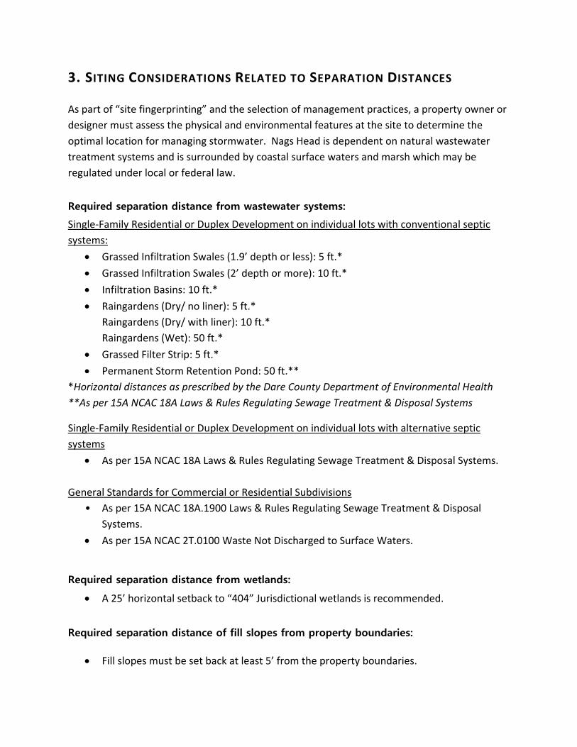
3. SITING CONSIDERATIONS RELATED TO SEPARATION DISTANCES As part of “site fingerprinting” and the selection of management practices, a property owner or designer must assess the physical and environmental features at the site to determine the optimal location for managing stormwater. Nags Head is dependent on natural wastewater treatment systems and is surrounded by coastal surface waters and marsh which may be regulated under local or federal law. Required separation distance from wastewater systems:
Single‐Family Residential or Duplex Development on individual lots with conventional septic systems:
• Grassed Infiltration Swales (1.9’ depth or less): 5 ft.* • Grassed Infiltration Swales (2’ depth or more): 10 ft.* • Infiltration Basins: 10 ft.* • Raingardens (Dry/ no liner): 5 ft.*
Raingardens (Dry/ with liner): 10 ft.* Raingardens (Wet): 50 ft.*
• Grassed Filter Strip: 5 ft.* • Permanent Storm Retention Pond: 50 ft.**
*Horizontal distances as prescribed by the Dare County Department of Environmental Health **As per 15A NCAC 18A Laws & Rules Regulating Sewage Treatment & Disposal Systems
Single‐Family Residential or Duplex Development on individual lots with alternative septic systems
• As per 15A NCAC 18A Laws & Rules Regulating Sewage Treatment & Disposal Systems.
General Standards for Commercial or Residential Subdivisions • As per 15A NCAC 18A.1900 Laws & Rules Regulating Sewage Treatment & Disposal
Systems. • As per 15A NCAC 2T.0100 Waste Not Discharged to Surface Waters.
Required separation distance from wetlands:
• A 25’ horizontal setback to “404” Jurisdictional wetlands is recommended.
Required separation distance of fill slopes from property boundaries:
• Fill slopes must be set back at least 5’ from the property boundaries.
4. USING LID TO COMPLY WITH TOWN REQUIREMENTS When is a stormwater plan required by the Town of Nags Head?
The requirements to retain and treat stormwater on site are described in Chapter 34 of the Town’s Code of Ordinances.
A stormwater plan is not required for residential development that does not use fill, lot disturbance limited to site investigations (for the purpose of surveying or determining septic suitability), and land disturbance and fill used in the repair and/or replacement of existing septic systems.
A stormwater plan is required as part of an application for commercial and multi‐family development and redevelopment and for residential development that uses fill. If your project is a single‐family or duplex residential lot using fill, note that there are two tiers of stormwater planning:
1. Residential NON‐ENGINEERED Plans for fill amounts of 2' or less. 2. Residential ENGINEERED Plans for fill amounts of greater than 2'.
Who can develop a stormwater plan?
For a stormwater plan for a commercial, mixed‐use or multi‐lot development such as a subdivision, a designer shall be a qualified and registered design professional knowledgeable within the field of work for the performance of the design, construction, and operation and maintenance of what is being proposed. This could include someone qualified in engineering, landscape architecture, architecture or environmental design. Stormwater plans that include engineering, or those plans that utilized a height of fill greater than 2 feet from the existing or natural grade, must be sealed by a Practicing Engineer and will be reviewed by the Town Engineer.
For a stormwater plan for a single‐family residential application where proposed fill amounts do not exceed 2’ in height from the pre‐development surface grades, than the design may be submitted by anyone, including those who are not registered design professionals or engineers, as long as the plan follows the guidelines for management practices provided in this manual. The goal is to allow smaller scale projects to be developed with minimal up‐front costs through the implementation of LID approaches outlined in this Manual. So for example, the design of Swales must follow the specifications laid out in Table A. The design of rain gardens must follow the specifications of Table B. Stormwater Plans developed under this approached will be reviewed by Town staff certified in LID.
Stormwater plans submitted are not required to implement only the methods described within this manual; however, the methods, calculations, tables, figures, and procedures outlined in this manual as well as the NC BMP Manual will be used to review and issue decisions concerning proposed BMP’s for compliance with Sections 34‐5 through 35‐7 of the Code of Ordinances, and alternative designs will need to show reasoning behind proposals and to indicate equal or better performance for the BMP’s included in this Manual.
What are the steps to developing an effective stormwater plan under the Town Ordinance?
1. Conduct a site evaluation or “site fingerprinting.” Evaluate your site’s drainages, soils, existing vegetation, topography, elevation and slope, as well as its proximity to areas of environmental concern or AEC’s. Identify any areas that can be left undisturbed or that may be incorporated into the stormwater plan you develop.
2. Evaluate lot coverage allowance and setback requirements for the use you are proposing and the Zoning District you are in. Identify opportunities for minimizing impervious coverage, such as the use of porous materials, or opportunities for shared driveways or parking. Note that use of fill requires information on existing and proposed elevations and that fill slopes must be set back at least 5’ from the property boundaries.
3. Determine the volume of stormwater you must capture and treat on the lot. This will be the amount of runoff generated by all the pervious or partially pervious surfaces in the development at a volume of 4.3” for commercial applications, and 1.5” for residential applications.
4. Identify and locate those BMP’s within the site that can work together to meet
requirements. Develop a plan schematic that will be incorporated into application survey (and included in as‐built survey at the end of the project).
5. Submit an application that includes:
All forms and documentation that is pertinent to your project and site. This could include the development and redevelopment permit application, floodplain permit application, CAMA and/or Septic Health permits.
If submittal requires State permits for stormwater or sedimentation and erosion control or other State permits, please provide documentation on those as part of your application to the Town.
Provide a survey drawing that shows all existing and proposed elements, and elevations.
6. Ask for help if you need it!

Town of Nags Head Application Requirements Chapter 34 Stormwater, Fill, & Runoff Management of the Town of Nags Head Code of Ordinances, sets forth the requirements for stormwater management in the Town. If you are required to submit a stormwater management plan as part of your development or redevelopment project, than you must complete the application requirements. All application forms are available at the Planning and Development Department in Town Hall or on the Town website. This includes:
1. A Land Disturbance Permit Application (part of the Town Development Application Form). This application may trigger additional permitting requirements for a Floodplain Permit, and Sedimentation and Erosion Control, or a State stormwater permit or local stormwater management plan.
2. A stormwater management plan (with accompanying supporting calculations and data, as appropriate)
3. A stormwater management maintenance agreement 4. A nonrefundable stormwater management permit application review fee which is the same as a
zoning review fee. 5. Other permits pertaining to the project such as CAMA or the State Department of Health.
Application Procedure
1. Permit applications shall be submitted to the Town of Nags Head Monday‐Friday from 8:30am to 5:00pm, and must be complete prior to staff review.
2. One printed copy of all documents shall be submitted. 3. One electronic copy of all documents shall be submitted in a Portable Document Format (PDF).
This may be emailed or submitted on appropriate media (compact disc, digital video disc, USB flash drive, other, as deemed appropriate by the Town.
4. If any component of the stormwater plan or other permit application materials are insufficient, the applicant may revise and resubmit the disapproved component without revising and resubmitting other components except as deemed necessary by the Town. No additional fee is required for the resubmittal.
5. The stormwater management permit shall be issued upon approval of all stormwater management application components.
Permit Duration Stormwater Management plans shall be valid for the duration of the Development / Redevelopment or land disturbance permit from the Town. This means from the date of issuance through the date the Town notifies the permit holder that all stormwater management measures have passed the final inspection required under the permit conditions. An approved land disturbance permit expires if work does not commence within six months of the date of issuance, if work is discontinued for a period of more than one year, or upon the expiration or completion of a building permit.

Stormwater Management Plan Minimum Requirements The Stormwater Management plan shall include sufficient information to evaluate the characteristics of the project site; the potential impacts of all proposed construction on water resources; and the effectiveness and acceptability of the measures proposed for managing stormwater at the project site (See “Stormwater Plan Elements”). The stormwater management plan may be incorporated into other design/construction plan documents associated with a building permit or those for roadways, sanitary sewer collection, potable water supply, erosion/sedimentation control, landscaping, and others, depending on the project.
Applicability 1. For residential or duplex lots that require an engineered stormwater management plan, the plan
shall be submitted with the Land Disturbance Permit application, and shall be reviewed by the Town Engineer for approval.
2. For residential or duplex lots that do not require an engineered stormwater management plan, the plan shall be submitted as part of the application for a building permit and shall be reviewed by the Planning Director or his/her designees.
3. For all subdivisions and commercial applications, a stormwater management plan with all supporting documentation meeting all Town requirements and standards shall be submitted with the plat or site plan application for approval by the Town Engineer. For projects that require stormwater permits from the State, a copy of the stormwater management plan shall be submitted for the permit record.
4. For conditional uses, a preliminary stormwater management plan shall be submitted with the Conditional Use Permit application. A stormwater management plan with all supporting documentation meeting all Town requirements and standards shall be submitted with, or in advance of, the application for a building permit.
Note:
• Conditional Uses and Major Subdivisions are also reviewed by the Town’s Planning Board and Board of Commissioners.
• Zoning and building permit requirements will be addressed as part of this process. Plan Information Supporting plans and documentation including assumptions, methodology, calculations and conclusions shall be submitted to the Town. The stormwater management plan shall include engineered and non‐engineered drawings, maps, assumptions, calculations and narrative statements, including:

1. General Information: The name and physical address of the project; The name, address, telephone number of all entities having a legal interest in the property; Associated legal references (deed, plat, etc); Parcel Identification Number(s) (PINs) of the project; and a vicinity map indicating project location, adjacent roads, and the nearest public road intersection.
2. Existing Conditions: Sheets or maps indicating existing features, including buildings, ground surface elevations, landforms, parking areas, roadways, structures, subsurface utilities, surface utilities, surface waters, watercourses, vegetation, and other significant elements. Ground elevation contours shall be depicted at 1’ intervals with spot elevations depicting depressions and peaks. Contours shall extend 15’ beyond property boundaries to the extent practicable.
3. Project Boundaries clearly depicted and labeled, including any staging areas.
4. Locations and Elevations of adjoining street pavement, shoulder, ditches, and drainage systems, as well as upstream and downstream driveway culverts.
5. Dare County Health Department septic permit and site evaluation of approximate elevation of seasonal high water table or the “seasonal high wetness condition,” and any fill requirements for determining vertical separation compliance of BMPs.
6. Lateral & Vertical Separation Distances from Areas of Environmental Concern, State surface waters, subsurface water conditions, above ground and underground utilities, or other separation distances as required by existing federal, state or local laws clearly depicted.
7. Proposed Conditions: Sheets or maps indicating location of proposed features including buildings and other Built Upon Area (“BUA”), ground surface elevations, landforms, parking areas, roadways, structures, subsurface utilities, landscaping, and other significant elements.
8. Proposed Elevation Contours depicted at 1.0’ intervals describing the proposed elements with spot elevations depicted in areas of proposed fill and Finished Floor elevations for all proposed buildings/structures described. Notational information shall be provided which includes existing surface elevation at each site element, proposed maximum fill depths for each site element, and maximum fill depth within the project site.
9. Location and Description of Proposed Stormwater BMP’s to capture runoff from all surfaces within a given drainage area.
10. Design Details: Plan sheets or drawings indicating construction/installation methods sufficient to construct/install all components in conjunction with proposed conditions sheets/maps.
11. A Written Narrative describing existing conditions, proposed conditions, proposed BMP’s, drainage
area(s), and any other analysis or methods employed that will assist in the review of the application.
Built Upon Area
Built‐upon Area (BUA) or Impervious Coverage is that portion of a development project that is covered by impervious materials or partially impervious surfaces and is used to calculate stormwater run‐off potential, including buildings; pavement and compacted gravel areas such as roads or parking lots, and paths and recreation facilities such as athletic courts and concrete pool decks. BUA does not include the surface area of pools, wooden slatted decks, or un‐compacted, washed gravel, or pervious or partially pervious paving material to the extent that the paving material absorbs water or allows water to infiltrate through the paving material. The Town of Nags Head also has zoning regulations concerning the total amount of lot coverage which apply related to zoning districts and use. Lot coverage is a distinct calculation from BUA, and includes pools, decks and other usage of the property. All built‐upon area counts toward lot coverage within zoning review, however, not all lot coverage is considered built upon area for calculating stormwater runoff.
Construction Record
Once project is built, the construction record or as‐built plans or surveys shall include on‐site stormwater management measures. These plans shall be prepared by a licensed surveyor and shall include all of the elements shown as proposed on the approved construction plans and depict sufficient topographic information to demonstrate compliance. These shall be submitted to the Town prior to the issuance of a Certificate of Compliance.
Certification
Upon completion of construction, stormwater management facilities shall be certified by a qualified and authorized professional as having been constructed in substantial conformity with the Town‐approved plans and specifications. The acceptability of a certification by any other person than the person who prepared the original design shall be at the sole discretion of the Town. A copy of this documentation shall be submitted to the Town prior to the issuance of a Certificate of Compliance.
Operations and Maintenance Agreement
An LID approach to on‐site stormwater management is a comprehensive approach that has built‐in redundancy, reducing the possibility of failure. Many LID techniques can perform effectively with little to no maintenance. However, others require oversight.
• Rain‐barrels and cisterns are only effective when the stormwater collected is regularly used or periodically drained out.
• Porous pavements, geo‐webbing or blocks such as Turfstone must be kept free of debris that can clog the surface material and prevent the infiltration.

• Particular BMP technologies such as engineered collection boxes, or weirs and dams associated with stormwater ponds, usually come with specifications for maintenance from the installer or the manufacturer.
• Landscape‐based practices should be kept free of trash and invasive plants.
Therefore, an Operations and Maintenance Agreement will be required for the Certificate of Compliance for all Stormwater Plans. This agreement is filed with the Town along with the as‐builts of a project so that there is a record of BMP functional requirements in case something may fail in the future. Maintenance Agreements will indicate party/parties responsible for maintenance and operation and record keeping, long term funding for maintenance if needed, how Operation and Maintenance will be transferred along with the property and any specifications or maintenance needs for the particular BMP’s used as part of the Plan.
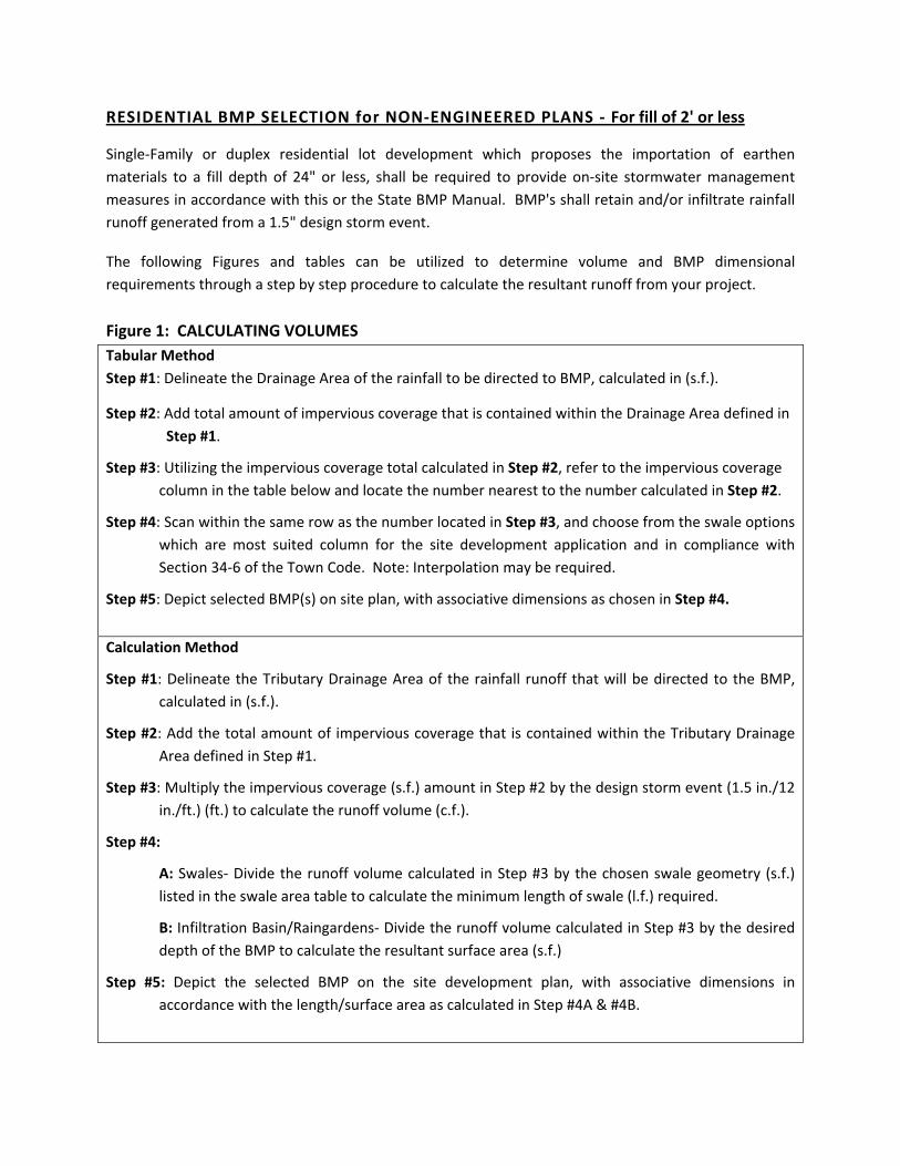
RESIDENTIAL BMP SELECTION for NON‐ENGINEERED PLANS ‐ For fill of 2' or less
Single‐Family or duplex residential lot development which proposes the importation of earthen materials to a fill depth of 24" or less, shall be required to provide on‐site stormwater management measures in accordance with this or the State BMP Manual. BMP's shall retain and/or infiltrate rainfall runoff generated from a 1.5" design storm event.
The following Figures and tables can be utilized to determine volume and BMP dimensional requirements through a step by step procedure to calculate the resultant runoff from your project. Figure 1: CALCULATING VOLUMES Tabular Method Step #1: Delineate the Drainage Area of the rainfall to be directed to BMP, calculated in (s.f.).
Step #2: Add total amount of impervious coverage that is contained within the Drainage Area defined in Step #1.
Step #3: Utilizing the impervious coverage total calculated in Step #2, refer to the impervious coverage column in the table below and locate the number nearest to the number calculated in Step #2.
Step #4: Scan within the same row as the number located in Step #3, and choose from the swale options which are most suited column for the site development application and in compliance with Section 34‐6 of the Town Code. Note: Interpolation may be required.
Step #5: Depict selected BMP(s) on site plan, with associative dimensions as chosen in Step #4. Calculation Method
Step #1: Delineate the Tributary Drainage Area of the rainfall runoff that will be directed to the BMP, calculated in (s.f.).
Step #2: Add the total amount of impervious coverage that is contained within the Tributary Drainage Area defined in Step #1.
Step #3: Multiply the impervious coverage (s.f.) amount in Step #2 by the design storm event (1.5 in./12 in./ft.) (ft.) to calculate the runoff volume (c.f.).
Step #4:
A: Swales‐ Divide the runoff volume calculated in Step #3 by the chosen swale geometry (s.f.) listed in the swale area table to calculate the minimum length of swale (l.f.) required.
B: Infiltration Basin/Raingardens‐ Divide the runoff volume calculated in Step #3 by the desired depth of the BMP to calculate the resultant surface area (s.f.)
Step #5: Depict the selected BMP on the site development plan, with associative dimensions in accordance with the length/surface area as calculated in Step #4A & #4B.
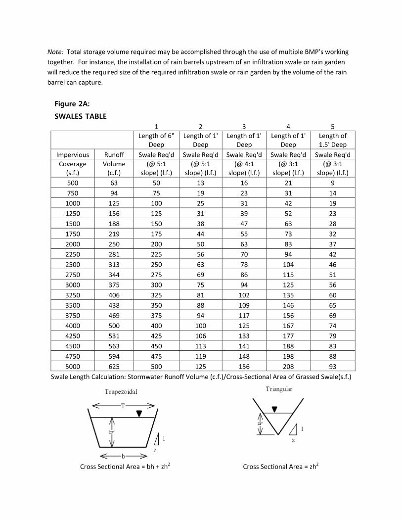
Note: Total storage volume required may be accomplished through the use of multiple BMP’s working together. For instance, the installation of rain barrels upstream of an infiltration swale or rain garden will reduce the required size of the required infiltration swale or rain garden by the volume of the rain barrel can capture. Figure 2A:
SWALES TABLE 1 2 3 4 5
Length of 6"
Deep Length of 1'
Deep Length of 1'
Deep Length of 1'
Deep Length of 1.5' Deep
Impervious Runoff Swale Req'd Swale Req'd Swale Req'd Swale Req'd Swale Req'd Coverage (s.f.)
Volume (c.f.)
(@ 5:1 slope) (l.f.)
(@ 5:1 slope) (l.f.)
(@ 4:1 slope) (l.f.)
(@ 3:1 slope) (l.f.)
(@ 3:1 slope) (l.f.)
500 63 50 13 16 21 9 750 94 75 19 23 31 14 1000 125 100 25 31 42 19 1250 156 125 31 39 52 23 1500 188 150 38 47 63 28 1750 219 175 44 55 73 32 2000 250 200 50 63 83 37 2250 281 225 56 70 94 42 2500 313 250 63 78 104 46 2750 344 275 69 86 115 51 3000 375 300 75 94 125 56 3250 406 325 81 102 135 60 3500 438 350 88 109 146 65 3750 469 375 94 117 156 69 4000 500 400 100 125 167 74 4250 531 425 106 133 177 79 4500 563 450 113 141 188 83 4750 594 475 119 148 198 88 5000 625 500 125 156 208 93
Swale Length Calculation: Stormwater Runoff Volume (c.f.)/Cross‐Sectional Area of Grassed Swale(s.f.)
Cross Sectional Area = bh + zh2
Cross Sectional Area = zh2
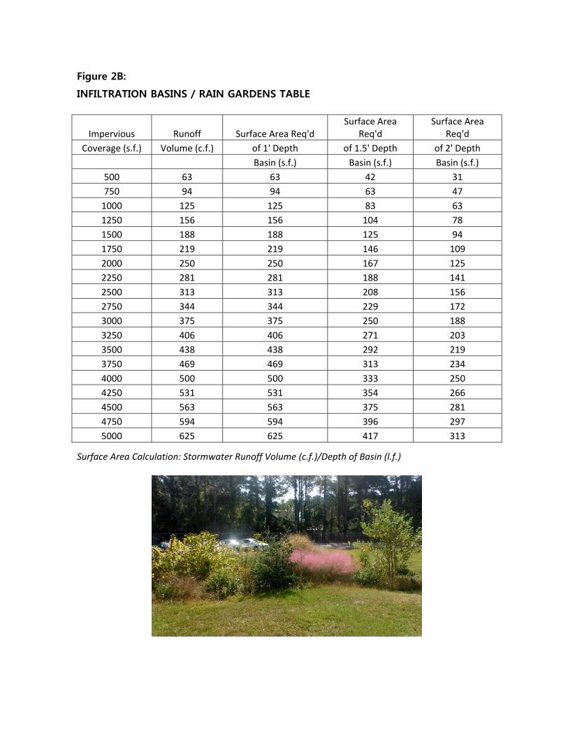
Figure 2B:
INFILTRATION BASINS / RAIN GARDENS TABLE
Impervious Runoff Surface Area Req'd Surface Area
Req'd Surface Area
Req'd Coverage (s.f.) Volume (c.f.) of 1' Depth of 1.5' Depth of 2' Depth
Basin (s.f.) Basin (s.f.) Basin (s.f.) 500 63 63 42 31 750 94 94 63 47 1000 125 125 83 63 1250 156 156 104 78 1500 188 188 125 94 1750 219 219 146 109 2000 250 250 167 125 2250 281 281 188 141 2500 313 313 208 156 2750 344 344 229 172 3000 375 375 250 188 3250 406 406 271 203 3500 438 438 292 219 3750 469 469 313 234 4000 500 500 333 250 4250 531 531 354 266 4500 563 563 375 281 4750 594 594 396 297 5000 625 625 417 313
Surface Area Calculation: Stormwater Runoff Volume (c.f.)/Depth of Basin (l.f.)
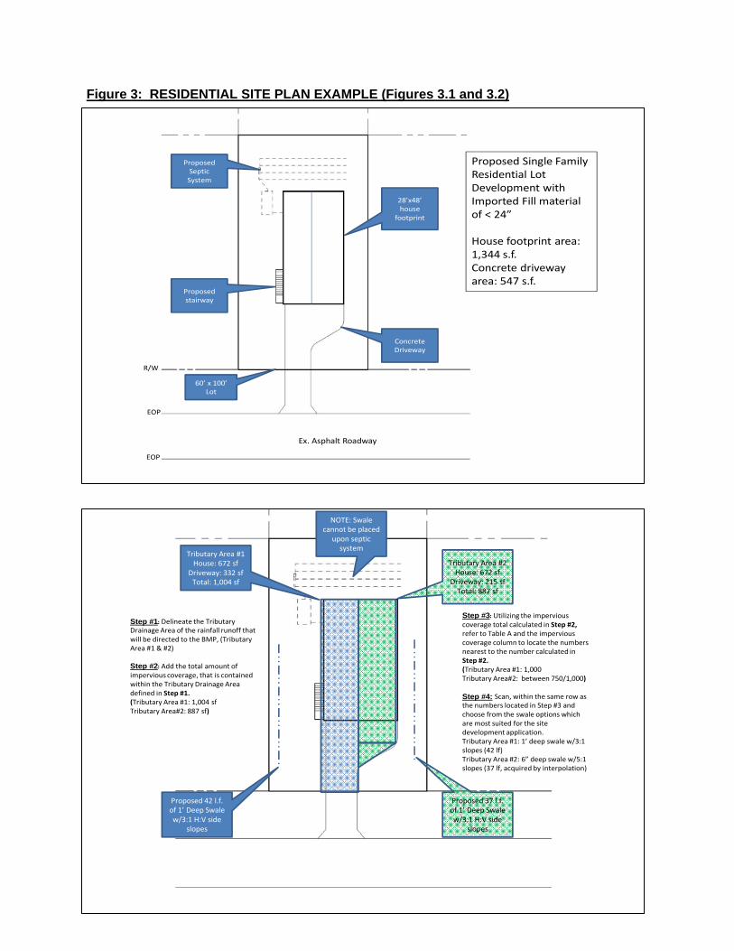
Figure 3: RESIDENTIAL SITE PLAN EXAMPLE (Figures 3.1 and 3.2)
28’x48’ house
footprint
Proposed stairway
Proposed Septic System
Concrete Driveway
60’ x 100’ Lot
R/W
Ex. Asphalt Roadway
EOP
EOP
Proposed Single Family Residential Lot Development with Imported Fill material of < 24”
House footprint area: 1,344 s.f.Concrete driveway area: 547 s.f.
Tributary Area #1House: 672 sf
Driveway: 332 sfTotal: 1,004 sf
Tributary Area #2House: 672 sf
Driveway: 215 sfTotal: 887 sf
Proposed 42 l.f. of 1’ Deep Swale w/3:1 H:V side
slopes
Proposed 37 l.f. of 1’ Deep Swale w/3:1 H:V side
slopes
NOTE: Swale cannot be placed
upon septic system
Step #1: Delineate the Tributary Drainage Area of the rainfall runoff that will be directed to the BMP, (Tributary Area #1 & #2)
Step #2: Add the total amount of impervious coverage, that is contained within the Tributary Drainage Area defined in Step #1.(Tributary Area #1: 1,004 sfTributary Area#2: 887 sf)
Step #3: Utilizing the impervious coverage total calculated in Step #2, refer to Table A and the impervious coverage column to locate the numbers nearest to the number calculated in Step #2.(Tributary Area #1: 1,000Tributary Area#2: between 750/1,000)
Step #4: Scan, within the same row as the numbers located in Step #3 and choose from the swale options which are most suited for the site development application.Tributary Area #1: 1’ deep swale w/3:1 slopes (42 lf)Tributary Area #2: 6” deep swale w/5:1 slopes (37 lf, acquired by interpolation)

RESIDENTIAL BMP SELECTION for ENGINEERED PLANS ‐ For fill amounts of greater than 2'
Single‐Family or duplex residential lot development which proposes the importation of earthen materials of a fill depth of greater than 24", are required to provide on‐site stormwater management measures, and BMP's are required to retain and/or infiltrate rainfall runoff generated from a 2.15" design storm event and must be designed and certified by a Professional Engineer. Design of these systems shall comply with the NCDENR Stormwater Best Management Practices Manual.
COMMERCIAL/MULTI‐FAMILY BMP SELECTION for ENGINEERED Plans – For all Commercial and Multi‐family residential projects. Commercial & multi‐family development projects are required to drain all new built‐upon area into an approved stormwater management system designed to accommodate the volume of runoff generated by a 4.3” design storm. Stormwater Management Plans must be prepared by a Professional Engineer and design of these systems shall comply with the NCDENR Stormwater Best Management Practices Manual. It is expected that most commercial and multi‐family projects will require state permitting. In those cases, copies of approved Stormwater Plans filed with the State will meet Town Requirements. Additionally, copies of Operations and Maintenance Agreement Documentation should also be provided to the Town. For Engineered Plans – both residential and commercial/multi‐family, the method to calculate run‐off volume to determine minimum storage volumes for BMP's is a simplified Rational Method approach. The equation is given as follows:
Q = C * I * A Q = Estimated Design Discharge (cfs) C = Composite or Weighted Runoff Coefficient (unitless) I = Rainfall Intensity (in/hr)* A = Watershed area (ac.) *Rainfall Intensity: for Single‐Family Residential Development is 2.15 in/hr for a 1‐hr duration (d): for Commercial/Multi‐Family Development is 2.15 in/hr for a 2‐hr duration (d) Other Acceptable Methods can also be used:
ˉSimple Method (Schueler, 1987) ˉSCS Curve Number Method (NRCS, 1986) ‐Proposed method as approved by Town Engineer for that project
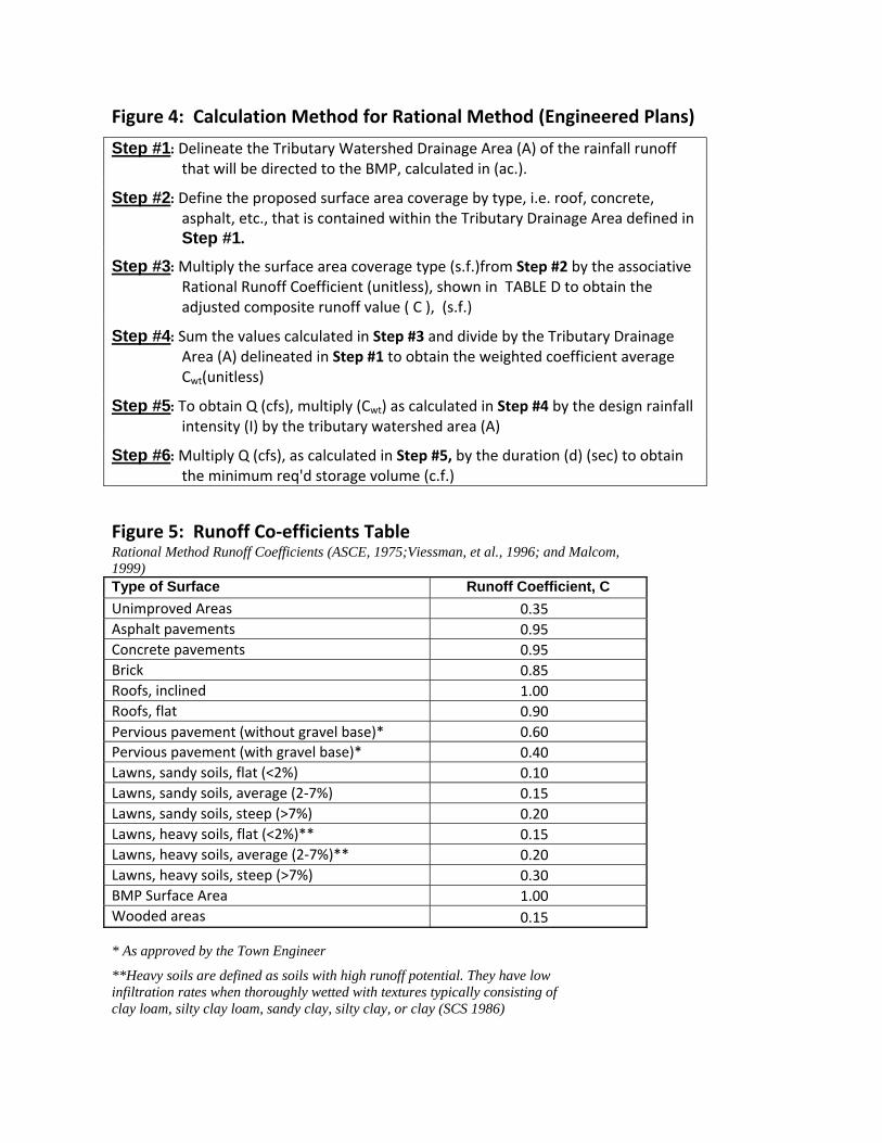
Figure 4: Calculation Method for Rational Method (Engineered Plans) Step #1: Delineate the Tributary Watershed Drainage Area (A) of the rainfall runoff
that will be directed to the BMP, calculated in (ac.).
Step #2: Define the proposed surface area coverage by type, i.e. roof, concrete, asphalt, etc., that is contained within the Tributary Drainage Area defined in Step #1.
Step #3: Multiply the surface area coverage type (s.f.)from Step #2 by the associative Rational Runoff Coefficient (unitless), shown in TABLE D to obtain the adjusted composite runoff value ( C ), (s.f.)
Step #4: Sum the values calculated in Step #3 and divide by the Tributary Drainage Area (A) delineated in Step #1 to obtain the weighted coefficient average Cwt(unitless)
Step #5: To obtain Q (cfs), multiply (Cwt) as calculated in Step #4 by the design rainfall intensity (I) by the tributary watershed area (A)
Step #6: Multiply Q (cfs), as calculated in Step #5, by the duration (d) (sec) to obtain the minimum req'd storage volume (c.f.)
Figure 5: Runoff Co‐efficients Table Rational Method Runoff Coefficients (ASCE, 1975;Viessman, et al., 1996; and Malcom, 1999) Type of Surface Runoff Coefficient, C Unimproved Areas 0.35 Asphalt pavements 0.95 Concrete pavements 0.95 Brick 0.85 Roofs, inclined 1.00 Roofs, flat 0.90 Pervious pavement (without gravel base)* 0.60 Pervious pavement (with gravel base)* 0.40 Lawns, sandy soils, flat (<2%) 0.10 Lawns, sandy soils, average (2‐7%) 0.15 Lawns, sandy soils, steep (>7%) 0.20 Lawns, heavy soils, flat (<2%)** 0.15 Lawns, heavy soils, average (2‐7%)** 0.20 Lawns, heavy soils, steep (>7%) 0.30 BMP Surface Area 1.00 Wooded areas 0.15
* As approved by the Town Engineer
**Heavy soils are defined as soils with high runoff potential. They have low infiltration rates when thoroughly wetted with textures typically consisting of clay loam, silty clay loam, sandy clay, silty clay, or clay (SCS 1986)
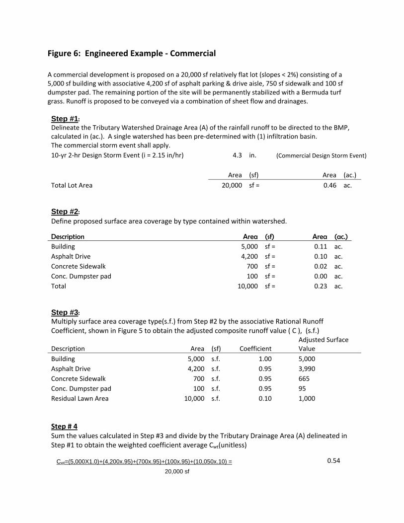
Figure 6: Engineered Example ‐ Commercial A commercial development is proposed on a 20,000 sf relatively flat lot (slopes < 2%) consisting of a 5,000 sf building with associative 4,200 sf of asphalt parking & drive aisle, 750 sf sidewalk and 100 sf dumpster pad. The remaining portion of the site will be permanently stabilized with a Bermuda turf grass. Runoff is proposed to be conveyed via a combination of sheet flow and drainages. Step #1: Delineate the Tributary Watershed Drainage Area (A) of the rainfall runoff to be directed to the BMP, calculated in (ac.). A single watershed has been pre‐determined with (1) infiltration basin. The commercial storm event shall apply. 10‐yr 2‐hr Design Storm Event (i = 2.15 in/hr) 4.3 in. (Commercial Design Storm Event)
Area (sf) Area (ac.) Total Lot Area 20,000 sf = 0.46 ac. Step #2: Define proposed surface area coverage by type contained within watershed.
Description Area (sf) Area (ac.) Building 5,000 sf = 0.11 ac. Asphalt Drive 4,200 sf = 0.10 ac. Concrete Sidewalk 700 sf = 0.02 ac. Conc. Dumpster pad 100 sf = 0.00 ac. Total 10,000 sf = 0.23 ac. Step #3: Multiply surface area coverage type(s.f.) from Step #2 by the associative Rational Runoff Coefficient, shown in Figure 5 to obtain the adjusted composite runoff value ( C ), (s.f.)
Description Area (sf) Coefficient Adjusted Surface Value
Building 5,000 s.f. 1.00 5,000 Asphalt Drive 4,200 s.f. 0.95 3,990 Concrete Sidewalk 700 s.f. 0.95 665 Conc. Dumpster pad 100 s.f. 0.95 95 Residual Lawn Area 10,000 s.f. 0.10 1,000 Step # 4 Sum the values calculated in Step #3 and divide by the Tributary Drainage Area (A) delineated in Step #1 to obtain the weighted coefficient average Cwt(unitless)
Cwt=(5,000X1.0)+(4,200x.95)+(700x.95)+(100x.95)+(10,050x.10) = 0.5420,000 sf

Step #5: To obtain Q (cfs), multiply (Cwt) as calculated in Step #4 by the design rainfall intensity (I) by the tributary watershed area (A)
Q=CIA C = 0.54 I = 2.15 in/hr A = 0.46 ac. Q=C*I*A = 0.5306 cfs
Step #6: Multiply Q (cfs), as calculated in Step #5, by the duration (d) (sec) to obtain the minimum req'dstorage volume (c.f.)
Design Storm Event Duration 2.0 hrs.= 7,200 sec. Post‐Development Runoff Volume = Q*time 3,820 cf
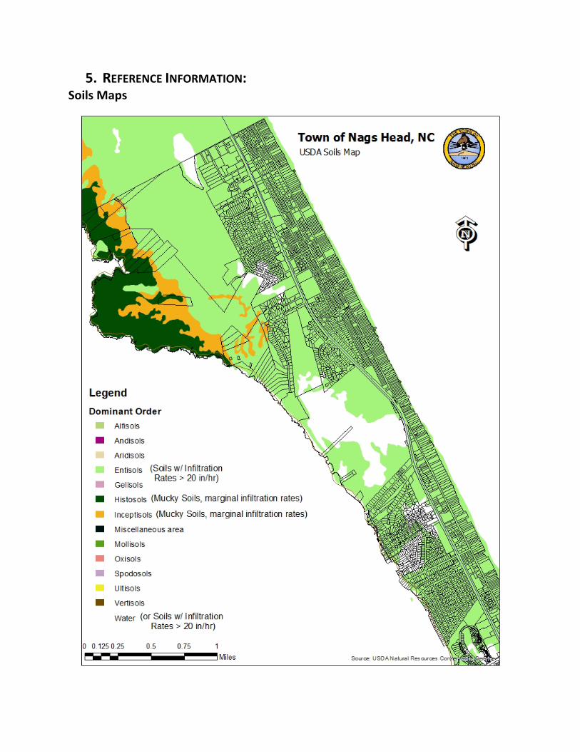
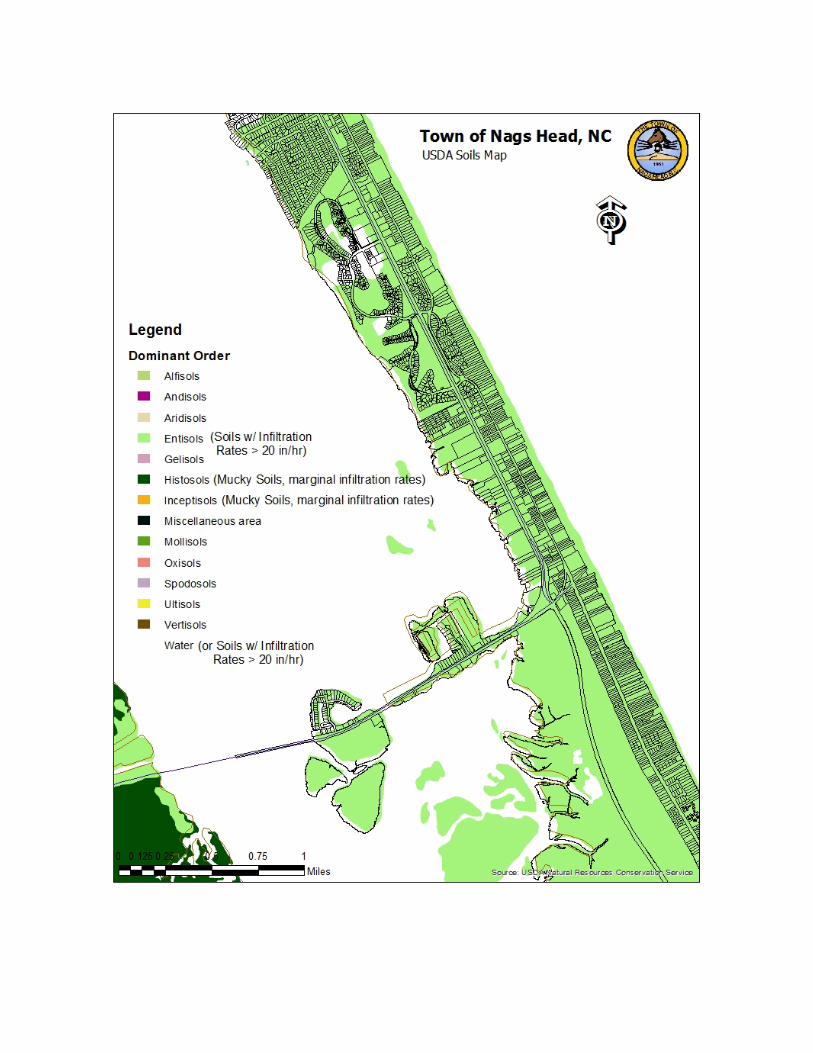
5. REFERENCE INFORMATION: Soils Maps
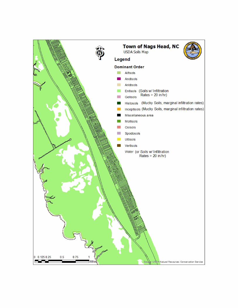

The Nags Head Environment This Manual is written in support of the Town of Nags Head Land Use Plan (adopted in 2010), which set out a vision and goals for the community that state:
The Town of Nags Head is working to build a community populated by diverse groups whose common bond is a love of the Outer Banks. We recognize that the Town must be a good place to live before it can be a good place to visit. We recognize that those who have lived on this land before us have forged our path and that we must learn from them and respect their memory. We recognize that our natural environment is an integral part of our community and must be considered in all decisions. We recognize that in order to secure this future we must work together, treating all with respect and fairness and focusing on our common goals. The Town’s goals were derived from issues and concerns from the beginning of this plan. The Town of Nags Head is working to build a community with an economy based on family vacation tourism. The base of that economy is a high quality beach experience. Important elements in developing and maintaining this economy are:
• A relaxed‐paced beach community comprised primarily of low‐density development and open spaces.
• A diverse supply of accommodations, including single‐family homes, hotels, and multi‐family dwelling units, that attract and are accessible to visitors from a wide range of economic and social strata.
• A natural environment typified by clean water and a landscape of sand dunes and non‐invasive, salt tolerant vegetation.
• A healthy, well‐maintained oceanfront beach that is accessible and usable; not blocked by large structures.
• A carefully managed sound front that preserves the natural and beneficial functions of the estuarine environment while balancing respect for private property rights and the need to provide public access.
• A built environment that reflects the heritage of “Old Nags Head.” • A well‐organized pattern of land uses that, when combined with a transportation system
that accommodates a variety of travel modes, promotes an active and accessible community.
• Commercial services provided by locally owned and operated businesses that share in the building of our community.
• Recreational amenities and attractions, both commercial and non‐commercial that are wholesome and appeal to a broad spectrum of family members, age groups and interests.
The Town’s Vision statement recognizes that the natural environment is integral to the success of the community and recognizes the importance of clean water, public access to the sound and ocean, and an organized pattern of land development. Good stormwater management at both the community and individual lot level is vital to the protection of water quality and the preservation of the Town’s neighborhoods and transportation system. Because of our location on the Outer Banks, a system of barrier islands, several challenges exist to our community in carrying goals to improve water quality through stormwater management. Therefore it is critical that our community does all it can to manage stormwater and promote infiltration with every opportunity.
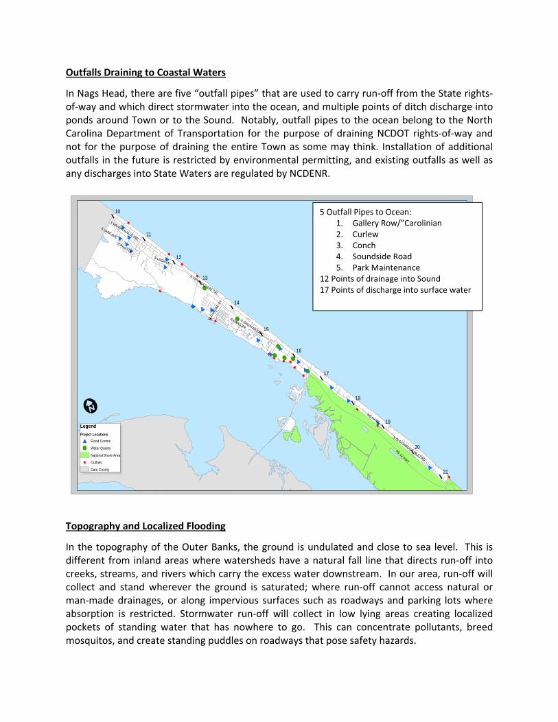
Outfalls Draining to Coastal Waters
In Nags Head, there are five “outfall pipes” that are used to carry run‐off from the State rights‐of‐way and which direct stormwater into the ocean, and multiple points of ditch discharge into ponds around Town or to the Sound. Notably, outfall pipes to the ocean belong to the North Carolina Department of Transportation for the purpose of draining NCDOT rights‐of‐way and not for the purpose of draining the entire Town as some may think. Installation of additional outfalls in the future is restricted by environmental permitting, and existing outfalls as well as any discharges into State Waters are regulated by NCDENR.
Topography and Localized Flooding
In the topography of the Outer Banks, the ground is undulated and close to sea level. This is different from inland areas where watersheds have a natural fall line that directs run‐off into creeks, streams, and rivers which carry the excess water downstream. In our area, run‐off will collect and stand wherever the ground is saturated; where run‐off cannot access natural or man‐made drainages, or along impervious surfaces such as roadways and parking lots where absorption is restricted. Stormwater run‐off will collect in low lying areas creating localized pockets of standing water that has nowhere to go. This can concentrate pollutants, breed mosquitos, and create standing puddles on roadways that pose safety hazards.
^
^
^
^
^
^
^
^
^^^
^^
^
^
^^
#
#
!
!
!
!
!
!
##
#
##
#
# # #
#
#
#
#
#
#
!
#
#
ª«
ª«
ª«
ª«
ª«
ª«
ª«
ª«
ª«
ª«
ª«
ª«
NC 12 HWY
S CROATAN HWY
S VIRGINIA DARE TRL
S OLD OREGON INLET RD
S WRIGHTSVILLE AVE
NO NAME
S LINDA LN
S LINKS DR
W D
ANUBE
ST
S LARK AVE
S PILOT LN
21
20
19
18
17
16
15
14
13
12
11
10
LegendProject Locations
# Flood Control
! Water Quality
National Shore Area
^ Outfalls
Dare County
I
5 Outfall Pipes to Ocean: 1. Gallery Row/”Carolinian 2. Curlew 3. Conch 4. Soundside Road 5. Park Maintenance
12 Points of drainage into Sound 17 Points of discharge into surface water
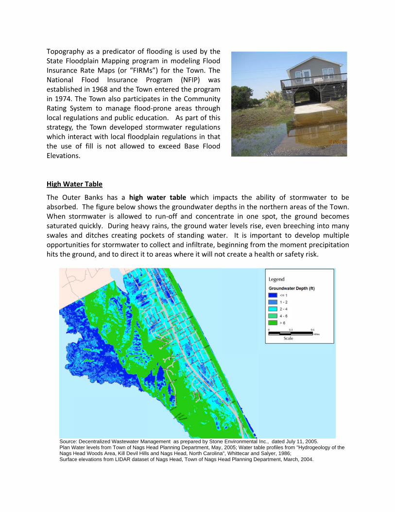
TopograpState FloInsuranceNational establishin 1974. Rating Sylocal regstrategy, which intthe use Elevation High Wa
The OutabsorbedWhen stsaturatedswales aopportunhits the g
Source Plan W Nags H Surfac
phy as a preoodplain Mae Rate Map
Flood Ined in 1968 aThe Town aystem to mulations andthe Town dteract with of fill is no
ns.
ter Table
er Banks hd. The figuretormwater id quickly. Dnd ditches nities for stoground, and
e: Decentralized Water levels fromHead Woods Arece elevations from
edicator of fapping progrps (or “FIRMnsurance Pand the Towalso participamanage floodd public edudeveloped slocal floodpot allowed
as a high we below shos allowed tDuring heavycreating poormwater toto direct it t
Wastewater Mam Town of Nags Hea, Kill Devil Hillsm LIDAR dataset
flooding is uram in modMs”) for the Program (Nwn entered thates in the Cd‐prone arecation. As stormwater lain regulatito exceed
water tableows the grouo run‐off ay rains, the gockets of sta collect and to areas whe
nagement as prHead Planning Ds and Nags Headt of Nags Head, T
used by the eling Flood Town. The NFIP) was he program Community as through part of this regulations ions in that Base Flood
e which impundwater dend concentrground wateanding wateinfiltrate, beere it will no
repared by StoneDepartment, May,d, North CarolinaTown of Nags H
pacts the aepths in the rate in one er levels riseer. It is impeginning froot create a h
e Environmental , 2005; Water tab
a", Whittecar andead Planning De
ability of stnorthern arspot, the g
e, even breeportant to dom the momealth or safe
Inc., dated July ble profiles from
d Salyer, 1986; epartment, March
ormwater treas of the Tground becoeching into mdevelop mu
ment precipitety risk.
11, 2005. "Hydrogeology o
h, 2004.
to be Town. omes many ultiple tation
of the

Estuaries and Shellfish Waters Pollution decreases water quality and threatens aquatic ecosystems in a variety of ways. Excess nutrients from fertilizers can cause algal blooms, which use up much of the oxygen in the water and can prevent other aquatic plants and animals from receiving adequate amounts of oxygen. Algal blooms can also block sunlight and harm the ability of submerged aquatic vegetation to perform photosynthesis, threatening aquatic animals who use these plants as a food source. Pollution can contain toxins and bacteria that contaminate aquatic ecosystems, often resulting in fish kills and declines in the populations of other aquatic life. This can also force closings of shellfish beds to harvesting and beaches to recreational uses. The Outer Banks community is especially familiar with the importance of healthy estuaries in order to support the fishing and tourism industries that its economy depends on.
Application Forms and Materials
Are available on the Town of Nags Head website at www.nagsheadnc.gov
Sources: Doll, Barbara, and Lundie Spence. Coastal Water Quality Handbook. North Carolina Sea Grant. Print. Environmental Protection Agency. Office of Water/Office of Wastewater Management. Stormwater Discharges From Municipal Separate Storm Sewer Systems (MS4s). 24 July 2013. Web. 18 Sept. 2013. <http://cfpub.epa.gov/npdes/stormwater/munic.cfm>. Northern Middlesex Council of Governments. 2007 Tyngsborough Stormwater Management Plan Narrative. Web. 18 Sept. 2013. <http://www.nmcog.org/Report%20narrative.pdf>. Periman, Howard. "The Water Cycle: Surface Runoff." USGS.gov. U.S. Department of the Interior/U.S. Geological Survey. 23 May 2013. Web. 18 Sept. 2013. <http://ga.water.usgs.gov/edu/watercyclerunoff.html>. North Carolina Coastal Federation. Low Impact Development, Simple Solutions to Reduce Stormwater Impacts, A Manual for the town of Columbia, NC. October, 2010. New Hanover County. Stormwater Design Manual. 5 Sept. 2000. Center for Watershed Protection. District Department of the Environment. Watershed Protection Division. District of Columbia. Stormwater Management Guidebook. July, 2013. North Carolina State University. Low Impact Development A Guidebook for North Carolina. June 2009. Environmental Protection Agency. National Pollutant Discharge Elimination System (NPDES). Preserving Natural Vegetation. Web. 3 Oct. 2013. <cfpub.epa.gov/NPDES/menuofbmps/index.cfm> Moffat and Nichol. Blue Land, Water, Infrastructure. An Assessment of Outer Banks Coastal Environment Conditions, Existing Stormwater management Strategies, and the Local and State Regulatory Context to Help Local Communities Effectively Implement Low Impact Development-Outer Bank, NC. 22 June 2006. Whisnant, Richard. UNC School of Government. Universal Stormwater Model Ordinance for North Carolina. 11 Feb. 2007. City of Los Angeles. Department of Public Works. Watershed Protection Division. Development Best Management Practices Handbook. Low Impact Development Manual. Part B. Planning Activities. 4th Edition. June 2011. Town of Nags Head. Stormwater Management Ordinance (Town Chapter 14, Article II, Drainage), Design Professional Workshop. 27 March 1997. EFS, Inc. Engineered Fabric Specialists, Inc. Web. 7 Oct. 2013 <http://www.efsinc.net/treeProtect.php>

Town of Nags Head Ordinance Excerpt: