Embed Size (px)
Citation preview
67
Annuaire de l’Universite de Sofia “St. Kliment Ohridski”, Faculte de Physique, 102, 2009
Lüneburg Lenses as CommuniCation antennas
sLavi baev1, boyan Hadjistamov2, PLamen dankov3
1 RaySat BG, Sofia, Bulgaria2 , 3Department of Radio Physics and Electronics, Faculty of Physics,
St. Kliment Ohridski University of Sofia
Слави Баев, Боян Хаджистамов, Пламен Данков.� Лещи на Лунебърг като комуникационни антени
Статията се отнася за принципите за моделиране и симулация с ���симулатори на���симулатори на��симулатори на�симулатори насимулатори на добре познатите лещи на Люнебърг, използвани като комуникационни антенни устрой�ства. разгледани са модели на сферични, полусферични и цилиндрични многослойни лещи. резутатите показват ефективността на предложената симулационна процедура за изследване на фокусиращия ефект и антенните параметри на тези обемни излъчващи структури.
Slavi Baev, Boyan Hadjistamov, Plamen Dankov.� Lüneburg Lenses as Commu�niCation antennas
the paper is dealing with the principles for modeling and simulating by 3d simulators of the well�known Lüneburg lenses used as communication antenna devices. The models of spherical, semi�spherical and cylindrical multi�layer dielectric lenses are discussed. The results show the effectiveness of the proposed simulation procedures for investigation of the focusing effects and antenna parameters of these large�scale beam�forming devices.
Keywords : antennas, dielectric antennas, electromagnetic 3d simulators, focusing, lens antennas.�
PACS number : 77 22–d
For contact: Plamen I. �ankov, �epartment of Radio Physics and Electronics, Faculty of Physics, University of Sofia, 5, J. Bourchier Blvd., 1164 Sofia, Bulgaria, Phone: +�59�02�8161806, e�mail: [email protected]�sofia.bg
68
1.� introduCtion and basiC modeL
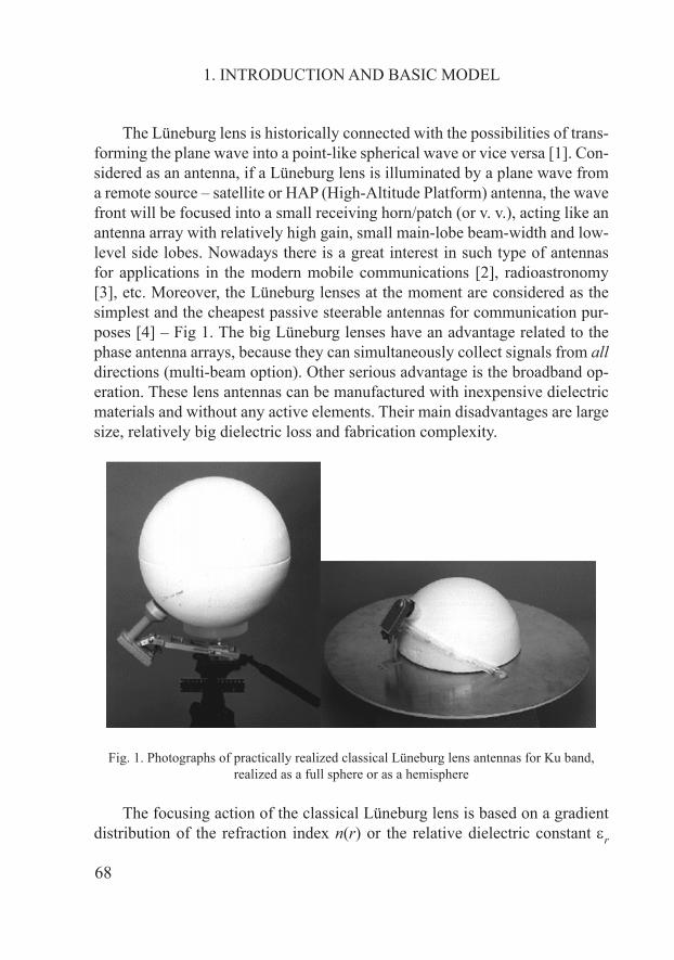
The Lüneburg lens is historically connected with the possibilities of trans�forming the plane wave into a point�like spherical wave or vice versa [1]. Con�sidered as an antenna, if a Lüneburg lens is illuminated by a plane wave from a remote source – satellite or HAP (High�Altitude Platform) antenna, the wave front will be focused into a small receiving horn/patch (or v. v.), acting like an antenna array with relatively high gain, small main�lobe beam�width and low�level side lobes. Nowadays there is a great interest in such type of antennas for applications in the modern mobile communications [2], radioastronomy [�], etc. Moreover, the Lüneburg lenses at the moment are considered as the simplest and the cheapest passive steerable antennas for communication pur�poses [4] – Fig 1. The big Lüneburg lenses have an advantage related to the phase antenna arrays, because they can simultaneously collect signals from all directions (multi�beam option). Other serious advantage is the broadband op�eration. These lens antennas can be manufactured with inexpensive dielectric materials and without any active elements. Their main disadvantages are large size, relatively big dielectric loss and fabrication complexity.
Fig. 1. Photographs of practically realized classical Lüneburg lens antennas for Ku band, realized as a full sphere or as a hemisphere
The focusing action of the classical Lüneburg lens is based on a gradient distribution of the refraction index n(r) or the relative dielectric constant εr
69
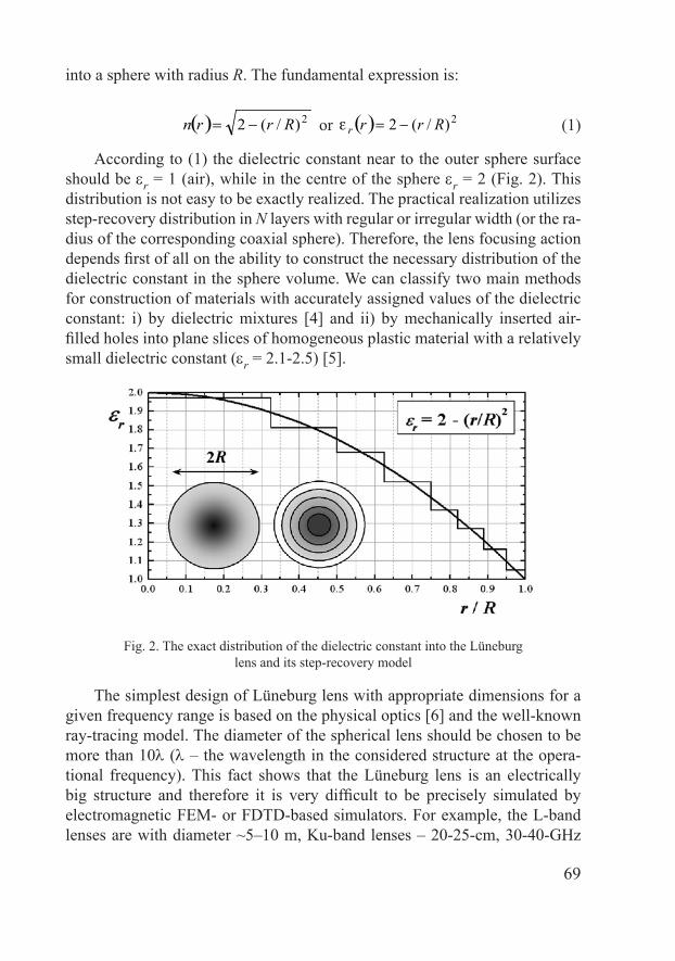
into a sphere with radius R.� the fundamental expression is:
( ) 2)/(2 Rrrn −= or ( ) 2)/(2 Rrrr −=ε (1)
According to (1) the dielectric constant near to the outer sphere surface should be εr = 1 (air), while in the centre of the sphere εr = 2 (Fig. 2). This distribution is not easy to be exactly realized.� the practical realization utilizes step�recovery distribution in N layers with regular or irregular width (or the ra�dius of the corresponding coaxial sphere). Therefore, the lens focusing action depends first of all on the ability to construct the necessary distribution of the dielectric constant in the sphere volume. We can classify two main methods for construction of materials with accurately assigned values of the dielectric constant: i) by dielectric mixtures [4] and ii) by mechanically inserted air�filled holes into plane slices of homogeneous plastic material with a relatively small dielectric constant (εr = 2.1�2.5) [5].
Fig. 2. The exact distribution of the dielectric constant into the Lüneburg lens and its step�recovery model
The simplest design of Lüneburg lens with appropriate dimensions for a given frequency range is based on the physical optics [6] and the well�known ray�tracing model. The diameter of the spherical lens should be chosen to be more than 10λ (λ – the wavelength in the considered structure at the opera�tional frequency). This fact shows that the Lüneburg lens is an electrically big structure and therefore it is very difficult to be precisely simulated by electromagnetic FEM� or F�T��based simulators. For example, the L�band lenses are with diameter ~5–10 m, Ku�band lenses – 20�25�cm, �0�40�GHz
70
lenses – 10–15 cm, �00�GHz lenses – 20 mm. In this paper we present our experience to simulate big Lüneburg lenses by �� electro�magnetic simula�tors (e.g. Ansoft® HFSS�8 and 11 [7]). We investigate the focusing effect in different lens structures with a different number of layers and shapes; consider the parasitic resonance effects and the influence of the dielectric anisotropy. Finally, the main antenna parameters: gain and radiation patterns, are deter�mined by simulations.�
2. INvESTIGATION OF THE FOCUSING EFFECTS
A. Modeling of Lüneburg lenses by 3D simulators
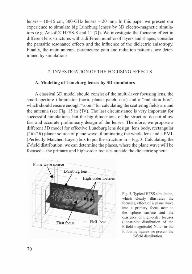
A classical �� model should consist of the multi�layer focusing lens, the small�aperture illuminator (horn, planar patch, etc.) and a “radiation box”, which should ensure enough “room” for calculating the scattering fields around the antenna (see Fig. 15 in §Iv). The last circumstance is very important for successful simulations, but the big dimensions of the structure do not allow fast and accurate preliminary design of the lenses.� therefore, we propose a different �� model for effective Lüneburg lens design: lens body, rectangular (2R×2R) planar source of plane wave, illuminating the whole lens and a PML (Perfectly�Matched�Layer) box to put the structure in – Fig. �. Calculating the E�field distribution, we can determine the places, where the plane wave will be focused – the primary and high�order focuses outside the dielectric sphere.
Fig. �. Typical HFSS simulation, which clearly illustrates the focusing effect of a plane wave into a primary focus near to the sphere surface and the existence of high�order focuses (linear�plot distribution of the E�field magnitude) Note: in the following figures we present the
E�field distribution.
71
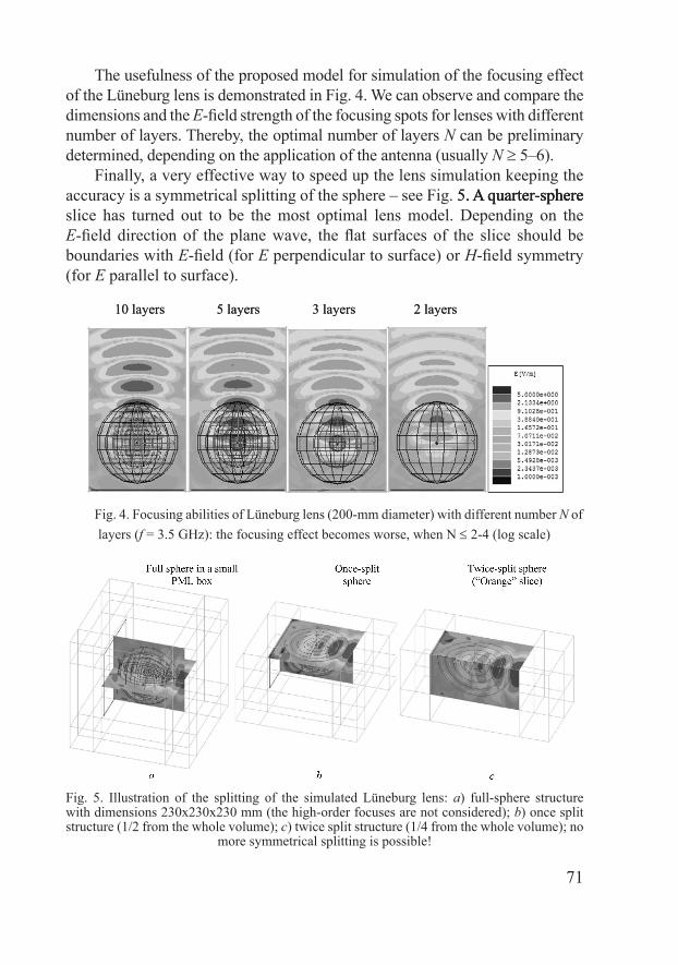
the usefulness of the proposed model for simulation of the focusing effect of the Lüneburg lens is demonstrated in Fig. 4. We can observe and compare the dimensions and the E�field strength of the focusing spots for lenses with different number of layers.� thereby, the optimal number of layers N can be preliminary determined, depending on the application of the antenna (usually N ≥ 5–6).
Finally, a very effective way to speed up the lens simulation keeping the accuracy is a symmetrical splitting of the sphere – see Fig. 5. A quarter�sphere5. A quarter�sphere. A quarter�sphere slice has turned out to be the most optimal lens model.� depending on the E�field direction of the plane wave, the flat surfaces of the slice should be boundaries with E�field (for E perpendicular to surface) or H�field symmetry (for E parallel to surface).
10 layers 5 layers � layers 2 layers10 layers 5 layers � layers 2 layers
Fig. 4. Focusing abilities of Lüneburg lens (200�mm diameter) with different number N of layers (f = �.5 GHz): the focusing effect becomes worse, when N ≤ 2�4 (log scale)
Fig. 5. Illustration of the splitting of the simulated Lüneburg lens: a) full�sphere structure with dimensions 2�0x2�0x2�0 mm (the high�order focuses are not considered); b) once split structure (1/2 from the whole volume); c) twice split structure (1/4 from the whole volume); no
more symmetrical splitting is possible!
72
B. Resonance effects at low frequencies
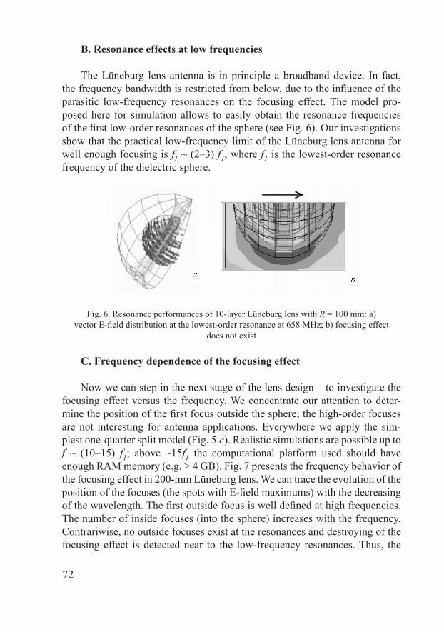
The Lüneburg lens antenna is in principle a broadband device. In fact, the frequency bandwidth is restricted from below, due to the influence of the parasitic low�frequency resonances on the focusing effect. The model pro�posed here for simulation allows to easily obtain the resonance frequencies of the first low�order resonances of the sphere (see Fig. 6). Our investigations show that the practical low�frequency limit of the Lüneburg lens antenna for well enough focusing is fL ~ (2–�) f1, where f1 is the lowest�order resonance frequency of the dielectric sphere.
Fig. 6. Resonance performances of 10�layer Lüneburg lens with R = 100 mm: a) vector E�field distribution at the lowest�order resonance at 658 MHz; b) focusing effect
does not exist
C. Frequency dependence of the focusing effect
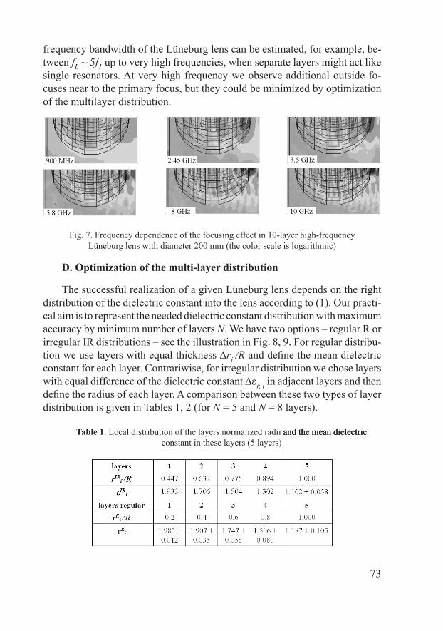
Now we can step in the next stage of the lens design – to investigate the focusing effect versus the frequency. We concentrate our attention to deter�mine the position of the first focus outside the sphere; the high�order focuses are not interesting for antenna applications. Everywhere we apply the sim�plest one�quarter split model (Fig. 5.c). Realistic simulations are possible up to f ~ (10–15) f1; above ~15f1 the computational platform used should have enough RAM memory (e.g. > 4 GB). Fig. 7 presents the frequency behavior of the focusing effect in 200�mm Lüneburg lens. We can trace the evolution of the position of the focuses (the spots with E�field maximums) with the decreasing of the wavelength. The first outside focus is well defined at high frequencies. The number of inside focuses (into the sphere) increases with the frequency. Contrariwise, no outside focuses exist at the resonances and destroying of the focusing effect is detected near to the low�frequency resonances. Thus, the
73
frequency bandwidth of the Lüneburg lens can be estimated, for example, be�tween fL ~ 5f1 up to very high frequencies, when separate layers might act like single resonators. At very high frequency we observe additional outside fo�cuses near to the primary focus, but they could be minimized by optimization of the multilayer distribution.�
Fig. 7. Frequency dependence of the focusing effect in 10�layer high�frequency Lüneburg lens with diameter 200 mm (the color scale is logarithmic)
D. Optimization of the multi-layer distribution
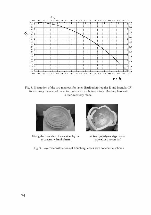
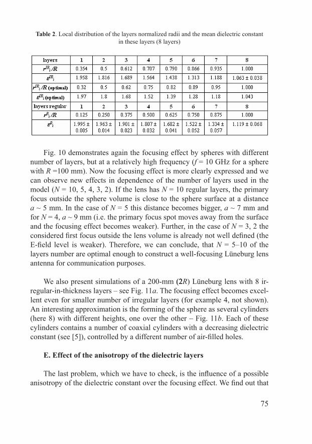
The successful realization of a given Lüneburg lens depends on the right distribution of the dielectric constant into the lens according to (1). Our practi�cal aim is to represent the needed dielectric constant distribution with maximum accuracy by minimum number of layers N. We have two options – regular R or irregular IR distributions – see the illustration in Fig. 8, 9. For regular distribu�tion we use layers with equal thickness ∆ri /R and define the mean dielectric constant for each layer.� Contrariwise, for irregular distribution we chose layers with equal difference of the dielectric constant ∆εr, i in adjacent layers and then define the radius of each layer. A comparison between these two types of layer distribution is given in Tables 1, 2 (for N = 5 and N = 8 layers).
Table 1.� Local distribution of the layers normalized radii and the mean dielectric and the mean dielectricand the mean dielectric constant in these layers (5 layers)
74
Fig. 8. Illustration of the two methods for layer distribution (regular R and irregular IR) for ensuring the needed dielectric constant distribution into a Lüneburg lens with
a step�recovery model
Fig. 9. Layered constructions of Lüneburg lenses with concentric spheres
75
Table 2.� Local distribution of the layers normalized radii and the mean dielectric constantin these layers (8 layers)
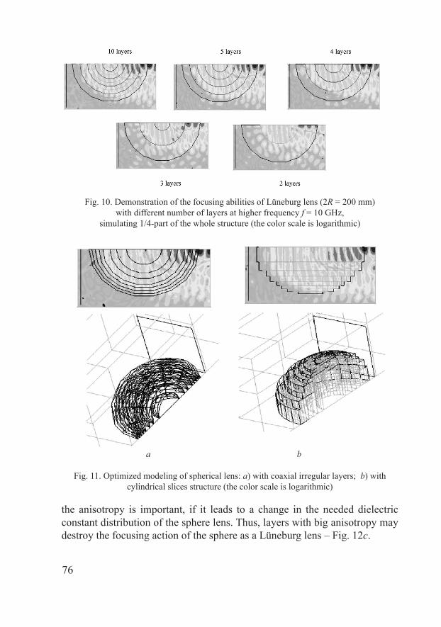
Fig. 10 demonstrates again the focusing effect by spheres with different number of layers, but at a relatively high frequency (f = 10 GHz for a sphere with R =100 mm). Now the focusing effect is more clearly expressed and we can observe new effects in dependence of the number of layers used in the model (N = 10, 5, 4, �, 2). If the lens has N = 10 regular layers, the primary focus outside the sphere volume is close to the sphere surface at a distance a ~ 5 mm. In the case of N = 5 this distance becomes bigger, a ~ 7 mm and for N = 4, a ~ 9 mm (i.e. the primary focus spot moves away from the surface and the focusing effect becomes weaker). Further, in the case of N = 3, 2 the considered first focus outside the lens volume is already not well defined (the E�field level is weaker). Therefore, we can conclude, that N = 5–10 of the layers number are optimal enough to construct a well�focusing Lüneburg lens antenna for communication purposes.�
We also present simulations of a 200�mm (2(22R) Lüneburg lens with 8 ir�regular�in�thickness layers – see Fig. 11a.� the focusing effect becomes excel�lent even for smaller number of irregular layers (for example 4, not shown). An interesting approximation is the forming of the sphere as several cylinders (here 8) with different heights, one over the other – Fig. 11b.� each of these cylinders contains a number of coaxial cylinders with a decreasing dielectric constant (see [5]), controlled by a different number of air�filled holes.
E. Effect of the anisotropy of the dielectric layers
The last problem, which we have to check, is the influence of a possible anisotropy of the dielectric constant over the focusing effect. We find out that
76
Fig. 10. �emonstration of the focusing abilities of Lüneburg lens (2R = 200 mm) with different number of layers at higher frequency f = 10 GHz,
simulating 1/4�part of the whole structure (the color scale is logarithmic)
Fig. 11. Optimized modeling of spherical lens: a) with coaxial irregular layers; b) with cylindrical slices structure (the color scale is logarithmic)
a b
the anisotropy is important, if it leads to a change in the needed dielectric constant distribution of the sphere lens.� thus, layers with big anisotropy may destroy the focusing action of the sphere as a Lüneburg lens – Fig. 12c.�

77
Fig. 12. �emonstration of the de�focusing effect in Lüneburg lens by the anisotropy of the dielectric constant in the layers: a) isotropic case; b) case of longitudinal anisotropy;
c) case of transversal anisotropy (the color scale is logarithmic)
�. LüNEBURG LENSES OF �IFFERENT SHAPES
A. Conventional spherical lens
The spherical Lüneburg lens is a classical antenna element, which focus is at the opposite end of the incoming wave. Up to now, we have investigated only this type of lenses. However, other more effective types of lenses can be utilized for communication purposes.�
B. Semi-spherical lens
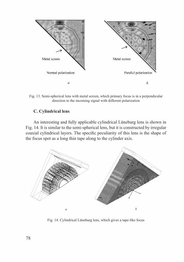
One of the most suitable antennas for satellite communications is the semi�spherical Lüneburg lens with a flat, metalized bottom surface. In this case the primary focus is placed at 90o according to the direction of the incoming from the satellite signal [2]. This lens ensures more reliable mechanical construc�tions for steerable satellite or HAP antennas. Fig. 1� shows the focusing effect in a simulated semi�spherical Lüneburg lens with 5 irregular layers. Now we simulate a half part of the semi�sphere, but the simulations are less efficient due to reflections. We observe good focusing effect in both of the directions of polarization – normal (E field of the plane wave is perpendicular to the metal screen) and parallel (E field is parallel to the metal screen). This is very impor�tant for the realization of dual�polarization satellite antennas.
78
Fig. 1�. Semi�spherical lens with metal screen, which primary focus is in a perpendicular direction to the incoming signal with different polarization
C. Cylindrical lens
An interesting and fully applicable cylindrical Lüneburg lens is shown in Fig. 14. It is similar to the semi�spherical lens, but it is constructed by irregular coaxial cylindrical layers. The specific peculiarity of this lens is the shape of the focus spot as a long thin tape along to the cylinder axis.�
Fig. 14. Cylindrical Lüneburg lens, which gives a tape�like focus
79
4. SIMULATION OF THE ANTENNA PARAMETERS
The presented preliminary design of the Lüneburg lens, based on the fo�cusing effect, can give the optimal value of the sphere diameter for the chosen frequency range, the lens shape and focus position, the optimized distribution of the layers, etc., but can not give the antenna parameters – radiation patterns, gain, efficiency, etc. Besides, the interaction between the illuminating horn and the whole antenna is not known.
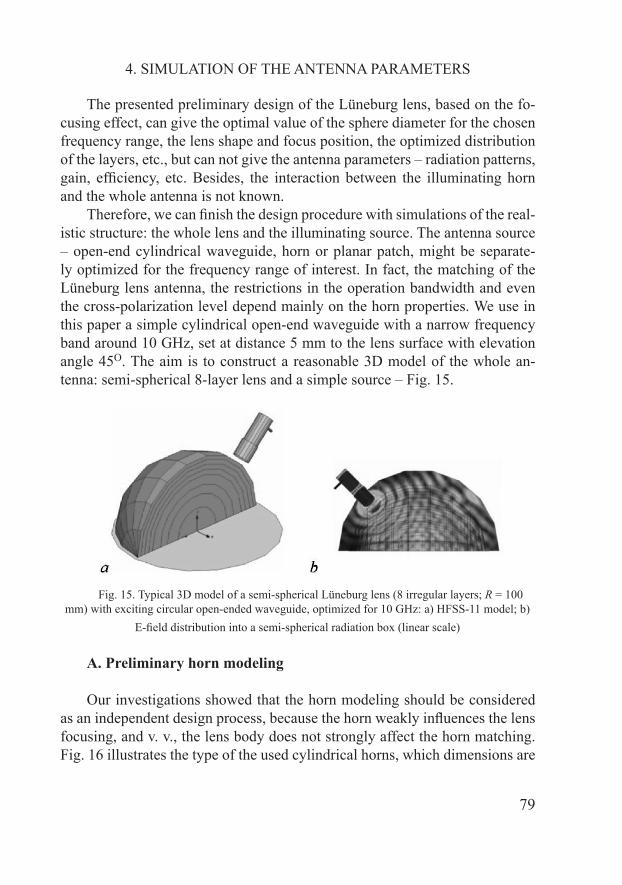
Therefore, we can finish the design procedure with simulations of the real�istic structure: the whole lens and the illuminating source.� the antenna source – open�end cylindrical waveguide, horn or planar patch, might be separate�ly optimized for the frequency range of interest. In fact, the matching of the Lüneburg lens antenna, the restrictions in the operation bandwidth and even the cross�polarization level depend mainly on the horn properties. We use in this paper a simple cylindrical open�end waveguide with a narrow frequency band around 10 GHz, set at distance 5 mm to the lens surface with elevation angle 45o.� the aim is to construct a reasonable 3d model of the whole an�tenna: semi�spherical 8�layer lens and a simple source – Fig. 15.
Fig. 15. Typical �� model of a semi�spherical Lüneburg lens (8 irregular layers; R = 100 mm) with exciting circular open�ended waveguide, optimized for 10 GHz: a) HFSS�11 model; b)
E�field distribution into a semi�spherical radiation box (linear scale)
A. Preliminary horn modeling
Our investigations showed that the horn modeling should be considered as an independent design process, because the horn weakly influences the lens focusing, and v. v., the lens body does not strongly affect the horn matching. Fig. 16 illustrates the type of the used cylindrical horns, which dimensions are
80
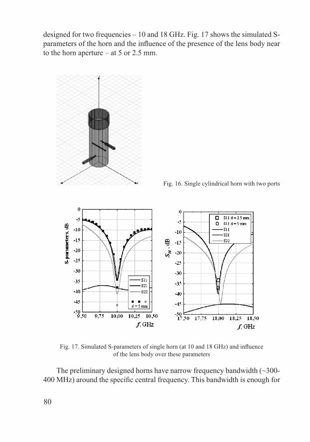
designed for two frequencies – 10 and 18 GHz. Fig. 17 shows the simulated S�parameters of the horn and the influence of the presence of the lens body near to the horn aperture – at 5 or 2.5 mm.
Fig. 16. Single cylindrical horn with two ports
Fig. 17. Simulated S�parameters of single horn (at 10 and 18 GHz) and influence of the lens body over these parameters
The preliminary designed horns have narrow frequency bandwidth (~�00�400 MHz) around the specific central frequency. This bandwidth is enough for
81
our preliminary lens design, but a broadband horn design is possible in future.� The horns are well matched; the isolation between the ports is above �45 dB at 18 GHz. The near presence of the dielectric lens body does not strongly affect the horn matching. We will investigate this effect more precisely in future.
B. HFSS models of Lüneburg lens illuminated by two-polarization horn
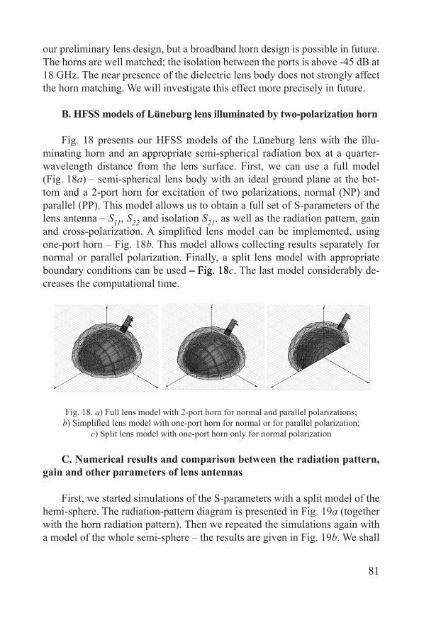
Fig. 18 presents our HFSS models of the Lüneburg lens with the illu�minating horn and an appropriate semi�spherical radiation box at a quarter�wavelength distance from the lens surface. First, we can use a full model (Fig. 18a) – semi�spherical lens body with an ideal ground plane at the bot�tom and a 2�port horn for excitation of two polarizations, normal (NP) and parallel (PP). This model allows us to obtain a full set of S�parameters of the lens antenna – S11, S22 and isolation S21, as well as the radiation pattern, gain and cross�polarization. A simplified lens model can be implemented, using one�port horn – Fig. 18b.� this model allows collecting results separately for normal or parallel polarization. Finally, a split lens model with appropriate boundary conditions can be used – Fig. 18 – Fig. 18– Fig. 18c.� the last model considerably de�creases the computational time.�
Fig. 18. a) Full lens model with 2�port horn for normal and parallel polarizations; b) Simplified lens model with one�port horn for normal or for parallel polarization;
c) Split lens model with one�port horn only for normal polarization
C. Numerical results and comparison between the radiation pattern, gain and other parameters of lens antennas
First, we started simulations of the S�parameters with a split model of the hemi�sphere. The radiation�pattern diagram is presented in Fig. 19a (together with the horn radiation pattern). Then we repeated the simulations again with a model of the whole semi�sphere – the results are given in Fig. 19b. We shall
82
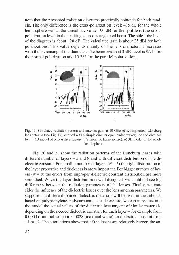
note that the presented radiation diagrams practically coincide for both mod�els. The only difference is the cross�polarization level: –�5 dB for the whole hemi�sphere versus the unrealistic value –90 dB for the split lens (the cross�polarization level in the exciting source is neglected here). The side�lobe level of the diagram is about –20 dB. The calculated gain is about 25 dBi for both polarizations. This value depends mainly on the lens diameter; it increases with the increasing of the diameter. The beam�width at ��dB�level is 9.71° for the normal polarization and 10.78° for the parallel polarization.
Fig. 19. Simulated radiation pattern and antenna gain at 10 GHz of semispherical Lüneburg lens antenna (see Fig. 15), excited with a simple circular open�ended waveguide and obtained by: a) �� model of once�split structure (1/2 from the hemi�sphere); b) �� model of the whole
hemi�sphere
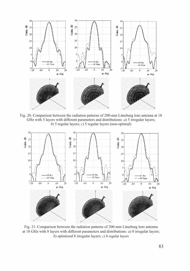
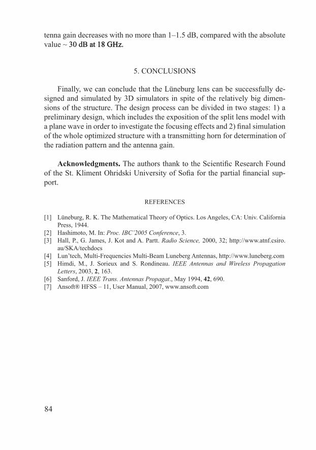
Fig. 20 and 21 show the radiation patterns of the Lüneburg lenses with different number of layers – 5 and 8 and with different distribution of the di�electric constant. For smaller number of layers (N = 5) the right distribution of the layer properties and thickness is more important. For bigger number of lay�ers (N = 8) the errors from improper dielectric constant distribution are more smoothed. When the layer distribution is well designed, we could not see big differences between the radiation parameters of the lenses. Finally, we con�sider the influence of the dielectric losses over the lens antenna parameters. We suppose that different foamed dielectric materials will be used in the antenna, based on polypropylene, polycarbonate, etc.� therefore, we can introduce into the model the actual values of the dielectric loss tangent of similar materials, depending on the needed dielectric constant for each layer – for example from 0.0004 (minimal value) to 0.0028 (maximal value) for dielectric constant from ~1 to ~2. The simulations show that, if the losses are relatively bigger, the an�
8�
Fig. 20. Comparison between the radiation patterns of 200�mm Lüneburg lens antenna at 18 GHz with 5 layers with different parameters and distributions: a) 5 irregular layers;
b) 5 regular layers; c) 5 regular layers (non�optimal)
Fig. 21. Comparison between the radiation patterns of 200�mm Lüneburg lens antenna at 18 GHz with 8 layers with different parameters and distributions: a) 8 irregular layers;
b) optimized 8 irregular layers; c) 8 regular layers
84
tenna gain decreases with no more than 1–1.5 dB, compared with the absolute value ~ �0 dB at 18 GHz.�0 dB at 18 GHz.at 18 GHz.
5. CONCLUSIONS
Finally, we can conclude that the Lüneburg lens can be successfully de�signed and simulated by �� simulators in spite of the relatively big dimen�sions of the structure. The design process can be divided in two stages: 1) a preliminary design, which includes the exposition of the split lens model with a plane wave in order to investigate the focusing effects and 2) final simulation of the whole optimized structure with a transmitting horn for determination of the radiation pattern and the antenna gain.�
Acknowledgments.. The authors thank to the Scientific Research Found of the St. Kliment Ohridski University of Sofia for the partial financial sup�port.�
REFERENCES
[1] Lüneburg, R. K. The Mathematical Theory of Optics. Los Angeles, CA: Univ. California Press, 1944.
[2] Hashimoto, M. In: Proc. IBC’2005 Conference, 3.�[�] Hall, P., G. James, J. Kot and A. Partt. Radio Science, 2000, �2; http://www.atnf.csiro.
au/SKA/techdocs[4] Lun’tech, Multi�Frequencies Multi�Beam Luneberg Antennas, http://www.luneberg.com [5] Himdi, M., J. Sorieux and S. Rondineau. IEEE Antennas and Wireless Propagation
Letters, 200�, 2, 163.� [6] Sanford, J. IEEE Trans. Antennas Propagat., May 1994, 42, 690. [7] Ansoft® HFSS – 11, User Manual, 2007, www.�ansoft.�com