Embed Size (px)
Citation preview
Screw PumpOperating manual SN..ER.. series
Version BA-2007.03Print-No. 550 411VM-No. 650.0002 GB
ALLWEILER AG • Radolfzell plantPostfach 1140Allweilerstr. 178301 RadolfzellGermanyPhone: +49 (0) 7732-86-0Fax: +49 (0) 7732-86-436E-mail: [email protected]: http://www.allweiler.com
We reserve the right to make technical changes.
Table of contents
Table of contents
1 About this document . . . . . . . . . . . . . . . . . . . . . . . . . . . . . . . 5
1.1 Target groups . . . . . . . . . . . . . . . . . . . . . . . . . . . . . . . . . 5
1.2 Other applicable documents . . . . . . . . . . . . . . . . 5
1.3 Warnings and symbols . . . . . . . . . . . . . . . . . . . . . . . 6
2 Safety . . . . . . . . . . . . . . . . . . . . . . . . . . . . . . . . . . . . . . . . . . . . . . . . . 7
2.1 Intended use . . . . . . . . . . . . . . . . . . . . . . . . . . . . . . . . . . 7
2.2 General safety instructions . . . . . . . . . . . . . . . . . . 72.2.1 Product safety . . . . . . . . . . . . . . . . . . . . . . . . . . . . . . . . 72.2.2 Obligations of the operating company . . . . . . 82.2.3 Obligations of personnel . . . . . . . . . . . . . . . . . . . . . 8
2.3 Specific hazards . . . . . . . . . . . . . . . . . . . . . . . . . . . . . . 82.3.1 Explosion-hazard area . . . . . . . . . . . . . . . . . . . . . . . 82.3.2 Hazardous pumped liquids . . . . . . . . . . . . . . . . . . 8
3 Layout and function . . . . . . . . . . . . . . . . . . . . . . . . . . . . . . . . 9
3.1 Label . . . . . . . . . . . . . . . . . . . . . . . . . . . . . . . . . . . . . . . . . . 93.1.1 Type plate . . . . . . . . . . . . . . . . . . . . . . . . . . . . . . . . . . . . . 93.1.2 ATEX plate . . . . . . . . . . . . . . . . . . . . . . . . . . . . . . . . . . . . 93.1.3 Pump type code . . . . . . . . . . . . . . . . . . . . . . . . . . . . . . 9
3.2 Layout . . . . . . . . . . . . . . . . . . . . . . . . . . . . . . . . . . . . . . . . . 11
3.3 Shaft seals . . . . . . . . . . . . . . . . . . . . . . . . . . . . . . . . . . . . 123.3.1 Packing gland . . . . . . . . . . . . . . . . . . . . . . . . . . . . . . . . 123.3.2 Mechanical seals . . . . . . . . . . . . . . . . . . . . . . . . . . . . . 123.3.3 Shaft seal rings . . . . . . . . . . . . . . . . . . . . . . . . . . . . . . . 12
3.4 Storage and lubrication . . . . . . . . . . . . . . . . . . . . . . 123.4.1 Internal antifriction bearing . . . . . . . . . . . . . . . . . . 123.4.2 External antifriction bearing . . . . . . . . . . . . . . . . . 12
3.5 Sealing systems . . . . . . . . . . . . . . . . . . . . . . . . . . . . . . 12
3.6 Auxiliary systems (heating) . . . . . . . . . . . . . . . . . . 12
3.7 Types of setup . . . . . . . . . . . . . . . . . . . . . . . . . . . . . . . 13
4 Transport, storage and disposal . . . . . . . . . . . . . . . . . . 14
4.1 Transport . . . . . . . . . . . . . . . . . . . . . . . . . . . . . . . . . . . . . . 144.1.1 Unpacking and inspection on delivery . . . . . . 144.1.2 Lifting . . . . . . . . . . . . . . . . . . . . . . . . . . . . . . . . . . . . . . . . . . 14
4.2 Treatment for storage . . . . . . . . . . . . . . . . . . . . . . . . 154.2.1 Applying preservative to the inside . . . . . . . . . 154.2.2 Applying preservative to the outside . . . . . . . . 15
4.3 Storage . . . . . . . . . . . . . . . . . . . . . . . . . . . . . . . . . . . . . . . 15
4.4 Removing preservative . . . . . . . . . . . . . . . . . . . . . . 15
4.5 Disposal . . . . . . . . . . . . . . . . . . . . . . . . . . . . . . . . . . . . . . . 15
5 Setup and connection . . . . . . . . . . . . . . . . . . . . . . . . . . . . . . 16
5.1 Preparing the setup . . . . . . . . . . . . . . . . . . . . . . . . . . 165.1.1 Checking the ambient conditions . . . . . . . . . . . 165.1.2 Preparing the installation site . . . . . . . . . . . . . . . 165.1.3 Preparing the surface . . . . . . . . . . . . . . . . . . . . . . . . 165.1.4 Removing preservative . . . . . . . . . . . . . . . . . . . . . . 16
5.2 Setup . . . . . . . . . . . . . . . . . . . . . . . . . . . . . . . . . . . . . . . . . . 165.2.1 Setup with foundation . . . . . . . . . . . . . . . . . . . . . . . . 165.2.2 Set up with wall-mounted/foot-mounted
motor bracket . . . . . . . . . . . . . . . . . . . . . . . . . . . . . . . . . 17
5.2.3 Set up with motor bracket . . . . . . . . . . . . . . . . . . . 175.2.4 Set up with installation bracket . . . . . . . . . . . . . . 175.2.5 Set up with base . . . . . . . . . . . . . . . . . . . . . . . . . . . . . 17
5.3 Installing the motor . . . . . . . . . . . . . . . . . . . . . . . . . . . 185.3.1 Installing the motor on the base plate . . . . . . 185.3.2 Installing the motor at pumps in flange
version . . . . . . . . . . . . . . . . . . . . . . . . . . . . . . . . . . . . . . . . 18
5.4 Planning the pipes . . . . . . . . . . . . . . . . . . . . . . . . . . . 185.4.1 Specifying supports and flange
connections . . . . . . . . . . . . . . . . . . . . . . . . . . . . . . . . . . . 185.4.2 Specifying nominal diameters . . . . . . . . . . . . . . . 185.4.3 Specifying pipe lengths . . . . . . . . . . . . . . . . . . . . . . 185.4.4 Optimizing changes in cross-section and
direction . . . . . . . . . . . . . . . . . . . . . . . . . . . . . . . . . . . . . . 185.4.5 Avoiding excessive pressure . . . . . . . . . . . . . . . . 195.4.6 Providing safety and control devices
(recommended) . . . . . . . . . . . . . . . . . . . . . . . . . . . . . . 19
5.5 Connecting the pipes . . . . . . . . . . . . . . . . . . . . . . . . 195.5.1 Keeping the piping clean . . . . . . . . . . . . . . . . . . . . 195.5.2 Installing the suction pipe . . . . . . . . . . . . . . . . . . . . 195.5.3 Installing the pressure pipe . . . . . . . . . . . . . . . . . . 195.5.4 Inspection for stress-free pipe
connections . . . . . . . . . . . . . . . . . . . . . . . . . . . . . . . . . . . 19
5.6 Electrical connection . . . . . . . . . . . . . . . . . . . . . . . . . 205.6.1 Connecting the motor . . . . . . . . . . . . . . . . . . . . . . . . 20
5.7 Aligning the coupling precisely . . . . . . . . . . . . . . 20
5.8 Aligning the motor . . . . . . . . . . . . . . . . . . . . . . . . . . . . 215.8.1 Aligning the motor with sets of shims . . . . . . . 21
6 Operation . . . . . . . . . . . . . . . . . . . . . . . . . . . . . . . . . . . . . . . . . . . . 22
6.1 Putting the pump into service for the firsttime . . . . . . . . . . . . . . . . . . . . . . . . . . . . . . . . . . . . . . . . . . . . 22
6.1.1 Removing preservative . . . . . . . . . . . . . . . . . . . . . . 226.1.2 Preparing auxiliary systems (if
available) . . . . . . . . . . . . . . . . . . . . . . . . . . . . . . . . . . . . . 226.1.3 Filling and bleeding . . . . . . . . . . . . . . . . . . . . . . . . . . 226.1.4 Checking the sense of rotation . . . . . . . . . . . . . . 226.1.5 Switching on . . . . . . . . . . . . . . . . . . . . . . . . . . . . . . . . . . 236.1.6 Switching off . . . . . . . . . . . . . . . . . . . . . . . . . . . . . . . . . . 23
6.2 Operating . . . . . . . . . . . . . . . . . . . . . . . . . . . . . . . . . . . . . 236.2.1 Switching on . . . . . . . . . . . . . . . . . . . . . . . . . . . . . . . . . . 236.2.3 Switching off . . . . . . . . . . . . . . . . . . . . . . . . . . . . . . . . . . 23
6.3 Shutting down the pump . . . . . . . . . . . . . . . . . . . . . 24
6.4 Start-up following a shutdown period . . . . . . . 24
6.5 Operating the stand-by pump . . . . . . . . . . . . . . . 24
7 Maintenance . . . . . . . . . . . . . . . . . . . . . . . . . . . . . . . . . . . . . . . . . 25
7.1 Inspections . . . . . . . . . . . . . . . . . . . . . . . . . . . . . . . . . . . 25
7.2 Maintenance . . . . . . . . . . . . . . . . . . . . . . . . . . . . . . . . . . 257.2.1 Antifriction bearings . . . . . . . . . . . . . . . . . . . . . . . . . . 267.2.2 Mechanical seals . . . . . . . . . . . . . . . . . . . . . . . . . . . . . 267.2.3 Packing gland . . . . . . . . . . . . . . . . . . . . . . . . . . . . . . . . 267.2.4 Shaft seal rings . . . . . . . . . . . . . . . . . . . . . . . . . . . . . . . 26
7.3 Repairs . . . . . . . . . . . . . . . . . . . . . . . . . . . . . . . . . . . . . . . . 26
2 SN..ER.. series BA-2007.02 650.0002 GB – 550 411
Table of contents
7.3.1 Returning the pump to the manufac-turer . . . . . . . . . . . . . . . . . . . . . . . . . . . . . . . . . . . . . . . . . . . 26
7.3.2 Dismounting . . . . . . . . . . . . . . . . . . . . . . . . . . . . . . . . . . 277.3.3 Installing . . . . . . . . . . . . . . . . . . . . . . . . . . . . . . . . . . . . . . 27
7.4 Ordering spare parts . . . . . . . . . . . . . . . . . . . . . . . . . 27
8 Troubleshooting . . . . . . . . . . . . . . . . . . . . . . . . . . . . . . . . . . . . 28
8.1 Pump malfunctions . . . . . . . . . . . . . . . . . . . . . . . . . . . 28
8.2 Pressure relief valve malfunctions . . . . . . . . . . 30
9 Appendix . . . . . . . . . . . . . . . . . . . . . . . . . . . . . . . . . . . . . . . . . . . . . 31
9.1 Sectional drawings . . . . . . . . . . . . . . . . . . . . . . . . . . . 319.1.1 Part numbers and designations . . . . . . . . . . . . . 319.1.2 Sectional drawings . . . . . . . . . . . . . . . . . . . . . . . . . . . 329.1.3 Heating . . . . . . . . . . . . . . . . . . . . . . . . . . . . . . . . . . . . . . . . 35
9.2 Technical specifications . . . . . . . . . . . . . . . . . . . . . . 369.2.1 Ambient conditions . . . . . . . . . . . . . . . . . . . . . . . . . . . 369.2.2 Sound pressure levels . . . . . . . . . . . . . . . . . . . . . . . 369.2.3 Tightening torques . . . . . . . . . . . . . . . . . . . . . . . . . . . 369.2.4 Lubricants . . . . . . . . . . . . . . . . . . . . . . . . . . . . . . . . . . . . . 369.2.5 Preservatives . . . . . . . . . . . . . . . . . . . . . . . . . . . . . . . . . 379.2.6 Cleaning agents . . . . . . . . . . . . . . . . . . . . . . . . . . . . . . 379.2.7 Heating connection data . . . . . . . . . . . . . . . . . . . . . 37
9.3 Safety certificate . . . . . . . . . . . . . . . . . . . . . . . . . . . . . 39
650.0002 GB – 550 411 BA-2007.02 SN..ER.. series 3
Table of contents
List of figures
Fig. 1 Type plate (example) . . . . . . . . . . . . . . . . . . . . . . . . 9
Fig. 2 ATEX plate (example) . . . . . . . . . . . . . . . . . . . . . . . . 9
Fig. 3 Pump type code (example) . . . . . . . . . . . . . . . . . . 9
Fig. 4 SN..ER.. layout . . . . . . . . . . . . . . . . . . . . . . . . . . . . . . . 11
Fig. 5 SN..ER.. modules . . . . . . . . . . . . . . . . . . . . . . . . . . . . 13
Fig. 6 Fastening the lifting gear to the pump unithorizontally (as illustrated) . . . . . . . . . . . . . . . . . . . 14
Fig. 7 Fastening the lifting gear to the pump unitvertically (as illustrated) . . . . . . . . . . . . . . . . . . . . . . 14
Fig. 10 Straight pipe lengths upstream and down-stream of the pump (recommended) . . . . . . . 18
Fig. 14 SNH..ER..U12.1, SNH design, internalbearing, mechanical seal . . . . . . . . . . . . . . . . . . . . 32
Fig. 15 SNS with round foot . . . . . . . . . . . . . . . . . . . . . . . . . . 32
Fig. 16 SNS/SNGS with round foot and heatingchamber . . . . . . . . . . . . . . . . . . . . . . . . . . . . . . . . . . . . . . 32
Fig. 17 SN..ER..U12.1, internal bearing, mechanicalseal (sizes 940 - 3600) . . . . . . . . . . . . . . . . . . . . . . 33
Fig. 18 SN..ER..U3, internal bearing, two shaft sealrings . . . . . . . . . . . . . . . . . . . . . . . . . . . . . . . . . . . . . . . . . . . 33
Fig. 19 SN..ER..U2, internal bearing, glandpacking . . . . . . . . . . . . . . . . . . . . . . . . . . . . . . . . . . . . . . . . 33
Fig. 20 SN..ER..U4, internal bearing, three shaft sealrings . . . . . . . . . . . . . . . . . . . . . . . . . . . . . . . . . . . . . . . . . . . 33
Fig. 21 SN..ER..D12.1, external bearing, incapableof relubrication, mechanical seal . . . . . . . . . . . . 33
Fig. 22 SN..ER..E6.7, external bearing, capable ofrelubrication, mechanical seal . . . . . . . . . . . . . . . 33
Fig. 23 SN..ER..KA2, external bearing, incapable ofrelubrication, gland packing . . . . . . . . . . . . . . . . . 34
Fig. 24 SN..ER.. with steam heated cover/heatingcartridge . . . . . . . . . . . . . . . . . . . . . . . . . . . . . . . . . . . . . . 35
Fig. 25 SN..ER.. with electric heating . . . . . . . . . . . . . . . 35
List of tables
Tab. 1 Target groups and their duties . . . . . . . . . . . . . . 5
Tab. 2 Other applicable documents and theirpurpose . . . . . . . . . . . . . . . . . . . . . . . . . . . . . . . . . . . . . . . 5
Tab. 3 Warnings and consequences of disregardingthem .. . . . . . . . . . . . . . . . . . . . . . . . . . . . . . . . . . . . . . . . . . 6
Tab. 4 Symbols and their meaning . . . . . . . . . . . . . . . . . 6
Tab. 5 Measures to be taken if the pump is shutdown . . . . . . . . . . . . . . . . . . . . . . . . . . . . . . . . . . . . . . . . . . 24
Tab. 6 Measures depending on the behavior of thepumped liquid . . . . . . . . . . . . . . . . . . . . . . . . . . . . . . . . 24
Tab. 7 Measures for return . . . . . . . . . . . . . . . . . . . . . . . . . . 26
Tab. 8 Malfunction/number assignment . . . . . . . . . . . . 28
Tab. 9 Pump troubleshooting list . . . . . . . . . . . . . . . . . . . . 30
Tab. 10 Malfunction/number assignment . . . . . . . . . . . . 30
Tab. 11 Pressure relief valve troubleshootinglist . . . . . . . . . . . . . . . . . . . . . . . . . . . . . . . . . . . . . . . . . . . . . 30
Tab. 12 Designation of components . . . . . . . . . . . . . . . . . 31
Tab. 13 Ambient conditions . . . . . . . . . . . . . . . . . . . . . . . . . . . 36
Tab. 14 Sound pressure levels . . . . . . . . . . . . . . . . . . . . . . . 36
Tab. 15 Tightening torques . . . . . . . . . . . . . . . . . . . . . . . . . . . 36
Tab. 16 Grease types . . . . . . . . . . . . . . . . . . . . . . . . . . . . . . . . . 36
Tab. 17 Lubrication grease for increasedtemperatures . . . . . . . . . . . . . . . . . . . . . . . . . . . . . . . . . 37
Tab. 18 Minimum amounts for grease lubrica-tion . . . . . . . . . . . . . . . . . . . . . . . . . . . . . . . . . . . . . . . . . . . . 37
Tab. 19 Relubrication intervals . . . . . . . . . . . . . . . . . . . . . . . 37
Tab. 20 Cleaning agents . . . . . . . . . . . . . . . . . . . . . . . . . . . . . . 37
Tab. 21 Connection data for heating withsteam . . . . . . . . . . . . . . . . . . . . . . . . . . . . . . . . . . . . . . . . . 37
Tab. 22 Electric heating connection data . . . . . . . . . . . . 37
Tab. 23 Heating duration (all sizes) . . . . . . . . . . . . . . . . . . 38
4 SN..ER.. series BA-2007.02 650.0002 GB – 550 411
About this document
1 About this document
This manual• Is part of the pump
• Applies to all pump series listed
• Describes safe and appropriate operation during all oper-ating phases
1.1 Target groups
Target group Duty
Operating company Keep this manual available at the site of operation of the system,including for later use.Ensure that personnel read and follow the instructions in thismanual and the other applicable documents, especially all safetyinstructions and warnings.Observe any additional rules and regulations referring to thesystem.
Qualified personnel, fitter Read, observe and follow this manual and the other applicabledocuments, especially all safety instructions and warnings.
Tab. 1 Target groups and their duties
1.2 Other applicable documents
Document Purpose
ATEX additional instructions Operation in explosion-hazard areas
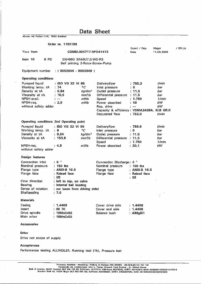
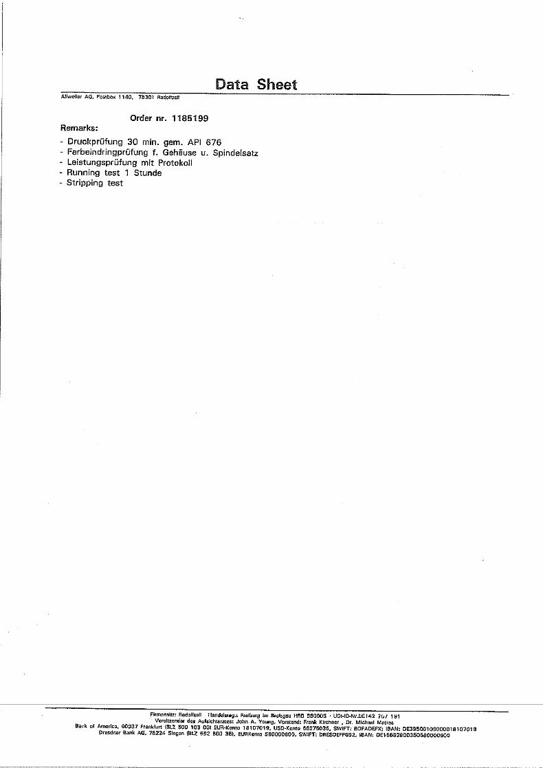
Order data sheet Technical specifications, conditions of operation
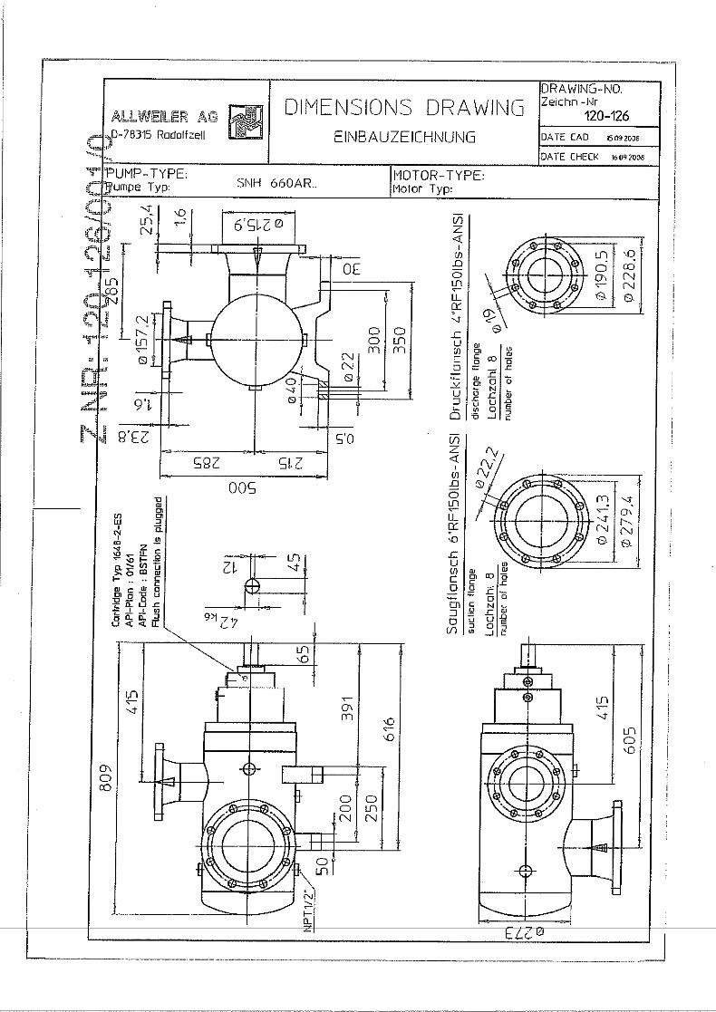
Setup drawing Setup dimensions, connection dimensions etc.
Technical description Technical specifications, operating limits
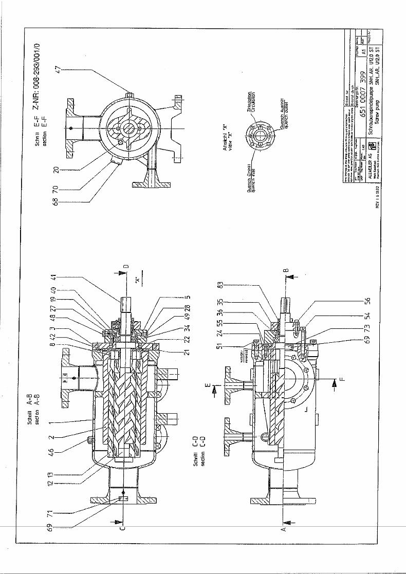
Sectional drawing Sectional drawing, part numbers, component designations
Supplier documentation Technical documentation for parts supplied by subcontractors
Tab. 2 Other applicable documents and their purpose
650.0002 GB – 550 411 BA-2007.02 SN..ER.. series 5
About this document
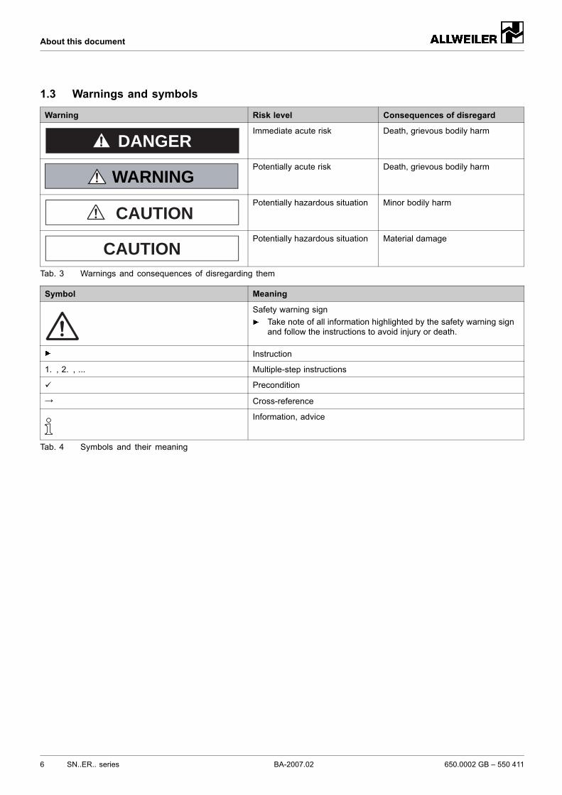
1.3 Warnings and symbols
Warning Risk level Consequences of disregard
DANGERImmediate acute risk Death, grievous bodily harm
WARNINGPotentially acute risk Death, grievous bodily harm
CAUTIONPotentially hazardous situation Minor bodily harm
CAUTIONPotentially hazardous situation Material damage
Tab. 3 Warnings and consequences of disregarding them
Symbol Meaning
Safety warning signTake note of all information highlighted by the safety warning signand follow the instructions to avoid injury or death.
Instruction
1. , 2. , ... Multiple-step instructions
Precondition
→ Cross-reference
Information, advice
Tab. 4 Symbols and their meaning
6 SN..ER.. series BA-2007.02 650.0002 GB – 550 411
Safety
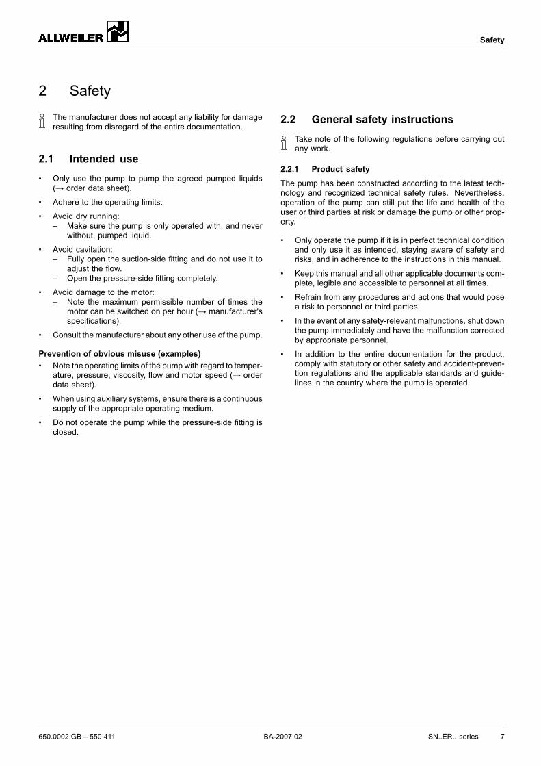
2 Safety
The manufacturer does not accept any liability for damageresulting from disregard of the entire documentation.
2.1 Intended use• Only use the pump to pump the agreed pumped liquids
(→ order data sheet).
• Adhere to the operating limits.
• Avoid dry running:– Make sure the pump is only operated with, and never
without, pumped liquid.
• Avoid cavitation:– Fully open the suction-side fitting and do not use it to
adjust the flow.– Open the pressure-side fitting completely.
• Avoid damage to the motor:– Note the maximum permissible number of times the
motor can be switched on per hour (→ manufacturer'sspecifications).
• Consult the manufacturer about any other use of the pump.
Prevention of obvious misuse (examples)• Note the operating limits of the pump with regard to temper-
ature, pressure, viscosity, flow and motor speed (→ orderdata sheet).
• When using auxiliary systems, ensure there is a continuoussupply of the appropriate operating medium.
• Do not operate the pump while the pressure-side fitting isclosed.
2.2 General safety instructionsTake note of the following regulations before carrying outany work.
2.2.1 Product safety
The pump has been constructed according to the latest tech-nology and recognized technical safety rules. Nevertheless,operation of the pump can still put the life and health of theuser or third parties at risk or damage the pump or other prop-erty.
• Only operate the pump if it is in perfect technical conditionand only use it as intended, staying aware of safety andrisks, and in adherence to the instructions in this manual.
• Keep this manual and all other applicable documents com-plete, legible and accessible to personnel at all times.
• Refrain from any procedures and actions that would posea risk to personnel or third parties.
• In the event of any safety-relevant malfunctions, shut downthe pump immediately and have the malfunction correctedby appropriate personnel.
• In addition to the entire documentation for the product,comply with statutory or other safety and accident-preven-tion regulations and the applicable standards and guide-lines in the country where the pump is operated.
650.0002 GB – 550 411 BA-2007.02 SN..ER.. series 7
Safety
2.2.2 Obligations of the operating company
Safety-conscious operation
• Only operate the pump if it is in perfect technical conditionand only use it as intended, staying aware of safety andrisks, and in adherence to the instructions in this manual.
• Ensure that the following safety aspects are observed andmonitored:– Intended use– Statutory or other safety and accident-prevention reg-
ulations– Safety regulations governing the handling of hazard-
ous substances– Applicable standards and guidelines in the country
where the pump is operated
• Make protective equipment available.
Qualified personnel• Make sure all personnel tasked with work on the pump
have read and understood this manual and all other appli-cable documents, especially the safety, maintenance andrepair information, before they start any work.
• Organize responsibilities, areas of competence and thesupervision of personnel.
• Ensure that all work is carried out by specialist techniciansonly:– Fitting, repair and maintenance work– Work on the electrical system
• Make sure trainee personnel only work on the pump undersupervision of specialist technicians.
Safety equipment• Provide the following safety equipment and verify its func-
tionality:– For hot, cold and moving parts: safety guarding pro-
vided by the customer for the pump– For possible build up of electrostatic charge: ensure
appropriate grounding.– If there is no pressure relief valve in the pump: pro-
vide an appropriate safety valve on the pressure sidebetween the pump and the first shut-off device
Warranty• Obtain the manufacturer's approval prior to carrying out
anymodifications, repairs or alterations during the warrantyperiod.
• Only use genuine parts or parts that have been approvedby the manufacturer.
2.2.3 Obligations of personnel• All directions given on the pumpmust be followed (and kept
legible), e.g. the arrow indicating the sense of rotation andthe markings for fluid connections.
• Do not remove the safety guarding for hot, cold or movingparts during operation.
• Use protective equipment whenever necessary.
• Only carry out work on the pump while it is not running.
• Isolate the motor from its supply voltage and secure itagainst being switched back on again when carrying outany fitting or maintenance work.
• Reinstall the safety equipment on the pump as required byregulations after any work on the pump.
2.3 Specific hazards
2.3.1 Explosion-hazard area• (→ ATEX additional instructions).
2.3.2 Hazardous pumped liquids• Follow the safety regulations for handling hazardous sub-
stances when handling hazardous (e.g. hot, flammable,poisonous or potentially harmful) pumped liquids.
• Use protective equipment when carrying out any work onthe pump.
8 SN..ER.. series BA-2007.02 650.0002 GB – 550 411
Layout and function
3 Layout and function
3.1 Label
3.1.1 Type plate
barkW
1/minl/min
NrTyp
mm2/s
D - 78315 Radolfzell / Germany12345
876
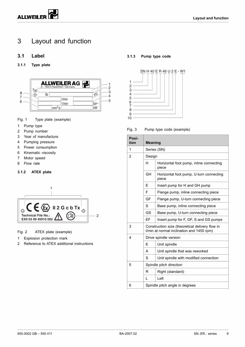
Fig. 1 Type plate (example)
1 Pump type2 Pump number3 Year of manufacture4 Pumping pressure5 Power consumption6 Kinematic viscosity7 Motor speed8 Flow rate
3.1.2 ATEX plate
Technical File No.:EX9 03 09 45910 002
II 2 G c b Tx
1
2
Fig. 2 ATEX plate (example)
1 Explosion protection mark2 Reference to ATEX additional instructions
3.1.3 Pump type code
123456
SN H 40 E R 46 U 2 E - W1
789
10
Fig. 3 Pump type code (example)
Posi-tion Meaning
1 Series (SN)
Design
H Horizontal foot pump, inline connectingpiece
GH Horizontal foot pump, U-turn connectingpiece
E Insert pump for H and GH pump
F Flange pump, inline connecting piece
GF Flange pump, U-turn connecting piece
S Base pump, inline connecting piece
GS Base pump, U-turn connecting piece
2
EF Insert pump for F, GF, S and GS pumps
3 Construction size (theoretical delivery flow inl/min at normal inclination and 1450 rpm)
Drive spindle version
E Unit spindle
A Unit spindle that was reworked
4
S Unit spindle with modified connection
Spindle pitch direction
R Right (standard)
5
L Left
6 Spindle pitch angle in degrees
650.0002 GB – 550 411 BA-2007.02 SN..ER.. series 9
Layout and function
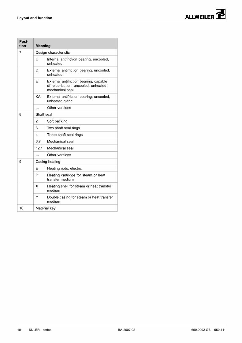
Posi-tion Meaning
Design characteristic
U Internal antifriction bearing, uncooled,unheated
D External antifriction bearing, uncooled,unheated
E External antifriction bearing, capableof relubrication; uncooled, unheatedmechanical seal
KA External antifriction bearing; uncooled,unheated gland
7
... Other versions
Shaft seal
2 Soft packing
3 Two shaft seal rings
4 Three shaft seal rings
6.7 Mechanical seal
12.1 Mechanical seal
8
... Other versions
Casing heating
E Heating rods, electric
P Heating cartridge for steam or heattransfer medium
X Heating shell for steam or heat transfermedium
9
Y Double casing for steam or heat transfermedium
10 Material key
10 SN..ER.. series BA-2007.02 650.0002 GB – 550 411
Layout and function
3.2 Layout
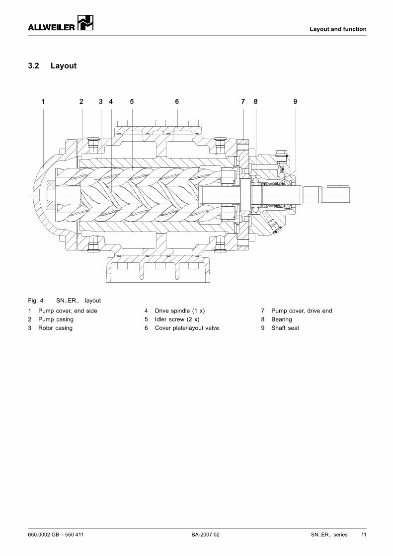
Fig. 4 SN..ER.. layout
1 Pump cover, end side2 Pump casing3 Rotor casing
4 Drive spindle (1 x)5 Idler screw (2 x)6 Cover plate/layout valve
7 Pump cover, drive end8 Bearing9 Shaft seal
650.0002 GB – 550 411 BA-2007.02 SN..ER.. series 11
Layout and function
3.3 Shaft sealsShaft seals of different design, shape and material, with orwithout additional sealing system, are available as specialversions (→ technical description).
3.3.1 Packing glandPacking glands have functional leaks.The KA2 version does not have a regulating valve andmustnot be operated in suction mode.
• Soft packing, standard version– Packing rings of Teflon-impregnated mineral fiber yarn
3.3.2 Mechanical sealsMechanical seals have functional leaks.
• Mechanical seal, standard version– Uncooled, maintenance-free unbalanced mechanical
seal construction
3.3.3 Shaft seal ringsShaft seal rings have functional leaks.
• Two or three shaft seal rings, standard version
3.4 Storage and lubricationBearings of different design, lubrication and material, withor without additional relubrication system, are available asspecial versions (→ technical description).
3.4.1 Internal antifriction bearingGroove ball bearing lubricated with pumped liquid according toDIN 625.
3.4.2 External antifriction bearing• D, KA version:
– Groove ball bearing lubricated with grease accordingto DIN 625
– Lifetime grease fill, incapable of relubrication– Sealing washers, both sides
• E version:– Groove ball bearing lubricated with grease according
to DIN 625– Can be relubricated by means of grease nipple
3.5 Sealing systemsSealing systems of various design are available as specialversions (→ technical description).
3.6 Auxiliary systems (heating)Information on heating and heating capacity (→ technicaldescription)Further information (→ VM 4.70,drawing 600 0002 024)
12 SN..ER.. series BA-2007.02 650.0002 GB – 550 411
Layout and function
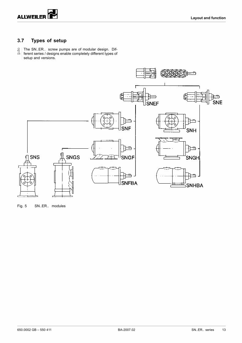
3.7 Types of setupThe SN..ER.. screw pumps are of modular design. Dif-ferent series / designs enable completely different types ofsetup and versions.
Fig. 5 SN..ER.. modules
650.0002 GB – 550 411 BA-2007.02 SN..ER.. series 13
Transport, storage and disposal
4 Transport, storage and disposal
4.1 TransportWeight specifications (→ order data sheet).
4.1.1 Unpacking and inspection on delivery1. Unpack the pump/aggregate on delivery and inspect it for
transport damage.2. Report any transport damage to the manufacturer immedi-
ately.3. Dispose of packaging material according to local regula-
tions.
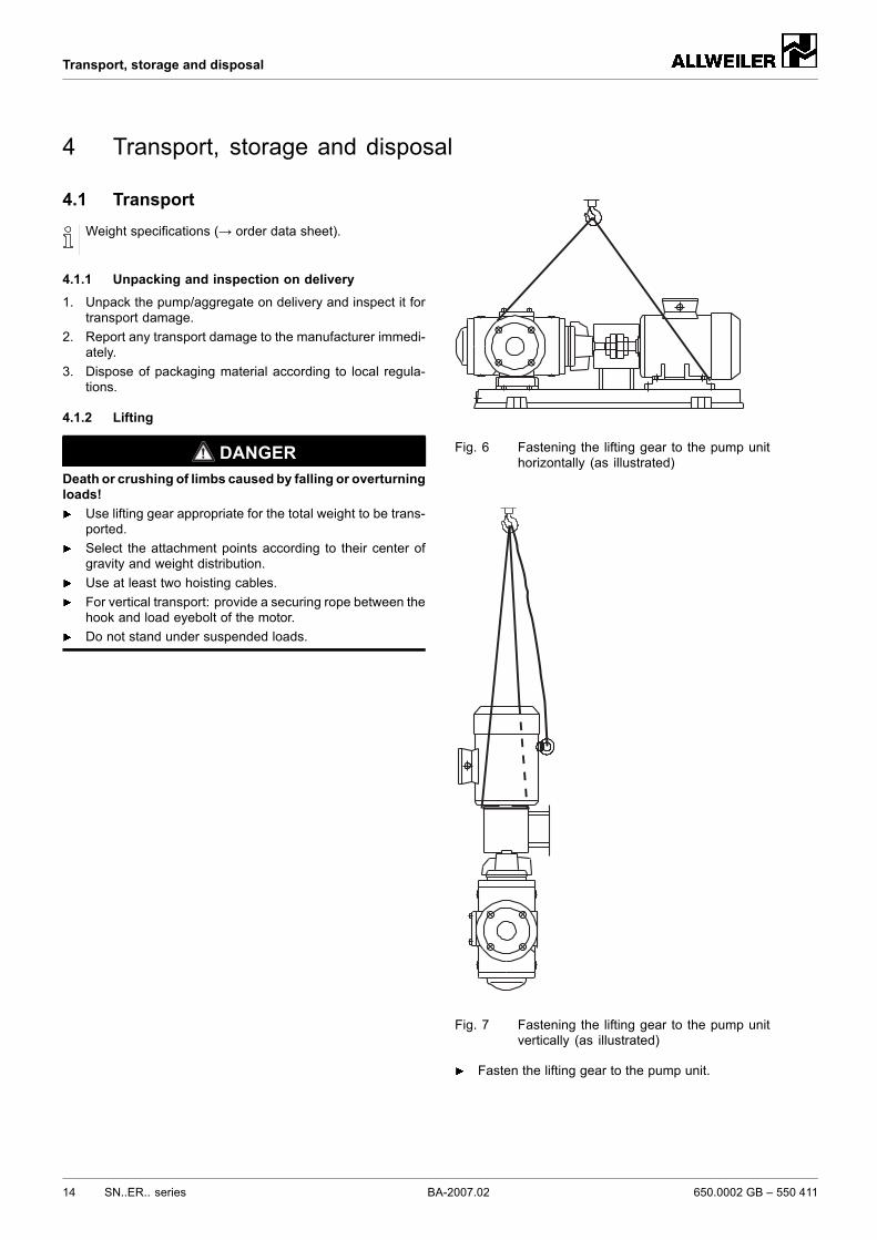
4.1.2 Lifting
DANGERDeath or crushing of limbs caused by falling or overturningloads!
Use lifting gear appropriate for the total weight to be trans-ported.Select the attachment points according to their center ofgravity and weight distribution.Use at least two hoisting cables.For vertical transport: provide a securing rope between thehook and load eyebolt of the motor.Do not stand under suspended loads.
Fig. 6 Fastening the lifting gear to the pump unithorizontally (as illustrated)
Fig. 7 Fastening the lifting gear to the pump unitvertically (as illustrated)
Fasten the lifting gear to the pump unit.
14 SN..ER.. series BA-2007.02 650.0002 GB – 550 411
Transport, storage and disposal
4.2 Treatment for storageThe pump has not been treated for storage at the factory.Preservation not necessary for non-rusting materials.
CAUTIONMaterial damage due tomissing or inappropriate treatmentfor storage!
Treat the pump properly, inside and outside, for storage.
4.2.1 Applying preservative to the inside
Spray the insert units with preservative (e.g. RUST-BAN335) and shrink-wrap them in plastic film.
1. Close the suction-side flange with a blank flange.2. With opposite flanges, turn the pump onto the suction
flange.3. Fill the pump with preservative (e.g. RUST-BAN 335).4. Turn the shaft slowly against the pump's sense of rotation.5. Continue filling and turning until preservative without bub-
bles comes out of the pressure flange.6. Close the pressure-side flange with a blank flange.7. Every 6 months:
– Renew the preservative if necessary.
4.2.2 Applying preservative to the outside1. Apply preservative to all bare metal parts.2. Every 6 months:
– Renew the preservative if necessary.
4.3 Storage
CAUTIONMaterial damage due to inappropriate storage!
Treat and store the pump properly.
1. Seal all openings with blind flanges, blind plugs or plasticcovers.
2. Make sure the storage room meets the following condi-tions:– Dry– Frost-free– Vibration-free– Dust-free
3. Turn the shaft once a month.4. Make sure the shaft and bearing change their rotational
position in the process.
4.4 Removing preservativeOnly necessary for pumps treated for storage.
CAUTIONHigh water pressure or spray water can damage bearings!
Do not clean bearing areas with a water or steam jet.
CAUTIONDamage to seals by using the wrong cleaning agents!
Ensure the cleaning agent does not corrode the seals.
1. Choose the cleaning agent according to the application.(→ 9.2.6 Cleaning agents, Page 37).
2. Remove the preservative from all bare internal parts of thepump.
3. Dispose of cleaning agents in accordance with local regu-lations.
4. For storage times in excess of 6 months:– Replace the elastomer parts made of EP rubber
(EPDM).– Check all elastomer parts (O-rings, shaft seals) for
proper elasticity and replace them if necessary.
4.5 DisposalPlastic parts can be contaminated by poisonous or radio-active pumped liquids to such an extent that cleaning willbe insufficient.
WARNINGRisk of poisoning and environmental damage by thepumped liquid or oil!
Use protective equipment when carrying out any work onthe pump.Prior to the disposal of the pump:– Collect and dispose of any escaping pumped liquid or
oil in accordance with local regulations.– Neutralize residues of pumped liquid in the pump.– Removing preservative (→ 4.4 Removing preserva-
tive, Page 15).Remove the plastic parts and dispose of them in accor-dance with local regulations.
Dispose of the pump in accordance with local regulations.
650.0002 GB – 550 411 BA-2007.02 SN..ER.. series 15
Setup and connection
5 Setup and connection
For pumps in explosion-hazard areas (→ ATEX additionalinstructions).
CAUTIONMaterial damage caused by dirt!
Do not remove any covers or transport and screw plugsuntil immediately before connecting the pipes to the pump.
5.1 Preparing the setup
5.1.1 Checking the ambient conditionsMake sure the required ambient conditions are fulfilled(→ 9.2.1 Ambient conditions, Page 36).
5.1.2 Preparing the installation siteEnsure the installation site meets the following conditions:– Pump is freely accessible from all sides– Sufficient space for the installation/removal of the pipes
and for maintenance and repair work, especially for theremoval and installation of the pump and the motor
– Pump not exposed to external vibrations (damage tobearings)
– Frost protection
5.1.3 Preparing the surfaceMake sure the surface meets the following conditions:– Level– Clean (no oil, dust or other impurities)– Capable of bearing the weight of the pump unit and all
operating forces– Ensure the pump is stable and cannot tip over
5.1.4 Removing preservativeIf the pump is to be put into operation immediately aftersetup and connection: remove the preservative prior tosetup (→ 4.4 Removing preservative, Page 15).
5.2 Setup
5.2.1 Setup with foundation
CAUTIONMaterial damage due to distortion of the base plate!
Place the base plate on the foundation and fasten it to it asdescribed in the following.
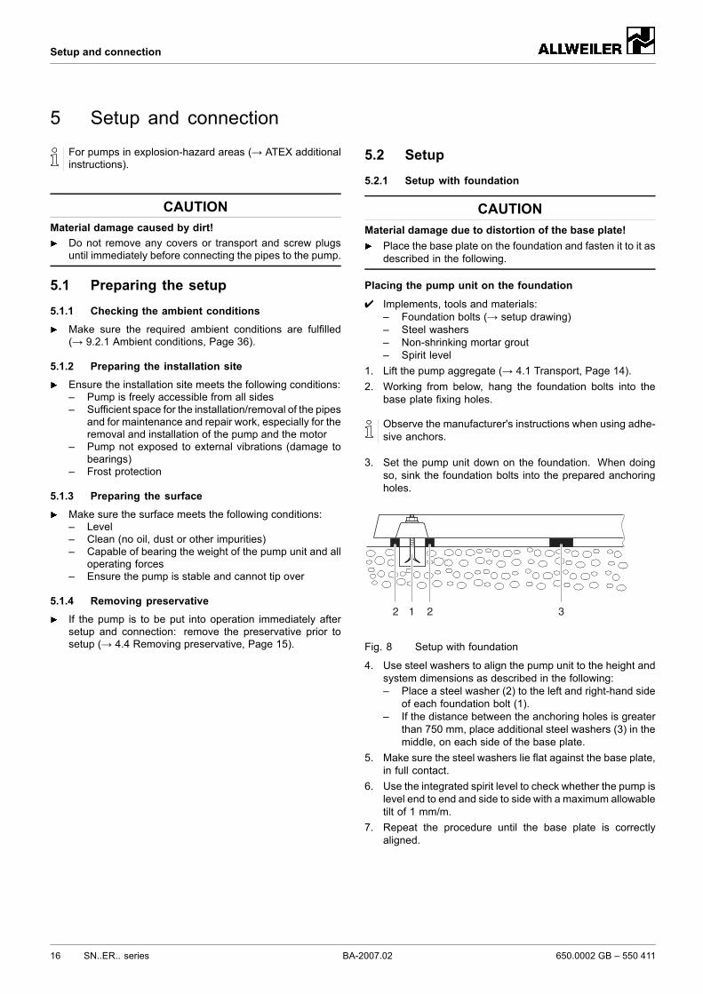
Placing the pump unit on the foundation
✔ Implements, tools and materials:– Foundation bolts (→ setup drawing)– Steel washers– Non-shrinking mortar grout– Spirit level
1. Lift the pump aggregate (→ 4.1 Transport, Page 14).2. Working from below, hang the foundation bolts into the
base plate fixing holes.
Observe the manufacturer's instructions when using adhe-sive anchors.
3. Set the pump unit down on the foundation. When doingso, sink the foundation bolts into the prepared anchoringholes.
32 1 2
Fig. 8 Setup with foundation
4. Use steel washers to align the pump unit to the height andsystem dimensions as described in the following:– Place a steel washer (2) to the left and right-hand side
of each foundation bolt (1).– If the distance between the anchoring holes is greater
than 750 mm, place additional steel washers (3) in themiddle, on each side of the base plate.
5. Make sure the steel washers lie flat against the base plate,in full contact.
6. Use the integrated spirit level to check whether the pump islevel end to end and side to side with a maximum allowabletilt of 1 mm/m.
7. Repeat the procedure until the base plate is correctlyaligned.
16 SN..ER.. series BA-2007.02 650.0002 GB – 550 411
Setup and connection
Fastening the pump unit
The damping behavior is improved by filling the base platewith mortar grout.
1. Fill the anchoring holes with mortar grout.2. When the mortar grout has set, screw down the base plate
at three points with the specified torque.3. Before tightening the remaining bolts, compensate for any
unevenness in the surface using metal spacing shims nextto each bolt.
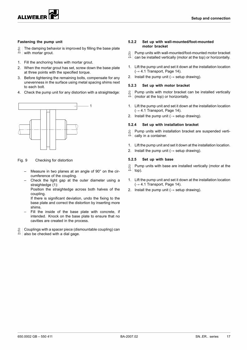
4. Check the pump unit for any distortion with a straightedge:
1
Fig. 9 Checking for distortion
– Measure in two planes at an angle of 90° on the cir-cumference of the coupling.
– Check the light gap at the outer diameter using astraightedge (1):Position the straightedge across both halves of thecoupling.If there is significant deviation, undo the fixing to thebase plate and correct the distortion by inserting moreshims.
– Fill the inside of the base plate with concrete, ifintended. Knock on the base plate to ensure that nocavities are created in the process.
Couplings with a spacer piece (dismountable coupling) canalso be checked with a dial gage.
5.2.2 Set up with wall-mounted/foot-mountedmotor bracket
Pump units with wall-mounted/foot-mounted motor bracketcan be installed vertically (motor at the top) or horizontally.
1. Lift the pump unit and set it down at the installation location(→ 4.1 Transport, Page 14).
2. Install the pump unit (→ setup drawing).
5.2.3 Set up with motor bracket
Pump units with motor bracket can be installed vertically(motor at the top) or horizontally.
1. Lift the pump unit and set it down at the installation location(→ 4.1 Transport, Page 14).
2. Install the pump unit (→ setup drawing).
5.2.4 Set up with installation bracket
Pump units with installation bracket are suspended verti-cally in a container.
1. Lift the pump unit and set it down at the installation location.2. Install the pump unit (→ setup drawing).
5.2.5 Set up with base
Pump units with base are installed vertically (motor at thetop).
1. Lift the pump unit and set it down at the installation location(→ 4.1 Transport, Page 14).
2. Install the pump unit (→ setup drawing).
650.0002 GB – 550 411 BA-2007.02 SN..ER.. series 17
Setup and connection
5.3 Installing the motor
5.3.1 Installing the motor on the base plateOnly necessary if the pump unit is assembled on site.
CAUTIONMaterial damage caused by knocks and bumps!
Keep the coupling halves properly aligned when slippingthem on.Do not knock or hit any components of the pump.
1. Smear a very thin coat of molybdenum disulfide (e.g.Molykote) on the shaft ends of the pump and motor.
2. Insert shaft keys.3. Without a mounting rig: remove the rubber buffers and heat
the coupling halves up to approximately 100 °C.4. Slide on the pump-side and motor-side coupling halves
until the shaft end is flush with the coupling hub. Whendoing so, make sure the prescribed distance between thecoupling halves is maintained (→ assembly instructions forthe coupling).
5. Tighten the grub screws on both coupling halves.6. Use suitable metal shims at the motor to align the end of
the motor shaft to the end of the pump shaft.7. Screw in the motor bolts, but do not tighten them yet
(→ 5.8 Aligning the motor, Page 21).
5.3.2 Installing the motor at pumps in flange version
Only necessary if the pump unit is assembled on site.
CAUTIONMaterial damage caused by knocks and bumps!
Keep the coupling halves properly aligned when slippingthem on.Do not knock or hit any components of the pump.
1. Smear a very thin coat of molybdenum disulfide (e.g.Molykote) on the shaft ends of the pump and motor.
2. Insert shaft keys.3. Slip on the pump-side and motor-side coupling halves in
line.– Without a mounting rig: remove the rubber buffers and
heat the coupling halves up to approximately 100 °C.4. Tighten the grub screws on both coupling halves.5. Raise the motor and position it on the bell housing.6. Check the distance between the coupling halves with a
feeler gage:– Permissible gap (→ setup drawing)– Use the feeler gage to measure the gap (A) between
the coupling halves.– Align the coupling halves if the gap is too wide.
7. Tighten the motor bolts.
5.4 Planning the pipes
5.4.1 Specifying supports and flange connections
CAUTIONMaterial damage due to excessive forces and torquesexerted by the piping on the pump!
Do not exceed the permissible values (→ flange loadsaccording to EN ISO 14847)
1. Calculate the pipe forces, taking every possible operatingcondition into account:– Cold/warm– Empty/full– Unpressurized/pressurized– Positional changes of the flanges
2. Ensure the pipe supports have permanent low-frictionproperties and do not seize up due to corrosion.
5.4.2 Specifying nominal diameters
Keep the flow resistance in the pipes as low as possible.
1. Make sure the nominal suction pipe diameter is not smallerthan the nominal suction branch diameter.– Make sure the flow rate is below 1 m/s
2. Make sure the nominal pressure pipe diameter is notsmaller than the nominal outlet flange diameter.– Make sure the flow rate is below 3 m/s
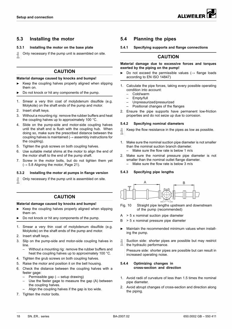
5.4.3 Specifying pipe lengths
BA
Fig. 10 Straight pipe lengths upstream and downstreamof the pump (recommended)
A > 5 x nominal suction pipe diameterB > 5 x nominal pressure pipe diameter
Maintain the recommended minimum values when install-ing the pump.
Suction side: shorter pipes are possible but may restrictthe hydraulic performance.Pressure side: shorter pipes are possible but can result inincreased operating noise.
5.4.4 Optimizing changes incross-section and direction
1. Avoid radii of curvature of less than 1.5 times the nominalpipe diameter.
2. Avoid abrupt changes of cross-section and direction alongthe piping.
18 SN..ER.. series BA-2007.02 650.0002 GB – 550 411
Setup and connection
5.4.5 Avoiding excessive pressure
WARNINGRisk of injury due to excessive pressure!
If no pressure relief valve is present: provide an appropri-ate safety valve in the pressure line.
CAUTIONMaterial damage due to overheating of the pump!
If the return flow of the pressure relief valve flows directlyinto the pump suction side or suction line: monitor the tem-perature.
1. Observe the operating instructions of the manufacturer.2. Make sure the factory setting of the pressure relief valve
meets the requirements of the system.3. Do not feed the return flow of the safety valve directly back
into the suction pipe.
5.4.6 Providing safety and control devices(recommended)
Avoid impurities
1. Install a dirt trap in the suction pipe (mesh size of 0.6 mm).2. To monitor impurities, install a differential pressure gauge
with contact manometer.3. Provide a fine filter if necessary:
– Select the filter mesh, depending on the type, level ofdirt and pumping pressure
Make provisions for isolating and shutting off the pipes
For maintenance and repair work.
Provide shut-off devices in the suction and pressure pipes.
Allow measurements of the operating conditions
1. Provide manometers for pressure measurements in thesuction and pressure pipes.
2. Provide for suction-side temperature measurements.
5.5 Connecting the pipes
5.5.1 Keeping the piping clean
CAUTIONMaterial damage due to impurities in the pump!
Make sure no impurities can enter the pump.
1. Flush all piping parts and fittings prior to assembly.2. Ensure no flange seals protrude inwards.3. Remove any blank flanges, plugs, protective foils and/or
protective paint from the flanges.4. Remove any welding beads from welded pipes.
5.5.2 Installing the suction pipe
1. Remove the transport and screw plugs from the pump.2. To avoid air pockets:
– For supply operation: run the pipes with a continuousdownward slope to the pump.
3. Ensure no seals protrude inwards.4. With wet pit installations: observe the minimum immersion
depth (→ technical description).
5.5.3 Installing the pressure pipe
1. Remove the transport and screw plugs from the pump.2. Install the pressure pipe.3. Ensure no seals protrude inwards.
5.5.4 Inspection for stress-free pipe connections✔ Piping installed and cooled down1. Disconnect the pipe connecting flanges from the pump.2. Check whether the pipes can be moved freely in all direc-
tions within the expected range of expansion:– Nominal diameter < 150 mm: by hand– Nominal diameter > 150 mm: with a small lever
3. Make sure the flange surfaces are parallel.4. Reconnect the pipe connecting flanges to the pump.
650.0002 GB – 550 411 BA-2007.02 SN..ER.. series 19
Setup and connection
5.6 Electrical connection
DANGERRisk of death due to electric shock!
Have all electrical work carried out by qualified electriciansonly.
5.6.1 Connecting the motorFollow the instructions of the motor manufacturer.
1. Connect the motor according to the connection diagram.2. Make sure no danger arises due to electric power.3. Install an EMERGENCY STOP switch.
5.7 Aligning the coupling preciselyNot necessary with flanged drives
DANGERRisk of death due to rotating parts!
Isolate the motor from its supply voltage and keep it lockedin that state when carrying out any fitting or maintenancework.
CAUTIONMaterial damage due to incorrect alignment of the cou-pling!
Align the motor exactly to the pump if there is any vertical,lateral or angular misalignment.For detailed information and special couplings: (→ manu-facturer's specifications)
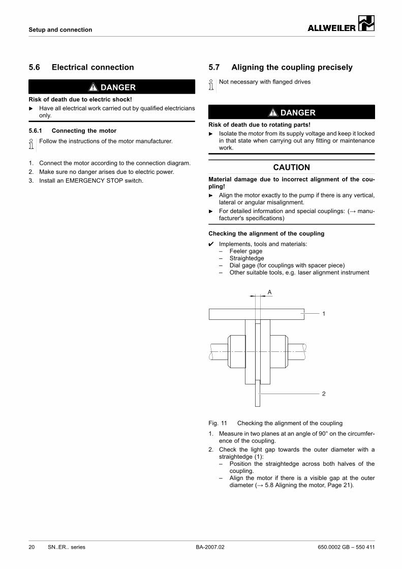
Checking the alignment of the coupling✔ Implements, tools and materials:
– Feeler gage– Straightedge– Dial gage (for couplings with spacer piece)– Other suitable tools, e.g. laser alignment instrument
1
2
A
Fig. 11 Checking the alignment of the coupling
1. Measure in two planes at an angle of 90° on the circumfer-ence of the coupling.
2. Check the light gap towards the outer diameter with astraightedge (1):– Position the straightedge across both halves of the
coupling.– Align the motor if there is a visible gap at the outer
diameter (→ 5.8 Aligning the motor, Page 21).
20 SN..ER.. series BA-2007.02 650.0002 GB – 550 411
Setup and connection
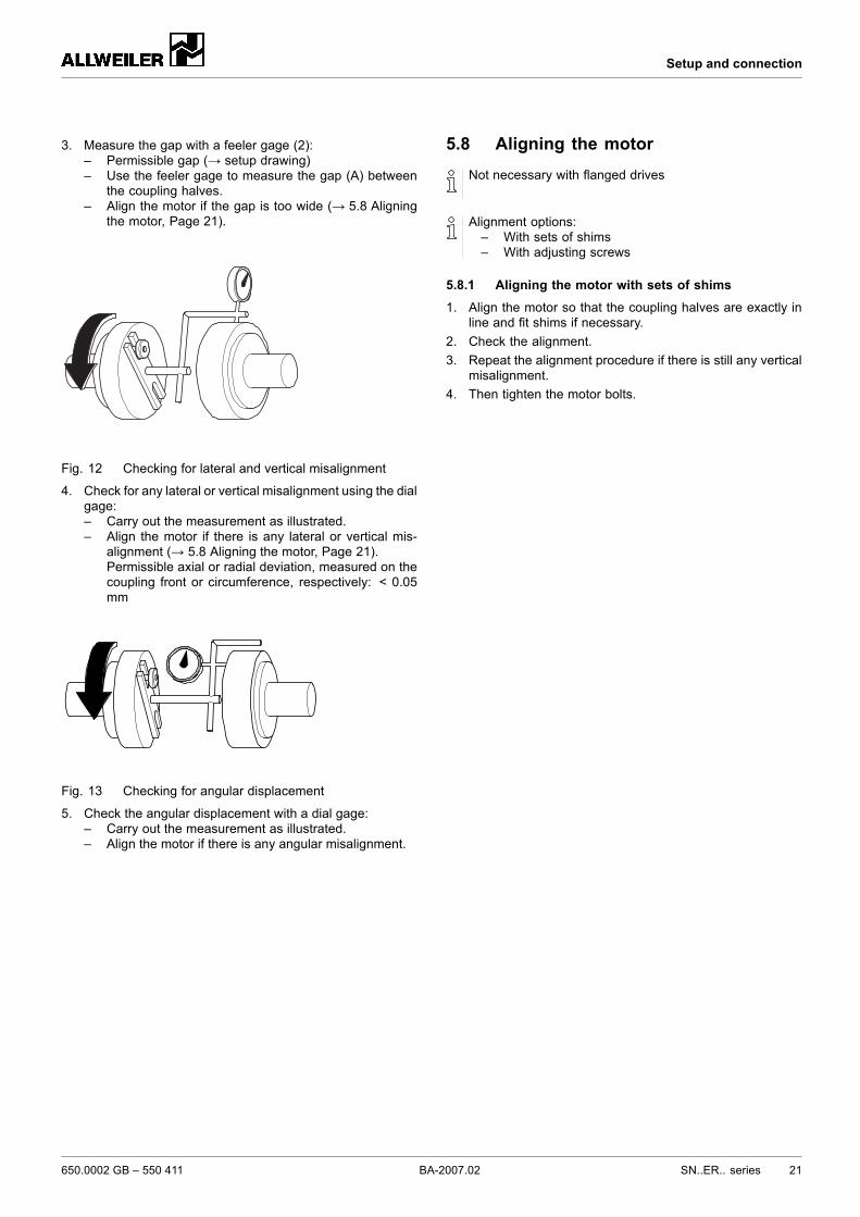
3. Measure the gap with a feeler gage (2):– Permissible gap (→ setup drawing)– Use the feeler gage to measure the gap (A) between
the coupling halves.– Align the motor if the gap is too wide (→ 5.8 Aligning
the motor, Page 21).
Fig. 12 Checking for lateral and vertical misalignment
4. Check for any lateral or vertical misalignment using the dialgage:– Carry out the measurement as illustrated.– Align the motor if there is any lateral or vertical mis-
alignment (→ 5.8 Aligning the motor, Page 21).Permissible axial or radial deviation, measured on thecoupling front or circumference, respectively: < 0.05mm
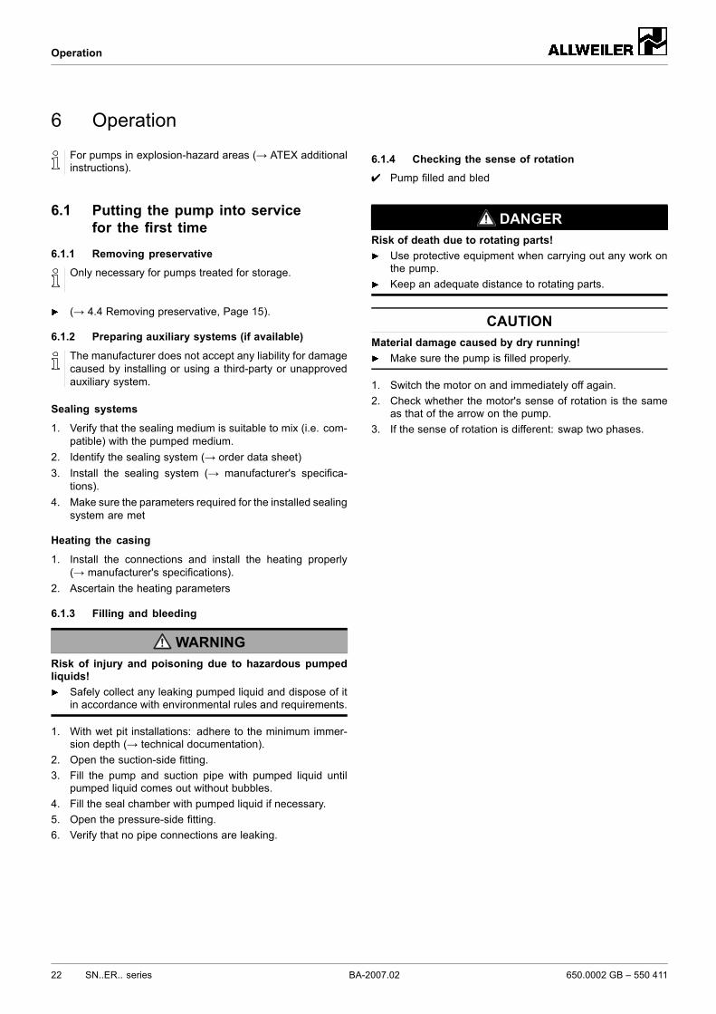
Fig. 13 Checking for angular displacement
5. Check the angular displacement with a dial gage:– Carry out the measurement as illustrated.– Align the motor if there is any angular misalignment.
5.8 Aligning the motorNot necessary with flanged drives
Alignment options:– With sets of shims– With adjusting screws
5.8.1 Aligning the motor with sets of shims1. Align the motor so that the coupling halves are exactly in
line and fit shims if necessary.2. Check the alignment.3. Repeat the alignment procedure if there is still any vertical
misalignment.4. Then tighten the motor bolts.
650.0002 GB – 550 411 BA-2007.02 SN..ER.. series 21
Operation
6 Operation
For pumps in explosion-hazard areas (→ ATEX additionalinstructions).
6.1 Putting the pump into servicefor the first time
6.1.1 Removing preservative
Only necessary for pumps treated for storage.
(→ 4.4 Removing preservative, Page 15).
6.1.2 Preparing auxiliary systems (if available)
The manufacturer does not accept any liability for damagecaused by installing or using a third-party or unapprovedauxiliary system.
Sealing systems
1. Verify that the sealing medium is suitable to mix (i.e. com-patible) with the pumped medium.
2. Identify the sealing system (→ order data sheet)3. Install the sealing system (→ manufacturer's specifica-
tions).4. Make sure the parameters required for the installed sealing
system are met
Heating the casing
1. Install the connections and install the heating properly(→ manufacturer's specifications).
2. Ascertain the heating parameters
6.1.3 Filling and bleeding
WARNINGRisk of injury and poisoning due to hazardous pumpedliquids!
Safely collect any leaking pumped liquid and dispose of itin accordance with environmental rules and requirements.
1. With wet pit installations: adhere to the minimum immer-sion depth (→ technical documentation).
2. Open the suction-side fitting.3. Fill the pump and suction pipe with pumped liquid until
pumped liquid comes out without bubbles.4. Fill the seal chamber with pumped liquid if necessary.5. Open the pressure-side fitting.6. Verify that no pipe connections are leaking.
6.1.4 Checking the sense of rotation✔ Pump filled and bled
DANGERRisk of death due to rotating parts!
Use protective equipment when carrying out any work onthe pump.Keep an adequate distance to rotating parts.
CAUTIONMaterial damage caused by dry running!
Make sure the pump is filled properly.
1. Switch the motor on and immediately off again.2. Check whether the motor's sense of rotation is the same
as that of the arrow on the pump.3. If the sense of rotation is different: swap two phases.
22 SN..ER.. series BA-2007.02 650.0002 GB – 550 411
Operation
6.1.5 Switching on
✔ Pump set up and connected properly✔ Motor set up and connected properly✔ All connections stress-free and sealed✔ All safety equipment installed and tested for functionality✔ Pump prepared, filled and bled properly✔ Sufficient filling level in the container
DANGERRisk of injury due to running pump!
Do not touch the running pump.Do not carry out any work on the running pump.Allow the pump to cool down completely before starting anywork.
DANGERRisk of injury and poisoning due to pumped liquid spray-ing out!
Use protective equipment when carrying out any work onthe pump.
CAUTIONRisk of cavitation when throttling down the suction flowrate!
Fully open the suction-side fitting and do not use it to adjustthe flow.
CAUTIONMaterial damage due to excessive pressure!
Do not operate the pump while the pressure-side fitting isclosed.
CAUTIONMaterial damage caused by dry running!
Make sure the pump is filled properly.
1. Open the pressure-side fitting.2. Open the suction-side fitting.3. Switch on the motor and check it for smooth running.4. Make sure the temperature rises at a rate of no more than
2 K/min.5. Make sure the minimum pumping pressure is above 2 bar.6. After the first load under pressure and at operating temper-
ature, check that the pump is not leaking.
6.1.6 Switching off
WARNINGRisk of injury due to hot pump parts!
Use protective equipment when carrying out any work onthe pump.
1. Switch off the motor.2. Check all tie bolts and retighten them if necessary after
putting the pump into service for the first time.
6.2 Operating
6.2.1 Switching on✔ Pump initially put into service properly✔ Pumps filled and bled
DANGERRisk of injury due to running pump!
Do not touch the running pump.Do not carry out any work on the running pump.Allow the pump to cool down completely before starting anywork.
DANGERRisk of injury and poisoning due to pumped liquid spray-ing out!
Use protective equipment when carrying out any work onthe pump.
CAUTIONRisk of cavitation when throttling down the suction flowrate!
Fully open the suction-side fitting and do not use it to adjustthe flow.
CAUTIONMaterial damage caused by dry running!
Make sure the pump is filled properly.
1. Open the pressure-side fitting.2. Open the suction-side fitting.3. Switch on the motor and check it for smooth running.4. Make sure the temperature rises at a rate of no more than
2 K/min.5. Make sure the minimum pumping pressure is above 2 bar.6. If present, set a slight leak at the packing gland.
6.2.3 Switching offSwitch off the motor.
650.0002 GB – 550 411 BA-2007.02 SN..ER.. series 23
Operation
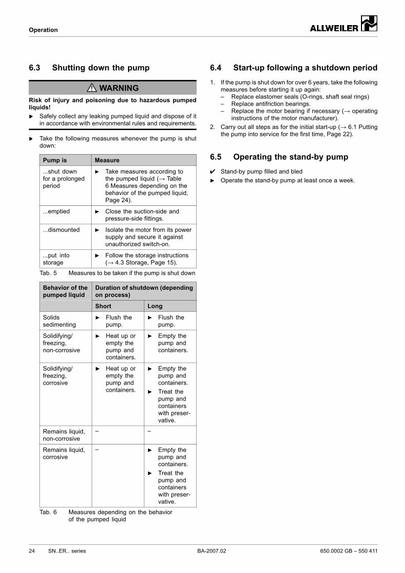
6.3 Shutting down the pump
WARNINGRisk of injury and poisoning due to hazardous pumpedliquids!
Safely collect any leaking pumped liquid and dispose of itin accordance with environmental rules and requirements.
Take the following measures whenever the pump is shutdown:
Pump is Measure
...shut downfor a prolongedperiod
Take measures according tothe pumped liquid (→ Table6 Measures depending on thebehavior of the pumped liquid,Page 24).
...emptied Close the suction-side andpressure-side fittings.
...dismounted Isolate the motor from its powersupply and secure it againstunauthorized switch-on.
...put intostorage
Follow the storage instructions(→ 4.3 Storage, Page 15).
Tab. 5 Measures to be taken if the pump is shut down
Duration of shutdown (dependingon process)
Behavior of thepumped liquid
Short Long
Solidssedimenting
Flush thepump.
Flush thepump.
Solidifying/freezing,non-corrosive
Heat up orempty thepump andcontainers.
Empty thepump andcontainers.
Solidifying/freezing,corrosive
Heat up orempty thepump andcontainers.
Empty thepump andcontainers.Treat thepump andcontainerswith preser-vative.
Remains liquid,non-corrosive
– –
Remains liquid,corrosive
– Empty thepump andcontainers.Treat thepump andcontainerswith preser-vative.
Tab. 6 Measures depending on the behaviorof the pumped liquid
6.4 Start-up following a shutdown period1. If the pump is shut down for over 6 years, take the following
measures before starting it up again:– Replace elastomer seals (O-rings, shaft seal rings)– Replace antifriction bearings.– Replace the motor bearing if necessary (→ operating
instructions of the motor manufacturer).2. Carry out all steps as for the initial start-up (→ 6.1 Putting
the pump into service for the first time, Page 22).
6.5 Operating the stand-by pump✔ Stand-by pump filled and bled
Operate the stand-by pump at least once a week.
24 SN..ER.. series BA-2007.02 650.0002 GB – 550 411
Maintenance
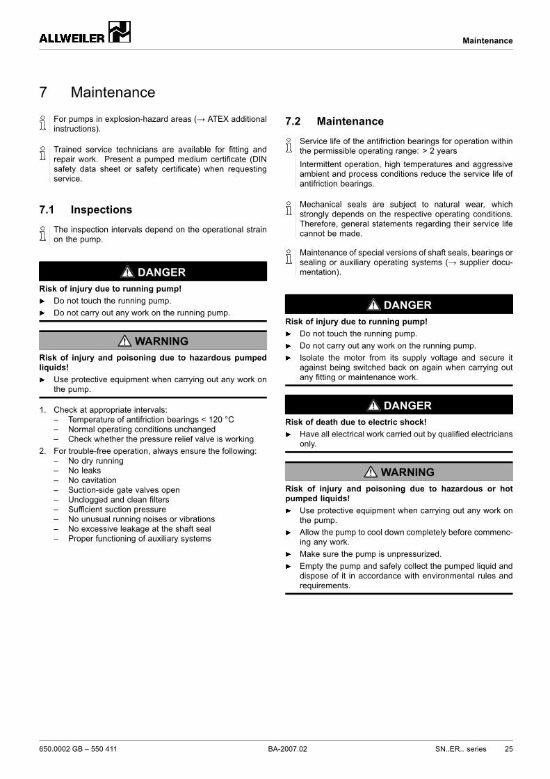
7 Maintenance
For pumps in explosion-hazard areas (→ ATEX additionalinstructions).
Trained service technicians are available for fitting andrepair work. Present a pumped medium certificate (DINsafety data sheet or safety certificate) when requestingservice.
7.1 InspectionsThe inspection intervals depend on the operational strainon the pump.
DANGERRisk of injury due to running pump!
Do not touch the running pump.Do not carry out any work on the running pump.
WARNINGRisk of injury and poisoning due to hazardous pumpedliquids!
Use protective equipment when carrying out any work onthe pump.
1. Check at appropriate intervals:– Temperature of antifriction bearings < 120 °C– Normal operating conditions unchanged– Check whether the pressure relief valve is working
2. For trouble-free operation, always ensure the following:– No dry running– No leaks– No cavitation– Suction-side gate valves open– Unclogged and clean filters– Sufficient suction pressure– No unusual running noises or vibrations– No excessive leakage at the shaft seal– Proper functioning of auxiliary systems
7.2 MaintenanceService life of the antifriction bearings for operation withinthe permissible operating range: > 2 yearsIntermittent operation, high temperatures and aggressiveambient and process conditions reduce the service life ofantifriction bearings.
Mechanical seals are subject to natural wear, whichstrongly depends on the respective operating conditions.Therefore, general statements regarding their service lifecannot be made.
Maintenance of special versions of shaft seals, bearings orsealing or auxiliary operating systems (→ supplier docu-mentation).
DANGERRisk of injury due to running pump!
Do not touch the running pump.Do not carry out any work on the running pump.Isolate the motor from its supply voltage and secure itagainst being switched back on again when carrying outany fitting or maintenance work.
DANGERRisk of death due to electric shock!
Have all electrical work carried out by qualified electriciansonly.
WARNINGRisk of injury and poisoning due to hazardous or hotpumped liquids!
Use protective equipment when carrying out any work onthe pump.Allow the pump to cool down completely before commenc-ing any work.Make sure the pump is unpressurized.Empty the pump and safely collect the pumped liquid anddispose of it in accordance with environmental rules andrequirements.
650.0002 GB – 550 411 BA-2007.02 SN..ER.. series 25
Maintenance
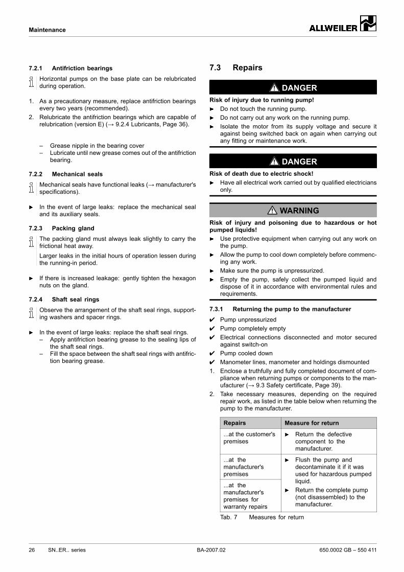
7.2.1 Antifriction bearingsHorizontal pumps on the base plate can be relubricatedduring operation.
1. As a precautionary measure, replace antifriction bearingsevery two years (recommended).
2. Relubricate the antifriction bearings which are capable ofrelubrication (version E) (→ 9.2.4 Lubricants, Page 36).
– Grease nipple in the bearing cover– Lubricate until new grease comes out of the antifriction
bearing.
7.2.2 Mechanical sealsMechanical seals have functional leaks (→ manufacturer'sspecifications).
In the event of large leaks: replace the mechanical sealand its auxiliary seals.
7.2.3 Packing glandThe packing gland must always leak slightly to carry thefrictional heat away.Larger leaks in the initial hours of operation lessen duringthe running-in period.
If there is increased leakage: gently tighten the hexagonnuts on the gland.
7.2.4 Shaft seal rings
Observe the arrangement of the shaft seal rings, support-ing washers and spacer rings.
In the event of large leaks: replace the shaft seal rings.– Apply antifriction bearing grease to the sealing lips of
the shaft seal rings.– Fill the space between the shaft seal rings with antifric-
tion bearing grease.
7.3 Repairs
DANGERRisk of injury due to running pump!
Do not touch the running pump.Do not carry out any work on the running pump.Isolate the motor from its supply voltage and secure itagainst being switched back on again when carrying outany fitting or maintenance work.
DANGERRisk of death due to electric shock!
Have all electrical work carried out by qualified electriciansonly.
WARNINGRisk of injury and poisoning due to hazardous or hotpumped liquids!
Use protective equipment when carrying out any work onthe pump.Allow the pump to cool down completely before commenc-ing any work.Make sure the pump is unpressurized.Empty the pump, safely collect the pumped liquid anddispose of it in accordance with environmental rules andrequirements.
7.3.1 Returning the pump to the manufacturer✔ Pump unpressurized✔ Pump completely empty✔ Electrical connections disconnected and motor secured
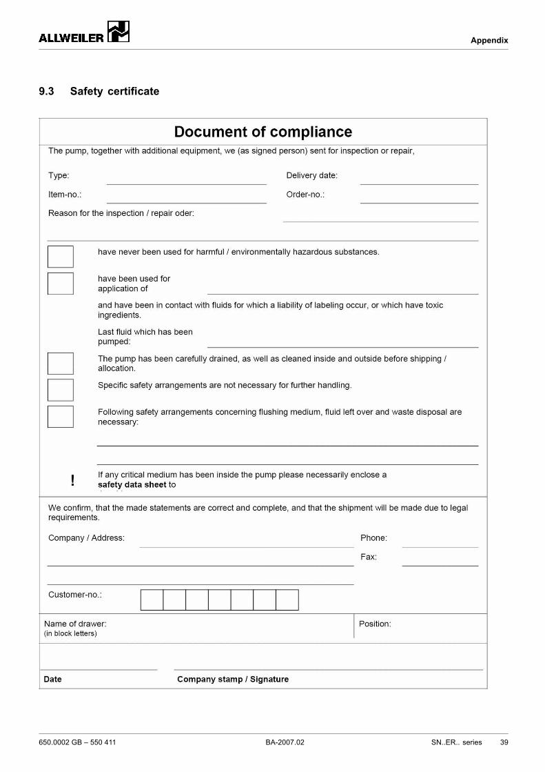
against switch-on✔ Pump cooled down✔ Manometer lines, manometer and holdings dismounted1. Enclose a truthfully and fully completed document of com-
pliance when returning pumps or components to the man-ufacturer (→ 9.3 Safety certificate, Page 39).
2. Take necessary measures, depending on the requiredrepair work, as listed in the table below when returning thepump to the manufacturer.
Repairs Measure for return
...at the customer'spremises
Return the defectivecomponent to themanufacturer.
...at themanufacturer'spremises
...at themanufacturer'spremises forwarranty repairs
Flush the pump anddecontaminate it if it wasused for hazardous pumpedliquid.Return the complete pump(not disassembled) to themanufacturer.
Tab. 7 Measures for return
26 SN..ER.. series BA-2007.02 650.0002 GB – 550 411
Maintenance
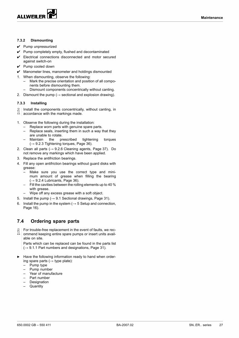
7.3.2 Dismounting
✔ Pump unpressurized✔ Pump completely empty, flushed and decontaminated✔ Electrical connections disconnected and motor secured
against switch-on✔ Pump cooled down✔ Manometer lines, manometer and holdings dismounted1. When dismounting, observe the following:
– Mark the precise orientation and position of all compo-nents before dismounting them.
– Dismount components concentrically without canting.2. Dismount the pump (→ sectional and explosion drawing).
7.3.3 Installing
Install the components concentrically, without canting, inaccordance with the markings made.
1. Observe the following during the installation:– Replace worn parts with genuine spare parts.– Replace seals, inserting them in such a way that they
are unable to rotate.– Maintain the prescribed tightening torques
(→ 9.2.3 Tightening torques, Page 36).2. Clean all parts (→ 9.2.6 Cleaning agents, Page 37). Do
not remove any markings which have been applied.3. Replace the antifriction bearings.4. Fill any open antifriction bearings without guard disks with
grease:– Make sure you use the correct type and mini-
mum amount of grease when filling the bearing(→ 9.2.4 Lubricants, Page 36).
– Fill the cavities between the rolling elements up to 40%with grease.
– Wipe off any excess grease with a soft object.5. Install the pump (→ 9.1 Sectional drawings, Page 31).6. Install the pump in the system (→ 5 Setup and connection,
Page 16).
7.4 Ordering spare partsFor trouble-free replacement in the event of faults, we rec-ommend keeping entire spare pumps or insert units avail-able on site.Parts which can be replaced can be found in the parts list(→ 9.1.1 Part numbers and designations, Page 31).
Have the following information ready to hand when order-ing spare parts (→ type plate):– Pump type– Pump number– Year of manufacture– Part number– Designation– Quantity
650.0002 GB – 550 411 BA-2007.02 SN..ER.. series 27
Troubleshooting
8 Troubleshooting
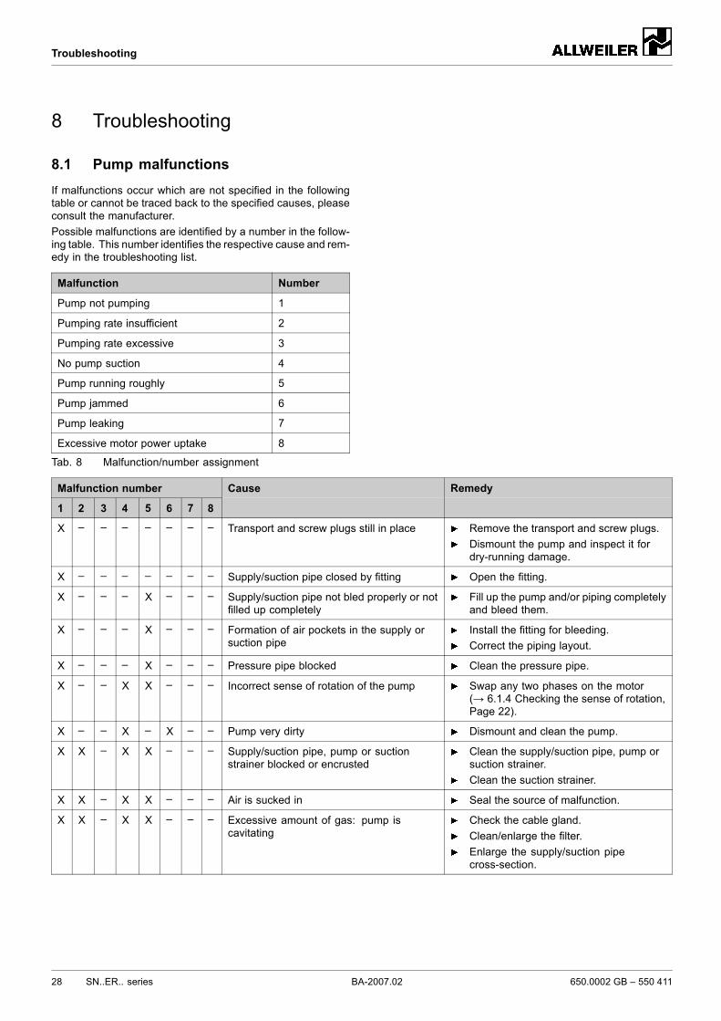
8.1 Pump malfunctionsIf malfunctions occur which are not specified in the followingtable or cannot be traced back to the specified causes, pleaseconsult the manufacturer.Possible malfunctions are identified by a number in the follow-ing table. This number identifies the respective cause and rem-edy in the troubleshooting list.
Malfunction Number
Pump not pumping 1
Pumping rate insufficient 2
Pumping rate excessive 3
No pump suction 4
Pump running roughly 5
Pump jammed 6
Pump leaking 7
Excessive motor power uptake 8
Tab. 8 Malfunction/number assignment
Malfunction number
1 2 3 4 5 6 7 8
Cause Remedy
X – – – – – – – Transport and screw plugs still in place Remove the transport and screw plugs.Dismount the pump and inspect it fordry-running damage.
X – – – – – – – Supply/suction pipe closed by fitting Open the fitting.
X – – – X – – – Supply/suction pipe not bled properly or notfilled up completely
Fill up the pump and/or piping completelyand bleed them.
X – – – X – – – Formation of air pockets in the supply orsuction pipe
Install the fitting for bleeding.Correct the piping layout.
X – – – X – – – Pressure pipe blocked Clean the pressure pipe.
X – – X X – – – Incorrect sense of rotation of the pump Swap any two phases on the motor(→ 6.1.4 Checking the sense of rotation,Page 22).
X – – X – X – – Pump very dirty Dismount and clean the pump.
X X – X X – – – Supply/suction pipe, pump or suctionstrainer blocked or encrusted
Clean the supply/suction pipe, pump orsuction strainer.Clean the suction strainer.
X X – X X – – – Air is sucked in Seal the source of malfunction.
X X – X X – – – Excessive amount of gas: pump iscavitating
Check the cable gland.Clean/enlarge the filter.Enlarge the supply/suction pipecross-section.
28 SN..ER.. series BA-2007.02 650.0002 GB – 550 411
Troubleshooting
Malfunction number
1 2 3 4 5 6 7 8
Cause Remedy
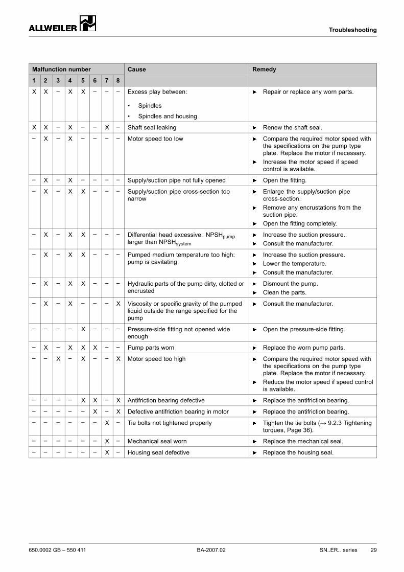
X X – X X – – – Excess play between:
• Spindles
• Spindles and housing
Repair or replace any worn parts.
X X – X – – X – Shaft seal leaking Renew the shaft seal.
– X – X – – – – Motor speed too low Compare the required motor speed withthe specifications on the pump typeplate. Replace the motor if necessary.Increase the motor speed if speedcontrol is available.
– X – X – – – – Supply/suction pipe not fully opened Open the fitting.
– X – X X – – – Supply/suction pipe cross-section toonarrow
Enlarge the supply/suction pipecross-section.Remove any encrustations from thesuction pipe.Open the fitting completely.
– X – X X – – – Differential head excessive: NPSHpumplarger than NPSHsystem
Increase the suction pressure.Consult the manufacturer.
– X – X X – – – Pumped medium temperature too high:pump is cavitating
Increase the suction pressure.Lower the temperature.Consult the manufacturer.
– X – X X – – – Hydraulic parts of the pump dirty, clotted orencrusted
Dismount the pump.Clean the parts.
– X – X – – – X Viscosity or specific gravity of the pumpedliquid outside the range specified for thepump
Consult the manufacturer.
– – – – X – – – Pressure-side fitting not opened wideenough
Open the pressure-side fitting.
– X – X X X – – Pump parts worn Replace the worn pump parts.
– – X – X – – X Motor speed too high Compare the required motor speed withthe specifications on the pump typeplate. Replace the motor if necessary.Reduce the motor speed if speed controlis available.
– – – – X X – X Antifriction bearing defective Replace the antifriction bearing.
– – – – – X – X Defective antifriction bearing in motor Replace the antifriction bearing.
– – – – – – X – Tie bolts not tightened properly Tighten the tie bolts (→ 9.2.3 Tighteningtorques, Page 36).
– – – – – – X – Mechanical seal worn Replace the mechanical seal.
– – – – – – X – Housing seal defective Replace the housing seal.
650.0002 GB – 550 411 BA-2007.02 SN..ER.. series 29
Troubleshooting
Malfunction number
1 2 3 4 5 6 7 8
Cause Remedy
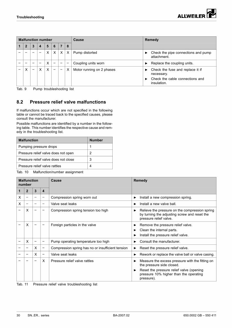
– – – – X X X X Pump distorted Check the pipe connections and pumpattachment.
– – – – X – – – Coupling units worn Replace the coupling units.
– X – X X – – X Motor running on 2 phases Check the fuse and replace it ifnecessary.Check the cable connections andinsulation.
Tab. 9 Pump troubleshooting list
8.2 Pressure relief valve malfunctionsIf malfunctions occur which are not specified in the followingtable or cannot be traced back to the specified causes, pleaseconsult the manufacturer.Possible malfunctions are identified by a number in the follow-ing table. This number identifies the respective cause and rem-edy in the troubleshooting list.
Malfunction Number
Pumping pressure drops 1
Pressure relief valve does not open 2
Pressure relief valve does not close 3
Pressure relief valve rattles 4
Tab. 10 Malfunction/number assignment
Malfunctionnumber
1 2 3 4
Cause Remedy
X – – – Compression spring worn out Install a new compression spring.
X – – – Valve seat leaks Install a new valve ball.
– X – – Compression spring tension too high Relieve the pressure on the compression springby turning the adjusting screw and reset thepressure relief valve.
– X – – Foreign particles in the valve Remove the pressure relief valve.Clean the internal parts.Install the pressure relief valve.
– X – – Pump operating temperature too high Consult the manufacturer.
– – X – Compression spring has no or insufficient tension Reset the pressure relief valve.
– – X – Valve seat leaks Rework or replace the valve ball or valve casing.
– – – X Pressure relief valve rattles Measure the excess pressure with the fitting onthe pressure side closed.Reset the pressure relief valve (openingpressure 10% higher than the operatingpressure).
Tab. 11 Pressure relief valve troubleshooting list
30 SN..ER.. series BA-2007.02 650.0002 GB – 550 411
Appendix
9 Appendix
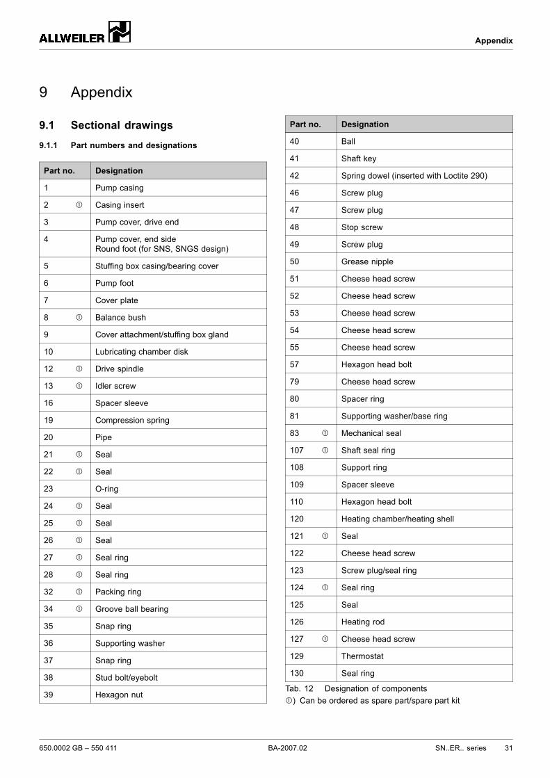
9.1 Sectional drawings
9.1.1 Part numbers and designations
Part no. Designation
1 Pump casing
2 Casing insert
3 Pump cover, drive end
4 Pump cover, end sideRound foot (for SNS, SNGS design)
5 Stuffing box casing/bearing cover
6 Pump foot
7 Cover plate
8 Balance bush
9 Cover attachment/stuffing box gland
10 Lubricating chamber disk
12 Drive spindle
13 Idler screw
16 Spacer sleeve
19 Compression spring
20 Pipe
21 Seal
22 Seal
23 O-ring
24 Seal
25 Seal
26 Seal
27 Seal ring
28 Seal ring
32 Packing ring
34 Groove ball bearing
35 Snap ring
36 Supporting washer
37 Snap ring
38 Stud bolt/eyebolt
39 Hexagon nut
Part no. Designation
40 Ball
41 Shaft key
42 Spring dowel (inserted with Loctite 290)
46 Screw plug
47 Screw plug
48 Stop screw
49 Screw plug
50 Grease nipple
51 Cheese head screw
52 Cheese head screw
53 Cheese head screw
54 Cheese head screw
55 Cheese head screw
57 Hexagon head bolt
79 Cheese head screw
80 Spacer ring
81 Supporting washer/base ring
83 Mechanical seal
107 Shaft seal ring
108 Support ring
109 Spacer sleeve
110 Hexagon head bolt
120 Heating chamber/heating shell
121 Seal
122 Cheese head screw
123 Screw plug/seal ring
124 Seal ring
125 Seal
126 Heating rod
127 Cheese head screw
129 Thermostat
130 Seal ring
Tab. 12 Designation of components) Can be ordered as spare part/spare part kit
650.0002 GB – 550 411 BA-2007.02 SN..ER.. series 31
Appendix
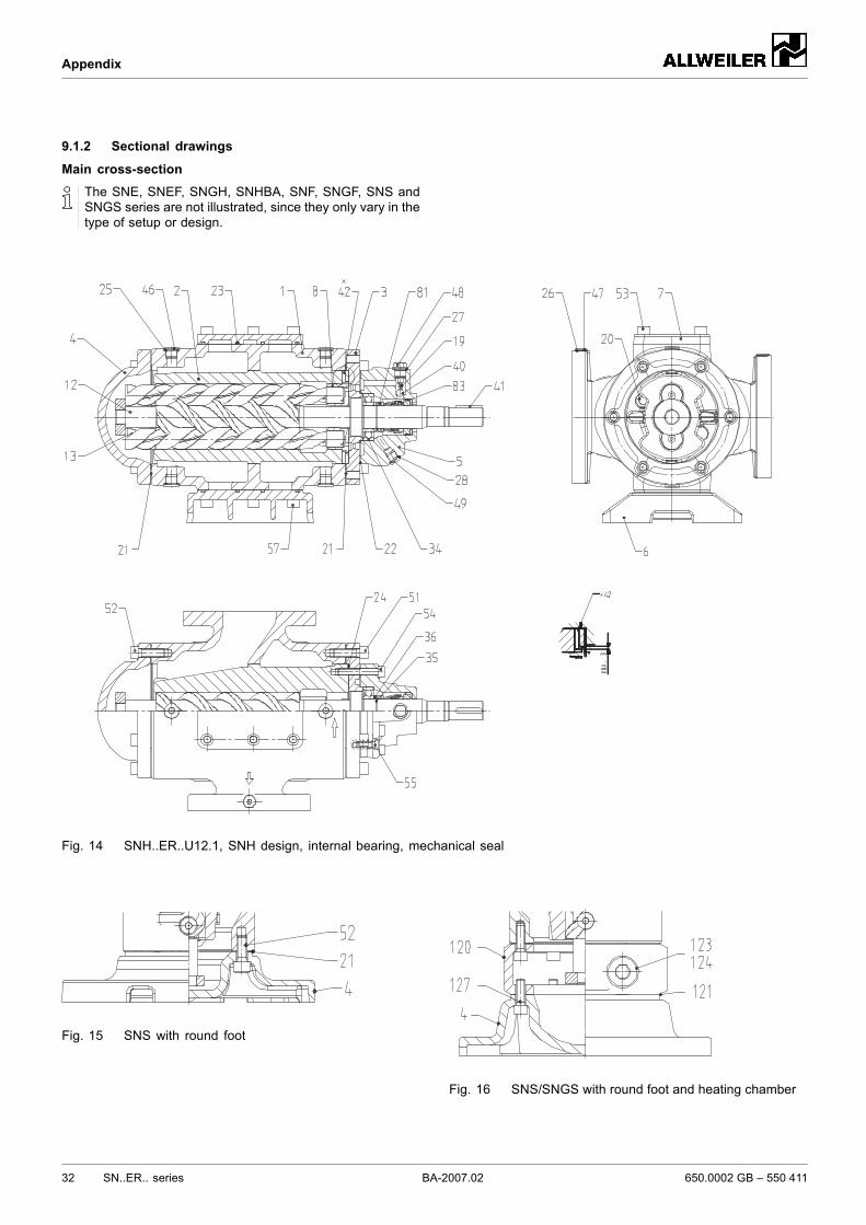
9.1.2 Sectional drawings
Main cross-section
The SNE, SNEF, SNGH, SNHBA, SNF, SNGF, SNS andSNGS series are not illustrated, since they only vary in thetype of setup or design.
Fig. 14 SNH..ER..U12.1, SNH design, internal bearing, mechanical seal
Fig. 15 SNS with round foot
Fig. 16 SNS/SNGS with round foot and heating chamber
32 SN..ER.. series BA-2007.02 650.0002 GB – 550 411
Appendix
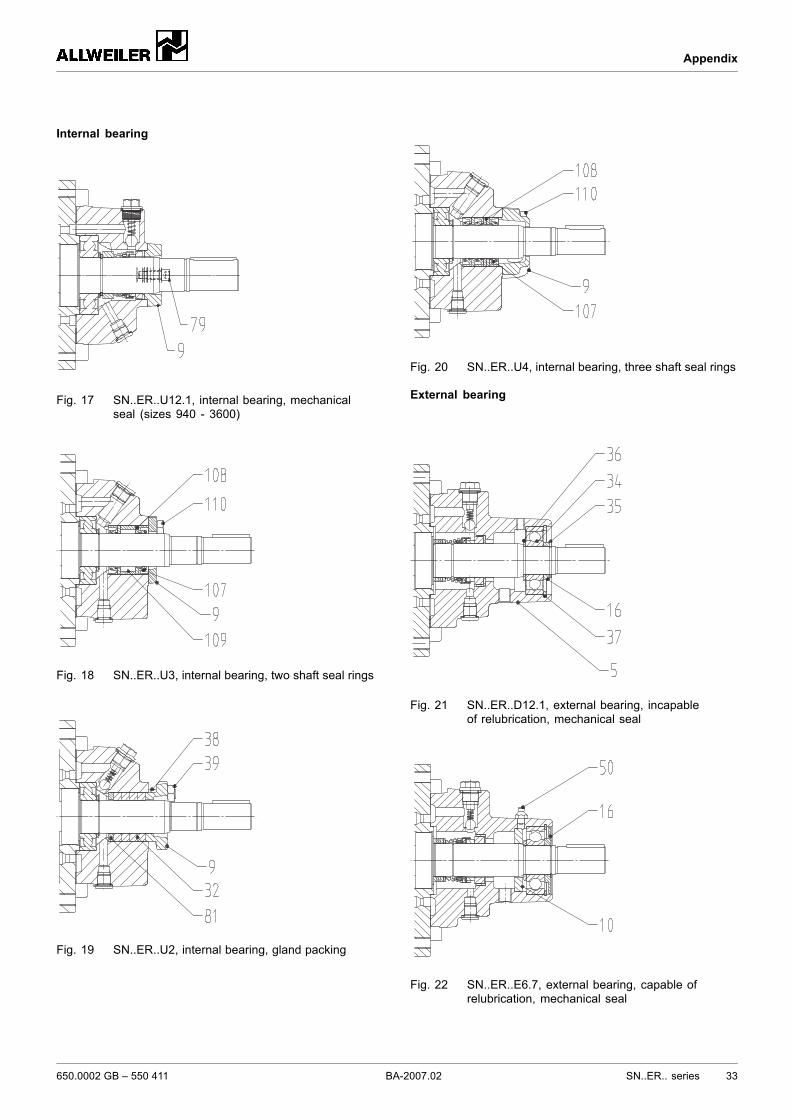
Internal bearing
Fig. 17 SN..ER..U12.1, internal bearing, mechanicalseal (sizes 940 - 3600)
Fig. 18 SN..ER..U3, internal bearing, two shaft seal rings
Fig. 19 SN..ER..U2, internal bearing, gland packing
Fig. 20 SN..ER..U4, internal bearing, three shaft seal rings
External bearing
Fig. 21 SN..ER..D12.1, external bearing, incapableof relubrication, mechanical seal
Fig. 22 SN..ER..E6.7, external bearing, capable ofrelubrication, mechanical seal
650.0002 GB – 550 411 BA-2007.02 SN..ER.. series 33
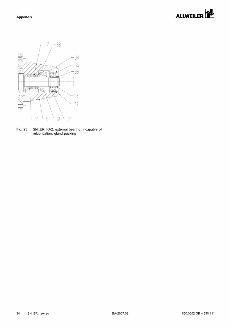
Appendix
Fig. 23 SN..ER..KA2, external bearing, incapable ofrelubrication, gland packing
34 SN..ER.. series BA-2007.02 650.0002 GB – 550 411
Appendix
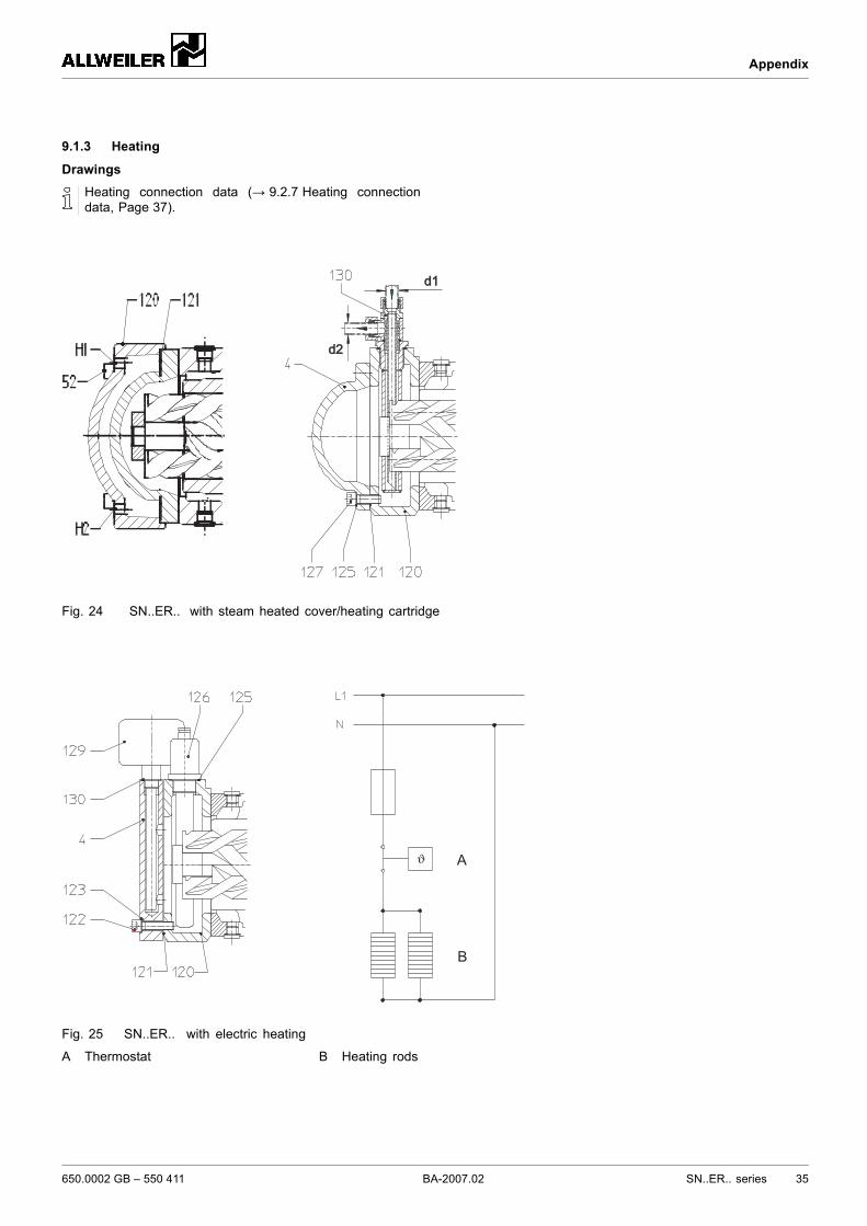
9.1.3 Heating
DrawingsHeating connection data (→ 9.2.7 Heating connectiondata, Page 37).
d1d1
d2d2
Fig. 24 SN..ER.. with steam heated cover/heating cartridge
ϑ A
B
Fig. 25 SN..ER.. with electric heating
A Thermostat B Heating rods
650.0002 GB – 550 411 BA-2007.02 SN..ER.. series 35
Appendix
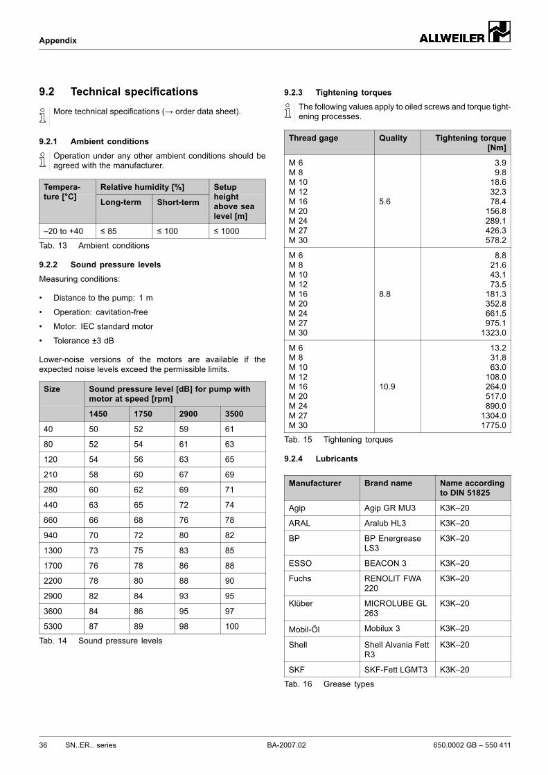
9.2 Technical specificationsMore technical specifications (→ order data sheet).
9.2.1 Ambient conditions
Operation under any other ambient conditions should beagreed with the manufacturer.
Relative humidity [%]Tempera-ture [°C] Long-term Short-term
Setupheightabove sealevel [m]
–20 to +40 ≤ 85 ≤ 100 ≤ 1000
Tab. 13 Ambient conditions
9.2.2 Sound pressure levels
Measuring conditions:
• Distance to the pump: 1 m
• Operation: cavitation-free
• Motor: IEC standard motor
• Tolerance ±3 dB
Lower-noise versions of the motors are available if theexpected noise levels exceed the permissible limits.
Sound pressure level [dB] for pump withmotor at speed [rpm]
Size
1450 1750 2900 3500
40 50 52 59 61
80 52 54 61 63
120 54 56 63 65
210 58 60 67 69
280 60 62 69 71
440 63 65 72 74
660 66 68 76 78
940 70 72 80 82
1300 73 75 83 85
1700 76 78 86 88
2200 78 80 88 90
2900 82 84 93 95
3600 84 86 95 97
5300 87 89 98 100
Tab. 14 Sound pressure levels
9.2.3 Tightening torquesThe following values apply to oiled screws and torque tight-ening processes.
Thread gage Quality Tightening torque[Nm]
M 6M 8M 10M 12M 16M 20M 24M 27M 30
5.6
3.99.818.632.378.4156.8289.1426.3578.2
M 6M 8M 10M 12M 16M 20M 24M 27M 30
8.8
8.821.643.173.5181.3352.8661.5975.11323.0
M 6M 8M 10M 12M 16M 20M 24M 27M 30
10.9
13.231.863.0108.0264.0517.0890.01304.01775.0
Tab. 15 Tightening torques
9.2.4 Lubricants
Manufacturer Brand name Name accordingto DIN 51825
Agip Agip GR MU3 K3K–20
ARAL Aralub HL3 K3K–20
BP BP EnergreaseLS3
K3K–20
ESSO BEACON 3 K3K–20
Fuchs RENOLIT FWA220
K3K–20
Klüber MICROLUBE GL263
K3K–20
Mobil-Öl Mobilux 3 K3K–20
Shell Shell Alvania FettR3
K3K–20
SKF SKF-Fett LGMT3 K3K–20
Tab. 16 Grease types
36 SN..ER.. series BA-2007.02 650.0002 GB – 550 411
Appendix
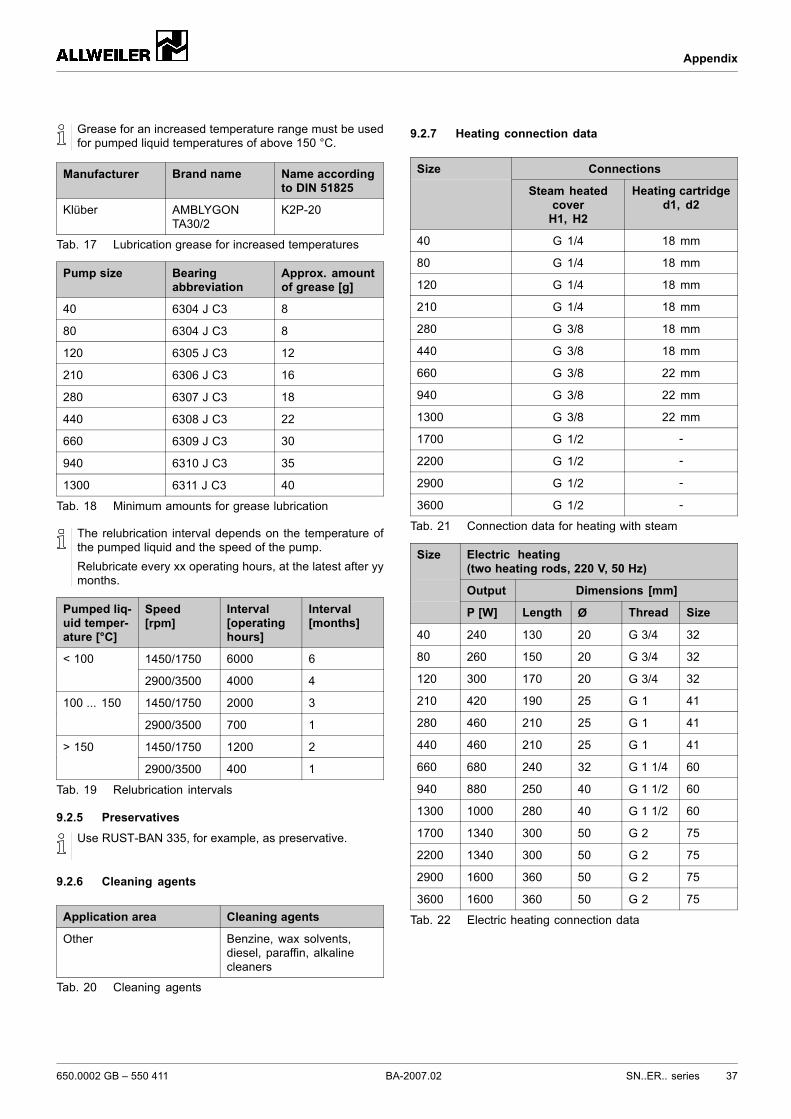
Grease for an increased temperature range must be usedfor pumped liquid temperatures of above 150 °C.
Manufacturer Brand name Name accordingto DIN 51825
Klüber AMBLYGONTA30/2
K2P-20
Tab. 17 Lubrication grease for increased temperatures
Pump size Bearingabbreviation
Approx. amountof grease [g]
40 6304 J C3 8
80 6304 J C3 8
120 6305 J C3 12
210 6306 J C3 16
280 6307 J C3 18
440 6308 J C3 22
660 6309 J C3 30
940 6310 J C3 35
1300 6311 J C3 40
Tab. 18 Minimum amounts for grease lubrication
The relubrication interval depends on the temperature ofthe pumped liquid and the speed of the pump.Relubricate every xx operating hours, at the latest after yymonths.
Pumped liq-uid temper-ature [°C]
Speed[rpm]
Interval[operatinghours]
Interval[months]
1450/1750 6000 6< 100
2900/3500 4000 4
1450/1750 2000 3100 ... 150
2900/3500 700 1
1450/1750 1200 2> 150
2900/3500 400 1
Tab. 19 Relubrication intervals
9.2.5 Preservatives
Use RUST-BAN 335, for example, as preservative.
9.2.6 Cleaning agents
Application area Cleaning agents
Other Benzine, wax solvents,diesel, paraffin, alkalinecleaners
Tab. 20 Cleaning agents
9.2.7 Heating connection data
ConnectionsSize
Steam heatedcoverH1, H2
Heating cartridged1, d2
40 G 1/4 18 mm
80 G 1/4 18 mm
120 G 1/4 18 mm
210 G 1/4 18 mm
280 G 3/8 18 mm
440 G 3/8 18 mm
660 G 3/8 22 mm
940 G 3/8 22 mm
1300 G 3/8 22 mm
1700 G 1/2 -
2200 G 1/2 -
2900 G 1/2 -
3600 G 1/2 -
Tab. 21 Connection data for heating with steam
Electric heating(two heating rods, 220 V, 50 Hz)
Output Dimensions [mm]
Size
P [W] Length Ø Thread Size
40 240 130 20 G 3/4 32
80 260 150 20 G 3/4 32
120 300 170 20 G 3/4 32
210 420 190 25 G 1 41
280 460 210 25 G 1 41
440 460 210 25 G 1 41
660 680 240 32 G 1 1/4 60
940 880 250 40 G 1 1/2 60
1300 1000 280 40 G 1 1/2 60
1700 1340 300 50 G 2 75
2200 1340 300 50 G 2 75
2900 1600 360 50 G 2 75
3600 1600 360 50 G 2 75
Tab. 22 Electric heating connection data
650.0002 GB – 550 411 BA-2007.02 SN..ER.. series 37
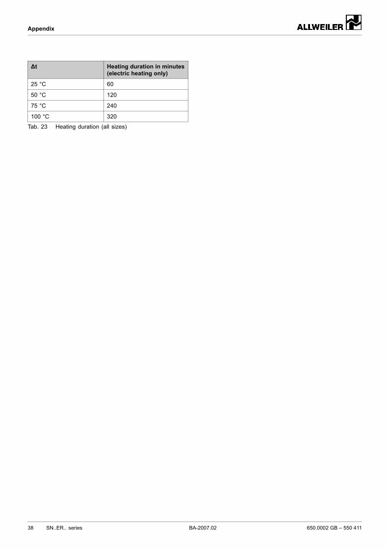
Appendix
∆t Heating duration in minutes(electric heating only)
25 °C 60
50 °C 120
75 °C 240
100 °C 320
Tab. 23 Heating duration (all sizes)
38 SN..ER.. series BA-2007.02 650.0002 GB – 550 411
Appendix
9.3 Safety certificate
650.0002 GB – 550 411 BA-2007.02 SN..ER.. series 39

Appendix
40 SN..ER.. series BA-2007.02 650.0002 GB – 550 411