Embed Size (px)
Citation preview
TR15-02
(2015.03.00150)NK$5,00
Marine type C
ontainer Refrigeration U
nitS
ervice Manual
LX
E10E
100 or later TR 15-02
Marine typeContainer Refrigeration Unit
Service Manual
Head Office. Umeda Center Bldg., 4-12, Nakazaki-Nishi 2-chome, Kita-ku, Osaka, 530-8323 Japan.
Tel: 06-6373-4338
Fax: 06-6373-7297
Tokyo Office. JR Shinagawa East Bldg., 11F 18-1, Konan 2-chome, Minato-ku Tokyo, 108-0075 Japan.
Tel: 03-6716-0420
Fax: 03-6716-0230
LXE10E100 or later(DECOSⅢh)
+H1-4_web・オンデマンド用.qxd 2015.03.11 15:27 ページ 1
1
Please read contents of this manual prior to operating unit.
This manual covers the minimum necessary information to maintainequipment at peak operating standards for LXE10E100 or later equippedwith controller DECOSⅢh. This includes safety information, unitspecifications, general unit information, maintenance procedures andrelated information (such as wiring and schematic diagrams), and how toenable and disable power supply.
In addition, refer to the manuals listed below.●Parts List●Operation Manual of Personal Computer Software
00_01-09_LXE10E100以降_E.qxd 15.3.3 3:47 PM ページ 1
CONTENTS2.6 Chartless function .......................................2-37
2.6.1 Chart indication function.......................2-372.6.2 P code (Pull down time indication) .......2-392.6.3 Chartless code display function............2-40
2.6.3.1 List of chartless code.....................2-402.6.3.2 H-code...........................................2-412.6.3.3 d-code ...........................................2-43
2.7 Communication modem ..............................2-443. SERVICE AND MAINTENANCE........................3-1
3.1 Maintenance service .....................................3-13.1.1 Recover refrigerant.................................3-13.1.2 Gauge manifold ......................................3-13.1.3 Automatic pump down............................3-33.1.4 Refrigerant recovery and charge............3-5
3.2 Main components and maintenance .............3-83.2.1 Scroll compressor...................................3-83.2.2 Procedure to remove evaporator fan motor ...3-113.2.3 Electronic expansion valve...................3-123.2.4 Suction modulation valve .....................3-133.2.5 Drier......................................................3-143.2.6 Solenoid valve ......................................3-153.2.7 Discharge pressure regulating valve ....3-163.2.8 Check valve..........................................3-163.2.9 High-pressure switch (HPS) .................3-173.2.10 High pressure transducer (HPT) ........3-173.2.11 Low pressure transducer (LPT)..........3-173.2.12 Fusible plug ........................................3-183.2.13 Sight glass..........................................3-193.2.14 Evacuation and dehydrating...............3-20
3.3 Periodic inspection items ............................3-223.4 Wiring diagram for external junction port ....3-24
3.4.1 Power plug (P1)....................................3-243.4.2 PC port (PPR1,2) .................................3-243.4.3 Remote monitoring connector
(RM) (Optional).....................................3-243.4.4 USDA sensor 1-3 junction port
(USDA1-3) (Optional)Cargo temperature sensor junction port (CTR) (Optional)...................................3-24
4. OPTIONAL DEVICES.........................................4-14.1 Cold treatment transport ...............................4-1
4.1.1 Setting the number of USDA sensorconnections ............................................4-1
4.1.2 USDA sensor calibration ........................4-14.1.3 USDA report ...........................................4-14.1.4 Battery check and replacement..............4-14.1.5 USDA sensor types and setting .............4-2
4.2 Ventilator outlet opening detection (FA sensor) ...4-34.3 Daikin temperature management system (optional)......4-64.4 Automatic setpoint change: ASC (optional)......4-84.5 Automatic cold treatment: ACT (optional) ......4-10
SAFETY PRECAUTIONS• Danger .................................................................4• Warning................................................................5
1. INTRODUCTION.................................................1-11.1 Operation range ............................................1-11.2 Specification..................................................1-11.3 Names of components ..................................1-2
1.3.1 Front view...............................................1-21.3.2 Rear and side section.............................1-51.3.3 Control box .............................................1-6
1.4 Protection devices specifications ..................1-91.5 Running operating pressures and current...1-101.6 Operating modes and control......................1-14
1.6.1 Frozen operation ..................................1-141.6.2 Chilled operation ..................................1-161.6.3 Defrost operation..................................1-181.6.4 Dehumidification control operation (optional) .....1-211.6.5 CA unit (optional)..................................1-221.6.6 Common control ...................................1-23
2. ELECTRONIC CONTROLLER...........................2-12.1 Electronic controller basic operation .............2-1
2.1.1 Control panel ..........................................2-12.2 Operation procedure .....................................2-4
2.2.1 Operation procedure flow chart ..............2-42.2.2 Mode operation procedure .....................2-7
1. CURRENT (Operation state) INDICATION MODE ...2-72. OPERATION SETTING MODE..............2-83. BATTERY MODE...................................2-94. MODE OPERATION ............................2-105. LED display LIGHT-OFF MODE ..........2-116. SENSOR INDICATION MODE.............2-127. TEMPERATURE RECORD SCROLL MODE ...2-158. ALARM RECORD SCROLL MODE .....2-179. PTI RECORD SCROLL MODE ............2-1810. OPTIONAL FUNCTION SETTING MODE ...2-1911. BASIC FUNCTION SETTING MODE...2-2012. OPTIONAL CONDITION SETTING MODE ...2-2213. INPUT DATA MODE ..........................2-2414. CONTROLLER SOFTWARE DOWNLOAD MODE...2-25
2.3 Information interchange with personal computer...2-262.3.1 Data logging .........................................2-26
2.4 Installation of software ....................................2-272.4.1 Installation of latest version software (version upgrade) ...2-27
2.5 Pre-trip inspection .......................................2-282.5.1 Manual inspection ................................2-302.5.2 Automatic PTI.......................................2-32
2.5.2.1 Automatic PTI selection mode.......2-322.5.2.2 Short PTI (S.PTI) ...........................2-332.5.2.3 Alarm list during PTI
(Pre-trip inspection) .......................2-342.5.2.4 Manual check (M.CHECK) ............2-35
00_01-09_LXE10E100以降_E.qxd 15.3.3 3:47 PM ページ 2
CONTENTS6. APPENDIX..........................................................6-1
6.1 Standard tightening torques for bolts ............6-16.2 Standard tightening torque for flare nut.........6-16.3 Resistance of motor coil and solenoid valve coil ...6-16.4 Temperature conversion table and temperature
sensor (SS/RS/DSS/DRS (option) /EIS/EOS/SGS/AMBS) characteristics table ....................6-2
6.5 Temperature conversion table and temperaturesensor (DCHS) characteristics table..................6-3
6.6 High and low pressure sensor characteristics table..6-46.7 HFC134a, temperature-vapor pressure
characteristics table ......................................6-56.8 USDA sensor characteristics table................6-66.9 Electric wiring pilot lamps and monitoring
circuit (option)................................................6-86.10 Fuse protection table...................................6-96.11 Schematic wiring diagram .........................6-116.12 Stereoscopic wiring diagram .....................6-12
5. TROUBLESHOOTING........................................5-15.1 Alarm diagnosis.............................................5-15.2 Refrigeration system and electrical system...5-245.3 Troubleshooting for automatic PTI (J-code)...5-365.4 Emergency operation ..................................5-38
5.4.1 Controller emergency operation ...........5-385.4.2 Controller short circuit operation ..........5-395.4.3 Electronic expansion valve emergency
operation ..............................................5-405.4.4 Suction modulation valve emergency
operation ..............................................5-415.5 Alarm display and backup function .............5-43
5.5.1 Alarm grouping .....................................5-435.5.2 Backup operation at the time of
control sensor (SS, RS) abnormality ....5-435.5.3 Backup operation at the time of
sensor abnormality ..............................5-435.6 Backup Battery............................................5-45
5.6.1 Function................................................5-455.6.2 Checking the remaining battery voltage...5-455.6.3 Handling used batteries........................5-46
00_01-09_LXE10E100以降_E.qxd 15.3.3 3:47 PM ページ 3
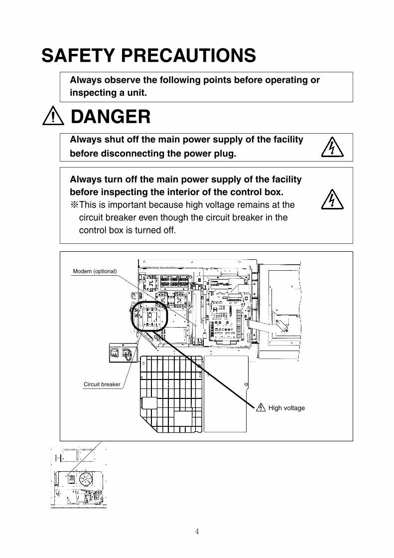
Always shut off the main power supply of the facility
before disconnecting the power plug.
4
SAFETY PRECAUTIONS
DANGER
Always turn off the main power supply of the facilitybefore inspecting the interior of the control box.※This is important because high voltage remains at the
circuit breaker even though the circuit breaker in thecontrol box is turned off.
Always observe the following points before operating orinspecting a unit.
High voltage
Circuit breaker
Modem (optional)
00_01-09_LXE10E100以降_E.qxd 15.3.3 3:47 PM ページ 4
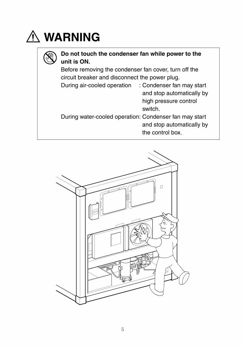
Do not touch the condenser fan while power to theunit is ON.Before removing the condenser fan cover, turn off thecircuit breaker and disconnect the power plug.During air-cooled operation : Condenser fan may start
and stop automatically byhigh pressure controlswitch.
During water-cooled operation: Condenser fan may startand stop automatically bythe control box.
5
WARNING
00_01-09_LXE10E100以降_E.qxd 15.3.3 3:47 PM ページ 5
6
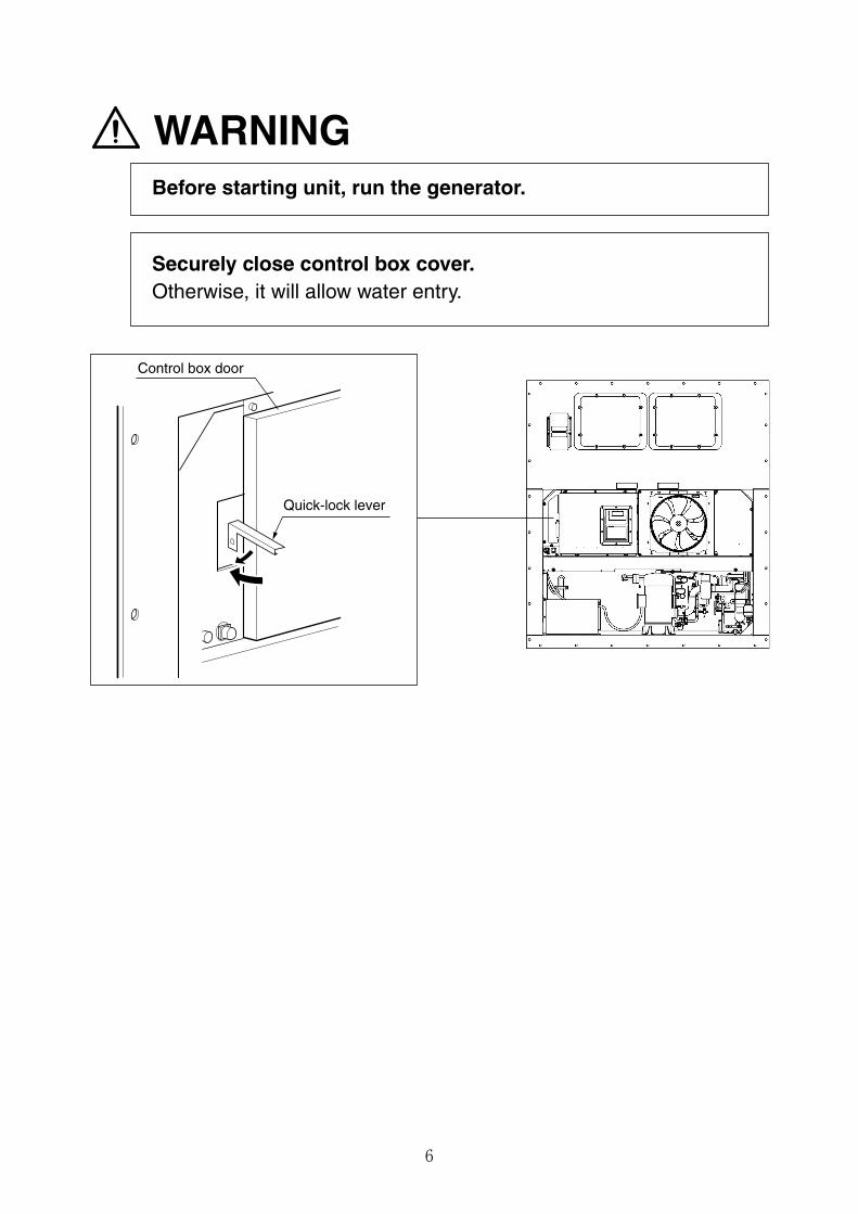
WARNINGBefore starting unit, run the generator.
Securely close control box cover.Otherwise, it will allow water entry.
Control box door
Quick-lock lever
00_01-09_LXE10E100以降_E.qxd 15.3.3 3:47 PM ページ 6
7
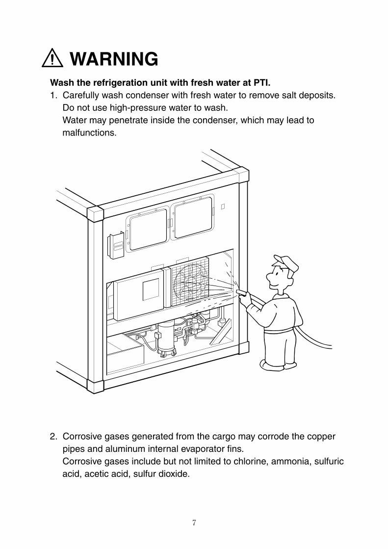
WARNINGWash the refrigeration unit with fresh water at PTI.1. Carefully wash condenser with fresh water to remove salt deposits.
Do not use high-pressure water to wash.Water may penetrate inside the condenser, which may lead tomalfunctions.
2. Corrosive gases generated from the cargo may corrode the copperpipes and aluminum internal evaporator fins.Corrosive gases include but not limited to chlorine, ammonia, sulfuricacid, acetic acid, sulfur dioxide.
00_01-09_LXE10E100以降_E.qxd 15.3.3 3:47 PM ページ 7
8
Use only those service tools certified for dedicated to HFC134a. (gauge manifold, etc)Do not use any tools for CFC12 or HCFC22.Service ports with exclusive quick joints for HFC134a are provided in the refrigerationunit to avoid improper refrigerant or refrigerant oil from entering refrigeration system.(Refer to clause 3.1.2)The charging hose and gauge port are not interchangeable with those of previousmodels using other refrigerants.
8
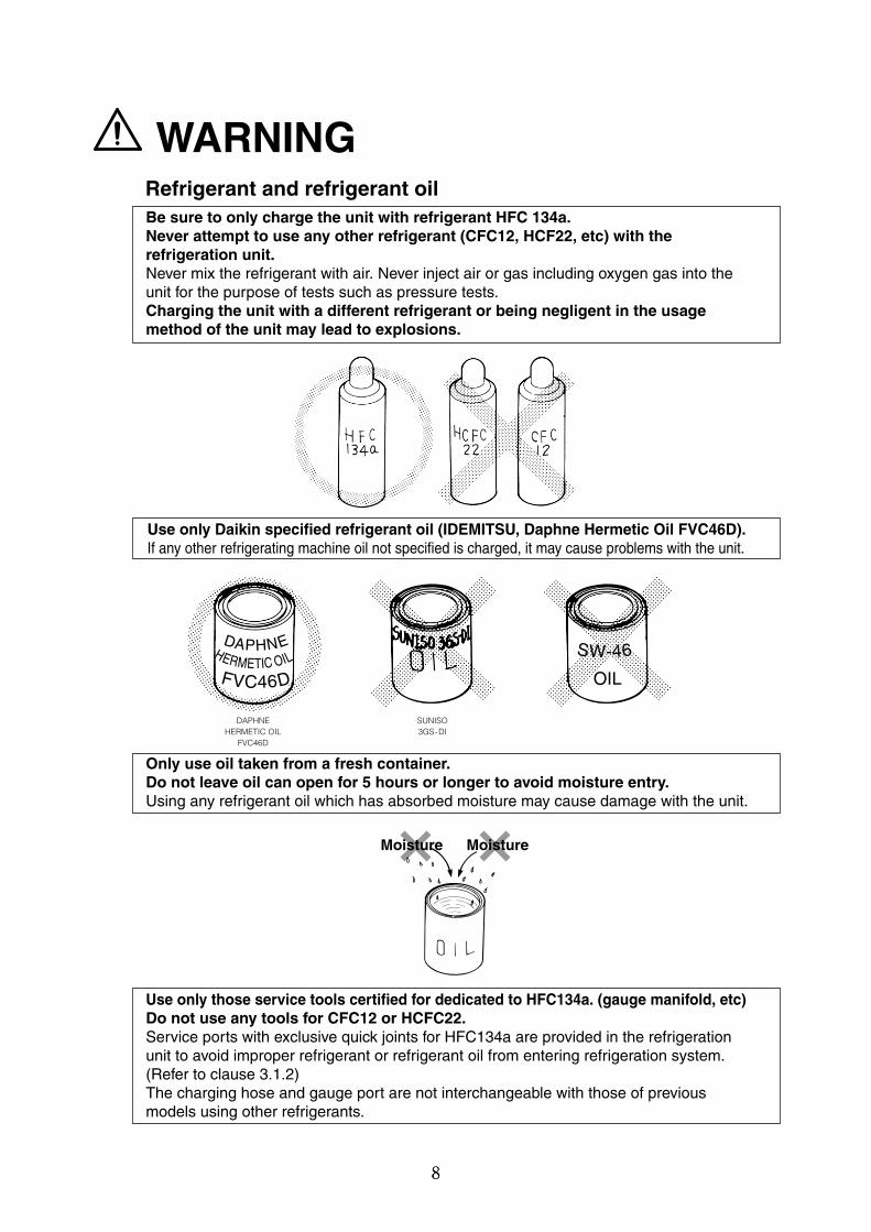
WARNINGRefrigerant and refrigerant oilBe sure to only charge the unit with refrigerant HFC 134a.Never attempt to use any other refrigerant (CFC12, HCF22, etc) with therefrigeration unit.Never mix the refrigerant with air. Never inject air or gas including oxygen gas into theunit for the purpose of tests such as pressure tests.Charging the unit with a different refrigerant or being negligent in the usagemethod of the unit may lead to explosions.
Use only Daikin specified refrigerant oil (IDEMITSU, Daphne Hermetic Oil FVC46D).If any other refrigerating machine oil not specified is charged, it may cause problems with the unit.
Only use oil taken from a fresh container.Do not leave oil can open for 5 hours or longer to avoid moisture entry.Using any refrigerant oil which has absorbed moisture may cause damage with the unit.
Moisture Moisture
DAPHNEHERMETIC OIL
FVC46D
SUNISO3GS-DI
DAPHNEHERMETIC OILFVC46D
SW-46
OIL
00_01-09_LXE10E100以降_E.qxd 15.3.3 3:47 PM ページ 8
9
CLASS 1 PRODUCT SPECIFIED BY THE LAW CONCERNING THE RECOVERY ANDDESTRUCTION OF FLUOROCARBONS OF FLUOROCARBONS
HFC IS USED FOR THIS PRODUCT AS A REFRIGERANT.
(1) EMISSION OF FLUOROCARBONS INTO THE ATOMOSPHERE WITHOUTPERMISSION IS PROHIBITED.
(2) RECOVERY OF FLUOROCARBONS IS MANDATORY WHEN SCRAPPING ANDSERVICING THIS PRODUCT.
(3) THE KIND OF FLUOROCARBON AND ITS AMOUNT ARE STATED IN THEMANUFACTURER'S LABEL OR THE ADDITIONALLY CHARGED AMOUNT LABEL.
This product contains greenhouse gases covered by Kyoto Protocol.Do not discharge refrigerant into atmosphere.
Refrigerant type : R134aGWP (1) value : 1430
(1) GWP=global warming potential
The refrigerant quantity is indicated on the unit name plate.
Important information regarding the refrigerant
When replacing the power cable, work must be carried out by the manufacturer, the distributor, or personnel qualified to conduct electrical work.
00_01-09_LXE10E100以降_E.qxd 15.3.3 3:47 PM ページ 9
1-1
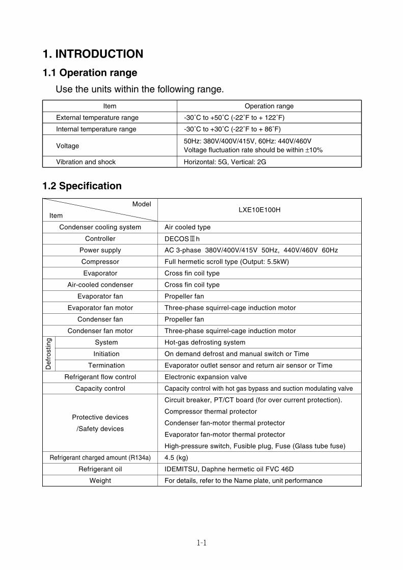
1.2 Specification
Model
Item
Condenser cooling system Air cooled type
Controller DECOS3h
Power supply AC 3-phase 380V/400V/415V 50Hz, 440V/460V 60Hz
Compressor Full hermetic scroll type (Output: 5.5kW)
Evaporator Cross fin coil type
Air-cooled condenser Cross fin coil type
Evaporator fan Propeller fan
Evaporator fan motor Three-phase squirrel-cage induction motor
Condenser fan Propeller fan
Condenser fan motor Three-phase squirrel-cage induction motor
Def
rost
ing Hot-gas defrosting system
On demand defrost and manual switch or Time
Evaporator outlet sensor and return air sensor or Time
Electronic expansion valve
Capacity control Capacity control with hot gas bypass and suction modulating valve
Protective devices
/Safety devices
Circuit breaker, PT/CT board (for over current protection).
Condenser fan-motor thermal protector
Evaporator fan-motor thermal protector
High-pressure switch, Fusible plug, Fuse (Glass tube fuse)
Refrigerant charged amount (R134a) 4.5 (kg)
Refrigerant oil IDEMITSU, Daphne hermetic oil FVC 46D
Weight
System
Initiation
Termination
Refrigerant flow control
Compressor thermal protector
1. INTRODUCTION
1.1 Operation range
Use the units within the following range.
External temperature range
Internal temperature range
Voltage
Vibration and shock
Operation range
-30˚C to +50˚C (-22˚F to + 122˚F)
-30˚C to +30˚C (-22˚F to + 86˚F)
50Hz: 380V/400V/415V, 60Hz: 440V/460V Voltage fluctuation rate should be within ±10%
Horizontal: 5G, Vertical: 2G
Item
LXE10E100H
For details, refer to the Name plate, unit performance
01_01-15_LXE10E100以降_E.qxd 2015.03.06 14:49 ページ 1-1
1-2
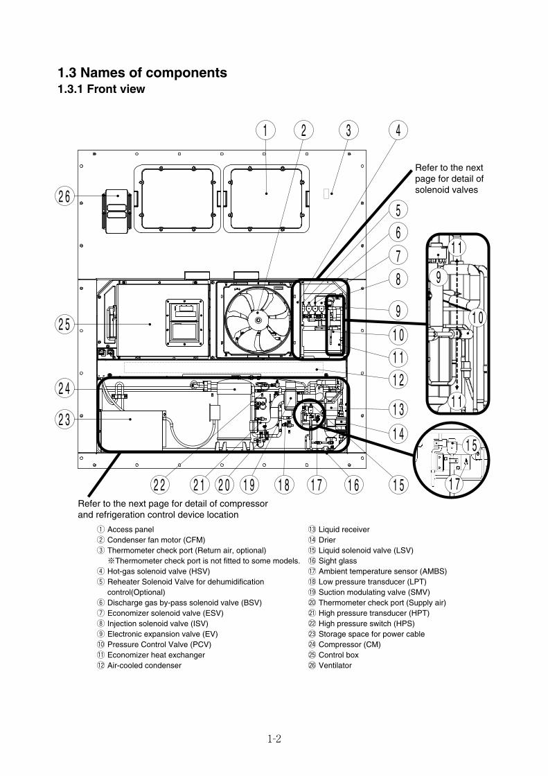
1.3 Names of components1.3.1 Front view
q Access panelw Condenser fan motor (CFM)e Thermometer check port (Return air, optional)※Thermometer check port is not fitted to some models.
r Hot-gas solenoid valve (HSV)t Reheater Solenoid Valve for dehumidification
control(Optional)y Discharge gas by-pass solenoid valve (BSV)u Economizer solenoid valve (ESV)i Injection solenoid valve (ISV)o Electronic expansion valve (EV)!0 Pressure Control Valve (PCV)!1 Economizer heat exchanger!2 Air-cooled condenser
!3 Liquid receiver!4 Drier!5 Liquid solenoid valve (LSV)!6 Sight glass!7 Ambient temperature sensor (AMBS)!8 Low pressure transducer (LPT)!9 Suction modulating valve (SMV)@0 Thermometer check port (Supply air)@1 High pressure transducer (HPT)@2 High pressure switch (HPS)@3 Storage space for power cable@4 Compressor (CM)@5 Control box@6 Ventilator
Refer to the next page for detail of solenoid valves
Refer to the next page for detail of compressor and refrigeration control device location
1 1
1 1
1 7
1 5
9
1 0
1 32 4
5678
91 01 11 2
1 3
1 4
1 51 61 71 81 92 02 12 2
2 3
2 4
2 5
2 6
01_01-15_LXE10E100以降_E.qxd 2015.03.06 14:49 ページ 1-2

1-3
●LXE10E100G
· Solenoid valve location
[Valve]BSV :Discharge gas bypass Solenoid ValveEV :Electronic Expansion ValveESV :Economizer Solenoid ValveHSV :Hot gas Solenoid ValveISV :Injection Solenoid ValvePCV :Pressure Control ValveRSV :Reheater Solenoid Valve (Optional)
for dehumidification control
[Sensor]AMBS: Ambient temperature sensorDCHS: Discharge Gas Temperature SensorHPS : High Pressure SwitchHPT : High Pressure transducerLPT : Low pressure transducerSGS : Compressor suction pipe temperature sensor
[Valve]SMV : Suction modulating valveDPR : Discharge Pressure Regulator ValveLSV : Liquid solenoid valve
· Compressor and refrigeration control device location
Liquid receiver
DrierLSV
Sight glass
SMV
AMBS
DCHS
HPT
HPS
1 Lowpressure(Serviceport)
2 Highpressure(Serviceport)
4 Highpressure(Serviceport)
LPT 5 Liquidpressure(Serviceport)
3 Liquidpressure(Serviceport)Service port
SGS DPR
[Service port]q Low pressurew High pressuree Liquid pressurer High pressuret Liquid pressure
For operation pressure check
Refrigerant recovery or vacuumdryFor Refrigerant charging(For details, refer to page 3-5.)
HSV RSV BSV
ESV ISV EV PCV
01_01-15_LXE10E100以降_E.qxd 2015.03.06 14:49 ページ 1-3
1-4
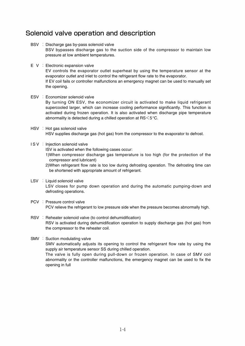
Solenoid valve operation and description
BSV :Discharge gas by-pass solenoid valveBSV bypasses discharge gas to the suction side of the compressor to maintain lowpressure at low ambient temperatures.
E V :Electronic expansion valveEV controls the evaporator outlet superheat by using the temperature sensor at theevaporator outlet and inlet to control the refrigerant flow rate to the evaporator.If EV coil fails or controller malfunctions an emergency magnet can be used to manually setthe opening.
ESV :Economizer solenoid valveBy turning ON ESV, the economizer circuit is activated to make liquid refrigerantsupercooled larger, which can increase cooling performance significantly. This function isactivated during frozen operation. It is also activated when discharge pipe temperatureabnormality is detected during a chilled operation at RS<5°C.
HSV :Hot gas solenoid valveHSV supplies discharge gas (hot gas) from the compressor to the evaporator to defrost.
I S V : Injection solenoid valveISV is activated when the following cases occur:1)When compressor discharge gas temperature is too high (for the protection of the
compressor and lubricant) 2)When refrigerant flow rate is too low during defrosting operation. The defrosting time can
be shortened with appropriate amount of refrigerant.
LSV :Liquid solenoid valveLSV closes for pump down operation and during the automatic pumping-down anddefrosting operations.
PCV :Pressure control valvePCV relieve the refrigerant to low pressure side when the pressure becomes abnormally high.
RSV :Reheater solenoid valve (to control dehumidification)RSV is activated during dehumidification operation to supply discharge gas (hot gas) fromthe compressor to the reheater coil.
SMV :Suction modulating valveSMV automatically adjusts its opening to control the refrigerant flow rate by using thesupply air temperature sensor SS during chilled operation.The valve is fully open during pull-down or frozen operation. In case of SMV coilabnormality or the controller malfunctions, the emergency magnet can be used to fix theopening in full
01_01-15_LXE10E100以降_E.qxd 2015.03.06 14:49 ページ 1-4
1-5
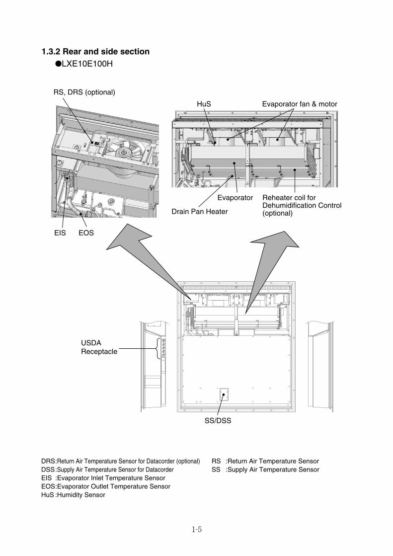
1.3.2 Rear and side section●LXE10E100H
USDAReceptacle
RS, DRS (optional)
EIS EOS
Evaporator
HuS Evaporator fan & motor
Drain Pan Heater
Reheater coil forDehumidification Control(optional)
SS/DSS
DRS:Return Air Temperature Sensor for Datacorder (optional)DSS:Supply Air Temperature Sensor for DatacorderEIS :Evaporator Inlet Temperature SensorEOS:Evaporator Outlet Temperature SensorHuS :Humidity Sensor
RS :Return Air Temperature SensorSS :Supply Air Temperature Sensor
01_01-15_LXE10E100以降_E.qxd 2015.03.06 14:49 ページ 1-5
1-6
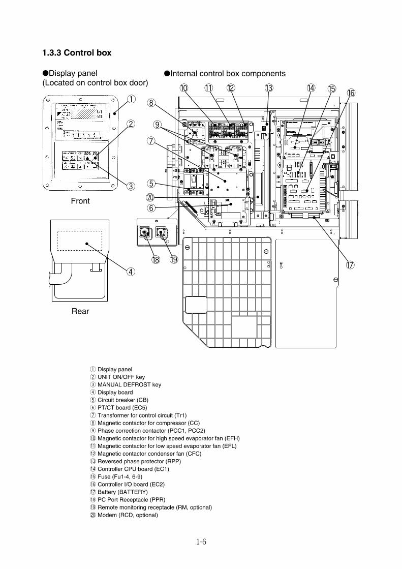
q Display panelw UNIT ON/OFF keye MANUAL DEFROST keyr Display boardt Circuit breaker (CB)y PT/CT board (EC5)u Transformer for control circuit (Tr1)i Magnetic contactor for compressor (CC)o Phase correction contactor (PCC1, PCC2)!0 Magnetic contactor for high speed evaporator fan (EFH)!1 Magnetic contactor for low speed evaporator fan (EFL)!2 Magnetic contactor condenser fan (CFC)!3 Reversed phase protector (RPP)!4 Controller CPU board (EC1)!5 Fuse (Fu1-4, 6-9)!6 Controller I/O board (EC2)!7 Battery (BATTERY)!8 PC Port Receptacle (PPR)!9 Remote monitoring receptacle (RM, optional)@0 Modem (RCD, optional)
1.3.3 Control box
①
②
③
④
●Internal control box components●Display panel(Located on control box door)
Front
Rear
⑨
⑩ ⑪ ⑫ ⑬ ⑭ ⑮
⑰
⑯
⑲⑱
⑤
⑥
⑦
⑳
⑧
01_01-15_LXE10E100以降_E.qxd 2015.03.06 14:49 ページ 1-6
1-7
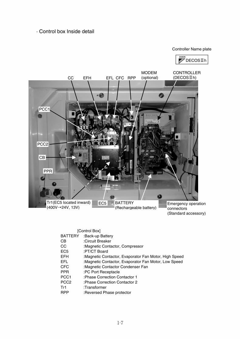
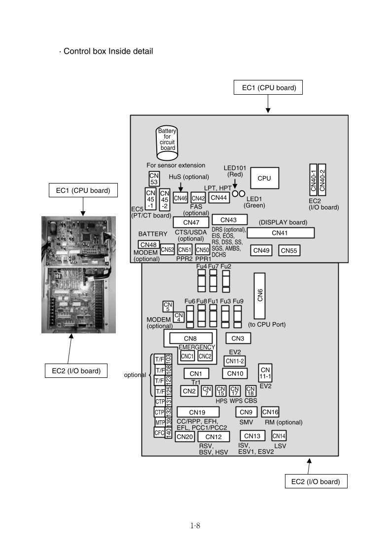
· Control box Inside detail
[Control Box]BATTERY :Back-up BatteryCB :Circuit BreakerCC :Magnetic Contactor, CompressorEC5 :PT/CT BoardEFH :Magnetic Contactor, Evaporator Fan Motor, High SpeedEFL :Magnetic Contactor, Evaporator Fan Motor, Low SpeedCFC :Magnetic Contactor Condenser FanPPR :PC Port ReceptaclePCC1 :Phase Correction Contactor 1PCC2 :Phase Correction Contactor 2Tr1 :TransformerRPP :Reversed Phase protector
Controller Name plate
DECOSⅢhDAIKIN
CC EFH EFL CFC RPPMODEM(optional)
PCC2
CB
PCC1
Tr1(EC5 located inward)(400V→24V, 13V)
Emergency operation connectors (Standard accessory)
BATTERY(Rechargeable battery)
PPR
EC5
CONTROLLER(DECOS3h)
01_01-15_LXE10E100以降_E.qxd 2015.03.06 14:49 ページ 1-7
1-8
· Control box Inside detail
EC2 (I/O board)
EC2 (I/O board)
EC5(PT/CT board)
EC2(I/O board)
(to CPU Port)
MODEM (optional)
MODEM (optional)
CN52 CN51PPR2
Fu4
Fu6 Fu8Fu1 Fu3 Fu9
Fu7 Fu2PPR1CN50
HPS
CN1Tr1
103
T/F
T/F
T/F
T/F
108
123
125
CTP
CTP
MTP
CFC
131
132
139
140
CN5
CN4
CN7
CN15
CN17
CN18
BATTERY
CN9
SMV
CN16
RM (optional)
WPS CBS
CN3
CN49
CN8
CNC1 CNC2EMERGENCY
CN
6CN55
CN47
CTS/USDA(optional)
CN
40-1
CN
40-2
DRS (optional), EIS, EOS,RS, DSS, SS, SGS, AMBS, DCHS
CN43
CN44
LPT, HPT
LED101(Red)
LED1(Green)
CPU
FAS(optional)
CN42CN46
HuS (optional)
For sensor extension
Battery for
circuit board
optional
CN14
LSV
CN13
ISV, ESV1, ESV2
CN12RSV, BSV, HSV
CN2
CN19CC/RPP, EFH,EFL, PCC1/PCC2
CN41
(DISPLAY board)
EV2
CN10
EC1 (CPU board)
EC1 (CPU board)
CN53
CN45-1
CN45-2
CN48
CN11-1
CN11-2
CN20
EV2
01_01-15_LXE10E100以降_E.qxd 2015.03.06 14:49 ページ 1-8
–
1-9
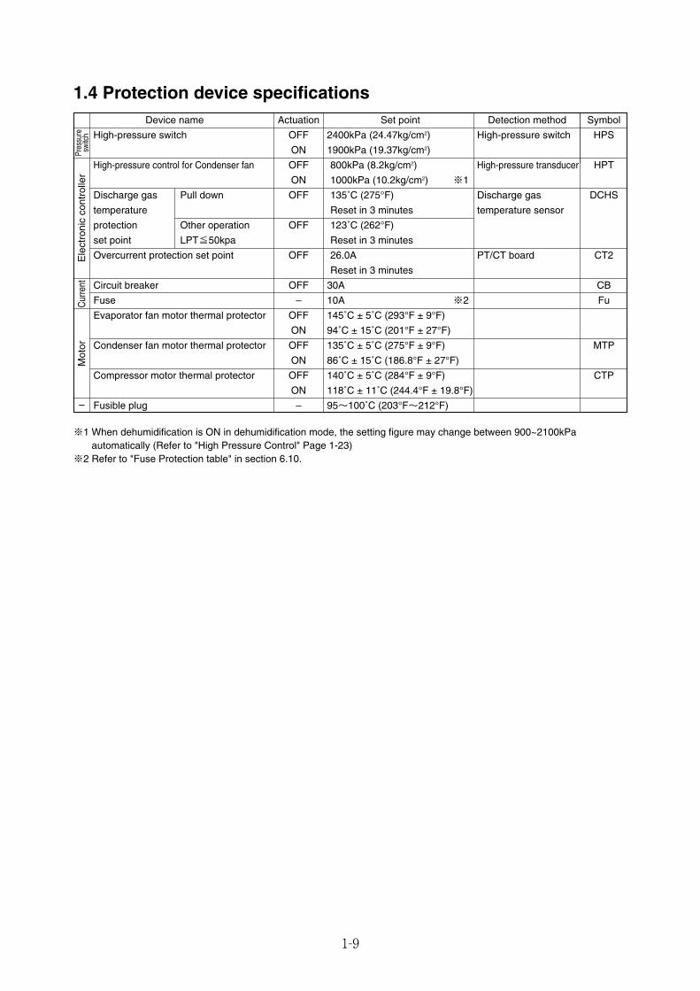
1.4 Protection device specifications
※1 When dehumidification is ON in dehumidification mode, the setting figure may change between 900~2100kPaautomatically (Refer to "High Pressure Control" Page 1-23)
※2 Refer to "Fuse Protection table" in section 6.10.
Cur
rent
Device name Actuation Set point Detection method Symbol
High-pressure switch OFF 2400kPa (24.47kg/cm2) High-pressure switch HPS
ON 1900kPa (19.37kg/cm2)
High-pressure control for Condenser fan OFF 800kPa (8.2kg/cm2) High-pressure transducer HPT
ON 1000kPa (10.2kg/cm2) ※1
Discharge gas Pull down OFF 135˚C (275°F) Discharge gas DCHS
temperature Reset in 3 minutes temperature sensor
protection Other operation OFF 123˚C (262°F)
set point LPT≦50kpa Reset in 3 minutes
Overcurrent protection set point OFF 26.0A PT/CT board CT2
Reset in 3 minutes
Circuit breaker OFF 30A CB
Fuse – 10A ※2 Fu
Evaporator fan motor thermal protector OFF 145˚C ± 5˚C (293°F ± 9°F)
ON 94˚C ± 15˚C (201°F ± 27°F)
Condenser fan motor thermal protector OFF 135˚C ± 5˚C (275°F ± 9°F) MTP
ON 86˚C ± 15˚C (186.8°F ± 27°F)
Compressor motor thermal protector OFF 140˚C ± 5˚C (284°F ± 9°F) CTP
ON 118˚C ± 11˚C (244.4°F ± 19.8°F)
Fusible plug – 95~100˚C (203°F~212°F)
Ele
ctro
nic
cont
rolle
rPr
essu
resw
itch
Mot
or
01_01-15_LXE10E100以降_E.qxd 2015.03.06 14:49 ページ 1-9
1-10
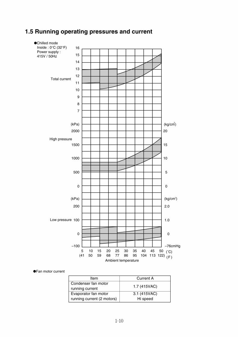
1.5 Running operating pressures and current
●Chilled mode Inside : 0°C (32°F) Power supply : 415V / 50Hz
7
8
9
10
11
12
13
14
15
16
(kPa)
(kPa)
(˚C)
( F )
(kg/cm2)
Ambient temperature
0
5 10 15 20 25 30 35 40 45 50(41 50 59 68 77 86 95 104 113 122)
0 0
500 5
1000 10
1500 15
2000 20
0
100 1.0
200 2.0
–76cmHg–100
Low pressure
High pressure
Total current
(kg/cm)2
Item Current ACondenser fan motor
1.7 (415VAC)running currentEvaporator fan motor 3.1 (415VAC)running current (2 motors) Hi speed
●Fan motor current
01_01-15_LXE10E100以降_E.qxd 2015.03.06 14:49 ページ 1-10
1-11
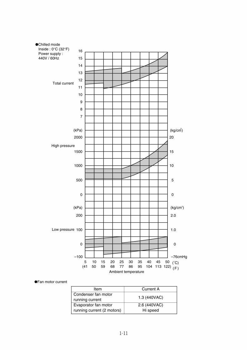
●Chilled mode Inside : 0°C (32°F) Power supply : 440V / 60Hz
7
8
9
10
11
12
13
14
15
16
(kPa)
(kPa)
(˚C)
( F )
(kg/cm2)
Ambient temperature
0
5 10 15 20 25 30 35 40 45 50(41 50 59 68 77 86 95 104 113 122)
0 0
500 5
1000 10
1500 15
2000 20
0
100 1.0
200 2.0
–76cmHg–100
Low pressure
High pressure
Total current
(kg/cm)2
Item Current ACondenser fan motor
1.3 (440VAC)running currentEvaporator fan motor 2.6 (440VAC)running current (2 motors) Hi speed
●Fan motor current
01_01-15_LXE10E100以降_E.qxd 2015.03.06 14:49 ページ 1-11
1-12
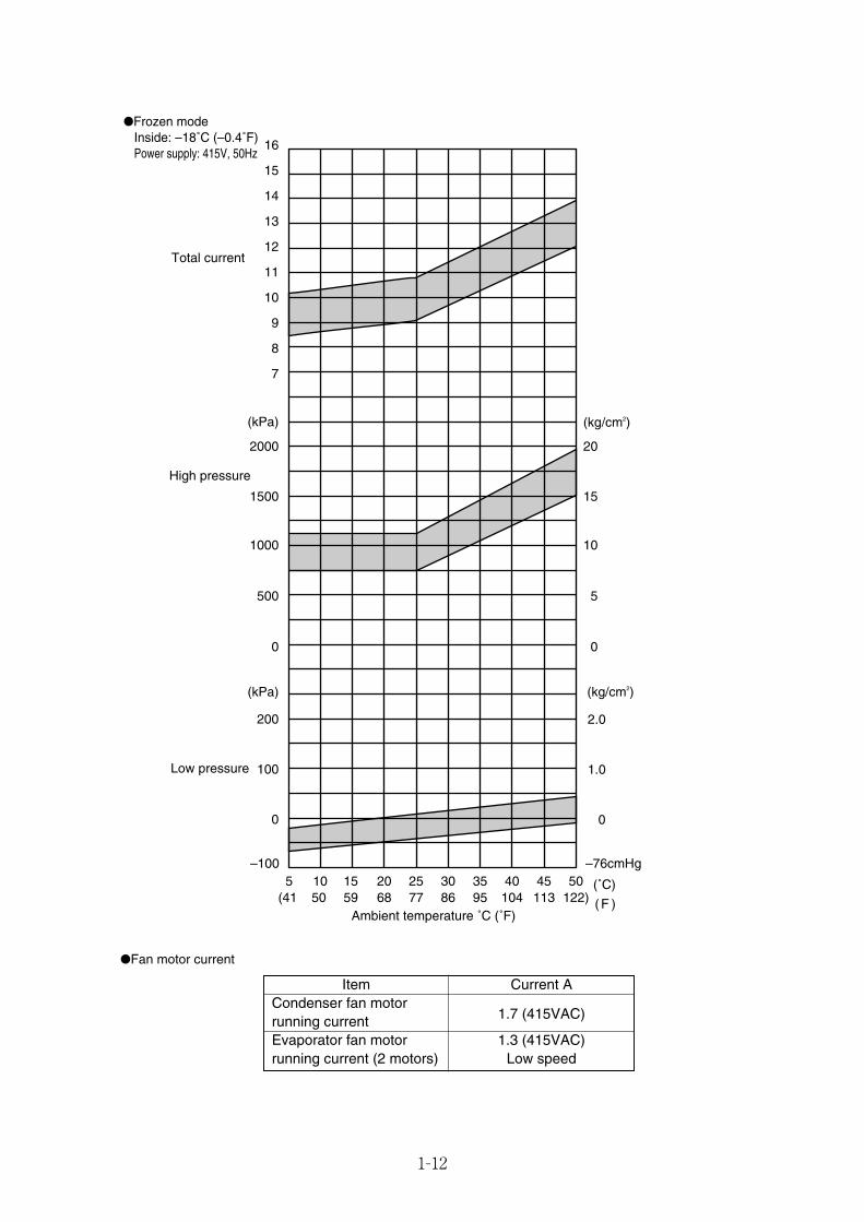
●Frozen mode Inside: –18˚C (–0.4˚F) Power supply: 415V, 50Hz
7
8
9
10
11
12
13
14
15
16
(kPa)
(kPa)
(˚C)
( F )
(kg/cm2)
Ambient temperature ˚C (˚F)
0
5 10 15 20 25 30 35 40 45 50(41 50 59 68 77 86 95 104 113 122)
0 0
500 5
1000 10
1500 15
2000 20
0
100 1.0
200 2.0
–76cmHg–100
Low pressure
High pressure
Total current
(kg/cm2)
Item Current ACondenser fan motor
1.7 (415VAC)running currentEvaporator fan motor 1.3 (415VAC)running current (2 motors) Low speed
●Fan motor current
01_01-15_LXE10E100以降_E.qxd 2015.03.06 14:49 ページ 1-12
1-13
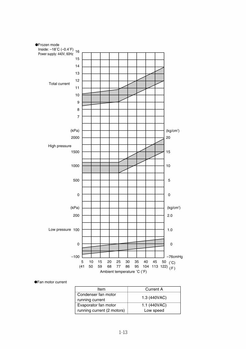
●Frozen mode Inside: –18˚C (–0.4˚F) Power supply: 440V, 60Hz
7
8
9
10
11
12
13
14
15
16
(kPa)
(kPa)
(˚C)
( F )
(kg/cm2)
Ambient temperature ˚C (˚F)
0
5 10 15 20 25 30 35 40 45 50(41 50 59 68 77 86 95 104 113 122)
0 0
500 5
1000 10
1500 15
2000 20
0
100 1.0
200 2.0
–76cmHg–100
Low pressure
High pressure
Total current
(kg/cm2)
Item Current ACondenser fan motor
1.3 (440VAC)running currentEvaporator fan motor 1.1 (440VAC)running current (2 motors) Low speed
●Fan motor current
01_01-15_LXE10E100以降_E.qxd 2015.03.06 14:49 ページ 1-13
1-14
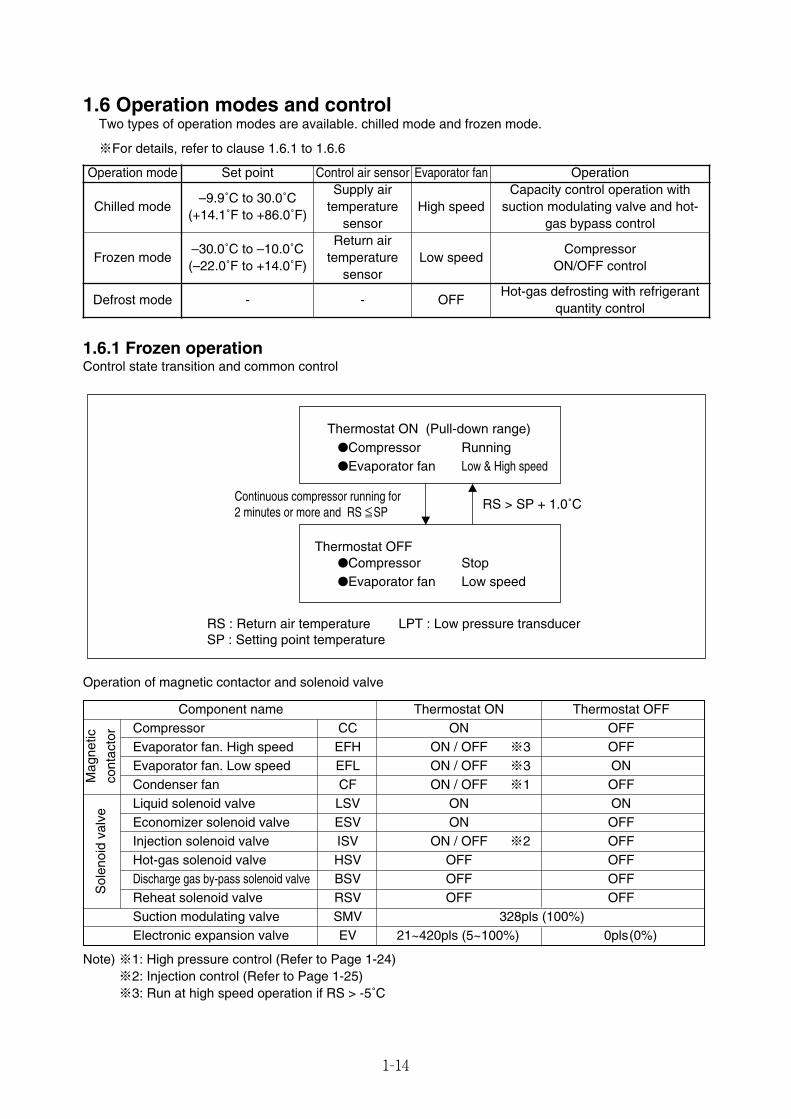
1.6 Operation modes and controlTwo types of operation modes are available. chilled mode and frozen mode.
※For details, refer to clause 1.6.1 to 1.6.6
Operation mode Set point Control air sensor Evaporator fan Operation
Chilled mode–9.9˚C to 30.0˚C
(+14.1˚F to +86.0˚F)
Supply airtemperature
sensorHigh speed
Capacity control operation withsuction modulating valve and hot-
gas bypass control
Frozen mode–30.0˚C to –10.0˚C(–22.0˚F to +14.0˚F)
Return airtemperature
sensorLow speed
Compressor ON/OFF control
- - OFFHot-gas defrosting with refrigerant
quantity controlDefrost mode
Sol
enoi
dva
lve
Mag
netic
cont
acto
r
1.6.1 Frozen operationControl state transition and common control
Component name Thermostat ON Thermostat OFFCompressor CC ON OFFEvaporator fan. High speed EFH ON / OFF ※3 OFFEvaporator fan. Low speed EFL ON / OFF ※3 ONCondenser fan CF ON / OFF ※1 OFFLiquid solenoid valve LSV ON ONEconomizer solenoid valve ESV ON OFFInjection solenoid valve ISV ON / OFF ※2 OFFHot-gas solenoid valve HSV OFF OFFDischarge gas by-pass solenoid valve BSV OFF OFFReheat solenoid valve RSV OFF OFFSuction modulating valve SMV 328pls (100%)Electronic expansion valve EV 21~420pls (5~100%) 0pls(0%)
Note) ※1: High pressure control (Refer to Page 1-24)※2: Injection control (Refer to Page 1-25)※3: Run at high speed operation if RS > -5˚C
RS > SP + 1.0˚C
RS : Return air temperature LPT : Low pressure transducerSP : Setting point temperature
Thermostat OFF●Compressor Stop●Evaporator fan Low speed
Thermostat ON (Pull-down range)●Compressor Running●Evaporator fan Low & High speed
≤≤Continuous compressor running for 2 minutes or more and RS SP
Operation of magnetic contactor and solenoid valve
01_01-15_LXE10E100以降_E.qxd 2015.03.06 14:49 ページ 1-14
1-15
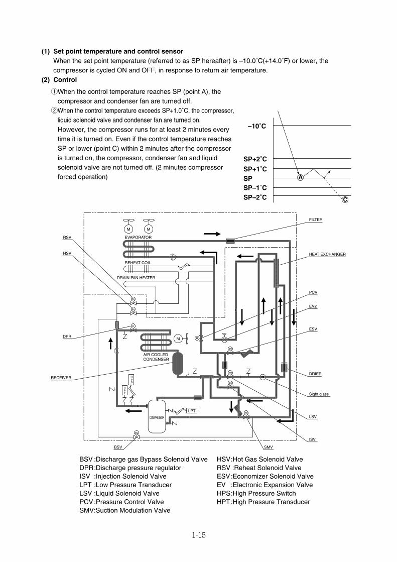
(1) Set point temperature and control sensorWhen the set point temperature (referred to as SP hereafter) is –10.0˚C(+14.0˚F) or lower, thecompressor is cycled ON and OFF, in response to return air temperature.
(2) Control
qWhen the control temperature reaches SP (point A), thecompressor and condenser fan are turned off.
wWhen the control temperature exceeds SP+1.0˚C, the compressor,liquid solenoid valve and condenser fan are turned on.However, the compressor runs for at least 2 minutes everytime it is turned on. Even if the control temperature reachesSP or lower (point C) within 2 minutes after the compressoris turned on, the compressor, condenser fan and liquidsolenoid valve are not turned off. (2 minutes compressorforced operation)
SP+2˚C
–10˚C
SP+1˚C
SP–1˚CSP–2˚C
SP A
C
R
R
SV
SV
SV
SV
SV
SV
SV
M M
M
EVAPORATOR
REHEAT COIL
DRAIN PAN HEATER
AIR COOLEDCONDENSER
HPS
HPT
LPT
COMPRESSOR
RSV
HSV
DPR
BSV SMV
RECEIVER
ISV
LSV
Sight glass
DRIER
ESV
EV2
PCV
HEAT EXCHANGER
FILTER
D
L
L
8
BSV :Discharge gas Bypass Solenoid Valve HSV:Hot Gas Solenoid ValveDPR:Discharge pressure regulator RSV :Reheat Solenoid ValveISV :Injection Solenoid Valve ESV:Economizer Solenoid ValveLPT :Low Pressure Transducer EV :Electronic Expansion ValveLSV :Liquid Solenoid Valve HPS:High Pressure SwitchPCV:Pressure Control Valve HPT:High Pressure TransducerSMV:Suction Modulation Valve
01_01-15_LXE10E100以降_E.qxd 2015.03.06 14:49 ページ 1-15
1-16
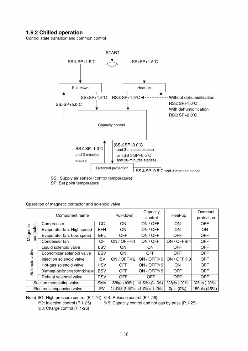
Component name Pull-downCapacity
Heat-upOvercool
control protectionCompressor CC ON ON / OFF ON OFFEvaporator fan. High speed EFH ON ON / OFF ON ONEvaporator fan. Low speed EFL OFF ON / OFF OFF OFFCondenser fan CF ON / OFF※1 ON / OFF ON / OFF※4 OFFLiquid solenoid valve LSV ON ON OFF OFFEconomizer solenoid valve ESV ON OFF OFF OFFInjection solenoid valve ISV ON / OFF※2 ON / OFF※5 ON / OFF※3 OFFHot-gas solenoid valve HSV OFF ON / OFF※5 ON OFFDischarge gas by-pass solenoid valve BSV OFF ON / OFF※5 OFF OFFReheat solenoid valve RSV OFF OFF OFF OFF
Suction modulating valve SMV 328pls (100%) 10~328pls (3~100%) 328pls (100%) 328pls (100%)Electronic expansion valve EV 21~420pls (5~100%) 48~420pls (11~100%) 0pls (0%) 189pls (45%)
1.6.2 Chilled operationControl state transition and common control
START
SS<SP+1.5˚CSS≧SP+1.5˚C
Overcool protection
Capacity control
Pull-down Heat-up
SS : Supply air sensor (control temperature)SP: Set point temperature
SS<SP+1.5˚C RS≧SP+1.0˚C Without dehumidification:RS≧SP+1.0˚CWith dehumidificationRS≧SP+2.0˚C
SS>SP+5.0˚C
SS≧SP+1.0˚Cand 3-minutes
elapse
(SS≦SP–3.0˚C and 3-minutes elapse)
or (SS≦SP–0.5˚C and 30-minutes elapse)
SS≦SP–0.5˚C and 3-minutes elapse
Mag
netic
cont
acto
r
Operation of magnetic contactor and solenoid valve
Note) ※1: High pressure control (P.1-24) ※4: Release control (P.1-26)※2: Injection control (P.1-25) ※5: Capacity control and hot gas by-pass (P.1-25)※3: Charge control (P.1-26)
Sol
enoi
dva
lve
01_16-26_LXE10E100以降_E.qxd 15.3.5 11:32 AM ページ 1-16
1-17
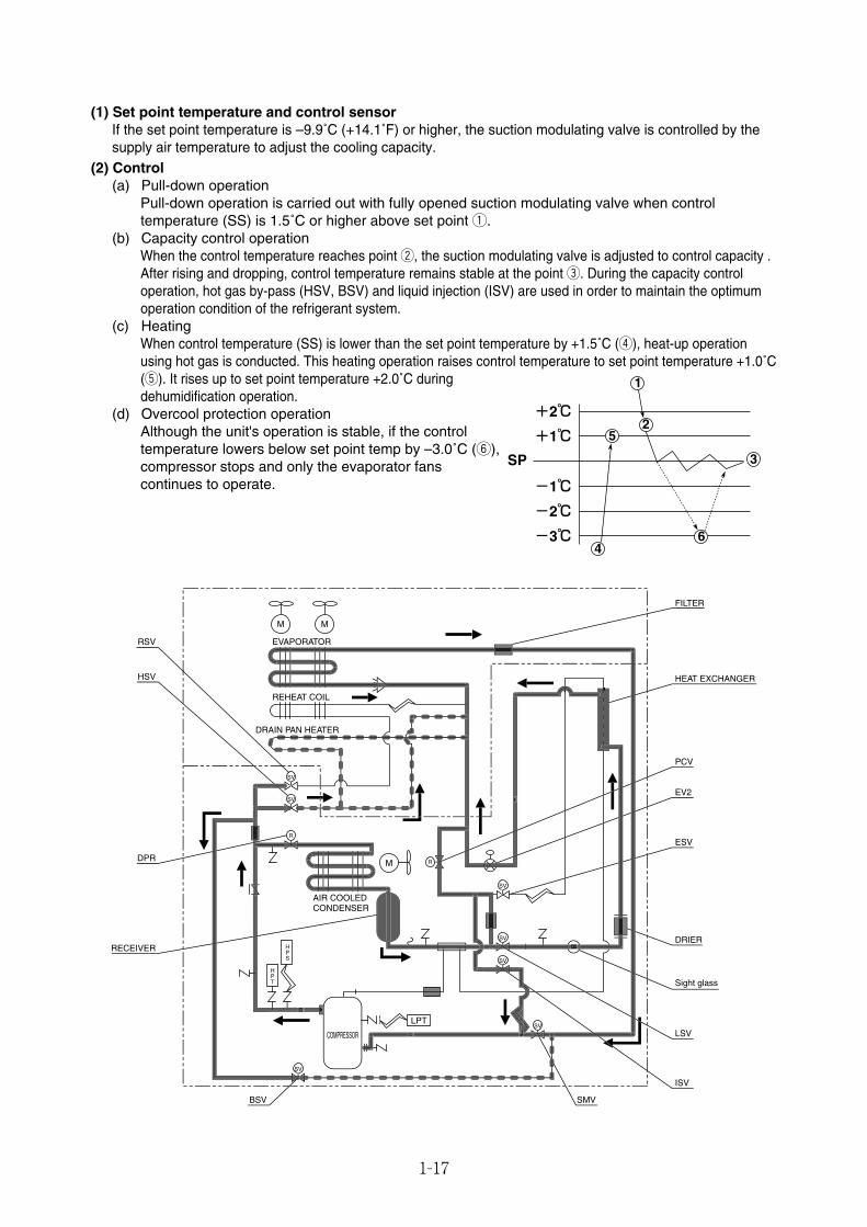
(1) Set point temperature and control sensorIf the set point temperature is –9.9˚C (+14.1˚F) or higher, the suction modulating valve is controlled by thesupply air temperature to adjust the cooling capacity.
(2) Control(a) Pull-down operation
Pull-down operation is carried out with fully opened suction modulating valve when controltemperature (SS) is 1.5˚C or higher above set point q.
(b) Capacity control operationWhen the control temperature reaches point w, the suction modulating valve is adjusted to control capacity .After rising and dropping, control temperature remains stable at the point e. During the capacity controloperation, hot gas by-pass (HSV, BSV) and liquid injection (ISV) are used in order to maintain the optimumoperation condition of the refrigerant system.
(c) HeatingWhen control temperature (SS) is lower than the set point temperature by +1.5˚C (r), heat-up operationusing hot gas is conducted. This heating operation raises control temperature to set point temperature +1.0˚C(t). It rises up to set point temperature +2.0˚C duringdehumidification operation.
(d) Overcool protection operationAlthough the unit's operation is stable, if the controltemperature lowers below set point temp by –3.0˚C (y),compressor stops and only the evaporator fanscontinues to operate.
R
R
SV
SV
SV
SV
SV
SV
SV
M M
M
EVAPORATOR
REHEAT COIL
DRAIN PAN HEATER
AIR COOLEDCONDENSER
HPS
HPT
LPT
COMPRESSOR
RSV
HSV
DPR
BSV SMV
RECEIVER
ISV
LSV
Sight glass
DRIER
ESV
EV2
PCV
HEAT EXCHANGER
FILTER
L
L
8
D
-3℃
-2℃
-1℃
+1℃
+2℃
SP
1
6
25
4
3
01_16-26_LXE10E100以降_E.qxd 15.3.5 11:32 AM ページ 1-17
1-18
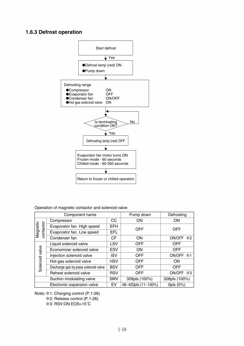
1.6.3 Defrost operation
Start defrost
Is terminatingcondition OK?
●Defrost lamp (red) ON
●Pump down
Defrosting range
Defrosting lamp (red) OFF
Return to frozen or chilled operation
Evaporator fan motor turns ONFrozen mode - 60 secondsChilled mode - 60-300 seconds
●Compressor ON●Evaporator fan OFF●Condenser fan ON/OFF●Hot gas solenoid valve ON
No
Yes
Yes
Component name Pump down DefrostingCompressor CC ON ONEvaporator fan. High speed EFH
OFF OFFEvaporator fan. Low speed EFLCondenser fan CF ON ON/OFF ※2Liquid solenoid valve LSV OFF OFFEconomizer solenoid valve ESV ON OFFInjection solenoid valve ISV OFF ON/OFF ※1Hot-gas solenoid valve HSV OFF ONDischarge gas by-pass solenoid valve BSV OFF OFFReheat solenoid valve RSV OFF ON/OFF ※3Suction modulating valve SMV 328pls (100%) 328pls (100%)Electronic expansion valve EV 48~420pls (11~100%) 0pls (0%)
Operation of magnetic contactor and solenoid valve
Note) ※1: Charging control (P.1-26)※2: Release control (P.1-26)※3: RSV:ON EOS>15˚C
Mag
netic
cont
acto
rS
olen
oid
valv
e
01_16-26_LXE10E100以降_E.qxd 15.3.5 11:32 AM ページ 1-18
1-19
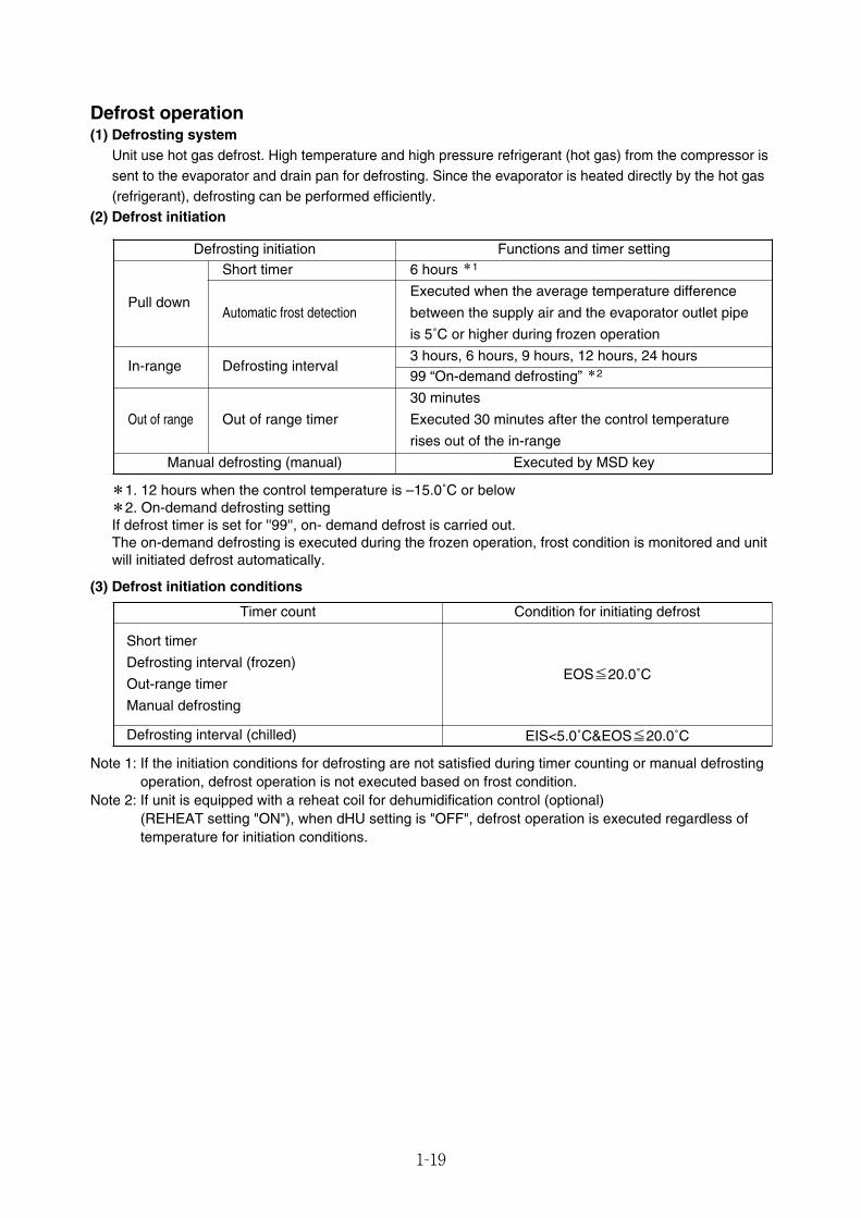
Defrost operation(1) Defrosting system
Unit use hot gas defrost. High temperature and high pressure refrigerant (hot gas) from the compressor issent to the evaporator and drain pan for defrosting. Since the evaporator is heated directly by the hot gas(refrigerant), defrosting can be performed efficiently.
(2) Defrost initiation
*1. 12 hours when the control temperature is –15.0˚C or below*2. On-demand defrosting settingIf defrost timer is set for ''99'', on- demand defrost is carried out.The on-demand defrosting is executed during the frozen operation, frost condition is monitored and unitwill initiated defrost automatically.
(3) Defrost initiation conditions
Timer count
Short timer
Defrosting interval (frozen)
Out-range timer
Manual defrosting
EOS≦20.0˚C
EIS<5.0˚C&EOS≦20.0˚C
Condition for initiating defrost
Defrosting interval (chilled)
Note 1: If the initiation conditions for defrosting are not satisfied during timer counting or manual defrostingoperation, defrost operation is not executed based on frost condition.
Note 2: If unit is equipped with a reheat coil for dehumidification control (optional)(REHEAT setting "ON"), when dHU setting is "OFF", defrost operation is executed regardless oftemperature for initiation conditions.
Defrosting initiation Functions and timer setting
Pull down
Short timer 6 hours *1
Automatic frost detection
Executed when the average temperature difference
between the supply air and the evaporator outlet pipe
is 5˚C or higher during frozen operation
In-range Defrosting interval3 hours, 6 hours, 9 hours, 12 hours, 24 hours99 “On-demand defrosting” *2
Out of range Out of range timer
30 minutes
Executed 30 minutes after the control temperature
rises out of the in-range
Manual defrosting (manual) Executed by MSD key
01_16-26_LXE10E100以降_E.qxd 15.3.5 11:32 AM ページ 1-19
1-20
R
R
SV
SV
SV
SV
SV
SV
SV
M M
M
EVAPORATOR
REHEAT COIL
DRAIN PAN HEATER
AIR COOLEDCONDENSER
HPS
HPT
LPT
COMPRESSOR
8
L
RSV
HSV
DPR
BSV SMV
RECEIVER
ISV
LSV
Sight glass
DRIER
ESV
EV2
PCV
HEAT EXCHANGER
FILTER
L
D
Release※1
Charge※1
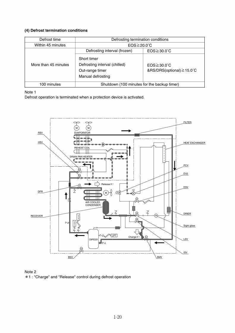
(4) Defrost termination conditions
Defrost time Defrosting termination conditionsWithin 45 minutes EOS≧20.0˚C
EOS≧30.0˚C
Short timer
Defrosting interval (chilled)
Out-range timer
Manual defrosting
EOS≧30.0˚C&RS/DRS(optional)≧15.0˚C
Shutdown (100 minutes for the backup timer)
Defrosting interval (frozen)
More than 45 minutes
100 minutes
Note 1Defrost operation is terminated when a protection device is activated.
Note 2*1 : "Charge" and "Release" control during defrost operation
01_16-26_LXE10E100以降_E.qxd 15.3.5 11:32 AM ページ 1-20
1-21
R
R
SV
SV
SV
SV
SV
SV
SV
M M
M
EVAPORATOR
REHEAT COIL
DRAIN PAN HEATER
AIR COOLEDCONDENSER
HPS
HPT
LPT
COMPRESSOR
RSV
HSV
DPR
BSV SMV
RECEIVER
ISV
LSV
Sight glass
DRIER
ESV
EV2
PCV
HEAT EXCHANGER
FILTER
L
D
Release※1
Charge※1
L
8
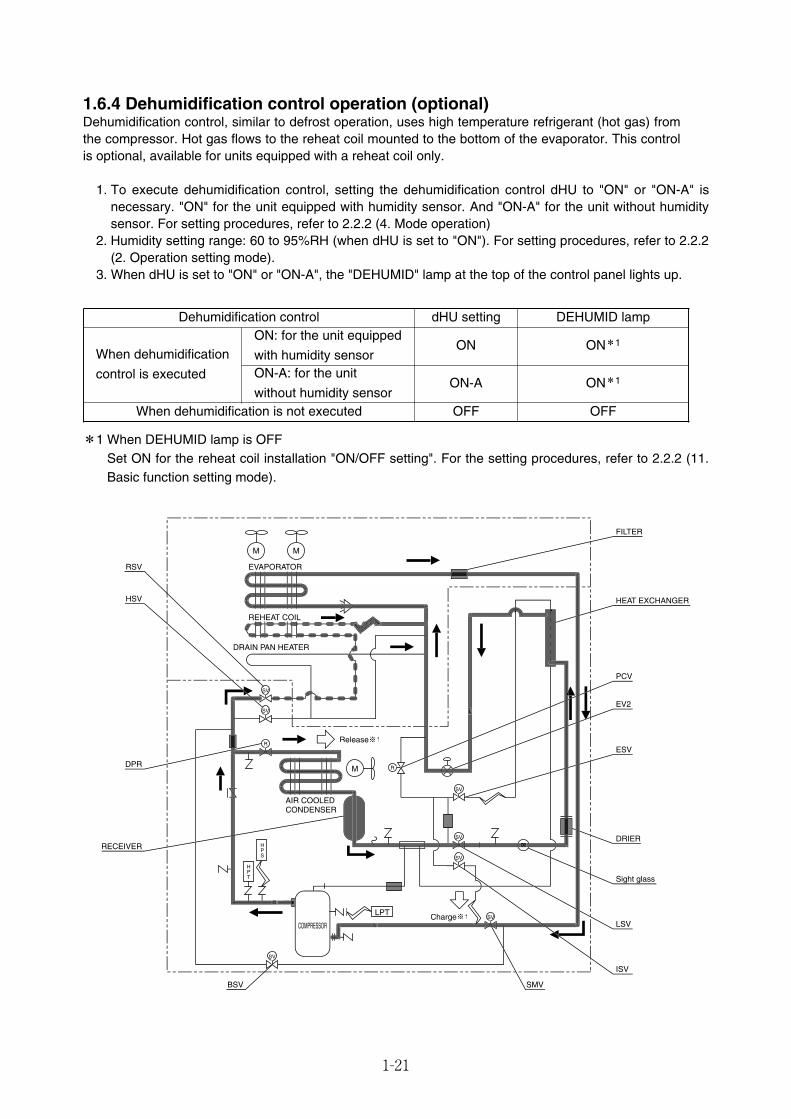
1.6.4 Dehumidification control operation (optional)Dehumidification control, similar to defrost operation, uses high temperature refrigerant (hot gas) fromthe compressor. Hot gas flows to the reheat coil mounted to the bottom of the evaporator. This controlis optional, available for units equipped with a reheat coil only.
1. To execute dehumidification control, setting the dehumidification control dHU to "ON" or "ON-A" isnecessary. "ON" for the unit equipped with humidity sensor. And "ON-A" for the unit without humiditysensor. For setting procedures, refer to 2.2.2 (4. Mode operation)
2. Humidity setting range: 60 to 95%RH (when dHU is set to "ON"). For setting procedures, refer to 2.2.2(2. Operation setting mode).
3. When dHU is set to "ON" or "ON-A", the "DEHUMID" lamp at the top of the control panel lights up.
Dehumidification control
ON*1
ON-A ON*1
ONWhen dehumidification
control is executed
When dehumidification is not executed
DEHUMID lampON: for the unit equipped
with humidity sensorON-A: for the unit
without humidity sensorOFF
*1 When DEHUMID lamp is OFFSet ON for the reheat coil installation "ON/OFF setting". For the setting procedures, refer to 2.2.2 (11.Basic function setting mode).
dHU setting
OFF
01_16-26_LXE10E100以降_E.qxd 15.3.5 11:32 AM ページ 1-21
1-22
1.6.5 CA unit (optional)• The CA (Control Atmosphere) unit controls the composition of the atmospheric gas within the container
box of the Marine type Container Refrigeration Unit. Controlling the concentration of oxygen and carbondioxide within the container box makes it possible to maintain the freshness of fruits and vegetablesduring transportation.
• The VPSA method (*) is used to adjust the concentration of oxygen, the air pump is used to draw inatmosphere, the built-in adsorption cylinders are used to separate the oxygen, the remaining lowconcentration oxygen gas is pressurized again with the air pump, and then low concentration oxygen gasis supplied to the inside of the container box. The carbon dioxide concentration is adjusted by therespiration of the fruits and vegetables and by supplied outside air into the container box by air pump.
(*) VPSA method for Vacuum Pressure Swing Adsorption. In this method, two adsorption cylinders areused to perform adsorption at atmospheric pressure and desorption in a vacuum.
Use the CA unit in the following set temperature range within the reefer box.
ItemRefrigeration unit internal temperature range –2˚C to +20˚C (+28.4˚F to 68˚F)
*For details on the CA unit, refer to the CA service manual for the Marine type Container RefrigerationUnit.
Operation range
01_16-26_LXE10E100以降_E.qxd 15.3.5 11:32 AM ページ 1-22
1-23
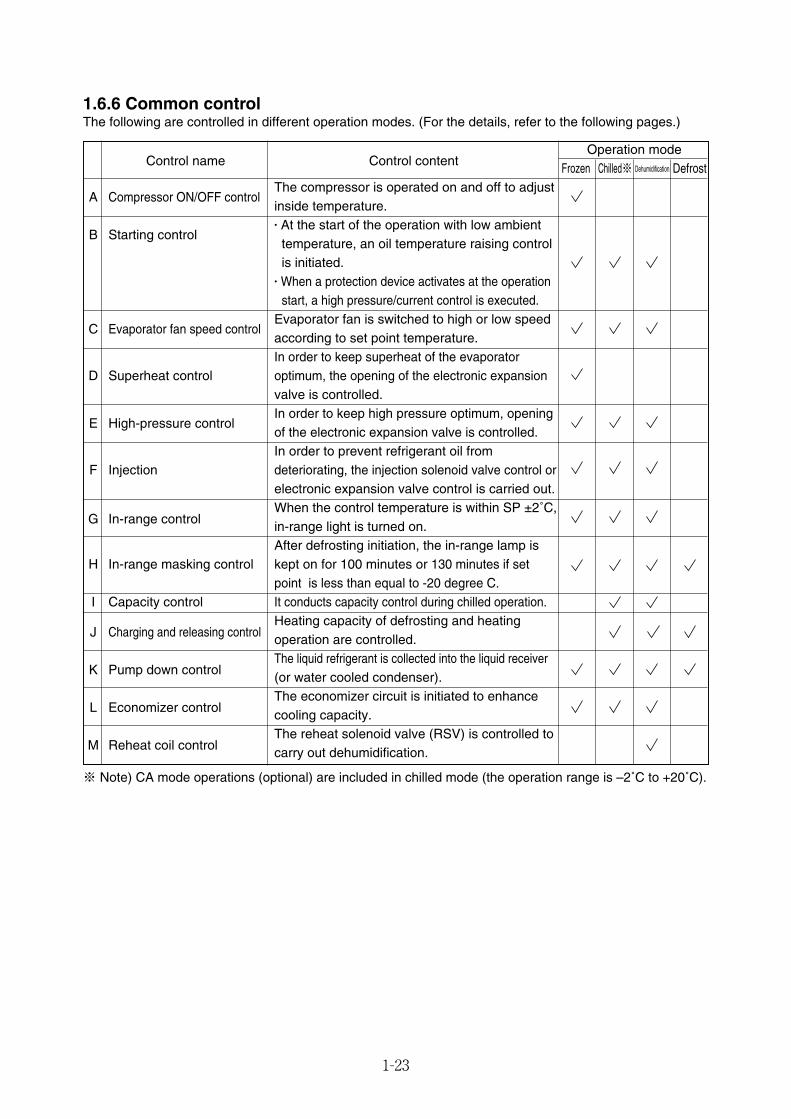
1.6.6 Common controlThe following are controlled in different operation modes. (For the details, refer to the following pages.)
DehumidificationControl name Control content
Operation modeFrozen Chilled※ Defrost
A Compressor ON/OFF controlThe compressor is operated on and off to adjust inside temperature.
B Starting control� At the start of the operation with low ambient temperature, an oil temperature raising control is initiated.
� When a protection device activates at the operationstart, a high pressure/current control is executed.
C Evaporator fan speed controlEvaporator fan is switched to high or low speed according to set point temperature.In order to keep superheat of the evaporator
D Superheat control optimum, the opening of the electronic expansionvalve is controlled.
E High-pressure controlIn order to keep high pressure optimum, opening of the electronic expansion valve is controlled.In order to prevent refrigerant oil from
F Injection deteriorating, the injection solenoid valve control orelectronic expansion valve control is carried out.
G In-range controlWhen the control temperature is within SP ±2˚C,in-range light is turned on.After defrosting initiation, the in-range lamp is
H In-range masking control kept on for 100 minutes or 130 minutes if set point is less than equal to -20 degree C.
I Capacity control It conducts capacity control during chilled operation.
J Charging and releasing controlHeating capacity of defrosting and heating operation are controlled.
K Pump down controlThe liquid refrigerant is collected into the liquid receiver(or water cooled condenser).
L Economizer controlThe economizer circuit is initiated to enhance cooling capacity.
M Reheat coil controlThe reheat solenoid valve (RSV) is controlled to carry out dehumidification.
※ Note) CA mode operations (optional) are included in chilled mode (the operation range is –2˚C to +20˚C).
01_16-26_LXE10E100以降_E.qxd 15.3.5 11:32 AM ページ 1-23
1-24
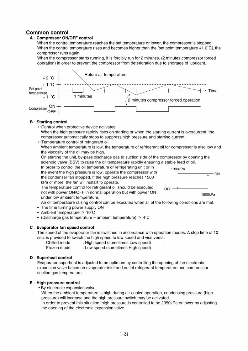
Common controlA : Compressor ON/OFF control
When the control temperature reaches the set temperature or lower, the compressor is stopped.When the control temperature rises and becomes higher than the [set point temperature +1.0˚C], thecompressor runs again.When the compressor starts running, it is forcibly run for 2 minutes. (2 minutes compressor forcedoperation) in order to prevent the compressor from deterioration due to shortage of lubricant.
B : Starting control™Control when protective device activated
When the high pressure rapidly rises on starting or when the starting current is overcurrent, thecompressor automatically stops to suppress high pressure and starting current.
™Temperature control of refrigerant oilWhen ambient temperature is low, the temperature of refrigerant oil for compressor is also low andthe viscosity of the oil may be high.On starting the unit, by-pass discharge gas to suction side of the compressor by opening thesolenoid valve (BSV) to raise the oil temperature rapidly ensuring a stable feed of oil.In order to control the oil temperature of refrigerating unit or inthe event the high pressure is low, operate the compressor withthe condenser fan stopped. If the high pressure reaches 1500kPa or more, the fan will restart to operate.The temperature control for refrigerant oil should be executednot with power ON/OFF in normal operation but with power ONunder low ambient temperature.An oil temperature raising control can be executed when all of the following conditions are met.
• The time turning power supply ON• Ambient temperature ≦ 10˚C• (Discharge gas temperature – ambient temperature) ≦ 4˚C
C : Evaporator fan speed controlThe speed of the evaporator fan is switched in accordance with operation modes. A stop time of 10sec. is provided to switch the high speed to low speed and vice versa.
Chilled mode : High speed (sometimes Low speed)Frozen mode : Low speed (sometimes High speed)
D : Superheat controlEvaporator superheat is adjusted to be optimum by controlling the opening of the electronicexpansion valve based on evaporator inlet and outlet refrigerant temperature and compressorsuction gas temperature.
E : High-pressure control• By electronic expansion valve
When the ambient temperature is high during air-cooled operation, condensing pressure (highpressure) will increase and the high pressure switch may be activated.In order to prevent this situation, high pressure is controlled to be 2350kPa or lower by adjustingthe opening of the electronic expansion valve.
+ 2 ˚C
+ 1 ˚C
– 1 ˚C
ONOFF
Set point temperature
Compressor
1 minutes2 minutes compressor forced operation
Time
Return air temperature
ON
OFF
1500kPa
1300kPa
01_16-26_LXE10E100以降_E.qxd 15.3.5 11:32 AM ページ 1-24
1-25
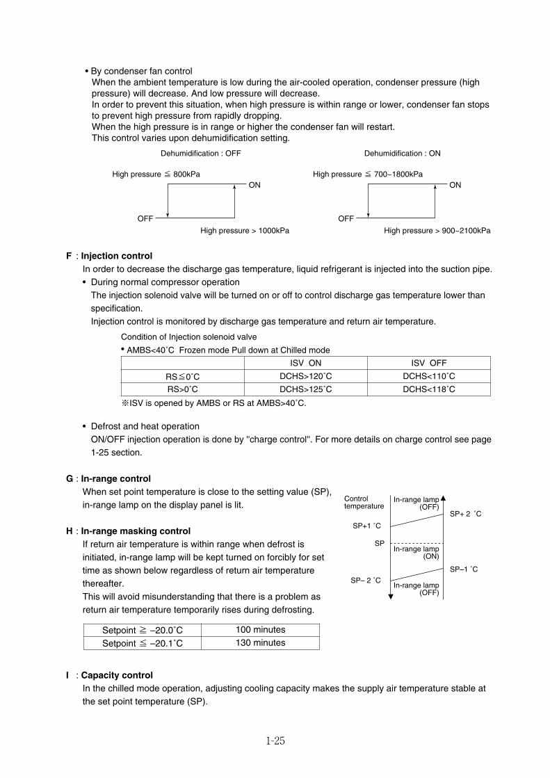
• By condenser fan controlWhen the ambient temperature is low during the air-cooled operation, condenser pressure (highpressure) will decrease. And low pressure will decrease.In order to prevent this situation, when high pressure is within range or lower, condenser fan stopsto prevent high pressure from rapidly dropping.When the high pressure is in range or higher the condenser fan will restart.This control varies upon dehumidification setting.
F : Injection controlIn order to decrease the discharge gas temperature, liquid refrigerant is injected into the suction pipe.• During normal compressor operation
The injection solenoid valve will be turned on or off to control discharge gas temperature lower thanspecification.Injection control is monitored by discharge gas temperature and return air temperature.
• Defrost and heat operationON/OFF injection operation is done by ''charge control''. For more details on charge control see page1-25 section.
G : In-range controlWhen set point temperature is close to the setting value (SP),in-range lamp on the display panel is lit.
H : In-range masking controlIf return air temperature is within range when defrost isinitiated, in-range lamp will be kept turned on forcibly for settime as shown below regardless of return air temperaturethereafter.This will avoid misunderstanding that there is a problem asreturn air temperature temporarily rises during defrosting.
I : Capacity controlIn the chilled mode operation, adjusting cooling capacity makes the supply air temperature stable atthe set point temperature (SP).
ON
OFF
High pressure > 1000kPa
High pressure ≦ 800kPa
Dehumidification : OFF Dehumidification : ON
ON
OFF
High pressure > 900~2100kPa
High pressure ≦ 700~1800kPa
Controltemperature
SP+1 ˚C
SP
SP– 2 ˚C
SP+ 2 ˚C
SP–1 ˚C
In-range lamp(OFF)
In-range lamp(OFF)
In-range lamp(ON)
Setpoint ≧ –20.0˚C 100 minutes
Setpoint ≦ –20.1˚C 130 minutes
Condition of Injection solenoid valve
ISV ON
RS>0˚C DCHS>125˚C DCHS<118˚C
※ISV is opened by AMBS or RS at AMBS>40˚C.
ISV OFF
RS≦0˚C DCHS>120˚C DCHS<110˚C
• AMBS<40˚C Frozen mode Pull down at Chilled mode
01_16-26_LXE10E100以降_E.qxd 15.3.5 11:32 AM ページ 1-25
1-26
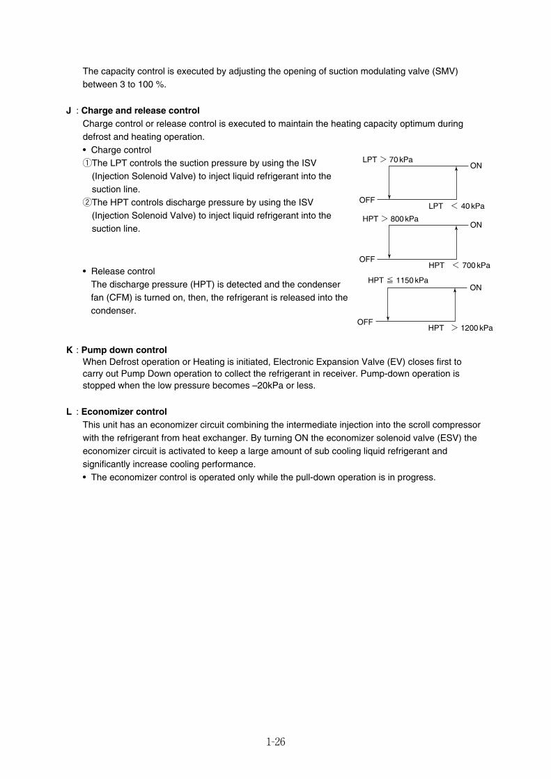
The capacity control is executed by adjusting the opening of suction modulating valve (SMV)between 3 to 100 %.
J : Charge and release controlCharge control or release control is executed to maintain the heating capacity optimum duringdefrost and heating operation.• Charge controlqThe LPT controls the suction pressure by using the ISV
(Injection Solenoid Valve) to inject liquid refrigerant into thesuction line.
wThe HPT controls discharge pressure by using the ISV(Injection Solenoid Valve) to inject liquid refrigerant into thesuction line.
• Release controlThe discharge pressure (HPT) is detected and the condenserfan (CFM) is turned on, then, the refrigerant is released into thecondenser.
K : Pump down controlWhen Defrost operation or Heating is initiated, Electronic Expansion Valve (EV) closes first tocarry out Pump Down operation to collect the refrigerant in receiver. Pump-down operation isstopped when the low pressure becomes –20kPa or less.
L : Economizer controlThis unit has an economizer circuit combining the intermediate injection into the scroll compressorwith the refrigerant from heat exchanger. By turning ON the economizer solenoid valve (ESV) theeconomizer circuit is activated to keep a large amount of sub cooling liquid refrigerant andsignificantly increase cooling performance.• The economizer control is operated only while the pull-down operation is in progress.
HPT > 1200 kPa
HPT ≦ 1150 kPaON
OFF
LPT < 40 kPa
LPT > 70 kPaON
OFF
HPT < 700 kPa
HPT > 800 kPaON
OFF
01_16-26_LXE10E100以降_E.qxd 15.3.5 11:32 AM ページ 1-26
2-1
2. ELECTRONIC CONTROLLER
2.1 Electronic controller basic operation
2.1.1 Control panel
Name and function of each component
q
ty
u
i
w
e
r
o
!0
Sheet key
LED (Light Emitting Diode)
LCD (Liquid Crystal Display)3
1
2
– 1 2 – 1 0 – 8 – 6 – 4 – 2
– 2– 3– 4– 5– 6 – 1
S P – 5
O V E R
2
I N R A N G E
H O U R S
D A Y S
1
U N D E R
A L A R MR . H .
S U P P L YR E T U R N ˚C / ˚F
%R H
D E F R O S T I N R A N G E D E H U M I DC O M P .
˚C
˚C
S P + 5
D E C O SD A I K I N E L E C T R O N I C C O N T A I N E R O P E R A T I O N S Y S T E M Ⅲ
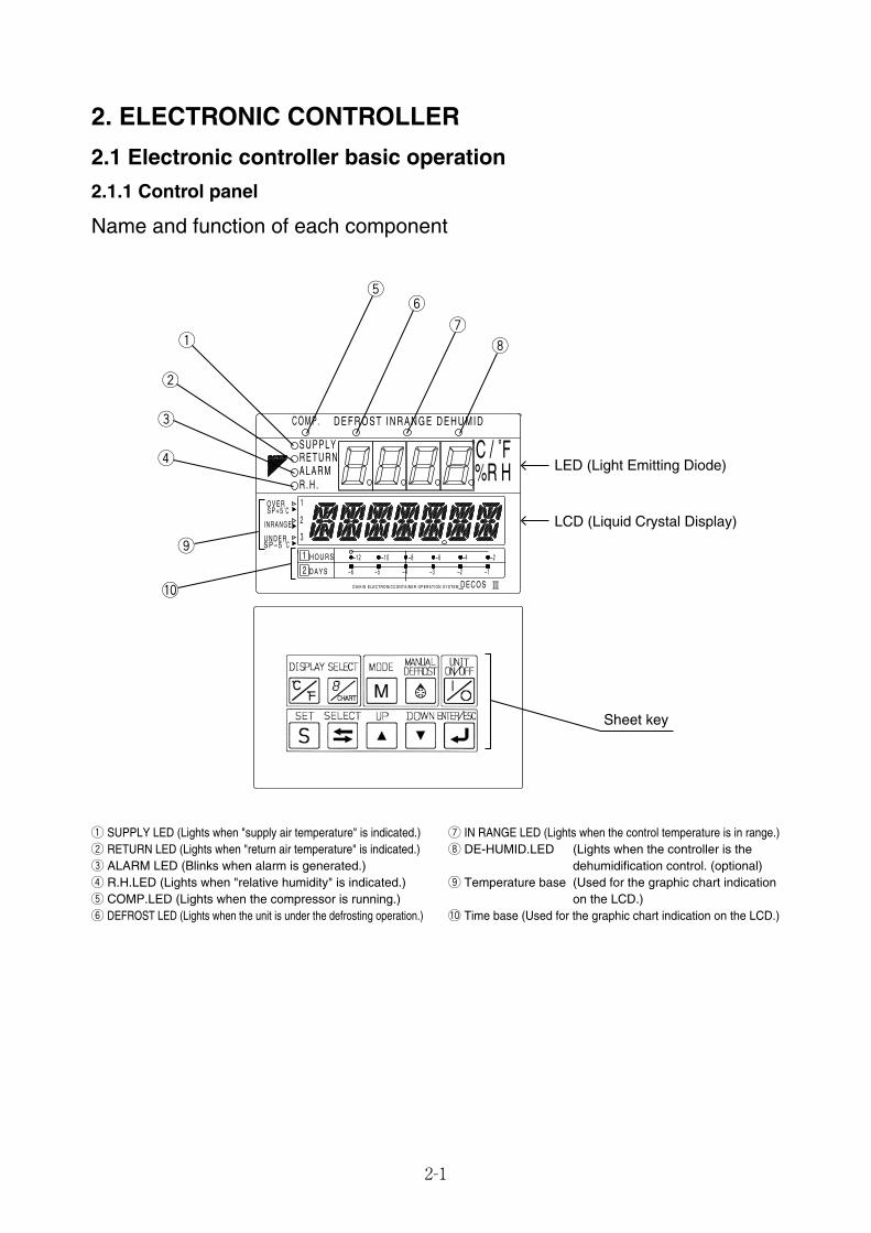
q SUPPLY LED (Lights when "supply air temperature" is indicated.)w RETURN LED (Lights when "return air temperature" is indicated.)e ALARM LED (Blinks when alarm is generated.)r R.H.LED (Lights when "relative humidity" is indicated.)t COMP.LED (Lights when the compressor is running.)y DEFROST LED (Lights when the unit is under the defrosting operation.)
u IN RANGE LED (Lights when the control temperature is in range.)i DE-HUMID.LED (Lights when the controller is the
dehumidification control. (optional)o Temperature base (Used for the graphic chart indication
on the LCD.)!0 Time base (Used for the graphic chart indication on the LCD.)
02_01-15_LXE10E100以降_E.qxd 15.3.4 11:09 AM ページ 2-1
2-2
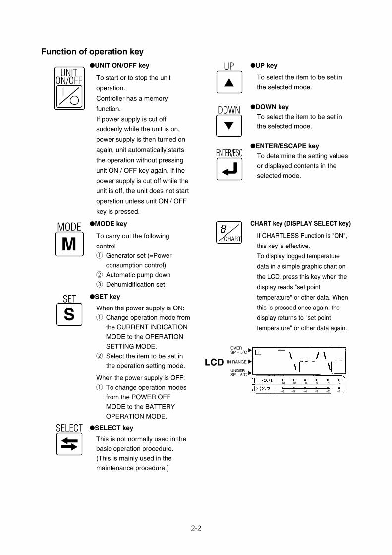
●UP key
To select the item to be set in
the selected mode.
●DOWN key
To select the item to be set in
the selected mode.
●ENTER/ESCAPE key
To determine the setting values
or displayed contents in the
selected mode.
CHART key (DISPLAY SELECT key)
If CHARTLESS Function is "ON",
this key is effective.
To display logged temperature
data in a simple graphic chart on
the LCD, press this key when the
display reads "set point
temperature" or other data. When
this is pressed once again, the
display returns to "set point
temperature" or other data again.
●UNIT ON/OFF key
To start or to stop the unit
operation.
Controller has a memory
function.
If power supply is cut off
suddenly while the unit is on,
power supply is then turned on
again, unit automatically starts
the operation without pressing
unit ON / OFF key again. If the
power supply is cut off while the
unit is off, the unit does not start
operation unless unit ON / OFF
key is pressed.
●MODE key
To carry out the following
controlq Generator set (=Power
consumption control)w Automatic pump downe Dehumidification set
●SET key
When the power supply is ON:q Change operation mode from
the CURRENT INDICATIONMODE to the OPERATIONSETTING MODE.
w Select the item to be set inthe operation setting mode.
When the power supply is OFF:q To change operation modes
from the POWER OFFMODE to the BATTERYOPERATION MODE.
●SELECT key
This is not normally used in thebasic operation procedure.(This is mainly used in themaintenance procedure.)
Function of operation key
UP
SET
S
DOWN
ENTER/ESC
SELECT
CHART
SELECT
UNITON/OFF
MODE
M
OVERSP + 5˚C
UNDERSP – 5˚C
IN RANGE
–12 –10 –8 –6 –4 –2
–6 –5 –4 –3 –2 –1
LCD
02_01-15_LXE10E100以降_E.qxd 15.3.4 11:09 AM ページ 2-2

2-3
qPress the MANUAL DEFROST key.
wSelect "ON" indicated on the LED display using the key or the
key, and press the key to determine the setting, then the
defrost operation starts.
MANUALDEFROST
MANUALDEFROST
q Indicates the temperature data required to be converted into "˚F"
on the LED or LCD.
w Press the key, then the temperature data displayed in "˚C"
is converted into "˚F" for one minute.
※ If any other key is pressed during the "˚F" indication, the display
switches to "˚C".
DISPLAYC̊
F̊
DISPLAYC̊
F̊
LED
LCD
「℃」display 「°F」display
Manual defrost operation
02_01-15_LXE10E100以降_E.qxd 15.3.4 11:09 AM ページ 2-3
2-4
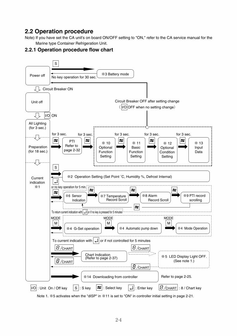
2.2 Operation procedureNote) If you have set the CA unit's on board ON/OFF setting to "ON," refer to the CA service manual for the
Marine type Container Refrigeration Unit.
2.2.1 Operation procedure flow chart
S
S
SI/O : Unit On / Off key : S key : Select key : Enter key : 8 / Chart key
CHART
CHART
CHART
CHART
CHART
M
MODE
M
MODE
M
MODE
I/O ON
Power off
Unit off
All Lighting(for 3 sec.)
Preparation(for 18 sec.)
Currentindication※1
No key operation for 30 sec.
Circuit Breaker ON
※3 Battery mode
for 3 sec.
※2 Operation Setting (Set Point ˚C, Humidity %, Defrost Internal)
※6 Sensor Indication
Chart Indication(Refer to page 2-37)
※14 Downloading from controller
※5 LED Display Light OFF.(See note 1.)
※7 TemperatureRecord Scroll
※8 AlarmRecord Scroll
※9 PTI record scrolling
or no key operation for 5 min.
To return current indication with or if no key is pressed for 5 minutes
To current indication with or if not controlled for 5 minutes
※4 G-Set operation ※4 Automatic pump down
PTIRefer to
page 2-32
Note 1. ※5 activates when the "dISP" in ※11 is set to "ON" in controller initial setting in page 2-21.
Refer to page 2-25.
I/O
for 3 sec.
Circuit Breaker OFF after setting change
( OFF when no setting change)
for 3 sec. for 3 sec. for 3 sec.
※ 10OptionalFunctionSetting
※ 11Basic
FunctionSetting
※ 12OptionalConditionSetting
※ 13InputData
※4 Mode Operation
02_01-15_LXE10E100以降_E.qxd 15.3.4 11:09 AM ページ 2-4
2-5
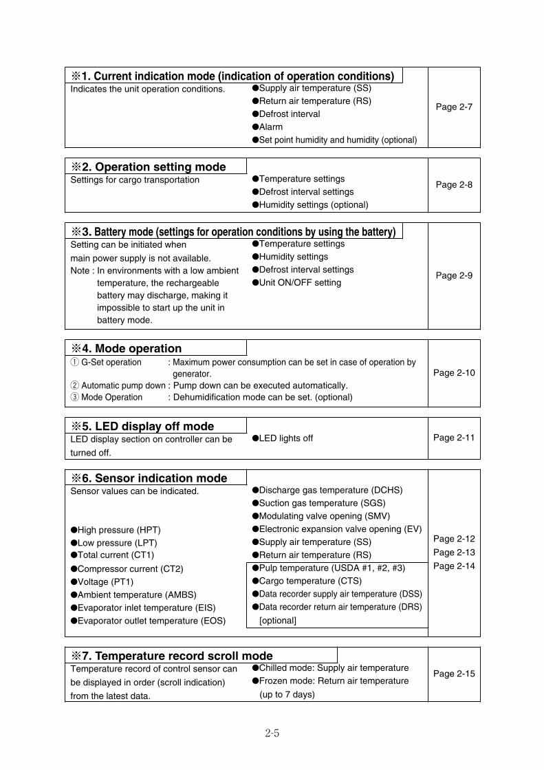
※1. Current indication mode (indication of operation conditions)
Page 2-7
Indicates the unit operation conditions. ●Supply air temperature (SS)●Return air temperature (RS)●Defrost interval●Alarm●Set point humidity and humidity (optional)
※2. Operation setting modePage 2-8Settings for cargo transportation ●Temperature settings
●Defrost interval settings●Humidity settings (optional)
※3. Battery mode (settings for operation conditions by using the battery)
Page 2-9
Setting can be initiated when
main power supply is not available.Note : In environments with a low ambient
temperature, the rechargeablebattery may discharge, making itimpossible to start up the unit inbattery mode.
●Temperature settings●Humidity settings●Defrost interval settings
※4. Mode operation
Page 2-10q G-Set operation : Maximum power consumption can be set in case of operation by
generator.w Automatic pump down : Pump down can be executed automatically.e Mode Operation : Dehumidification mode can be set. (optional)
※5. LED display off modePage 2-11LED display section on controller can be
turned off.
●LED lights off
●Return air temperature (RS)●Pulp temperature (USDA #1, #2, #3)●Cargo temperature (CTS)●Data recorder supply air temperature (DSS)●Data recorder return air temperature (DRS)
※6. Sensor indication mode
Page 2-12
Page 2-13
Page 2-14
Sensor values can be indicated. ●Discharge gas temperature (DCHS)●Suction gas temperature (SGS)●Modulating valve opening (SMV)●Electronic expansion valve opening (EV)●Supply air temperature (SS)
●High pressure (HPT)●Low pressure (LPT)●Total current (CT1)
●Compressor current (CT2)●Voltage (PT1)●Ambient temperature (AMBS)●Evaporator inlet temperature (EIS)
※7. Temperature record scroll modePage 2-15Temperature record of control sensor can
be displayed in order (scroll indication)
from the latest data.
●Chilled mode: Supply air temperature
(up to 7 days)
●Frozen mode: Return air temperature
●Evaporator outlet temperature (EOS) [optional]
●Unit ON/OFF setting
02_01-15_LXE10E100以降_E.qxd 15.3.4 11:09 AM ページ 2-5
2-6
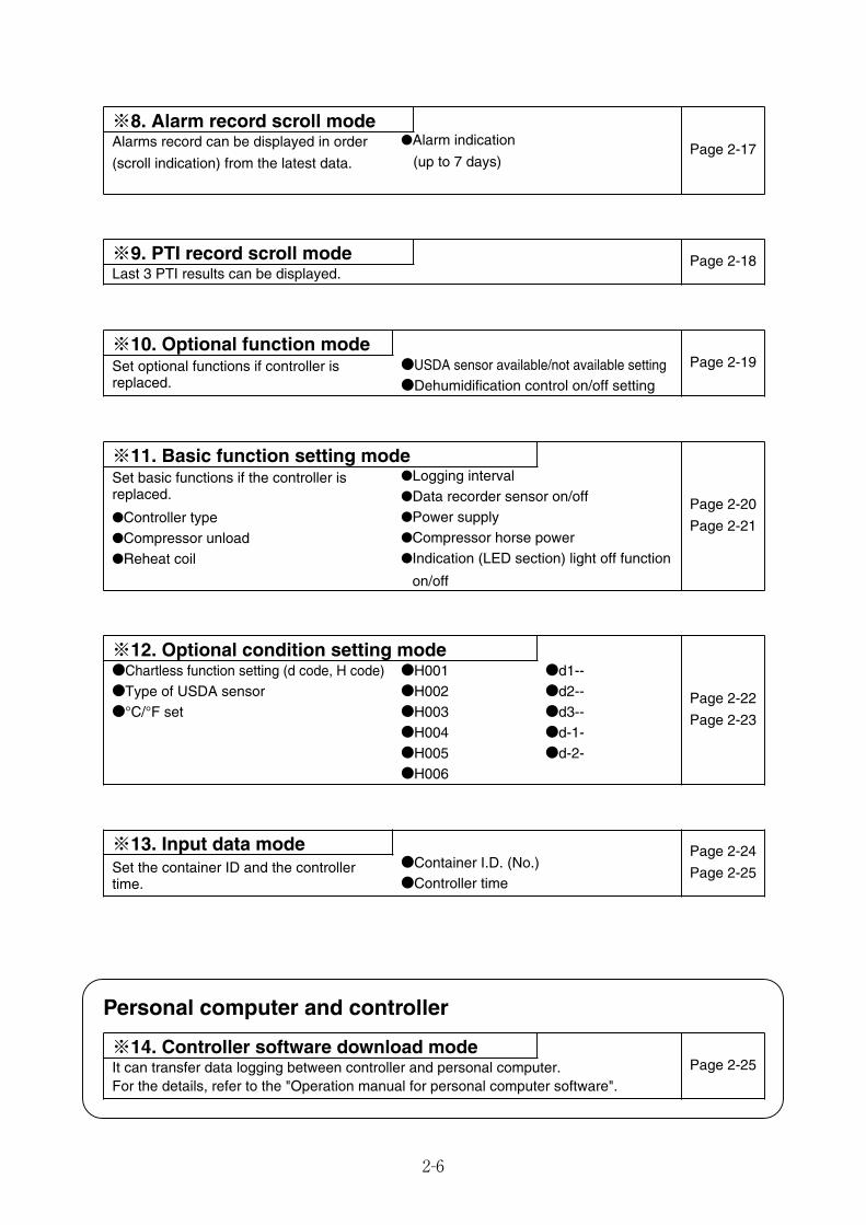
※8. Alarm record scroll modePage 2-17Alarms record can be displayed in order
(scroll indication) from the latest data.
●Alarm indication
(up to 7 days)
※9. PTI record scroll mode Page 2-18Last 3 PTI results can be displayed.
※10. Optional function modePage 2-19Set optional functions if controller is
replaced.●USDA sensor available/not available setting●Dehumidification control on/off setting
※11. Basic function setting mode
Page 2-20
Page 2-21
Set basic functions if the controller isreplaced.
●Logging interval
●Indication (LED section) light off function
on/off
●Data recorder sensor on/off●Power supply
※12. Optional condition setting mode
Page 2-22
Page 2-23
●Chartless function setting (d code, H code) ●H001
●H006
●H002
●H005
●H003●H004
※13. Input data mode Page 2-24
Page 2-25Set the container ID and the controllertime.
●Container I.D. (No.)●Controller time
Personal computer and controller
It can transfer data logging between controller and personal computer.For the details, refer to the "Operation manual for personal computer software".
※14. Controller software download modePage 2-25
●d1--●d2--●d3--●d-1-●d-2-
●Controller type
●Reheat coil●Compressor unload ●Compressor horse power
●Type of USDA sensor●°C/°F set
02_01-15_LXE10E100以降_E.qxd 15.3.4 11:09 AM ページ 2-6
2.2.2 Mode operation procedure
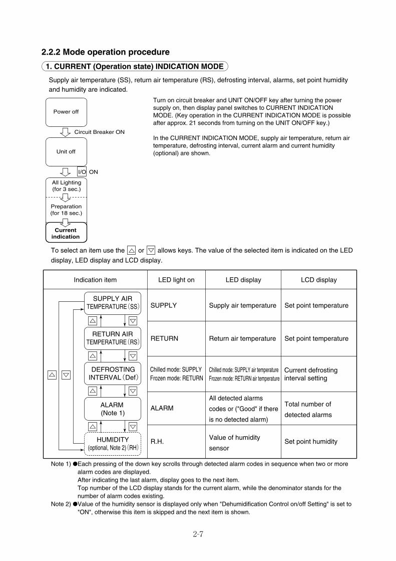
1. CURRENT (Operation state) INDICATION MODE
Supply air temperature (SS), return air temperature (RS), defrosting interval, alarms, set point humidityand humidity are indicated.
2-7
Turn on circuit breaker and UNIT ON/OFF key after turning the powersupply on, then display panel switches to CURRENT INDICATIONMODE. (Key operation in the CURRENT INDICATION MODE is possibleafter approx. 21 seconds from turning on the UNIT ON/OFF key.)
In the CURRENT INDICATION MODE, supply air temperature, return airtemperature, defrosting interval, current alarm and current humidity(optional) are shown.
To select an item use the or allows keys. The value of the selected item is indicated on the LED
display, LED display and LCD display.
Note 1) ●Each pressing of the down key scrolls through detected alarm codes in sequence when two or morealarm codes are displayed.After indicating the last alarm, display goes to the next item.Top number of the LCD display stands for the current alarm, while the denominator stands for thenumber of alarm codes existing.
Note 2) ●Value of the humidity sensor is displayed only when "Dehumidification Control on/off Setting" is set to"ON", otherwise this item is skipped and the next item is shown.
LED light on
SUPPLY
RETURN
ALARM
R.H.
LED display
Supply air temperature
Return air temperature
All detected alarms
codes or ("Good" if there
is no detected alarm)
Value of humidity
sensor
LCD display
Set point temperature
Set point temperature
Total number of
detected alarms
Set point humidity
Indication item
Chilled mode: SUPPLYFrozen mode: RETURN
Chilled mode: SUPPLY air temperatureFrozen mode: RETURN air temperature
Current defrosting interval setting
ALARM (Note 1)
HUMIDITY (optional, Note 2)(RH)
DEFROSTING INTERVAL(Def)
SUPPLY AIR TEMPERATURE(SS)
RETURN AIR TEMPERATURE(RS)
I/O ON
Power off
Unit off
All Lighting(for 3 sec.)
Preparation(for 18 sec.)
Currentindication
Circuit Breaker ON
02_01-15_LXE10E100以降_E.qxd 15.3.4 11:09 AM ページ 2-7
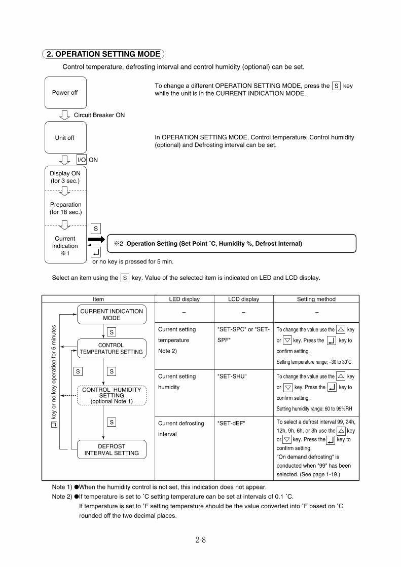
2. OPERATION SETTING MODE
Control temperature, defrosting interval and control humidity (optional) can be set.
2-8
To change a different OPERATION SETTING MODE, press the keywhile the unit is in the CURRENT INDICATION MODE.
In OPERATION SETTING MODE, Control temperature, Control humidity(optional) and Defrosting interval can be set.
S
Select an item using the key. Value of the selected item is indicated on LED and LCD display.S
Note 1) ●When the humidity control is not set, this indication does not appear.
Note 2) ●If temperature is set to ˚C setting temperature can be set at intervals of 0.1 ˚C.
If temperature is set to ˚F setting temperature should be the value converted into ˚F based on ˚C
rounded off the two decimal places.
LED display
Current setting
temperature
Note 2)
Current setting
humidity
Current defrosting
interval
LCD display
"SET-SPC" or "SET-
SPF"
"SET-SHU"
"SET-dEF"
Setting method
To change the value use the key
or key. Press the key to
confirm setting.
Setting temperature range; –30 to 30˚C.
To change the value use the key
or key. Press the key to
confirm setting.
Setting humidity range: 60 to 95%RH
To select a defrost interval 99, 24h,
12h, 9h, 6h, or 3h use the key
or key. Press the key to
confirm setting.
"On demand defrosting" is
conducted when "99" has been
selected. (See page 1-19.)
Item
– – –
key
or n
o ke
y op
erat
ion
for
5 m
inut
es
CURRENT INDICATION MODE
S
CONTROL TEMPERATURE SETTING
SS
CONTROL HUMIDITY SETTING
(optional Note 1)
S
DEFROSTINTERVAL SETTING
S
I/O ON
Power off
Unit off
Display ON(for 3 sec.)
Preparation(for 18 sec.)
Currentindication※1
Circuit Breaker ON
※2 Operation Setting (Set Point ˚C, Humidity %, Defrost Internal)
or no key is pressed for 5 min.
02_01-15_LXE10E100以降_E.qxd 15.3.4 11:09 AM ページ 2-8
2-9
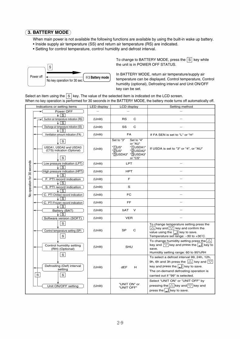
To change to BATTERY MODE, press the key whilethe unit is in POWER OFF STATUS.
In BATTERY MODE, return air temperature/supply airtemperature can be displayed. Control temperature, Controlhumidity (optional), Defrosting interval and Unit ON/OFFkey can be set.
S
Select an item using the key. The value of the selected item is indicated on the LCD screen.When no key operation is performed for 30 seconds in the BATTERY MODE, the battery mode turns off automatically off.
S
3. BATTERY MODEWhen main power is not available the following functions are available by using the built-in wake up battery.• Inside supply air temperature (SS) and return air temperature (RS) are indicated.• Setting for control temperature, control humidity and defrost interval.
S
Power offNo key operation for 30 sec.
※3 Battery mode
LED display LCD display Setting methodIndications or setting items
-
-
- - -
(Unlit) RS C
(Unlit)
(Unlit)
SS C
(Unlit) FA
- (Unlit)
- (Unlit) F
- (Unlit) HPT
LPT
- (Unlit) S
- (Unlit) FC
- (Unlit) FF
If USDA is set to "3" or "4", or "AU"
If FA SEN is set to "L" or "H"
Set to "3" Set to "4" or "AU"" 1 US" " 1 USDA1"" 2 US" " 2 USDA2"" 3 USDA3" " 3 USDA3" or "CS"
S
S
S
S
S
S
S
S
S
S
S
S
Power OFF
Suction air temperature indication (RS)
Discharge air temperature indication (SS)
Ventilation amount indication (FA)
USDA1, USDA2 and USDA3 (CTS) indication (Optional)
Low pressure indication (LPT)
High pressure indication (HPT)
F. PTI record indication
S. PTI record indication
C. PTI Chilled record indication
C. PTI Frozen record indication
No
oper
atio
n fo
r 30
seco
nds
(Unlit)
(Unlit)
(Unlit)
(Unlit)
- (Unlit) bAT V
- (Unlit) VER
SP C
SHU
dEF H
S
S
Control humidity setting (RH) (Optional)
S
SS
Unit ON/OFF setting
Battery (BAT)
Software version (SOFT)
Control temperature setting (SP)
Defrosting (Def) interval setting
To change temperature setting press the key and key and confirm the value using the key to save.Temperature set range: –30 to +30˚C
To change humidity setting press the key and key and press the key to save.Humidity setting range: 60 to 95%RH
To select a defrost interval 99, 24h, 12h,
9h, 6h and 3h press the key and
key and press the key to save.
The on-demand defrosting operation is
carried out if "99" is selected.
Select "UNIT ON" or "UNIT OFF" by
pressing the key and key and
press the key to save.
"UNIT ON" or "UNIT OFF"
02_01-15_LXE10E100以降_E.qxd 15.3.4 11:09 AM ページ 2-9
2-10
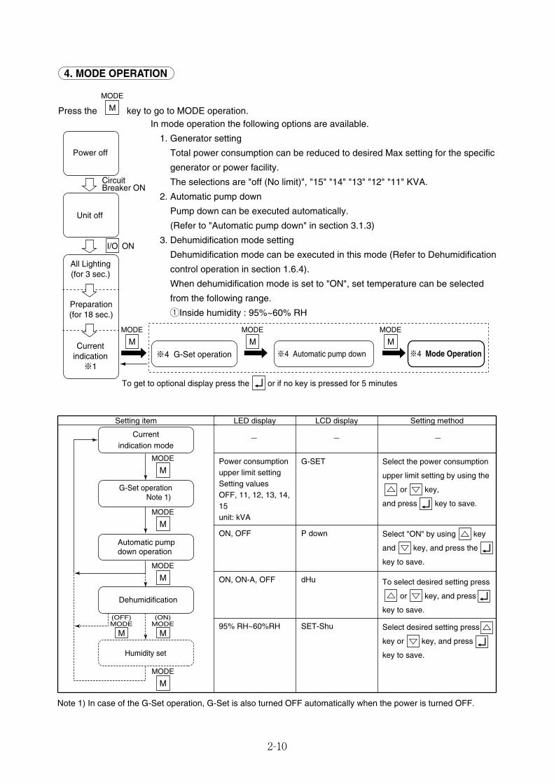
4. MODE OPERATION
Press the key to go to MODE operation.M
MODE
I/O ON
MODE
M
MODE
M
MODE
M
Power off
Unit off
All Lighting(for 3 sec.)
Preparation(for 18 sec.)
Currentindication※1
Circuit Breaker ON
※4 G-Set operation ※4 Automatic pump down ※4 Mode Operation
To get to optional display press the or if no key is pressed for 5 minutes
LED display Setting methodSetting item
- - -
Power consumption upper limit settingSetting valuesOFF, 11, 12, 13, 14, 15unit: kVA
Select the power consumption
upper limit setting by using the
or key,
and press key to save.
Select "ON" by using key
and key, and press the
key to save.
To select desired setting press
or key, and press
key to save.
Select desired setting press
key or key, and press
key to save.
ON, OFF P down
ON, ON-A, OFF dHu
95% RH~60%RH SET-Shu
LCD display
G-SET
Note 1) In case of the G-Set operation, G-Set is also turned OFF automatically when the power is turned OFF.
Currentindication mode
M
MODE
M
MODE
M
MODE
M
MODE
M
(ON)MODE
M
(OFF)MODE
G-Set operation Note 1)
Automatic pumpdown operation
Dehumidification
Humidity set
In mode operation the following options are available.
1. Generator setting
Total power consumption can be reduced to desired Max setting for the specific
generator or power facility.
The selections are "off (No limit)", "15" "14" "13" "12" "11" KVA.
2. Automatic pump down
Pump down can be executed automatically.
(Refer to "Automatic pump down" in section 3.1.3)
3. Dehumidification mode setting
Dehumidification mode can be executed in this mode (Refer to Dehumidification
control operation in section 1.6.4).
When dehumidification mode is set to "ON", set temperature can be selected
from the following range.
qInside humidity : 95%~60% RH
02_01-15_LXE10E100以降_E.qxd 15.3.4 11:09 AM ページ 2-10
2-11
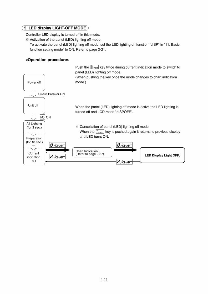
5. LED display LIGHT-OFF MODE
Controller LED display is turned off in this mode.※ Activation of the panel (LED) lighting off mode.
To activate the panel (LED) lighting off mode, set the LED lighting off function "dISP" in "11. Basicfunction setting mode" to ON. Refer to page 2-21.
<Operation procedure>
Push the key twice during current indication mode to switch topanel (LED) lighting off mode.(When pushing the key once the mode changes to chart indicationmode.)
When the panel (LED) lighting off mode is active the LED lighting isturned off and LCD reads "dISPOFF".
※ Cancellation of panel (LED) lighting off mode.When the key is pushed again it returns to previous displayand LED turns ON.
0/CHART
0/CHART
I/O ON
CHART
CHART
CHART
CHART
Power off
Unit off
All Lighting(for 3 sec.)
Preparation(for 18 sec.)
Currentindication※1
Circuit Breaker ON
Chart Indication(Refer to page 2-37) LED Display Light OFF.
02_01-15_LXE10E100以降_E.qxd 15.3.4 11:09 AM ページ 2-11
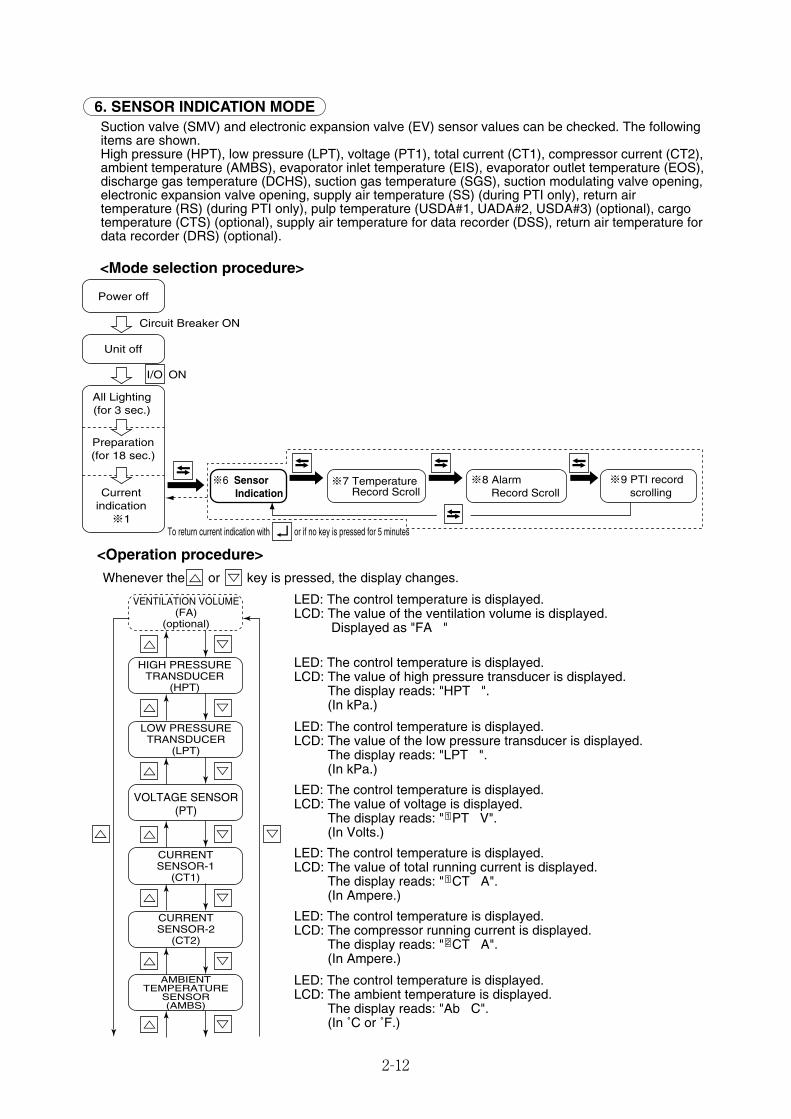
2-12
6. SENSOR INDICATION MODESuction valve (SMV) and electronic expansion valve (EV) sensor values can be checked. The followingitems are shown.High pressure (HPT), low pressure (LPT), voltage (PT1), total current (CT1), compressor current (CT2),ambient temperature (AMBS), evaporator inlet temperature (EIS), evaporator outlet temperature (EOS),discharge gas temperature (DCHS), suction gas temperature (SGS), suction modulating valve opening,electronic expansion valve opening, supply air temperature (SS) (during PTI only), return airtemperature (RS) (during PTI only), pulp temperature (USDA#1, UADA#2, USDA#3) (optional), cargotemperature (CTS) (optional), supply air temperature for data recorder (DSS), return air temperature fordata recorder (DRS) (optional).
<Mode selection procedure>
<Operation procedure>
Whenever the or key is pressed, the display changes.
LED: The control temperature is displayed.LCD: The value of the ventilation volume is displayed.
Displayed as "FA "
LED: The control temperature is displayed.LCD: The value of high pressure transducer is displayed.
The display reads: "HPT ".(In kPa.)
LED: The control temperature is displayed.LCD: The value of the low pressure transducer is displayed.
The display reads: "LPT ".(In kPa.)
LED: The control temperature is displayed.LCD: The value of voltage is displayed.
The display reads: " PT V".(In Volts.)
LED: The control temperature is displayed.LCD: The value of total running current is displayed.
The display reads: " CT A".(In Ampere.)
LED: The control temperature is displayed.LCD: The compressor running current is displayed.
The display reads: " CT A".(In Ampere.)
LED: The control temperature is displayed.LCD: The ambient temperature is displayed.
The display reads: "Ab C".(In ˚C or ˚F.)
2
1
1
I/O ON
Power off
Unit off
All Lighting(for 3 sec.)
Preparation(for 18 sec.)
Currentindication※1
Circuit Breaker ON
※6 Sensor Indication
※7 TemperatureRecord Scroll
※8 AlarmRecord Scroll
To return current indication with or if no key is pressed for 5 minutes
※9 PTI record scrolling
HIGH PRESSURETRANSDUCER
(HPT)
VENTILATION VOLUME(FA)
(optional)
LOW PRESSURETRANSDUCER
(LPT)
CURRENTSENSOR-1
(CT1)
VOLTAGE SENSOR(PT)
CURRENTSENSOR-2
(CT2)
AMBIENTTEMPERATURE
SENSOR(AMBS)
02_01-15_LXE10E100以降_E.qxd 15.3.4 11:09 AM ページ 2-12
2-13
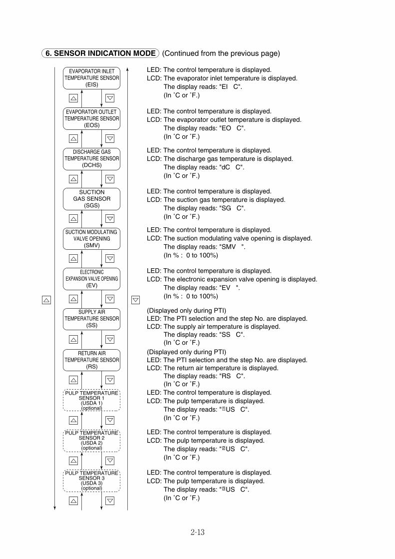
6. SENSOR INDICATION MODE (Continued from the previous page)
LED: The control temperature is displayed.LCD: The evaporator inlet temperature is displayed.
The display reads: "EI C".(In ˚C or ˚F.)
LED: The control temperature is displayed.LCD: The evaporator outlet temperature is displayed.
The display reads: "EO C".(In ˚C or ˚F.)
LED: The control temperature is displayed.LCD: The discharge gas temperature is displayed.
The display reads: "dC C".(In ˚C or ˚F.)
LED: The control temperature is displayed.LCD: The suction gas temperature is displayed.
The display reads: "SG C".(In ˚C or ˚F.)
LED: The control temperature is displayed.LCD: The suction modulating valve opening is displayed.
The display reads: "SMV ".(In % : 0 to 100%)
LED: The control temperature is displayed.LCD: The electronic expansion valve opening is displayed.
The display reads: "EV ".(In % : 0 to 100%)
(Displayed only during PTI)LED: The PTI selection and the step No. are displayed.LCD: The supply air temperature is displayed.
The display reads: "SS C".(In ˚C or ˚F.)
(Displayed only during PTI)LED: The PTI selection and the step No. are displayed.LCD: The return air temperature is displayed.
The display reads: "RS C".(In ˚C or ˚F.)
LED: The control temperature is displayed.LCD: The pulp temperature is displayed.
The display reads: " US C".(In ˚C or ˚F.)
LED: The control temperature is displayed.LCD: The pulp temperature is displayed.
The display reads: " US C".(In ˚C or ˚F.)
LED: The control temperature is displayed.LCD: The pulp temperature is displayed.
The display reads: " US C".(In ˚C or ˚F.)
3
2
1
SUPPLY AIRTEMPERATURE SENSOR
(SS)
EVAPORATOR INLETTEMPERATURE SENSOR
(EIS)
EVAPORATOR OUTLET TEMPERATURE SENSOR
(EOS)
DISCHARGE GASTEMPERATURE SENSOR
(DCHS)
SUCTIONGAS SENSOR
(SGS)
SUCTION MODULATING VALVE OPENING
(SMV)
ELECTRONICEXPANSION VALVE OPENING
(EV)
RETURN AIRTEMPERATURE SENSOR
(RS)
PULP TEMPERATURESENSOR 1(USDA 1)(optional)
PULP TEMPERATURESENSOR 2(USDA 2)(optional)
PULP TEMPERATURESENSOR 3(USDA 3)(optional)
02_01-15_LXE10E100以降_E.qxd 15.3.4 11:09 AM ページ 2-13
2-14
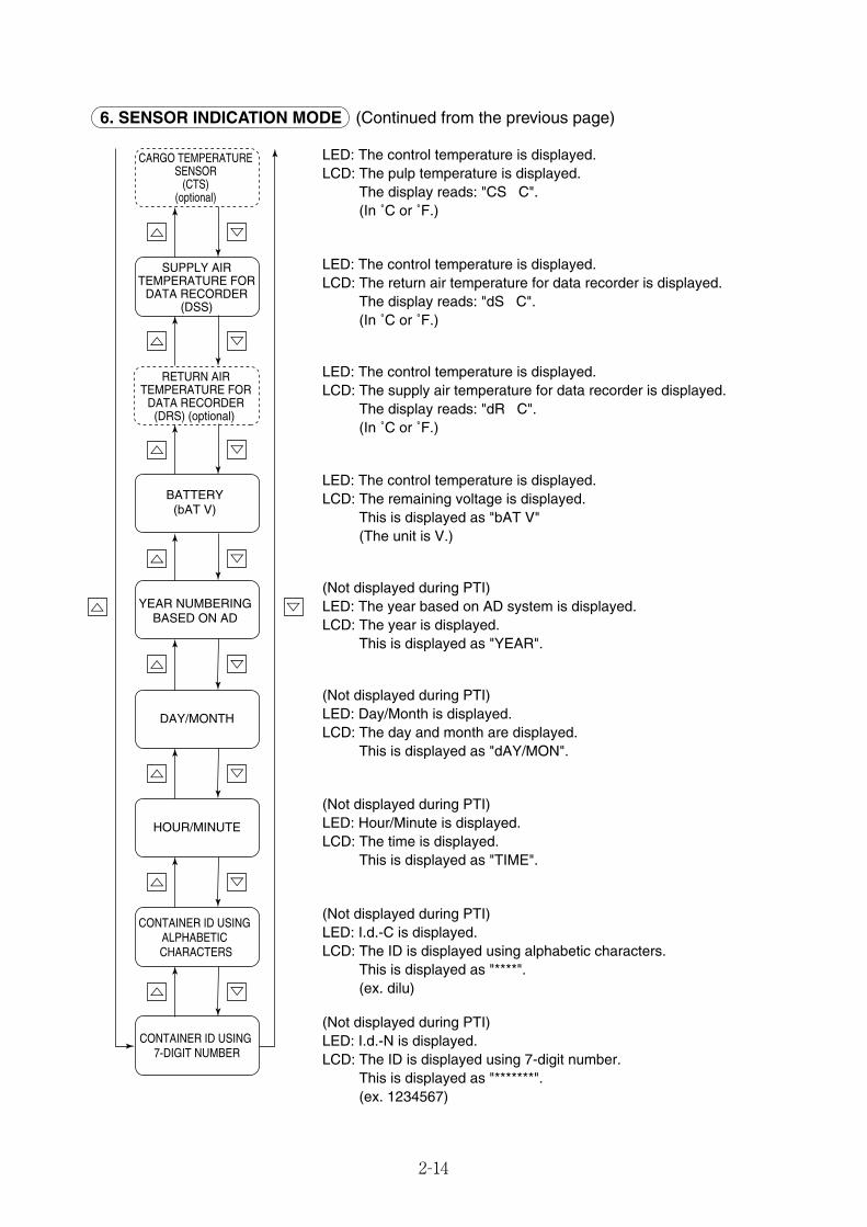
LED: The control temperature is displayed.LCD: The pulp temperature is displayed.
The display reads: "CS C".(In ˚C or ˚F.)
LED: The control temperature is displayed.LCD: The return air temperature for data recorder is displayed.
The display reads: "dS C".(In ˚C or ˚F.)
LED: The control temperature is displayed.LCD: The supply air temperature for data recorder is displayed.
The display reads: "dR C".(In ˚C or ˚F.)
LED: The control temperature is displayed.LCD: The remaining voltage is displayed.
This is displayed as "bAT V"(The unit is V.)
(Not displayed during PTI)LED: The year based on AD system is displayed.LCD: The year is displayed.
This is displayed as "YEAR".
(Not displayed during PTI)LED: Day/Month is displayed.LCD: The day and month are displayed.
This is displayed as "dAY/MON".
(Not displayed during PTI)LED: Hour/Minute is displayed.LCD: The time is displayed.
This is displayed as "TIME".
(Not displayed during PTI)LED: I.d.-C is displayed.LCD: The ID is displayed using alphabetic characters.
This is displayed as "****".(ex. dilu)
(Not displayed during PTI)LED: I.d.-N is displayed.LCD: The ID is displayed using 7-digit number.
This is displayed as "*******".(ex. 1234567)
6. SENSOR INDICATION MODE (Continued from the previous page)
CARGO TEMPERATURESENSOR
(CTS)(optional)
SUPPLY AIRTEMPERATURE FOR
DATA RECORDER(DSS)
RETURN AIRTEMPERATURE FOR
DATA RECORDER(DRS) (optional)
BATTERY(bAT V)
YEAR NUMBERINGBASED ON AD
DAY/MONTH
HOUR/MINUTE
CONTAINER ID USING ALPHABETIC CHARACTERS
CONTAINER ID USING 7-DIGIT NUMBER
02_01-15_LXE10E100以降_E.qxd 15.3.4 11:09 AM ページ 2-14
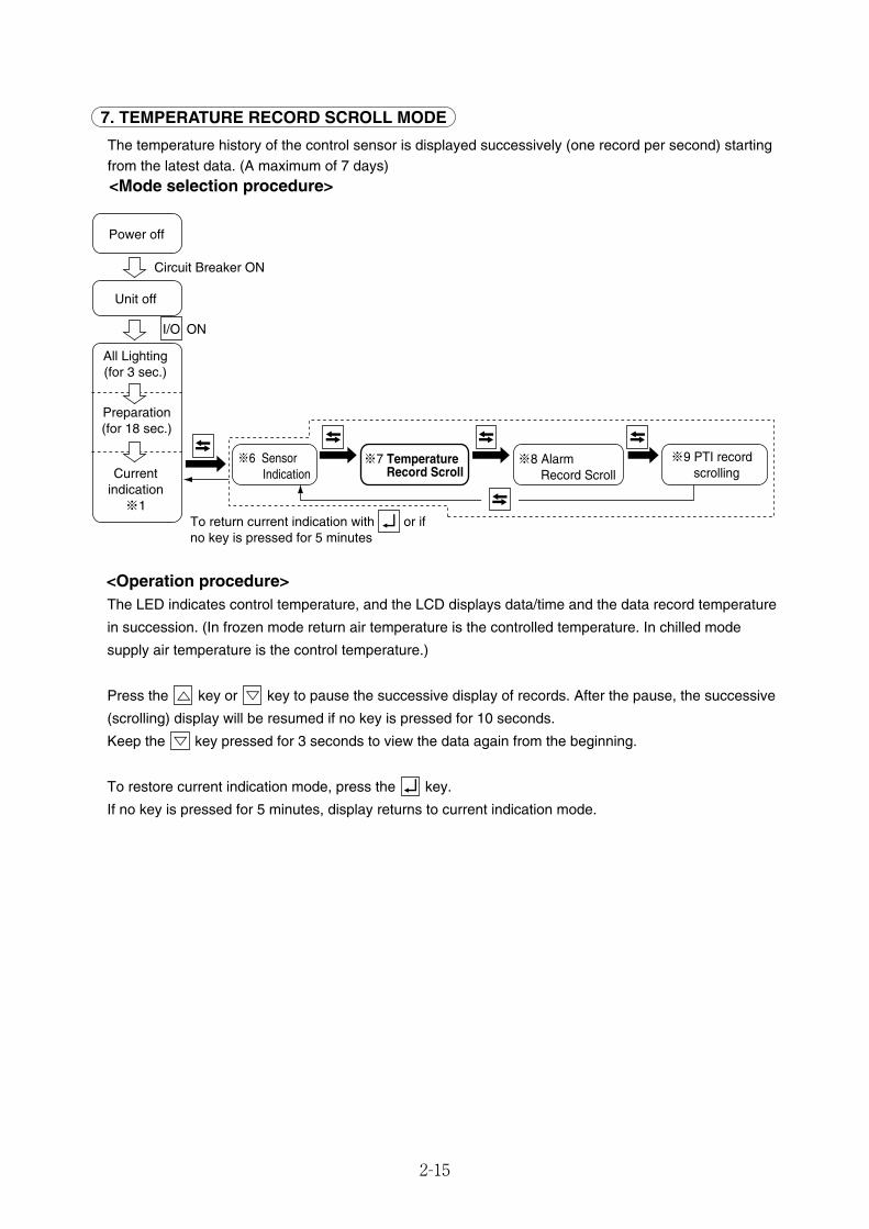
2-15
7. TEMPERATURE RECORD SCROLL MODE
The temperature history of the control sensor is displayed successively (one record per second) startingfrom the latest data. (A maximum of 7 days)<Mode selection procedure>
<Operation procedure>The LED indicates control temperature, and the LCD displays data/time and the data record temperature
in succession. (In frozen mode return air temperature is the controlled temperature. In chilled mode
supply air temperature is the control temperature.)
Press the key or key to pause the successive display of records. After the pause, the successive
(scrolling) display will be resumed if no key is pressed for 10 seconds.
Keep the key pressed for 3 seconds to view the data again from the beginning.
To restore current indication mode, press the key.
If no key is pressed for 5 minutes, display returns to current indication mode.
I/O ON
Power off
Unit off
All Lighting(for 3 sec.)
Preparation(for 18 sec.)
Currentindication※1
Circuit Breaker ON
※6 Sensor Indication
※7 TemperatureRecord Scroll
※8 AlarmRecord Scroll
※9 PTI record scrolling
To return current indication with or if no key is pressed for 5 minutes
02_01-15_LXE10E100以降_E.qxd 15.3.4 11:09 AM ページ 2-15
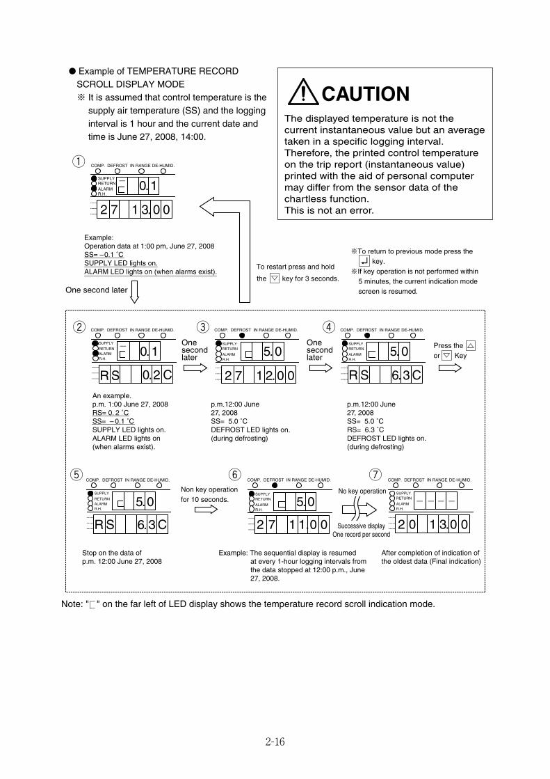
2-16
● Example of TEMPERATURE RECORDSCROLL DISPLAY MODE※ It is assumed that control temperature is the
supply air temperature (SS) and the logginginterval is 1 hour and the current date andtime is June 27, 2008, 14:00.
COMP. DEFROST IN RANGE DE-HUMID.
--------------- 2 7 3.1
SUPPLYRETURNALARMR.H.
0.1-
0 0
--------------- 0. C2
SUPPLY
RETURNALARMR.H.
0. 1-
R S .--------------- 6. C3
SUPPLYRETURN
ALARMR.H.
R S.---------------
SUPPLYRETURN
ALARMR.H.
5. 05.0
2.2 7 1 0 0
---------------
SUPPLYRETURN
ALARMR.H.
2 0 3.1
- ---
0 0---------------
SUPPLYRETURN
ALARMR.H.
5.0
2 7 1.1 0 0---------------
SUPPLY
RETURNALARMR.H.
COMP. DEFROST IN RANGE DE-HUMID. COMP. DEFROST IN RANGE DE-HUMID. COMP. DEFROST IN RANGE DE-HUMID.
COMP. DEFROST IN RANGE DE-HUMID. COMP. DEFROST IN RANGE DE-HUMID. COMP. DEFROST IN RANGE DE-HUMID.
5.0
6. C3R S
the key for 3 seconds.
To restart press and hold
One second later
Onesecondlater
Onesecondlater
Press the or Key
Non key operationfor 10 seconds.
Example: Operation data at 1:00 pm, June 27, 2008SS= –0.1 ˚CSUPPLY LED lights on.ALARM LED lights on (when alarms exist).
An example.p.m. 1:00 June 27, 2008RS= 0. 2 ˚C SS= – 0.1 ˚C SUPPLY LED lights on.ALARM LED lights on(when alarms exist).
Stop on the data ofp.m. 12:00 June 27, 2008
Example: The sequential display is resumed at every 1-hour logging intervals from the data stopped at 12:00 p.m., June 27, 2008.
After completion of indication ofthe oldest data (Final indication)
No key operation
Successive displayOne record per second
p.m. 12:00 June27, 2008 SS= 5.0 ˚C DEFROST LED lights on.(during defrosting)
p.m. 12:00 June 27, 2008SS= 5.0 ˚CRS= 6.3 ˚CDEFROST LED lights on.(during defrosting)
※To return to previous mode press the key.※If key operation is not performed within 5 minutes, the current indication mode screen is resumed.
uyt
rew
q
The displayed temperature is not thecurrent instantaneous value but an averagetaken in a specific logging interval.Therefore, the printed control temperatureon the trip report (instantaneous value)printed with the aid of personal computermay differ from the sensor data of thechartless function.This is not an error.
CAUTION
Note: " " on the far left of LED display shows the temperature record scroll indication mode.
02_16-27_LXE10E100以降_E.qxd 15.3.4 11:14 AM ページ 2-16
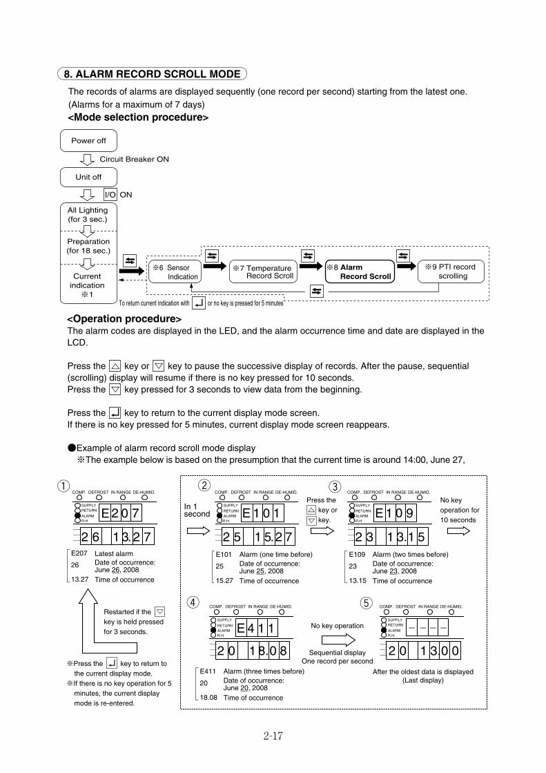
2-17
8. ALARM RECORD SCROLL MODE
The records of alarms are displayed sequently (one record per second) starting from the latest one.(Alarms for a maximum of 7 days)<Mode selection procedure>
I/O ON
Power off
Unit off
All Lighting(for 3 sec.)
Preparation(for 18 sec.)
Currentindication※1
Circuit Breaker ON
※6 Sensor Indication
※7 TemperatureRecord Scroll
※8 AlarmRecord Scroll
※9 PTI record scrolling
To return current indication with or no key is pressed for 5 minutes
<Operation procedure>The alarm codes are displayed in the LED, and the alarm occurrence time and date are displayed in theLCD.
Press the key or key to pause the successive display of records. After the pause, sequential(scrolling) display will resume if there is no key pressed for 10 seconds.Press the key pressed for 3 seconds to view data from the beginning.
Press the key to return to the current display mode screen.If there is no key pressed for 5 minutes, current display mode screen reappears.
●Example of alarm record scroll mode display※The example below is based on the presumption that the current time is around 14:00, June 27,
.
SUPPLYRETURN
ALARMR.H.
---------------
SUPPLY
RETURNALARMR.H.
---------------2 5 5.1
E 1 0 1
2 7
SUPPLY
RETURNALARMR.H.
---------------
SUPPLYRETURN
ALARMR.H.
---------------
- ---SUPPLY
RETURNALARMR.H.
---------------2 0 8.1
E 4 1 1
0 8
COMP. DEFROST IN RANGE DE-HUMID.COMP. DEFROST IN RANGE DE-HUMID.COMP. DEFROST IN RANGE DE-HUMID.
COMP. DEFROST IN RANGE DE-HUMID.
2 0 3.1 0 0
COMP. DEFROST IN RANGE DE-HUMID.
2 3 3.1
E 1 0 9
1 52 6 3.
2 0 7
2 71E207 Latest alarm
Date of occurrence: June 26, 2008Time of occurrence
26
13.27
E101 Alarm (one time before)Date of occurrence: June 25, 2008Time of occurrence
25
15.27
E411 Alarm (three times before)Date of occurrence: June 20, 2008Time of occurrence
20
18.08
E109 Alarm (two times before)Date of occurrence: June 23, 2008Time of occurrence
23
13.15
E
Restarted if the key is held pressed for 3 seconds.
In 1 second
Press the key or key.
No key operation for 10 seconds
No key operation
Sequential displayOne record per second
tr
ewq
※Press the key to return to the current display mode.※If there is no key operation for 5 minutes, the current display mode is re-entered.
After the oldest data is displayed(Last display)
02_16-27_LXE10E100以降_E.qxd 15.3.4 11:14 AM ページ 2-17
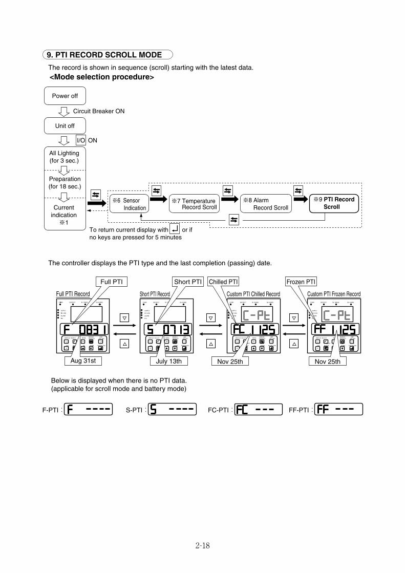
2-18
9. PTI RECORD SCROLL MODE
The record is shown in sequence (scroll) starting with the latest data. <Mode selection procedure>
The controller displays the PTI type and the last completion (passing) date.
I/O ON
Power off
Unit off
All Lighting(for 3 sec.)
Preparation(for 18 sec.)
Currentindication※1
Circuit Breaker ON
※6 Sensor Indication
※7 TemperatureRecord Scroll
※8 AlarmRecord Scroll
※9 PTI Record Scroll
To return current display with or if no keys are pressed for 5 minutes
Below is displayed when there is no PTI data.(applicable for scroll mode and battery mode)
Frozen PTI
Nov 25thNov 25thJuly 13thAug 31st
Chilled PTIShort PTIFull PTI
Full PTI Record Short PTI Record Custom PTI Chilled Record Custom PTI Frozen Record
F-PTI: S-PTI: FC-PTI: FF-PTI:
02_16-27_LXE10E100以降_E.qxd 15.3.4 11:14 AM ページ 2-18

2-19
10. OPTIONAL FUNCTION SETTING MODE
<Key operation to enter/exit>
<Key operation in this mode>Whenever the key is pressed, the display changes.
To save the setting, turn circuit breaker OFF after changing setting.
S
I/O ON
※ 11 ※ 12 ※ 13
Power off
Unit off
All Lighting(for 3 sec.)
Preparation(for 18 sec.)
Currentindication※1
Circuit Breaker ON
for 3 sec. for 3 sec. for 3 sec. for 3 sec. for 3 sec.
I/O
Circuit Breaker OFF after setting change
( OFF when no setting changed)
OptionalFunctionSetting
BasicFunctionSetting
OptionalConditionSetting
InputData
※ 10PTIM.CHECK
LED display LCD display Setting methodIndications or setting items
OFF: USDA sensor not available
3 : 3 USDA sensors
4 : 3 USDA sensors and 1 cargo
temperature sensor
Au : To measure the temperature inside or
cargo temperature for the purposes
other than cold treatment transport,
USDA sensor can record the
temperatures ranging from -38℃ to
+40℃. Don’t use USDA sensor for
cold treatment transport because it
does not meet the USDA standards.
ON : Dehumidification operation with dehumidification sensor installed
ON-A: Dehumidification operation without dehumidification sensor
OFF : No dehumidification operationNote : Check if the dehumidification coil is
available or not available in section 2.2.2 (11. Basic function setting mode)
Make selection using the key
and key. Press the key
to save selection.
Note: "3" is set automatically if
2 USDA sensors are
connected.
Make selection using the key
and key. Press the key
to save selection.Note: The dehumidification can
be turned ON and OFF during the mode operation described in 2.2.2 (4. MODE OPERATION)
USdA
dHU
SS
USDA sensor available/not availableCargo humidity sensor available/not available
Dehumidification operation ON/OFF
02_16-27_LXE10E100以降_E.qxd 15.3.4 11:14 AM ページ 2-19
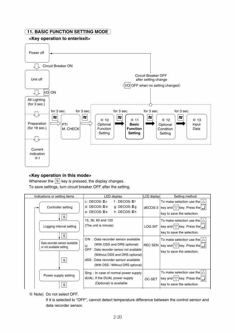
2-20
11. BASIC FUNCTION SETTING MODE
<Key operation to enter/exit>
<Key operation in this mode>Whenever the key is pressed, the display changes.To save settings, turn circuit breaker OFF after the setting.
S
※ Note) Do not select OFF.If it is selected to "OFF", cannot detect temperature difference between the control sensor anddata recorder sensor.
I/O ON
※ 10 ※ 12 ※ 13
Power off
Unit off
All Lighting(for 3 sec.)
Preparation(for 18 sec.)
Currentindication※1
Circuit Breaker ON
for 3 sec. for 3 sec. for 3 sec. for 3 sec. for 3 sec.
I/O
Circuit Breaker OFF after setting change
( OFF when no setting changed)
※ 11OptionalFunctionSetting
BasicFunctionSetting
OptionalConditionSetting
InputData
PTIM. CHECK
To make selection use the
key and key. Press the
key to save the selection.
To make selection use the
key and key. Press the
key to save the selection.
To make selection use the
key and key. Press the
key to save the selection.
To make selection use the
key and key. Press the
key to save the selection.
LED display LCD display Setting methodIndications or setting items
c : DECOS-Ⅲc
d : DECOS-Ⅲd
e : DECOS-ⅢedECOS-3
15, 30, 60 and 120
(The unit is minute)
ON : Data recorder sensor available
(With DSS and DRS optional)
OFF : Data recorder sensor not available
(Without DSS and DRS optional)
dSS : Data recorder sensor available
(With DSS / Without DRS optional)
Sing : In case of normal power supply
dUAL: If the DUAL power supply
(Optional) is available
LOG INT
REC SEN
OC-SET
f : DECOS-Ⅲf
g : DECOS-Ⅲg
h : DECOS-Ⅲh
※
S
S
S
S
Controller setting
Logging interval setting
Data recorder sensor available or not available setting
Power supply setting
02_16-27_LXE10E100以降_E.qxd 15.3.4 11:14 AM ページ 2-20
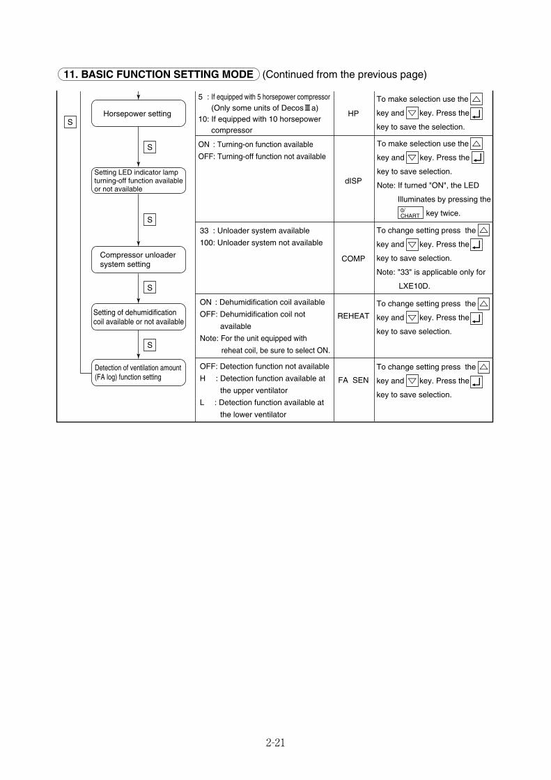
2-21
11. BASIC FUNCTION SETTING MODE (Continued from the previous page)
To make selection use the
key and key. Press the
key to save the selection.
To make selection use the
key and key. Press the
key to save selection.
Note: If turned "ON", the LED
Illuminates by pressing the
key twice.
To change setting press the
key and key. Press the
key to save selection.
To change setting press the
key and key. Press the
key to save selection.
5 : If equipped with 5 horsepower compressor (Only some units of DecosⅢa)
10: If equipped with 10 horsepower compressor
ON : Turning-on function available
OFF: Turning-off function not available
33 : Unloader system available
100: Unloader system not available
ON : Dehumidification coil available
OFF: Dehumidification coil not
available
Note: For the unit equipped with
reheat coil, be sure to select ON.
HP
dISP
COMP
REHEAT
OFF: Detection function not available
H : Detection function available at
the upper ventilator
L : Detection function available at
the lower ventilator
FA SEN
0/CHART
To change setting press the
key and key. Press the
key to save selection.
Note: "33" is applicable only for
LXE10D.
S
S
S
S
S
Detection of ventilation amount (FA log) function setting
Setting LED indicator lamp turning-off function available or not available
Horsepower setting
Setting of dehumidification coil available or not available
Compressor unloader system setting
02_16-27_LXE10E100以降_E.qxd 15.3.4 11:14 AM ページ 2-21
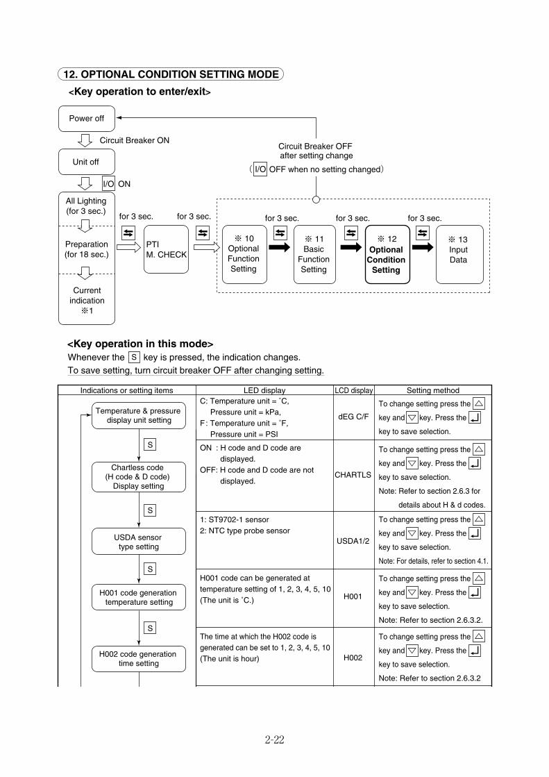
2-22
12. OPTIONAL CONDITION SETTING MODE
<Key operation to enter/exit>
<Key operation in this mode>Whenever the key is pressed, the indication changes.To save setting, turn circuit breaker OFF after changing setting.
S
LED display LCD display Setting methodIndications or setting itemsC: Temperature unit = ˚C, Pressure unit = kPa, F : Temperature unit = ˚F, Pressure unit = PSI
ON : H code and D code are displayed.
OFF: H code and D code are not displayed.
1: ST9702-1 sensor2: NTC type probe sensor
H001 code can be generated at temperature setting of 1, 2, 3, 4, 5, 10(The unit is ˚C.)
The time at which the H002 code is generated can be set to 1, 2, 3, 4, 5, 10(The unit is hour)
dEG C/F
CHARTLS
USDA1/2
H001
H002
To change setting press the
key and key. Press the
key to save selection.
To change setting press the
key and key. Press the
key to save selection.
Note: Refer to section 2.6.3 for
details about H & d codes.
To change setting press the
key and key. Press the
key to save selection.
Note: For details, refer to section 4.1.
To change setting press the
key and key. Press the
key to save selection.
Note: Refer to section 2.6.3.2.
To change setting press the
key and key. Press the
key to save selection.
Note: Refer to section 2.6.3.2
S
Temperature & pressure display unit setting
Chartless code (H code & D code)
Display setting
USDA sensor type setting
H001 code generation temperature setting
H002 code generation time setting
S
S
S
I/O ON
※ 10 ※ 11 ※ 13
Power off
Unit off
All Lighting(for 3 sec.)
Preparation(for 18 sec.)
Currentindication※1
Circuit Breaker ON
for 3 sec. for 3 sec. for 3 sec. for 3 sec. for 3 sec.
※ 12OptionalFunctionSetting
BasicFunctionSetting
OptionalCondition
Setting
InputData
I/O
Circuit Breaker OFF after setting change
( OFF when no setting changed)
PTIM. CHECK
02_16-27_LXE10E100以降_E.qxd 15.3.4 11:14 AM ページ 2-22
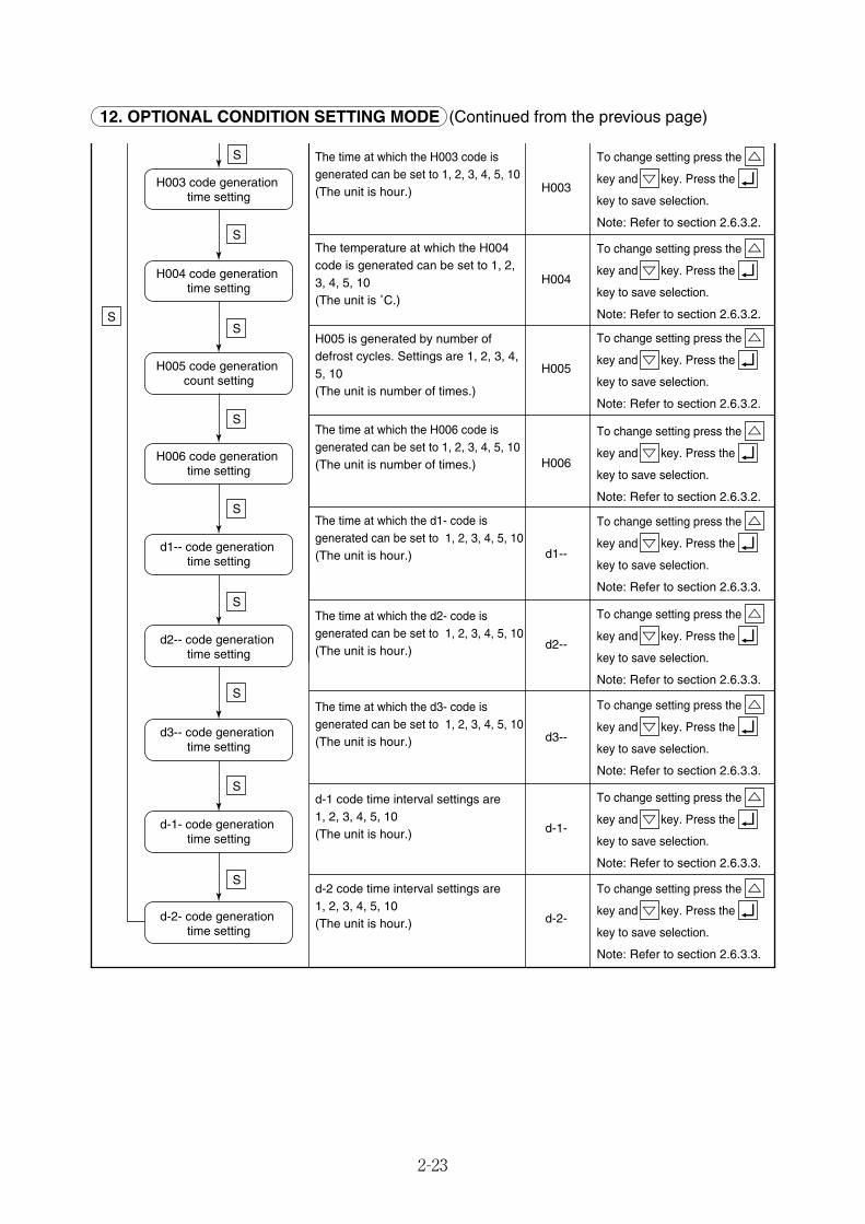
2-23
12. OPTIONAL CONDITION SETTING MODE (Continued from the previous page)
The time at which the H003 code is generated can be set to 1, 2, 3, 4, 5, 10(The unit is hour.)
The temperature at which the H004 code is generated can be set to 1, 2, 3, 4, 5, 10(The unit is ˚C.)
H005 is generated by number of defrost cycles. Settings are 1, 2, 3, 4, 5, 10(The unit is number of times.)
The time at which the H006 code is generated can be set to 1, 2, 3, 4, 5, 10(The unit is number of times.)
The time at which the d1- code is generated can be set to 1, 2, 3, 4, 5, 10(The unit is hour.)
The time at which the d2- code is generated can be set to 1, 2, 3, 4, 5, 10(The unit is hour.)
The time at which the d3- code is generated can be set to 1, 2, 3, 4, 5, 10(The unit is hour.)
d-1 code time interval settings are 1, 2, 3, 4, 5, 10(The unit is hour.)
d-2 code time interval settings are 1, 2, 3, 4, 5, 10(The unit is hour.)
H003
H004
H005
H006
d1--
d2--
d3--
d-1-
d-2-
To change setting press the
key and key. Press the
key to save selection.
Note: Refer to section 2.6.3.2.
To change setting press the
key and key. Press the
key to save selection.
Note: Refer to section 2.6.3.2.
To change setting press the
key and key. Press the
key to save selection.
Note: Refer to section 2.6.3.2.
To change setting press the
key and key. Press the
key to save selection.
Note: Refer to section 2.6.3.2.
To change setting press the
key and key. Press the
key to save selection.
Note: Refer to section 2.6.3.3.
To change setting press the
key and key. Press the
key to save selection.
Note: Refer to section 2.6.3.3.
To change setting press the
key and key. Press the
key to save selection.
Note: Refer to section 2.6.3.3.
To change setting press the
key and key. Press the
key to save selection.
Note: Refer to section 2.6.3.3.
To change setting press the
key and key. Press the
key to save selection.
Note: Refer to section 2.6.3.3.
S
H003 code generation time setting
H004 code generation time setting
H005 code generation count setting
H006 code generation time setting
d1-- code generation time setting
d2-- code generation time setting
d3-- code generation time setting
d-1- code generation time setting
d-2- code generation time setting
S
S
S
S
S
S
S
S
S
02_16-27_LXE10E100以降_E.qxd 15.3.4 11:14 AM ページ 2-23
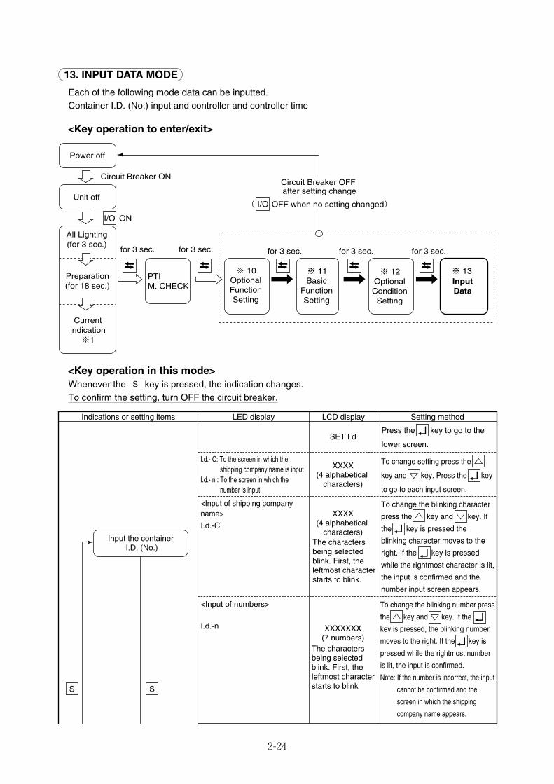
2-24
13. INPUT DATA MODE
Each of the following mode data can be inputted.Container I.D. (No.) input and controller and controller time
<Key operation to enter/exit>
I/O ON
※ 10 ※ 11
Power off
Unit off
All Lighting(for 3 sec.)
Preparation(for 18 sec.)
Currentindication※1
Circuit Breaker ON
for 3 sec. for 3 sec. for 3 sec. for 3 sec. for 3 sec.
※ 12 ※ 13OptionalFunctionSetting
BasicFunctionSetting
OptionalConditionSetting
InputData
I/O
Circuit Breaker OFF after setting change
( OFF when no setting changed)
PTIM. CHECK
LED display LCD display Setting methodIndications or setting items
I.d.- C: To the screen in which the shipping company name is input
I.d.- n : To the screen in which the number is input
<Input of shipping company name>
I.d.-C
<Input of numbers>
I.d.-n
SET I.d
To change setting press the
key and key. Press the key
to go to each input screen.
Press the key to go to the
lower screen.
XXXX(4 alphabetical
characters)
XXXX(4 alphabetical
characters)The characters being selected blink. First, the leftmost character starts to blink.
XXXXXXX(7 numbers)
The characters being selected blink. First, the leftmost character starts to blink
To change the blinking character
press the key and key. If
the key is pressed the
blinking character moves to the
right. If the key is pressed
while the rightmost character is lit,
the input is confirmed and the
number input screen appears.
To change the blinking number press
the key and key. If the
key is pressed, the blinking number
moves to the right. If the key is
pressed while the rightmost number
is lit, the input is confirmed.
Note: If the number is incorrect, the input
cannot be confirmed and the
screen in which the shipping
company name appears.
SS
Input the container I.D. (No.)
<Key operation in this mode>Whenever the key is pressed, the indication changes.To confirm the setting, turn OFF the circuit breaker.
S
02_16-27_LXE10E100以降_E.qxd 15.3.4 11:14 AM ページ 2-24

2-25
14. CONTROLLER SOFTWARE DOWNLOAD MODE
The data on a personal computer and a controller are interchanged in this mode.For details, see the Operation Manual for Personal computer software.Downloading is possible even in "3. BATTTERY MODE". page 2-9.
<Key operation to enter/exit>
──
20XX
(The A.D. year currently set)
XX
(The month currently set)
XX
(The day currently set)
XX
(The hour currently set)
XX
(The minute currently set)
SET TIME
YEAR
MONTH
dAY
HOUR
MINUTE
Press the key to go to the
next "Year" setting screen.
The value can be increased or decreased by pressing the key and key. Press the key to save selection and go to the next "Month" setting screen.
The value can be increased or decreased by pressing the key and key. Press the key to save selection and go to the next "Day" setting screen.
Make the setting in the same manner as described above. Save selection to go to the next "Hour" setting screen.
Make the setting in the same manner as described above. Save selection to go to the next "Minute" setting screen.
Make the setting in the same
manner as described above.
Controller time input
I/O ON
Power off
Unit off
All Lighting(for 3 sec.)
Preparation(for 18 sec.)
Currentindication※1
Circuit Breaker ON
※14 Downloading from controller
13. INPUT DATA MODE (Continued from the previous page)
02_16-27_LXE10E100以降_E.qxd 15.3.4 11:14 AM ページ 2-25
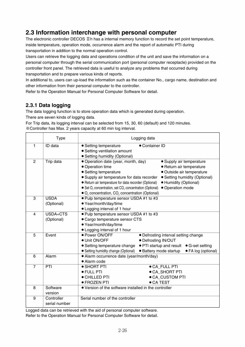
2-26
2.3 Information interchange with personal computerThe electronic controller DECOS 3h has a internal memory function to record the set point temperature,inside temperature, operation mode, occurrence alarm and the report of automatic PTI duringtransportation in addition to the normal operation control.Users can retrieve the logging data and operations condition of the unit and save the information on apersonal computer through the serial communication port (personal computer receptacle) provided on thecontroller front panel. The retrieved data is useful to analyze any problems that occurred duringtransportation and to prepare various kinds of reports.In additional to, users can up-load the information such as the container No., cargo name, destination andother information from their personal computer to the controller.Refer to the Operation Manual for Personal Computer Software for detail.
Logged data can be retrieved with the aid of personal computer software.Refer to the Operation Manual for Personal Computer Software for detail.
2.3.1 Data loggingThe data logging function is to store operation data which is generated during operation.There are seven kinds of logging data.For Trip data, its logging interval can be selected from 15, 30, 60 (default) and 120 minutes.※Controller has Max. 2 years capacity at 60 min log interval.
Type Logging data
1 ID data ¡Setting temperature ¡Container ID¡Setting ventilation amount¡Setting humidity (Optional)
2 Trip data ¡Operation date (year, month, day) ¡Supply air temperature¡Operation time ¡Return air temperature¡Setting temperature ¡Outside air temperature¡Supply air temperature for data recorder ¡Setting humidity (Optional)¡Return air temperature for data recorder (Optional) ¡Humidity (Optional)¡Set O2 concentration, set CO2 concentration (Optional) ¡Operation mode¡O2 concentration, CO2 concentration (Optional)
3 USDA ¡Pulp temperature sensor USDA #1 to #3(Optional) ¡Year/month/day/time
¡Logging interval of 1 hour4 USDA+CTS ¡Pulp temperature sensor USDA #1 to #3
(Optional) ¡Cargo temperature sensor CTS¡Year/month/day/time¡Logging interval of 1 hour
5 Event ¡Power ON/OFF ¡Defrosting interval setting change¡Unit ON/OFF ¡Defrosting IN/OUT¡Setting temperature change ¡PTI startup and result ¡G-set setting¡Setting humidity change (Optional) ¡Battery mode startup ¡FA log (optional)
6 Alarm ¡Alarm occurrence date (year/month/day)¡Alarm code
7 PTI ¡SHORT PTI ¡CA_FULL PTI¡FULL PTI ¡CA_SHORT PTI¡CHILLED PTI ¡CA_CUSTOM PTI¡FROZEN PTI ¡CA TEST
8 Software ¡Version of the software installed in the controllerversion
9 Controller Serial number of the controllerserial number
02_16-27_LXE10E100以降_E.qxd 15.3.4 11:14 AM ページ 2-26
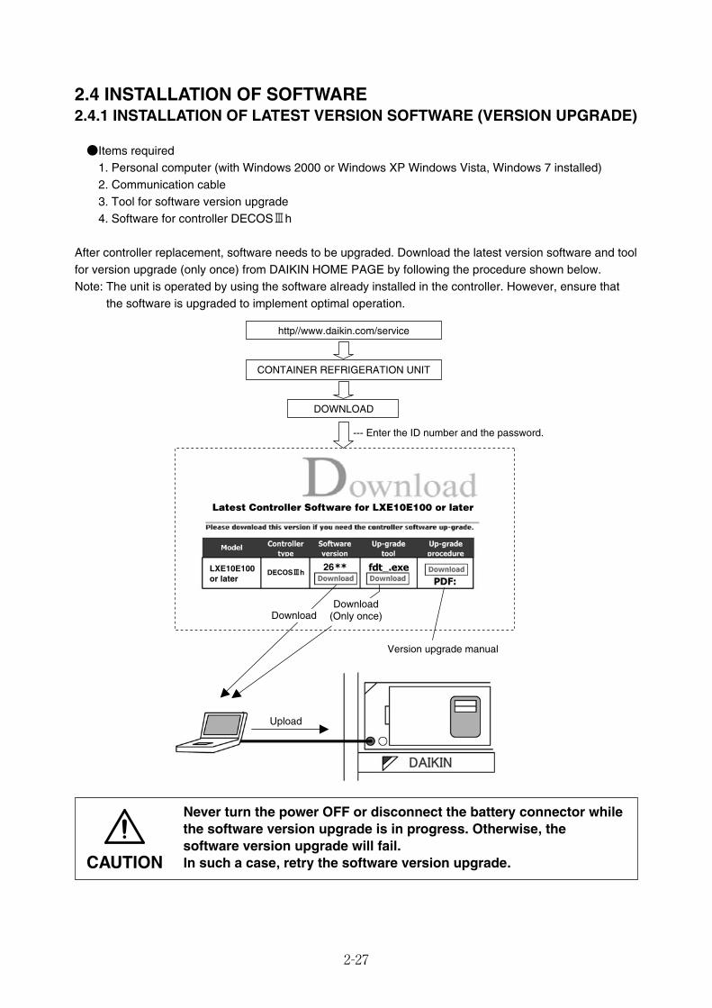
2-27
2.4 INSTALLATION OF SOFTWARE2.4.1 INSTALLATION OF LATEST VERSION SOFTWARE (VERSION UPGRADE)
●Items required1. Personal computer (with Windows 2000 or Windows XP Windows Vista, Windows 7 installed)2. Communication cable3. Tool for software version upgrade 4. Software for controller DECOSⅢh
After controller replacement, software needs to be upgraded. Download the latest version software and toolfor version upgrade (only once) from DAIKIN HOME PAGE by following the procedure shown below.Note: The unit is operated by using the software already installed in the controller. However, ensure that
the software is upgraded to implement optimal operation.
CONTAINER REFRIGERATION UNIT
DOWNLOAD
--- Enter the ID number and the password.
Version upgrade manual
Upload
http//www.daikin.com/service
Download(Only once)Download
LXE10E100 or later
Latest Controller Software for LXE10E100 or later
26DECOSⅢh
Never turn the power OFF or disconnect the battery connector whilethe software version upgrade is in progress. Otherwise, thesoftware version upgrade will fail.In such a case, retry the software version upgrade.CAUTION
02_16-27_LXE10E100以降_E.qxd 15.3.4 11:14 AM ページ 2-27
2-28
2.5 Pre-trip inspection● Perform a pre-trip inspection of each component and take remedial actions if necessary so that the
unit will operate normally. Pre trip inspection includes items listed below.Precautions regarding long-term storage (three months or longer)
When the refrigeration unit is stored for a long time, give consideration to temperature and humidity.Additionally, it is recommended to manually turn the rotating shaft of the evaporator and the condenserfan motor periodically to prevent poor lubrication of rotating shaft parts.Wash the inside of the box prior to storing the marine type container refrigerator. If the inside of the boxis not sufficiently dried out, the temperature and relative humidity within the box will both increase insituations such as when the external temperature increases, which will lead to a harsh ambientenvironment for the fan motor.Ensure that no water remains within the box during storage.
Note) If you have set the CA unit's on board ON/OFF setting to "ON," refer to the CA service manual for theMarine type Container Refrigeration Unit.
(1) Appearance inspection of unitq Physical damagew Wiring and refrigerant lines routed through flame casing insulatione Drain hose (dust and clogging)r Power cable and plug damaget Condition of refrigerant piping fasteners.y Condition of each sensor installationu Loose mounting hardware
� Bolts and nuts ----- Casing frame, compressor, fan motor and control box� Cable glands ----- Control box
i Conditions of control box cover seals (water-proof)o Magnetic contactor contact point.
02_28-36_LXE10E100以降_E.qxd 15.3.3 3:51 PM ページ 2-28
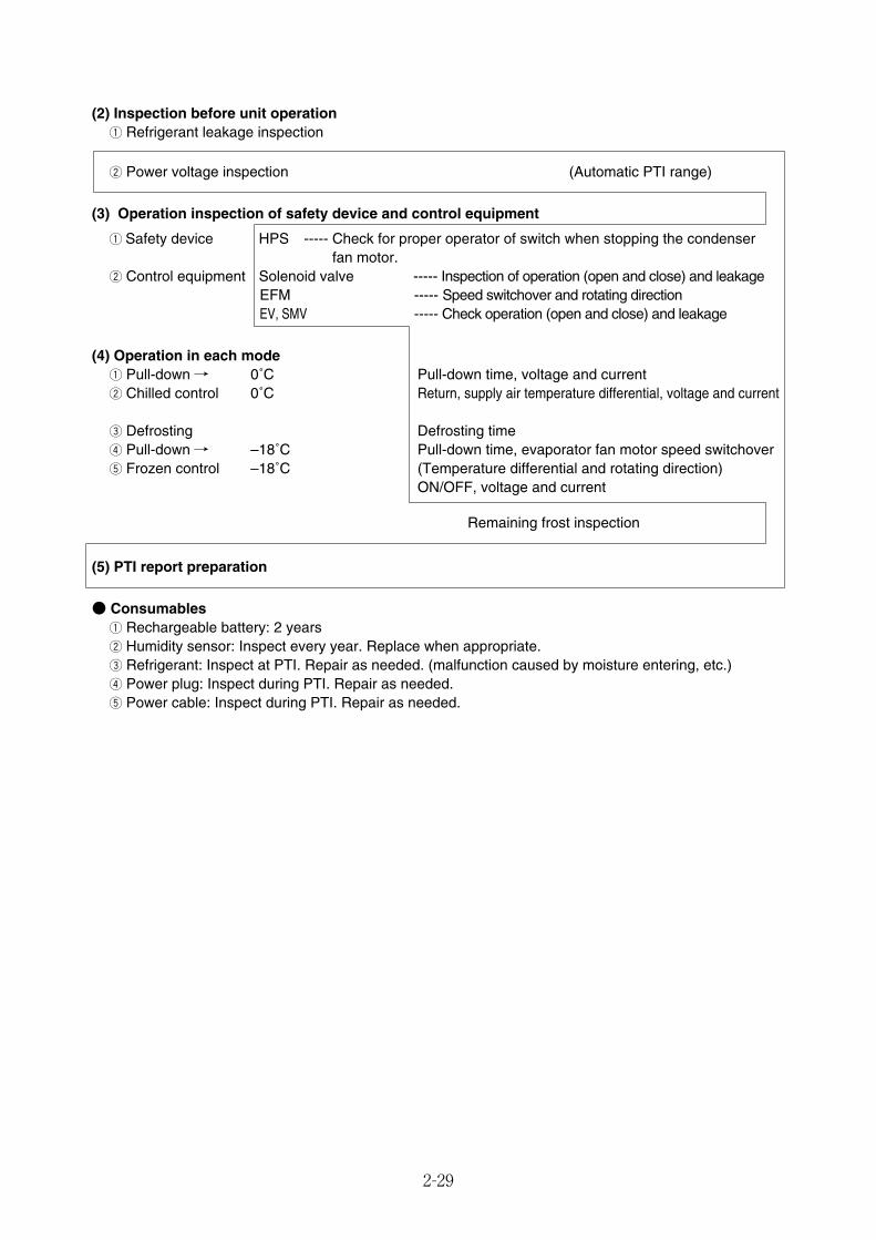
2-29
(2) Inspection before unit operationq Refrigerant leakage inspection
w Power voltage inspection (Automatic PTI range)
(3) Operation inspection of safety device and control equipment
q Safety device HPS ----- Check for proper operator of switch when stopping the condenser fan motor.
w Control equipment Solenoid valve ----- Inspection of operation (open and close) and leakageEFM ----- Speed switchover and rotating directionEV, SMV ----- Check operation (open and close) and leakage
(4) Operation in each modeq Pull-down / 0˚C Pull-down time, voltage and currentw Chilled control 0˚C Return, supply air temperature differential, voltage and current
e Defrosting Defrosting timer Pull-down / –18˚C Pull-down time, evaporator fan motor speed switchovert Frozen control –18˚C (Temperature differential and rotating direction)
ON/OFF, voltage and current
Remaining frost inspection
(5) PTI report preparation
● Consumablesq Rechargeable battery: 2 yearsw Humidity sensor: Inspect every year. Replace when appropriate.e Refrigerant: Inspect at PTI. Repair as needed. (malfunction caused by moisture entering, etc.)r Power plug: Inspect during PTI. Repair as needed.t Power cable: Inspect during PTI. Repair as needed.
02_28-36_LXE10E100以降_E.qxd 15.3.3 3:51 PM ページ 2-29
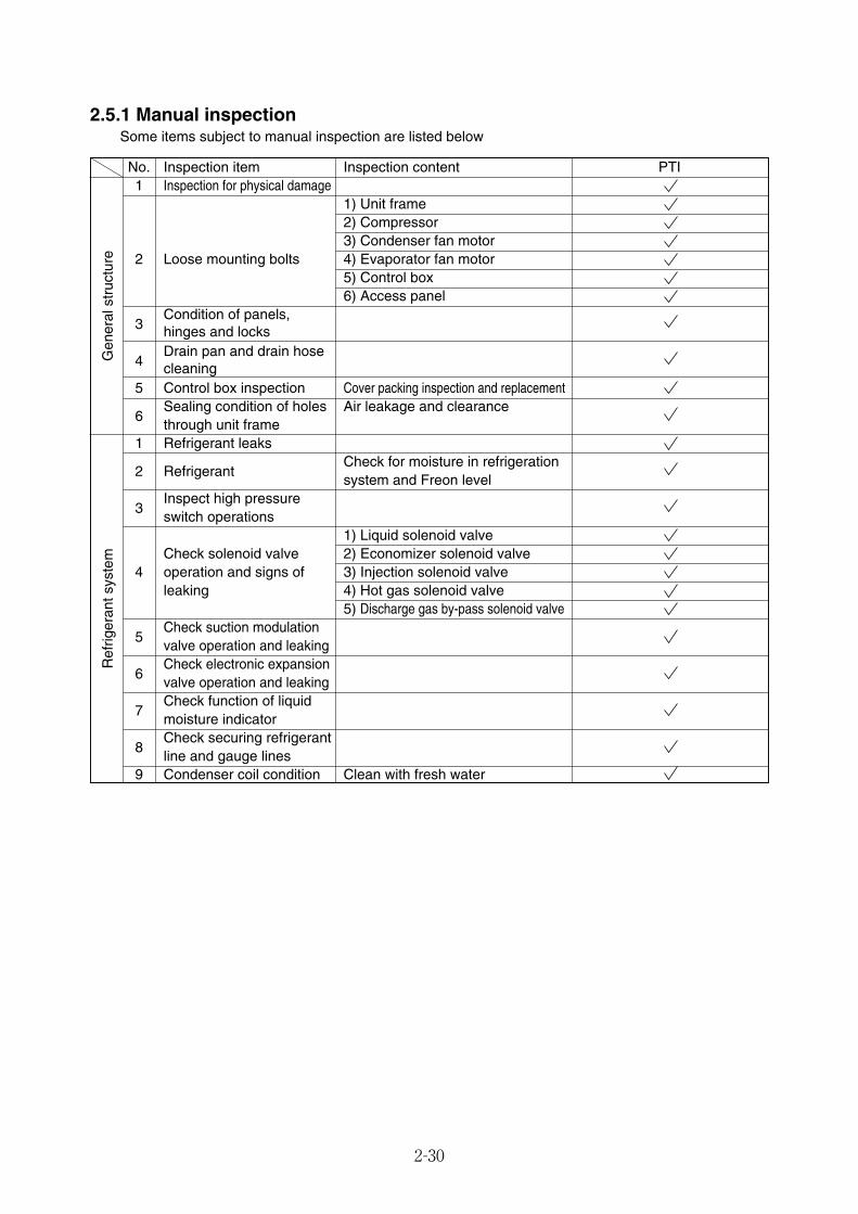
No. Inspection item Inspection content PTI1 Inspection for physical damage
1) Unit frame2) Compressor3) Condenser fan motor
2 Loose mounting bolts 4) Evaporator fan motor5) Control box6) Access panel
3Condition of panels, hinges and locks
4Drain pan and drain hosecleaning
5 Control box inspection Cover packing inspection and replacement
6Sealing condition of holes Air leakage and clearancethrough unit frame
1 Refrigerant leaks
2 RefrigerantCheck for moisture in refrigeration system and Freon level
3Inspect high pressureswitch operations
1) Liquid solenoid valveCheck solenoid valve 2) Economizer solenoid valve
4 operation and signs of 3) Injection solenoid valveleaking 4) Hot gas solenoid valve
5) Discharge gas by-pass solenoid valve
5Check suction modulation valve operation and leaking
6Check electronic expansion valve operation and leaking
7Check function of liquid moisture indicator
8Check securing refrigerant line and gauge lines
9 Condenser coil condition Clean with fresh water
2-30
2.5.1 Manual inspectionSome items subject to manual inspection are listed below
Ref
riger
ants
yste
mG
ener
alst
ruct
ure
02_28-36_LXE10E100以降_E.qxd 15.3.3 3:51 PM ページ 2-30
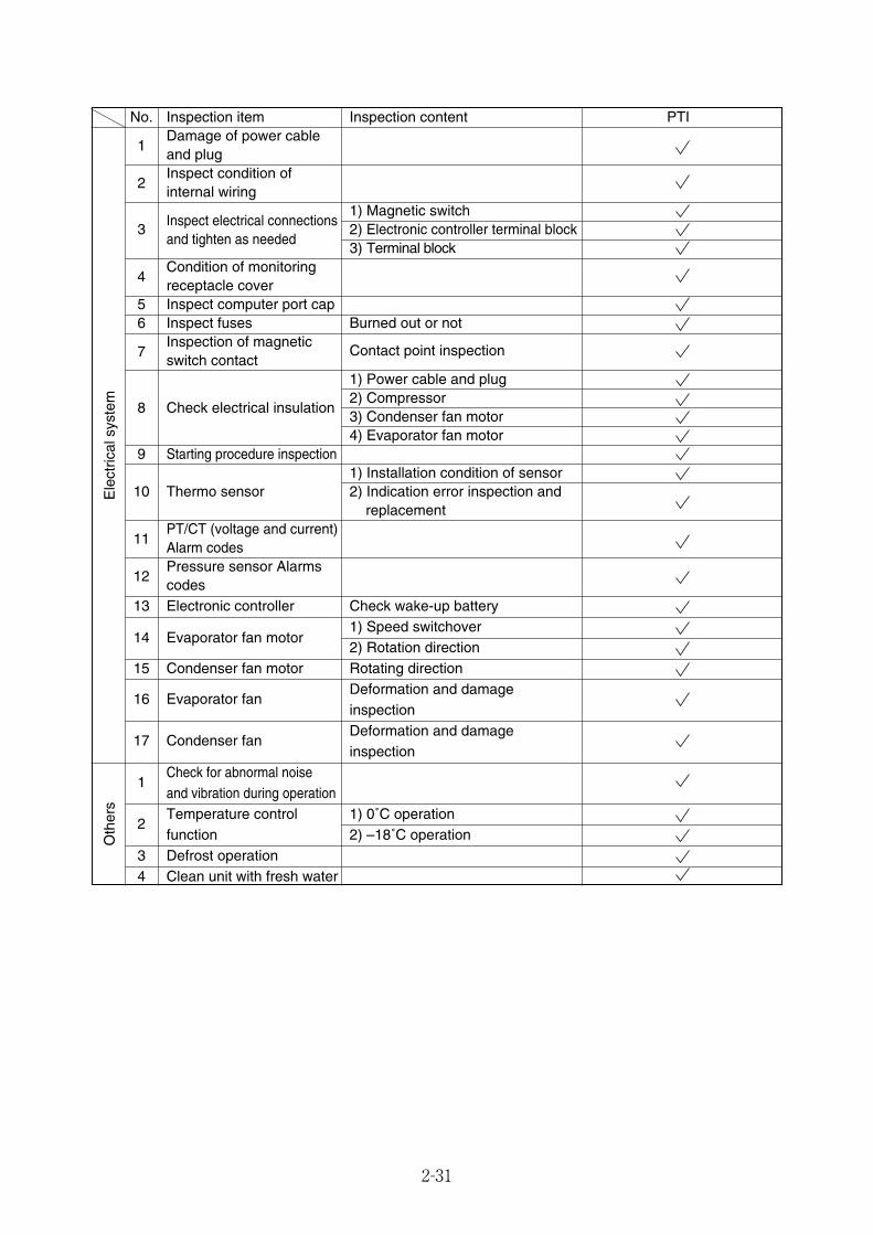
No. Inspection item Inspection content PTI
1Damage of power cableand plug
2Inspect condition of internal wiring
Inspect electrical connections1) Magnetic switch
3and tighten as needed
2) Electronic controller terminal block3) Terminal block
4Condition of monitoring receptacle cover
5 Inspect computer port cap6 Inspect fuses Burned out or not
7Inspection of magneticswitch contact
Contact point inspection
1) Power cable and plug
8 Check electrical insulation2) Compressor3) Condenser fan motor4) Evaporator fan motor
9 Starting procedure inspection1) Installation condition of sensor
10 Thermo sensor 2) Indication error inspection and replacement
11PT/CT (voltage and current) Alarm codes
12Pressure sensor Alarms codes
13 Electronic controller Check wake-up battery1) Speed switchover
14 Evaporator fan motor2) Rotation direction
15 Condenser fan motor Rotating direction
16 Evaporator fanDeformation and damage inspection
17 Condenser fanDeformation and damageinspection
1Check for abnormal noiseand vibration during operation
2Temperature control 1) 0˚C operationfunction 2) –18˚C operation
3 Defrost operation4 Clean unit with fresh water
2-31
Ele
ctric
alsy
stem
Oth
ers
02_28-36_LXE10E100以降_E.qxd 15.3.3 3:51 PM ページ 2-31

2-32
To start Full PTI, press while LCD screen displays "FULL PTI".
To start Short PTI, press while LCD screen displays "SHORT PTI".
To start Chilled PTI, press while LCD screendisplays "C-CHILL".
To start Frozen PTI, press while LCD screendisplays "C-FROZN"
To start manual check, press while LCD screen displays"M.CHECK" For details, refer to 2.5.2.4
2.5.2 Automatic PTI●In order to initiate an automatic PTI the following conditions must be present
43˚C≧ambient temperature≧–10.0˚CAn accurate result of the PTI may not be provided if the ambient temperature is above 43˚C orbelow –10˚C, or if it has big difference between Cargo and ambient temperature.(As a guideline, thedifference of temperature is more than 20˚C). Alarm J501 will be indicated except for Short PTI
●Automatic PTI includes Short PTI, Full PTI, Custom PTI (Chilled PTI, and Frozen PTI)
I/O ON
for 3 sec.
Power off
Unit off
All indication Lights on
(for 3 sec.)
Starting Preparation(for 18 sec.)
Circuit Breaker ON
for 3 sec.
F. PTIS. PTIC. PTIM. CHECK
PTI Content
Full PTI Short PTI, Chilled PTI and Frozen PTI are performed.
It terminates as soon as abnormalities are found after the completion of Short PTI
Frozen
PTI
Short PTI and Frozen PTI are performed.
It terminates as soon as abnormalities are found after the completion of Short PTI
Short PTI Performed in order to find parts abnormalities. PTI continues even if abnormalities are found
during PTI. PTI terminates if controller detects a compressor failure or evaporator fan is locked.
Chilled
PTI
Short PTI and Chilled PTI are performed.
It terminates as soon as abnormalities are found after the completion of Short PTI
2.5.2.1 Automatic PTI selection mode
Custom
PTI
02_28-36_LXE10E100以降_E.qxd 15.3.3 3:51 PM ページ 2-32
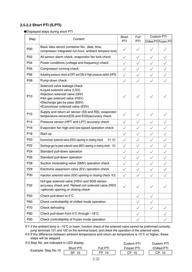
2-33
2.5.2.2 Short PTI (S.PTI)
●Displayed steps during short PTI
※1 If the ambient temp is –10˚C or lower, function check of the solenoid valve cannot be preformed correctly,jump terminals 121 and 102 on the terminal board, and check the operation of the solenoid valve.
※2 If the difference between ambient temperature and return air temperature is 15˚C or higher, thesesteps will be skipped.
※3 Step No. are indicated in LED display.
StepFrozen PTI
P02
P90
P00
P80
ContentShortPTI
Full PTI Chilled PTI
Basic data record (container No., date, time,compressor integrated run-hour, ambient tempera ture)
All sensor alarm check, evaporator fan lock check
P04 Power conditions (voltage and frequency) check
P05 Compressor running check
P06 Actuating pressure check at OFF and ON of High pressure switch (HPS)
P08 Pump-down check
P10
Solenoid valve leakage check•Liquid solenoid valve (LSV)•Injection solenoid valve (ISV)•Hot gas solenoid valve (HSV)•Discharge gas by-pass (BSV)•Economizer solenoid valve (ESV)
P12Supply and return air sensor (SS and RS), evaporatortemperature sensor(EIS and EOS)accuracy check
P14 Pressure sensor (HPT and LPT) accuracy check
P16 Evaporator fan high and low-speed operation check
P18 Start up
P20 Economizer solenoid valve (ESV) opening or closing check ※1 ※2
P22 Discharge gas by-pass solenoid valve (BSV) opening or closing check ※2
P24 Standard pull-down operation
P26 Standard pull-down operation
P28 Suction modulating valve (SMV) operation check
P29 Electronic expansion valve (EV) operation check
P30 Injection solenoid valve (ISV) opening or closing check ※2
P32Hot-gas solenoid valve (HSV) and SGS sensoraccuracy check and Reheat coil solenoid valve (RSV-optional) opening or closing check
P50 Check pull-down to 0˚C
P60 Check controllability of chilled mode operation.
P70 Check defrosting
Check pull-down from 0˚C through –18˚C
Check controllability of frozen mode operation
Chilled PTICP 10
Example: Step No.10 Short PTI Full PTI Frozen PTI
SP 10 FP 10 CP 10
Custom PTI
Custom PTI Custom PTI
02_28-36_LXE10E100以降_E.qxd 15.3.3 3:51 PM ページ 2-33
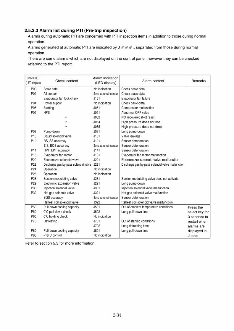
2-34
2.5.2.3 Alarm list during PTI (Pre-trip inspection)Alarms during automatic PTI are concerned with PTI inspection items in addition to those during normaloperation.Alarms generated at automatic PTI are indicated by J ※※※., separated from those during normaloperation.There are some alarms which are not displayed on the control panel, however they can be checkedreferring to the PTI report.
P00 Basic data No indication Check basic-dataP02 All sensor Same as normal operation Check basic-data
Evaporator fan lock check J161 Evaporator fan failureP04 Power supply No indication Check basic-dataP05 Starting J051 Compressor malfunctionP06 HPS J061 Abnormal OFF value
′′ J062 Not recovered (Not reset) ′′ J064 High pressure does not rise. ′′ J065 High pressure does not drop. P08 Pump-down J081 Long pump-down
P10 Liquid solenoid valve J101 Valve leakage P12 RS, SS accuracy J121 Sensor deterioration
EIS, EOS accuracy Same as normal operation Sensor deteriorationP14 HPT, LPT accuracy J141 Sensor deterioration
P16 Evaporator fan motor J161 Evaporator fan motor malfunction P20 Economizer solenoid valve J201 Economizer solenoid valve malfunction P22 Discharge gas by-pass solenoid valve J221 Discharge gas by-pass solenoid valve malfunction P24 Operation No indication P26 Operation No indication P28 Suction modulating valve J281 Suction modulating valve does not activate P29 Electronic expansion valve J291 Long pump-down P30 Injection solenoid valve J301 Injection solenoid valve malfunction P32 Hot-gas solenoid valve J321 Hot-gas solenoid valve malfunction SGS accuracy Same as normal operation Sensor deterioration
Reheat coil solenoid valve J322 Reheat coil solenoid valve malfunctionP50 Pull-down cooling capacity J501 Out of ambient temperature conditions
P50 0˚C pull-down check J502 Long pull-down time P60 0˚C holding check No indication P70 Defrosting J701 Out of starting conditions
J702 Long defrosting time P80 Pull-down cooling capacity J801 Long pull-down time P90 –18˚C control No indication
Check NO. (LED display)
Alarm Indication(LED display) Alarm content RemarksCheck content
Press the select key for 3 seconds to restart when alarms are displayed in J code
Refer to section 5.3 for more information.
02_28-36_LXE10E100以降_E.qxd 15.3.3 3:51 PM ページ 2-34
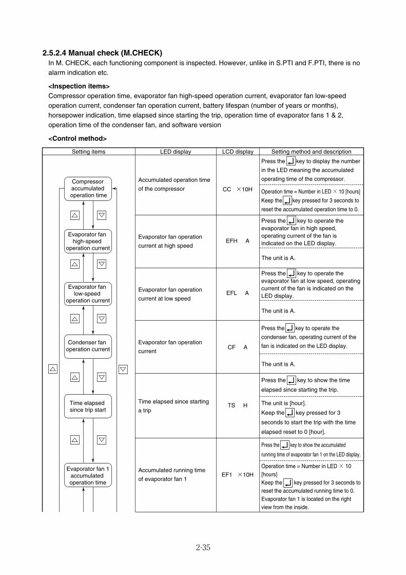
2-35
2.5.2.4 Manual check (M.CHECK)In M. CHECK, each functioning component is inspected. However, unlike in S.PTI and F.PTI, there is noalarm indication etc.
<Inspection items>Compressor operation time, evaporator fan high-speed operation current, evaporator fan low-speedoperation current, condenser fan operation current, battery lifespan (number of years or months),horsepower indication, time elapsed since starting the trip, operation time of evaporator fans 1 & 2,operation time of the condenser fan, and software version
<Control method>
LED display LCD display Setting method and descriptionSetting items
Accumulated operation time
of the compressor
Evaporator fan operation
current at high speed
Evaporator fan operation
current at low speed
Evaporator fan operation
current
Time elapsed since starting
a trip
Accumulated running time
of evaporator fan 1
CC ×10H
EFH A
The unit is A.
The unit is A.
The unit is A.
EFL A
CF A
TS H
EF1 ×10H
Press the key to display the number
in the LED meaning the accumulated
operating time of the compressor.
Press the key to operate the evaporator fan in high speed, operating current of the fan is indicated on the LED display.
Press the key to operate the evaporator fan at low speed, operating current of the fan is indicated on the LED display.
Press the key to operate the
condenser fan, operating current of the
fan is indicated on the LED display.
Press the key to show the time
elapsed since starting the trip.
Press the key to show the accumulated
running time of evaporator fan 1 on the LED display.
The unit is [hour].
Keep the key pressed for 3
seconds to start the trip with the time
elapsed reset to 0 [hour].
Operation time = Number in LED × 10 [hours]
Keep the key pressed for 3 seconds to
reset the accumulated operation time to 0.
Operation time = Number in LED × 10 [hours]Keep the key pressed for 3 seconds to reset the accumulated running time to 0.Evaporator fan 1 is located on the right view from the inside.
Compressor accumulated operation time
Evaporator fan high-speed
operation current
Evaporator fan low-speed
operation current
Condenser fan operation current
Time elapsed since trip start
Evaporator fan 1accumulated operation time
02_28-36_LXE10E100以降_E.qxd 15.3.3 3:51 PM ページ 2-35
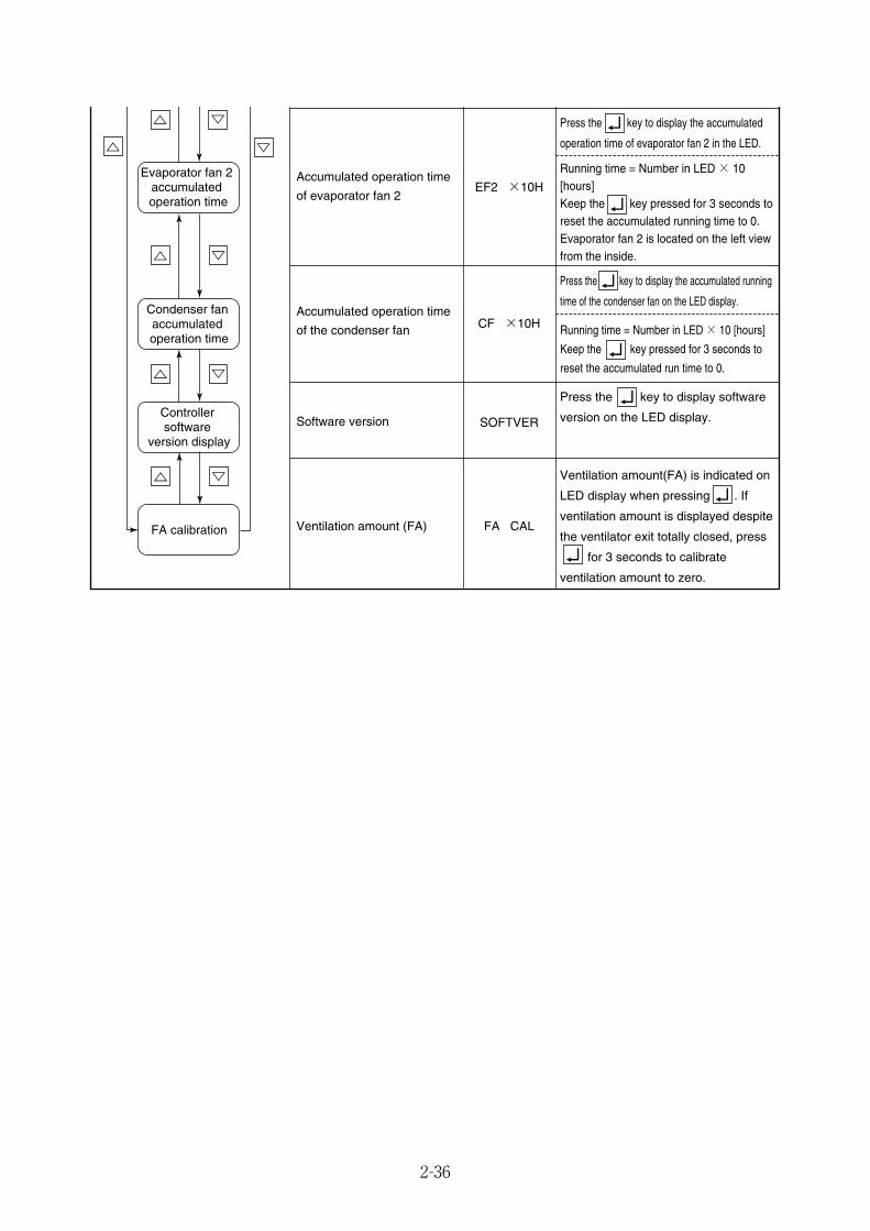
2-36
Accumulated operation time
of evaporator fan 2
Accumulated operation time
of the condenser fan
Software version
EF2 ×10H
CF ×10H
SOFTVER
Press the key to display the accumulated
operation time of evaporator fan 2 in the LED.
Press the key to display software
version on the LED display.
Ventilation amount (FA) FA CAL
Ventilation amount(FA) is indicated on
LED display when pressing . If
ventilation amount is displayed despite
the ventilator exit totally closed, press
for 3 seconds to calibrate
ventilation amount to zero.
Running time = Number in LED × 10 [hours]Keep the key pressed for 3 seconds to reset the accumulated running time to 0.Evaporator fan 2 is located on the left view from the inside.
Press the key to display the accumulated running
time of the condenser fan on the LED display.
Running time = Number in LED × 10 [hours]
Keep the key pressed for 3 seconds to
reset the accumulated run time to 0.
FA calibration
Evaporator fan 2 accumulated operation time
Condenser fan accumulated operation time
Controller software
version display
02_28-36_LXE10E100以降_E.qxd 15.3.3 3:51 PM ページ 2-36
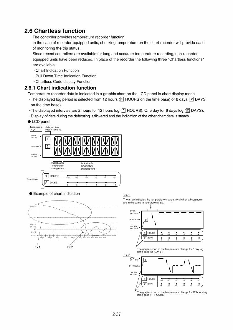
2.6 Chartless functionThe controller provides temperature recorder function.In the case of recorder-equipped units, checking temperature on the chart recorder will provide easeof monitoring the trip status.Since recent controllers are available for long and accurate temperature recording, non-recorder-equipped units have been reduced. In place of the recorder the following three "Chartless functions"are available.� Chart Indication Function� Pull Down Time Indication Function� Chartless Code display Function
2.6.1 Chart indication functionTemperature recorder data is indicated in a graphic chart on the LCD panel in chart display mode.� The displayed log period is selected from 12 hours ( HOURS on the time base) or 6 days ( DAYSon the time base).
� The displayed intervals are 2 hours for 12 hours log ( HOURS). One day for 6 days log ( DAYS).� Display of data during the defrosting is flickered and the indication of the other chart data is steady.● LCD panel
21
21
2-37
● Example of chart indication
Indication fortemperaturechanging state
Indication fortemperature
change trend
1
2
Temperaturerange
Selected timebase is lights up.
UNDER SP –5°C
IN RANGE
OVER SP+ 5°C
1 HOURS
2 DAYS–1–2–3–4–5–6
–2–4–6–8–10–12Time range
SP
SP– 5°C
SP+ 5°C
SP+ 2°C
SP– 2°C
–6days –5days –4days –3days –2days –1day –12hours –10hours –8hours –6hours –4hours –2hours
Ex.1 Ex.2
SP+10°C
SP+20°C
1
Ex.1
2
UNDER SP – 5°C
OVER SP + 5°C
IN RANGE
The graphic chart of the temperature change for 6 day log (time base : 2 (DAYS))
The graphic chart of the temperature change for 12 hours log (time base : 1 (HOURS))
The arrow indicates the temperature change trend when all segments are in the same temperature range.
Ex.2
1 HOURS
2 DAYS–1–2–3–4–5–6
–2–4–6–8–10–12
UNDER SP – 5°C
OVER SP + 5°C
IN RANGE
1 HOURS
2 DAYS–1–2–3–4–5–6
–2–4–6–8–10–12
02_37-44_LXE10E100以降_E.qxd 2015.03.06 14:54 ページ 2-37
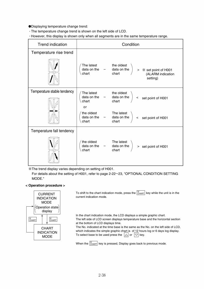
2-38
< Operation procedure >
CHARTINDICATION
MODE
CURRENTINDICATION
MODEOperation state
display
0/CHART
0/CHART
⎞⎟⎠
⎞⎟⎠
To shift to the chart indication mode, press the key while the unit is in thecurrent indication mode.
In the chart indication mode, the LCD displays a simple graphic chart.The left side of LCD screen displays temperature base and the horizontal sectionat the bottom of LCD displays time.The No. indicated at the time base is the same as the No. on the left side of LCD,which indicates the simple graphic chart is of 12 hours log or 6 days log display.To select base to be used press the or key.
When the key is pressed, Display goes back to previous mode.0/CHART
0/CHART
Temperature rise trend
Temperature stable tendency
Temperature fall tendency
Trend indication Condition
The latest data on the chart
the oldest data on the chart
※ set point of H001 (ALARM indication setting)
set point of H001
set point of H001
set point of H001
>–
The latest data on the chart
the oldest data on the chart
<–
the oldest data on the chart
The latest data on the chart
<–
the oldest data on the chart
The latest data on the chart
>–
or
●Displaying temperature change trend:� The temperature change trend is shown on the left side of LCD.� However, this display is shown only when all segments are in the same temperature range.
※The trend display varies depending on setting of H001.For details about the setting of H001, refer to page 2-22~23, "OPTIONAL CONDITION SETTINGMODE."
02_37-44_LXE10E100以降_E.qxd 2015.03.06 14:54 ページ 2-38
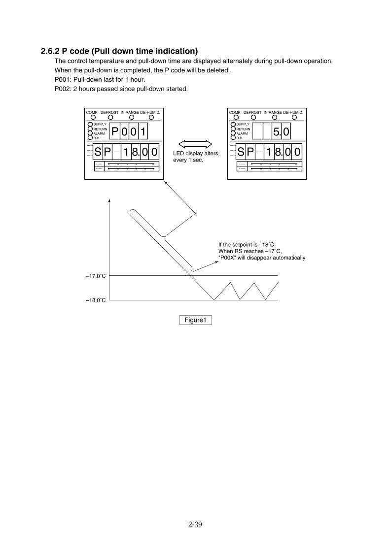
2-39
2.6.2 P code (Pull down time indication)The control temperature and pull-down time are displayed alternately during pull-down operation.When the pull-down is completed, the P code will be deleted.P001: Pull-down last for 1 hour. P002: 2 hours passed since pull-down started.
2 7 2.1 0 0---------------
----------
SUPPLY
RETURNALARMR.H.
COMP. DEFROST IN RANGE DE-HUMID.
00 1
S P
P
8.1 0 0 2 7 2.1 0 0---------------
----------
SUPPLY
RETURNALARMR.H.
COMP. DEFROST IN RANGE DE-HUMID.
5.0
S P 8.1 0 0
If the setpoint is –18˚C:When RS reaches –17˚C, "P00X" will disappear automatically
LED display alters every 1 sec.
–17.0˚C
–18.0˚C
Figure1
02_37-44_LXE10E100以降_E.qxd 2015.03.06 14:54 ページ 2-39

2-40
2.6.3 Chartless code display functionThe chartless code represents the coded inside air temperature.Select "ON" for the chartless code setting to display the code on the LED display.For the chartless code setting, refer to the "OPTIONAL CONDITION SETTING MODE" on pages 2-22~2-23.� P code: Indicates pull-down time.� H code: Indicates abnormal temperature records.� d code: Indicates operation history.
2.6.3.1 List of chartless codeC: chilled mode, F: Frozen mode
Note 1) The Circled value setting can be changed. Setting in the box varies
according to the Circled value setting.
Note 2) To delete the H code or d code, press the key for 3 seconds during the
relevant code indicated.
Note 3) H code and d code are deleted when the power supply is turned off for 3 days.
Code Description Operation mode Figure
Abn
orm
alte
mpe
ratu
rere
cord
H001Alarm is displayed when control temperature does not decrease by
3˚C or more, every 4 hours during pull-down operation.C, F 2
H002The alarm is displayed when the total out-of- in-range reaches 2 hours.
(Count is not performed during defrost.)C, F 3
H003The alarm is displayed when the integrated time of state "below SP-1˚C"
reaches 2 hours.C 4
H004The alarm is displayed when the integrated time of state "below SP-2˚C"
reaches 2 hours.C 4
H005
The alarm is displayed when control air temperature is Out-of Range and
defrosting was performed successively three times when the control air
temperature does not return to in-range.
C, F 5
H006The alarm is displayed when over 2 deg.C temperature difference between
control sensor and recording sensor more than 1 hour.C, F 6
Ope
ratio
nhi
stor
y
d3XXWhen temperature stays +3˚C above set point for 1 hour , XX = 01
will be displayed.C, F 7
d2XXWhen temperature stays +2˚C above set point for 1 hour , XX = 01
will be displayed.C 7
d1XXWhen temperature stays +1˚C above set point for 1 hour , XX = 01
will be displayed.C 7
d–1XWhen temperature stays -1˚C below set point for 1 hour , XX = 01
will be displayed.C 7
d–2XWhen temperature stays -2˚C below set point for 1 hour , 2X = 21
will be displayed.C 7
PXXXXXX: When the total pull-down time reaches one hour, will display
XXX=001 appears.C, F 1
02_37-44_LXE10E100以降_E.qxd 2015.03.06 14:54 ページ 2-40
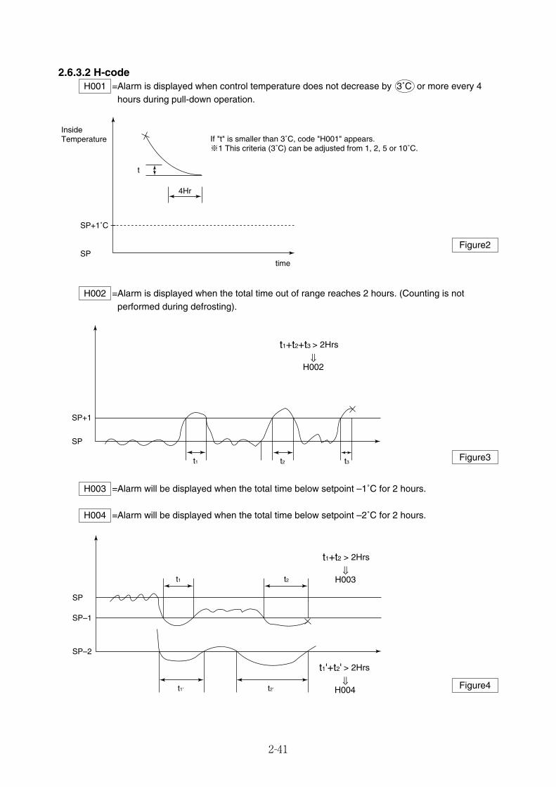
2-41
2.6.3.2 H-code=Alarm is displayed when control temperature does not decrease by 3˚C or more every 4
hours during pull-down operation.H001
=Alarm is displayed when the total time out of range reaches 2 hours. (Counting is notperformed during defrosting).
H002
=Alarm will be displayed when the total time below setpoint –1˚C for 2 hours.
=Alarm will be displayed when the total time below setpoint –2˚C for 2 hours.H004
H003
t
4Hr
SP+1˚C
SP
If "t" is smaller than 3˚C, code "H001" appears.※1 This criteria (3˚C) can be adjusted from 1, 2, 5 or 10˚C.
InsideTemperature
time
t1
> 2Hrs
H002
SP+1
SP
t2 t3
t1+t2+t3
> 2Hrs
H003
> 2Hrs
H004
SP–1
SP
SP–2
t1'
t1 t2
t2'
t1+t2
t1'+t2'
Figure2
Figure3
Figure4
02_37-44_LXE10E100以降_E.qxd 2015.03.06 14:54 ページ 2-41
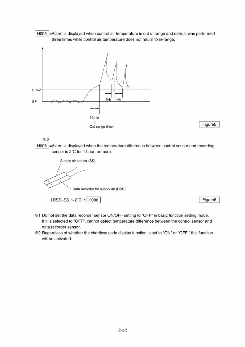
2-42
=Alarm is displayed when control air temperature is out of range and defrost was performedthree times while control air temperature does not return to in-range.
H005
30min
Out range timer
=
SP+2
SP4Hr 4Hr
Figure5
=Alarm is displayed when the temperature difference between control sensor and recordingsensor is 2˚C for 1 hour, or more.
H006
※1 Do not set the data recorder sensor ON/OFF setting to "OFF" in basic function setting mode.If it is selected to "OFF", cannot detect temperature difference between the control sensor anddata recorder sensor.
※2 Regardless of whether the chartless code display function is set to "ON" or "OFF," this functionwill be activated.
Supply air sensor (SS)
Data recorder for supply air (DSS)
DSS–SS > 2˚C→ H006 Figure6
※2
02_37-44_LXE10E100以降_E.qxd 2015.03.06 14:54 ページ 2-42
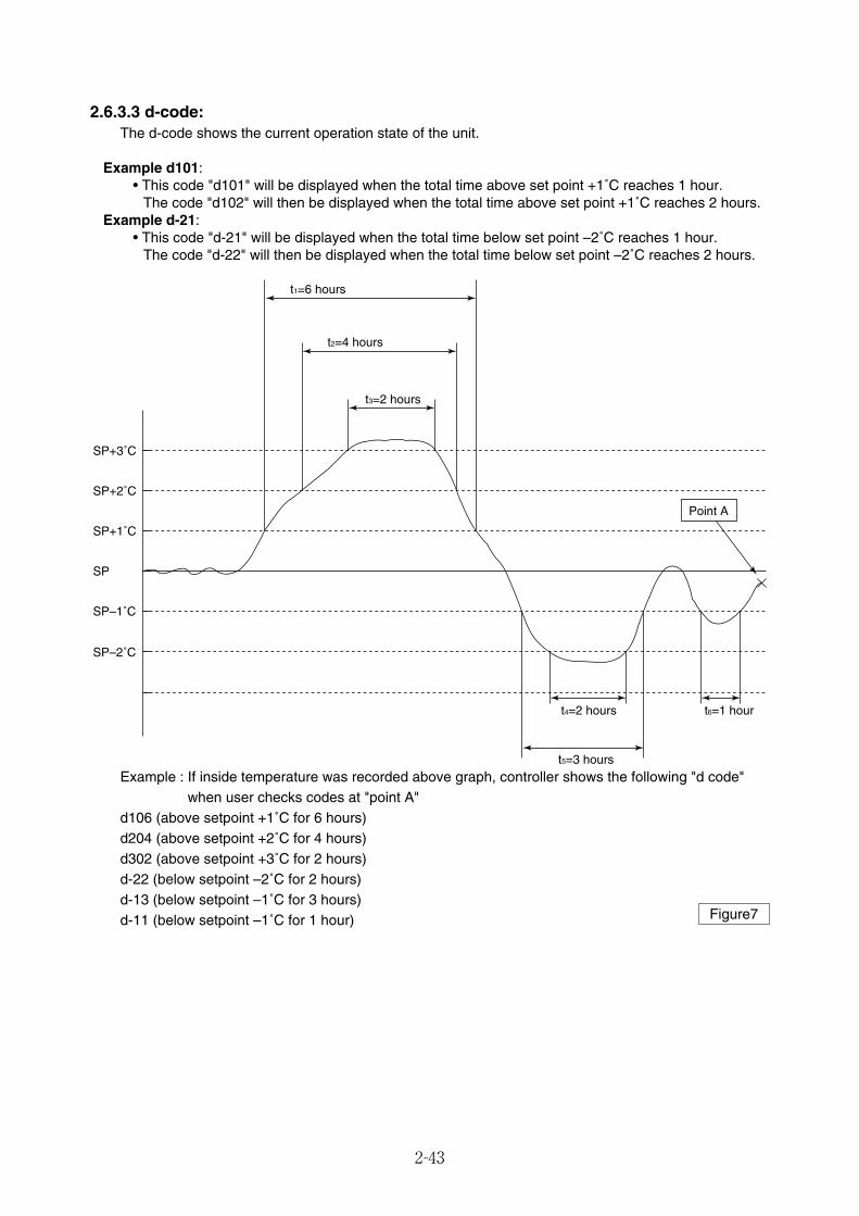
2-43
2.6.3.3 d-code:The d-code shows the current operation state of the unit.
Example d101:• This code "d101" will be displayed when the total time above set point +1˚C reaches 1 hour.
The code "d102" will then be displayed when the total time above set point +1˚C reaches 2 hours.Example d-21:
• This code "d-21" will be displayed when the total time below set point –2˚C reaches 1 hour.The code "d-22" will then be displayed when the total time below set point –2˚C reaches 2 hours.
SP–2˚C
SP–1˚C
SP
SP+1˚C
SP+2˚C
SP+3˚C
t1=6 hours
t2=4 hours
t3=2 hours
t4=2 hours t6=1 hour
t5=3 hours
Point A
Example : If inside temperature was recorded above graph, controller shows the following "d code"when user checks codes at "point A"
d106 (above setpoint +1˚C for 6 hours)d204 (above setpoint +2˚C for 4 hours)d302 (above setpoint +3˚C for 2 hours)d-22 (below setpoint –2˚C for 2 hours)d-13 (below setpoint –1˚C for 3 hours)d-11 (below setpoint –1˚C for 1 hour) Figure7
02_37-44_LXE10E100以降_E.qxd 2015.03.06 14:54 ページ 2-43
2-44
2.7 Communication modemDECOS 3 h controller can transmit operation data through power line, if slave modem is installed incontrol box.The slave modem shall be complied with ISO10368. The following items can be monitored and/or sendcommands via master modem: (*1)
Item Description¡Inside temperature and humidity ¡Sensor data¡Set point temperature ¡Trip data
Inquiries¡Defrosting interval ¡Alarm data
1 ¡Container No.(Remote monitoring)¡Logger header information¡Alarm¡Operation mode
Commands¡Set point temperature changing ¡Container No. changing
2 ¡Defrosting interval changing ¡Unit ON/OFF changing(Remote control)¡Manual defrosting initiation ¡Header information changing
(*1) According to the relationship among slave modem, Master modem and controller, items which canmonitor and/or 2-way communication are different. Please contact DAIKIN sales office if you have aspecific item to monitor or send commands.
02_37-44_LXE10E100以降_E.qxd 2015.03.06 14:54 ページ 2-44
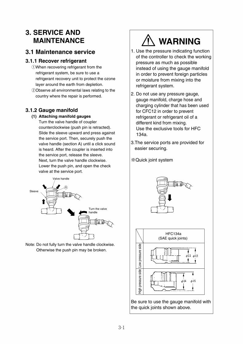
3-1
WARNING1. Use the pressure indicating function
of the controller to check the workingpressure as much as possibleinstead of using the gauge manifoldin order to prevent foreign particlesor moisture from mixing into therefrigerant system.
2. Do not use any pressure gauge,gauge manifold, charge hose andcharging cylinder that has been usedfor CFC12 in order to preventrefrigerant or refrigerant oil of adifferent kind from mixing.Use the exclusive tools for HFC134a.
3.The service ports are provided foreasier securing.
※Quick joint system
3. SERVICE ANDMAINTENANCE
3.1 Maintenance service3.1.1 Recover refrigerant
qWhen recovering refrigerant from therefrigerant system, be sure to use arefrigerant recovery unit to protect the ozonelayer around the earth from depletion.
wObserve all environmental laws relating to thecountry where the repair is performed.
3.1.2 Gauge manifold(1) Attaching manifold gauges
Turn the valve handle of couplercounterclockwise (push pin is retracted).Slide the sleeve upward and press againstthe service port. Then, securely push thevalve handle (section A) until a click soundis heard. After the coupler is inserted intothe service port, release the sleeve.Next, turn the valve handle clockwise.Lower the push pin, and open the checkvalve at the service port.
ASleeve
Valve handle
Turn the valve handle
Be sure to use the gauge manifold withthe quick joints shown above.
High
pre
ssur
e sid
eLo
w pr
essu
re s
ide
HFC134a(SAE quick joints)
Note: Do not fully turn the valve handle clockwise.Otherwise the push pin may be broken.
03_01-07_LXE10E100以降_E.qxd 15.3.4 11:15 AM ページ 3-1
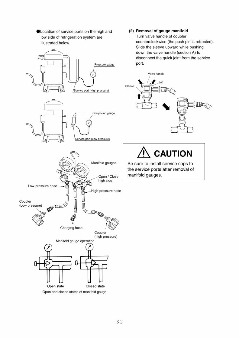
3-2
●Location of service ports on the high andlow side of refrigeration system areillustrated below.
Service port (Low pressure)
Compound gauge
Open state Closed state
Open and closed states of manifold gauge
Manifold gauges
Open / Close high side
High-pressure hoseLow-pressure hose
Coupler (Low pressure)
Charging hose
Manifold gauge operation
Coupler(high pressure)
Sleeve
Valve handle
A
Service port (High pressure)
Pressure gauge
(2) Removal of gauge manifoldTurn valve handle of couplercounterclockwise (the push pin is retracted).Slide the sleeve upward while pushingdown the valve handle (section A) todisconnect the quick joint from the serviceport.
CAUTIONBe sure to install service caps tothe service ports after removal ofmanifold gauges.
03_01-07_LXE10E100以降_E.qxd 15.3.4 11:15 AM ページ 3-2
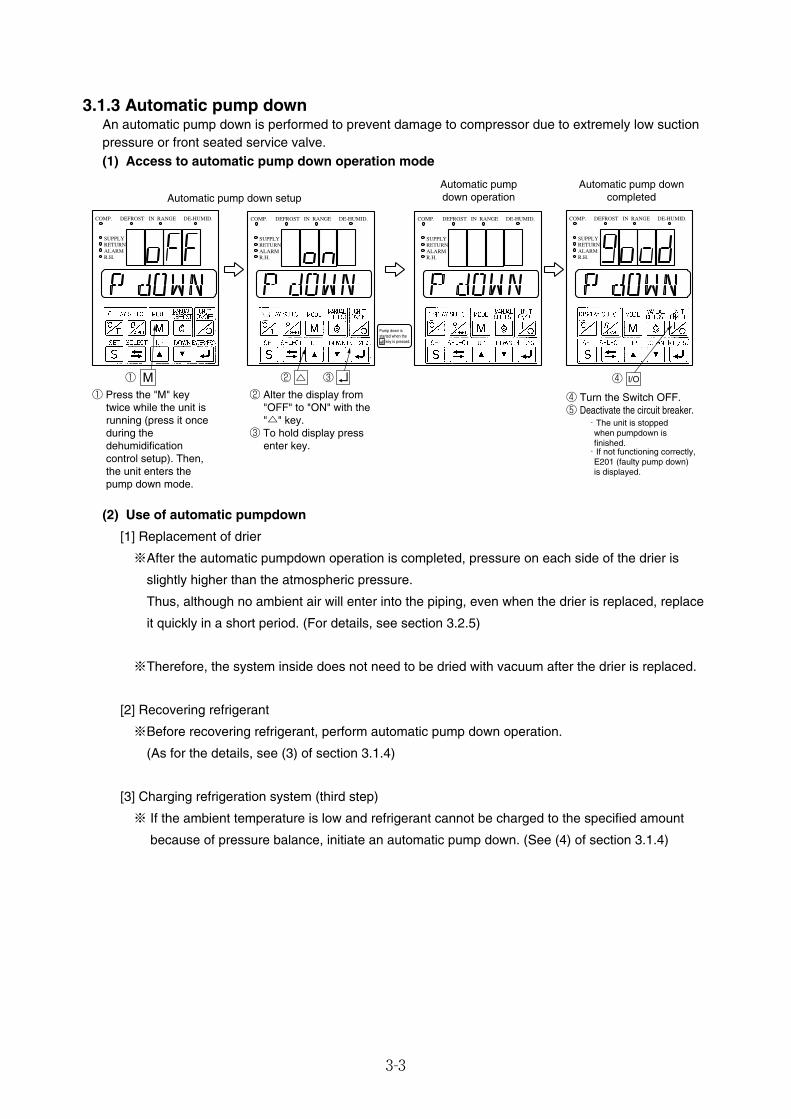
3-3
3.1.3 Automatic pump downAn automatic pump down is performed to prevent damage to compressor due to extremely low suctionpressure or front seated service valve.(1) Access to automatic pump down operation mode
M① ② ③ ④ I/O
COMP. DEFROST IN RANGE DE-HUMID.
SUPPLYRETURNALARMR.H.
COMP. DEFROST IN RANGE DE-HUMID.
SUPPLYRETURNALARMR.H.
COMP. DEFROST IN RANGE DE-HUMID.
SUPPLYRETURNALARMR.H.
COMP. DEFROST IN RANGE DE-HUMID.
SUPPLYRETURNALARMR.H.
Automatic pump down setupAutomatic pumpdown operation
Automatic pump downcompleted
④ Turn the Switch OFF.⑤ Deactivate the circuit breaker.
・If not functioning correctly, E201 (faulty pump down) is displayed.
・The unit is stopped when pumpdown is finished.
① Press the "M" key twice while the unit is running (press it once during the dehumidification control setup). Then, the unit enters the pump down mode.
② Alter the display from "OFF" to "ON" with the "△" key.
③ To hold display press enter key.
Pump down is started when the key is pressed.
(2) Use of automatic pumpdown
[1] Replacement of drier
※After the automatic pumpdown operation is completed, pressure on each side of the drier is
slightly higher than the atmospheric pressure.
Thus, although no ambient air will enter into the piping, even when the drier is replaced, replace
it quickly in a short period. (For details, see section 3.2.5)
※Therefore, the system inside does not need to be dried with vacuum after the drier is replaced.
[2] Recovering refrigerant
※Before recovering refrigerant, perform automatic pump down operation.
(As for the details, see (3) of section 3.1.4)
[3] Charging refrigeration system (third step)
※ If the ambient temperature is low and refrigerant cannot be charged to the specified amount
because of pressure balance, initiate an automatic pump down. (See (4) of section 3.1.4)
03_01-07_LXE10E100以降_E.qxd 15.3.4 11:15 AM ページ 3-3
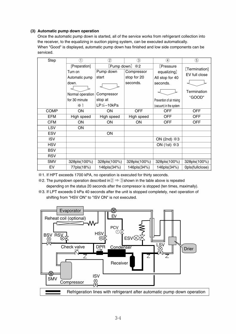
3-4
(3) Automatic pump down operationOnce the automatic pump down is started, all of the service works from refrigerant collection intothe receiver, to the equalizing in suction piping system, can be executed automatically.When "Good" is displayed, automatic pump down has finished and low side components can beserviced.
Step q w e r t
[Preparation]Turn onAutomatic pumpdown.
Normal operationfor 30 minute
※1
[Pump down]※2[Termination]
EV full close
Termination"GOOD"
Pump downstart
Compressorstop at LP≦–10kPa
Compressorstop for 20seconds.
COMP ON ON OFF OFF OFFEFM High speed High speed High speed OFF OFFCFM ON ON ON OFF OFFLSV ONESV ONISV ON (2nd) ※3HSV ON (1st) ※3
EV 77pls(18%) 146pls(34%) 146pls(34%) 146pls(34%) 0pls(fullclose)
[Pressureequalizing]
All stop for 40seconds.
Prevention of air mixing(vacuum) in the system
BSV
SMV 328pls(100%) 328pls(100%) 328pls(100%) 328pls(100%) 328pls(100%)RSV
Refrigeration lines with refrigerant after automatic pump down operation
HSV
Compressor
Reheat coil (optional)
BSV
LSV
ESV
EVEvaporator
RSV
DPR CondenserCheck valve
Receiver
SMVISV
Drier
PCVR
※1. If HPT exceeds 1700 kPA, no operation is executed for thirty seconds.※2. The pumpdown operation described inw⇒eshown in the table above is repeated
depending on the status 20 seconds after the compressor is stopped (ten times, maximally).※3. If LPT exceeds 0 kPa 40 seconds after the unit is stopped completely, next operation of
shifting from "HSV ON" to "ISV ON" is not executed.
03_01-07_LXE10E100以降_E.qxd 15.3.4 11:15 AM ページ 3-4
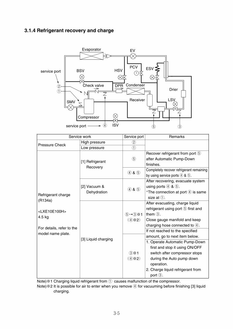
3-5
3.1.4 Refrigerant recovery and charge
Service work Service port Remarks
Pressure CheckHigh pressure w
q
Refrigerant charge(R134a)
<LXE10E100H>4.5 kg
For details, refer to themodel name plate.
[1] RefrigerantRecovery
t
Recover refrigerant from port tafter Automatic Pump-Downfinishes.
r & tCompletely recover refrigerant remainingby using service ports r & t.
[2] Vacuum &Dehydration
r & t
After recovering, evacuate systemusing ports r & t.※The connection at port r is samesize at q.
[3] Liquid charging
t→e※1(r※2)
After evacuating, charge liquidrefrigerant using port t first andthem e. Close gauge manifold and keepcharging hose connected to r.If not reached to the specifiedamount, go to next item below.1. Operate Automatic Pump-Down
first and stop it using ON/OFFswitch after compressor stopsduring the Auto pump downoperation.
2. Charge liquid refrigerant fromport e.
Low pressure
e※1(r※2)
LSV
etr
q
wDrier
ESV
EV
HSV
Receiver
CondenserCheck valve DPR
ISV
BSV
SMV
service port
service port
Compressor
Evaporator
PCVR
Note)※1 Charging liquid refrigerant from q causes malfunction of the compressor.Note)※2 It is possible for air to enter when you remove r for vacuuming before finishing [3] liquid
charging.
03_01-07_LXE10E100以降_E.qxd 15.3.4 11:15 AM ページ 3-5

3-6
(1) Check refrigeration pressuresCheck high pressure from the service port won the compressor discharge. Check lowpressure from the service port q on thecompressor suction.
(2) Recovery non-condensable gasIf air or other non-condensable gases arepresent in the refrigeration system they willgather in the condenser and the pressureinside the condenser will rise significantlyand the thermal conductivity of thecondensing surface will be decreased,resulting in deterioration of refrigerationperformance. It is very important to removenon-condensable gases.If the discharge pressure is abnormally high,check whether air or other non-condensablegases are present by following theprocedure below.●After carrying out the automatic pump-
down operation to collect refrigerant in theliquid receiver, stop the unit once. Operatethe condenser fan in accordance with thecondenser fan check procedure included inthe manual check procedure, and wait untilthe air inlet and outlet temperatures areequal. Non-condensable gases arepresent if there is any difference betweenthe saturation pressure and thecondensation pressure corresponding totemperature of the outside air.
(3) Refrigerant RecoveryqOperate Automatic Pump Down.wRecover refrigerant from port t.
eCompletely recover refrigerant remainingusing ports r & t.
t
R
w
q LP HP
R
tr
R
(4) Vacuum-dehydrating, and refrigerantchargingIf all refrigerant has leaked out and air hasentered the refrigeration system, repair leakand evacuate system. Then charge withproper amount of refrigerant. [Required tools]
1. Refrigerant cylinder (content of 20kg)equipped with fittings HFC134a
2. HFC R134a manifold gauge with quickjoints
3. Weighing scale (up to 50kg)4. Vacuum pump
03_01-07_LXE10E100以降_E.qxd 15.3.4 11:15 AM ページ 3-6

3-7
(a) Vacuum dehydratingAfter recovering refrigerant, replace filterdrier and evacuate system using serviceports r and t at the liquid receiveroutlet line and discharge pressureregulating valve inlet, then evacuate to76cmHg. Disconnect the vacuum pump,while holding the refrigeration in avacuum. However, if air enters in therefrigerant circuit, vacuum up the circuit to76cmHg and then vacuum the system foranother 2 hours or more.
tr
Vacuum Pump
R
(b) Cylinder weight recordingPlace a refrigerant cylinder on a scaleand record the cylinder weight.
(c) Charging of liquid refrigerant1.After vacuum & dehydration, charge the
liquid refrigerant using port t.(Approx. 50% of the specified amountwill be charged.)
Note)※It is possible for air to enter whenyou remove charging hose fromservice port r for vacuumingbefore finishing liquid charging.
2.Move manifold gauge hose to port eand add the liquid refrigerant. Then if itreached to the specified amount closevalve on refrigerent cylinder.And remove all charging hose.
t R134a
(Keep to close)
R
r※
e
R134a
R
(Keep to close)
r
Figure 1
Figure 2
CAUTIONCarry out the operation check afterthe replacing and charging ofrefrigerant, then replace the drier.
If it is not reached to the specifiedamount because pressures are equal,close valve on refrigerant cylinder andgo to next 3 & 4.
3.Operate Automatic Pump Down first.When the compressor stops during theoperation, stop the Auto. P. D.operation using Unit ON/OFF switch.
4.Open ref. cylinder valve and add liquidrefrigerant using port e.If reached to the specified amount closethe valve on ref. cylinder.
03_01-07_LXE10E100以降_E.qxd 15.3.4 11:15 AM ページ 3-7

3-8
3.2 Main components andmaintenance
3.2.1 Scroll compressorCompressor is a hermetic scroll typecompressor with a built-in motor so there areless places for refrigerant to leak. Beforedelivery unit has been charged with refrigerantoil.
The preparation of refrigerant oil is not required.The compressor has been charged with the oil.CAUTION
Suction flange
Discharge flange
Terminal box
Flare nut for gaugepiping
Flare nut forinjection piping
(1) Preparation of replacement compressor
132 131 22 23 24
UV
W
132 131 22 23 24
UV
W
Weight72 Kg
[Model JT224D-NYR]* Precharged refrigerant oil
DAPHNE FVC46D * 2.9L* Precharged with gas
Blind flange,Discharge
Cable connectionlabel (See Note 1)
Auxiliary partspacked in plasticbag
Weight72 Kg
Blind flange,Discharge
Cable connectionlabel (See Note 1)
Suction flange cover
Auxiliary partspacked in plasticbag
Instructioncard
Suction Gasket
Discharge Gasket
Cable connectionlabel for LXE10E-1
Securing tapefor suctionflange
Insulation tapefor suctionflange
[Auxiliary parts]
(See Note 1)
Note 2. Do not replace precharged refrigerant oil out after removing the flange covers.
Note 1. Stick the auxiliary cable connection label onto the label stuck on thecompressor body. This is only for LXE10E-1.
Yellow GrayRed White Black
Cable connection labelstuck on the body Auxiliary cable connection label
Pink GrayBrown Blue Black
(For LXE10E-1)
Stick on
Orange CEor
1 pcs2 pcs 1 pcs 1 pcs 1 pcs 1 pcs
03_08-24_LXE10E100以降_E.qxd 2015.03.06 9:57 ページ 3-8
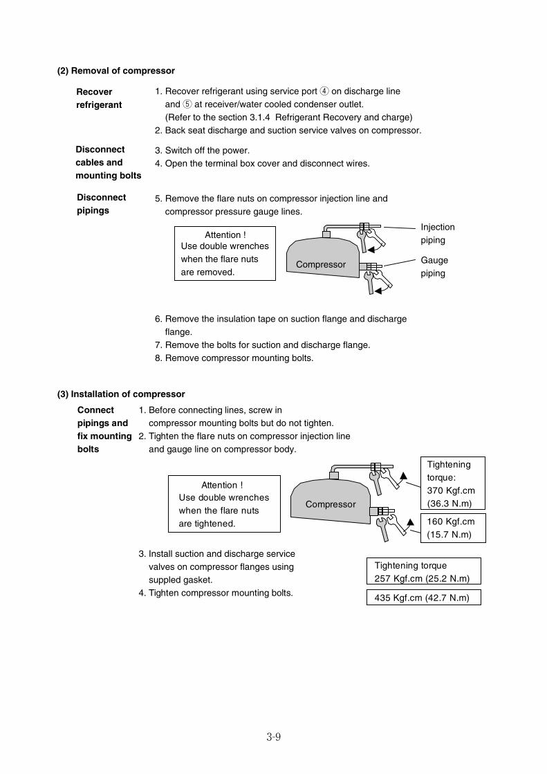
3-9
(2) Removal of compressor
Recoverrefrigerant
Disconnectcables andmounting bolts
Disconnectpipings
1. Recover refrigerant using service port r on discharge line and t at receiver/water cooled condenser outlet. (Refer to the section 3.1.4 Refrigerant Recovery and charge)
2. Back seat discharge and suction service valves on compressor.
3. Switch off the power.4. Open the terminal box cover and disconnect wires.
5. Remove the flare nuts on compressor injection line and compressor pressure gauge lines.
6. Remove the insulation tape on suction flange and discharge flange.
7. Remove the bolts for suction and discharge flange.8. Remove compressor mounting bolts.
Attention !Use double wrencheswhen the flare nutsare removed.
Compressor
Injectionpiping
Gaugepiping
(3) Installation of compressor
Connectpipings andfix mountingbolts
1. Before connecting lines, screw in compressor mounting bolts but do not tighten.
2. Tighten the flare nuts on compressor injection lineand gauge line on compressor body.
3. Install suction and discharge service valves on compressor flanges using suppled gasket.
4. Tighten compressor mounting bolts.
Tightening torque257 Kgf.cm (25.2 N.m)
435 Kgf.cm (42.7 N.m)
Attention !Use double wrencheswhen the flare nutsare tightened.
Tightening torque: 370 Kgf.cm (36.3 N.m)
160 Kgf.cm (15.7 N.m)
Compressor
03_08-24_LXE10E100以降_E.qxd 2015.03.06 9:57 ページ 3-9
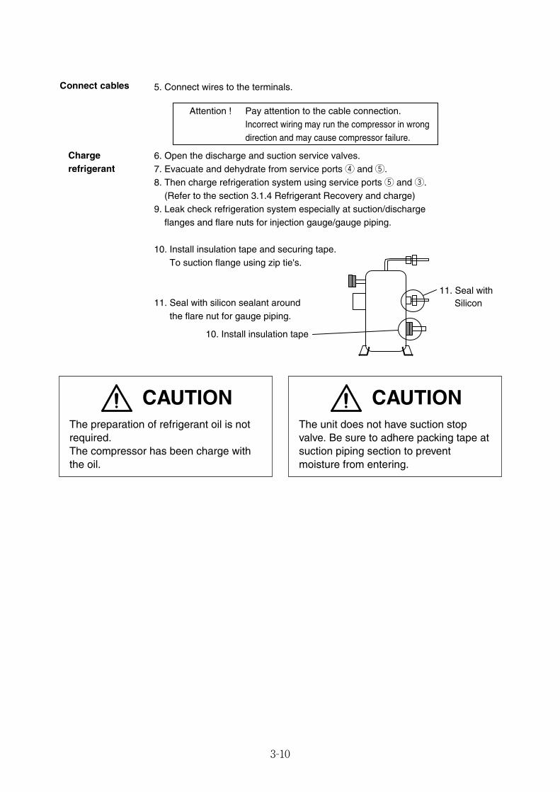
3-10
Chargerefrigerant
6. Open the discharge and suction service valves.7. Evacuate and dehydrate from service ports r and t.8. Then charge refrigeration system using service ports t and e.
(Refer to the section 3.1.4 Refrigerant Recovery and charge) 9. Leak check refrigeration system especially at suction/discharge
flanges and flare nuts for injection gauge/gauge piping.
10. Install insulation tape and securing tape.To suction flange using zip tie's.
11. Seal with silicon sealant around the flare nut for gauge piping.
11. Seal with Silicon
10. Install insulation tape
Attention ! Pay attention to the cable connection. Incorrect wiring may run the compressor in wrong direction and may cause compressor failure.
Connect cables 5. Connect wires to the terminals.
CAUTIONThe unit does not have suction stopvalve. Be sure to adhere packing tape atsuction piping section to preventmoisture from entering.
CAUTIONThe preparation of refrigerant oil is notrequired.The compressor has been charge withthe oil.
03_08-24_LXE10E100以降_E.qxd 2015.03.06 9:57 ページ 3-10
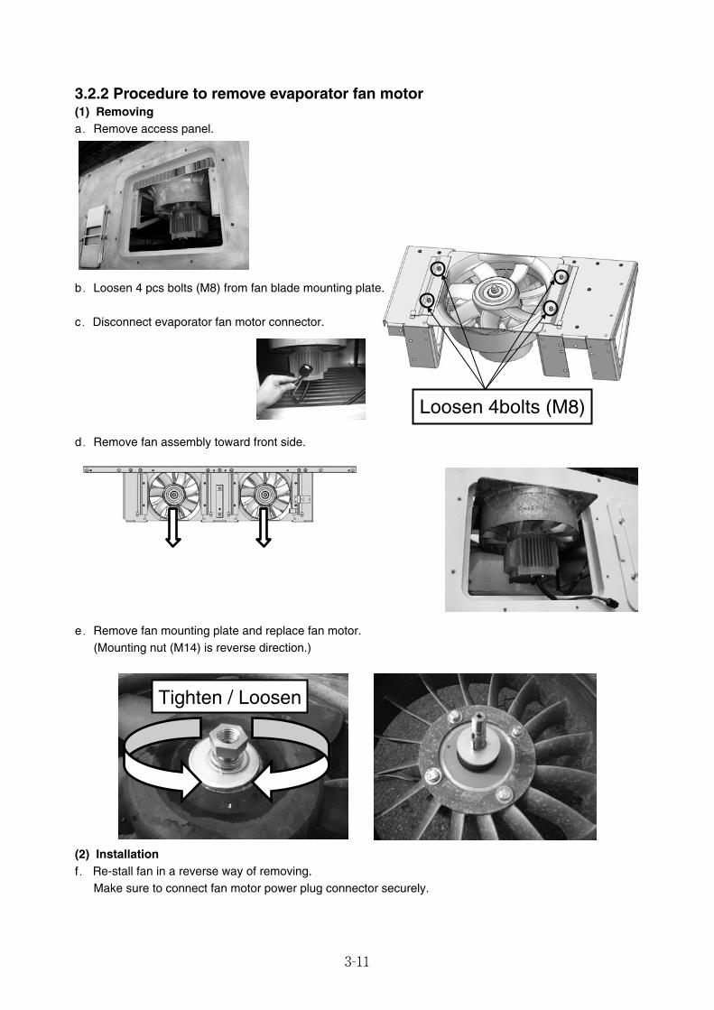
3-11
3.2.2 Procedure to remove evaporator fan motor(1) Removinga.Remove access panel.
Loosen 4bolts (M8)
b.Loosen 4 pcs bolts (M8) from fan blade mounting plate.
c.Disconnect evaporator fan motor connector.
d.Remove fan assembly toward front side.
e.Remove fan mounting plate and replace fan motor.(Mounting nut (M14) is reverse direction.)
Tighten / Loosen
(2) Installationf. Re-stall fan in a reverse way of removing.
Make sure to connect fan motor power plug connector securely.
03_08-24_LXE10E100以降_E.qxd 2015.03.06 9:57 ページ 3-11
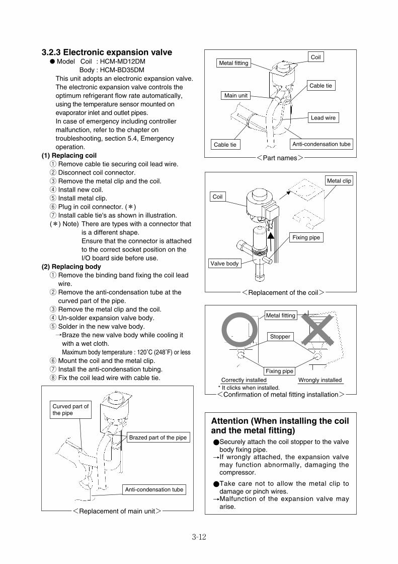
3-12
3.2.3 Electronic expansion valve● Model Coil : HCM-MD12DM
Body : HCM-BD35DMThis unit adopts an electronic expansion valve.The electronic expansion valve controls theoptimum refrigerant flow rate automatically,using the temperature sensor mounted onevaporator inlet and outlet pipes.In case of emergency including controllermalfunction, refer to the chapter ontroubleshooting, section 5.4, Emergencyoperation.
(1) Replacing coilq Remove cable tie securing coil lead wire.w Disconnect coil connector.e Remove the metal clip and the coil.r Install new coil.t Install metal clip.y Plug in coil connector. (*)u Install cable tie's as shown in illustration.(*) Note) There are types with a connector that
is a different shape.Ensure that the connector is attachedto the correct socket position on theI/O board side before use.
(2) Replacing bodyq Remove the binding band fixing the coil lead
wire.w Remove the anti-condensation tube at the
curved part of the pipe.e Remove the metal clip and the coil.r Un-solder expansion valve body.t Solder in the new valve body.→Braze the new valve body while cooling it
with a wet cloth.Maximum body temperature : 120˚C (248˚F) or less
y Mount the coil and the metal clip.u Install the anti-condensation tubing.i Fix the coil lead wire with cable tie.
<Part names>
Metal fitting
Cable tie
Cable tie
Coil
Main unit
Lead wire
Anti-condensation tube
<Replacement of the coil>
Metal clip
Fixing pipe
Coil
Valve body
<Confirmation of metal fitting installation>
Metal fitting
Stopper
Correctly installed Wrongly installed* It clicks when installed.
Fixing pipe
<Replacement of main unit>
Brazed part of the pipe
Anti-condensation tube
Curved part of the pipe
Attention (When installing the coiland the metal fitting)●Securely attach the coil stopper to the valve
body fixing pipe.→If wrongly attached, the expansion valve
may function abnormally, damaging thecompressor.
●Take care not to allow the metal clip todamage or pinch wires.→Malfunction of the expansion valve may
arise.
03_08-24_LXE10E100以降_E.qxd 2015.03.06 9:57 ページ 3-12
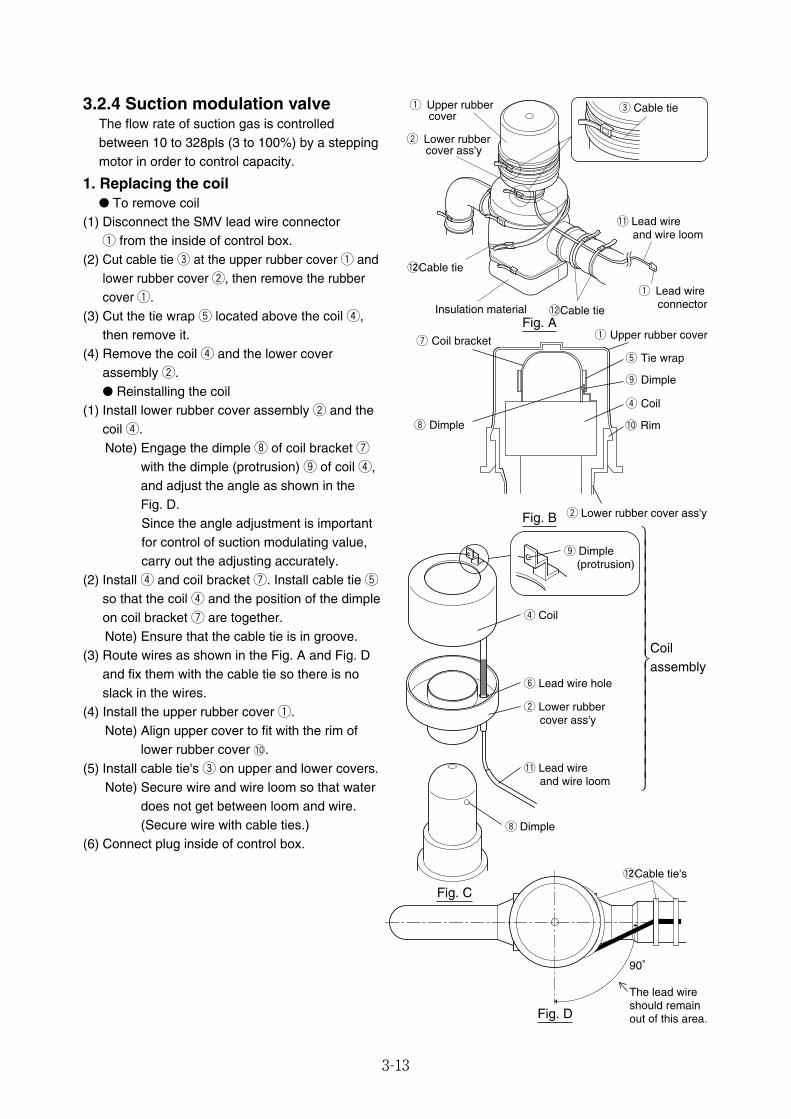
3-13
3.2.4 Suction modulation valveThe flow rate of suction gas is controlledbetween 10 to 328pls (3 to 100%) by a steppingmotor in order to control capacity.
1. Replacing the coil● To remove coil
(1) Disconnect the SMV lead wire connector q from the inside of control box.
(2) Cut cable tie e at the upper rubber cover q andlower rubber cover w, then remove the rubbercover q.
(3) Cut the tie wrap t located above the coil r,then remove it.
(4) Remove the coil r and the lower coverassembly w.● Reinstalling the coil
(1) Install lower rubber cover assembly w and thecoil r.Note) Engage the dimple i of coil bracket u
with the dimple (protrusion) o of coil r,and adjust the angle as shown in the Fig. D.Since the angle adjustment is importantfor control of suction modulating value,carry out the adjusting accurately.
(2) Install r and coil bracket u. Install cable tie tso that the coil r and the position of the dimpleon coil bracket u are together.Note) Ensure that the cable tie is in groove.
(3) Route wires as shown in the Fig. A and Fig. Dand fix them with the cable tie so there is noslack in the wires.
(4) Install the upper rubber cover q.Note) Align upper cover to fit with the rim of
lower rubber cover !0.(5) Install cable tie's e on upper and lower covers.
Note) Secure wire and wire loom so that waterdoes not get between loom and wire.(Secure wire with cable ties.)
(6) Connect plug inside of control box.
r Coil
o Dimple (protrusion)
y Lead wire hole
w Lower rubber cover ass'y
!1 Lead wire and wire loom
i Dimple
The lead wire should remain out of this area.
90°
!22Cable tie's
Coilassembly
!2Cable tie
e Cable tie
!1 Lead wire and wire loom
Insulation material
w Lower rubber cover ass'y
q Upper rubber cover
q Lead wire connector
!22Cable tie
u Coil bracket
i Dimple
q Upper rubber cover
t Tie wrap
o Dimple
r Coil
!0 Rim
w Lower rubber cover ass'y
Fig. A
Fig. B
Fig. C
Fig. D
⎫⎪⎪⎪⎪⎪⎪⎪⎪⎬⎪⎪⎪⎪⎪⎪⎪⎪⎭
03_08-24_LXE10E100以降_E.qxd 2015.03.06 9:57 ページ 3-13
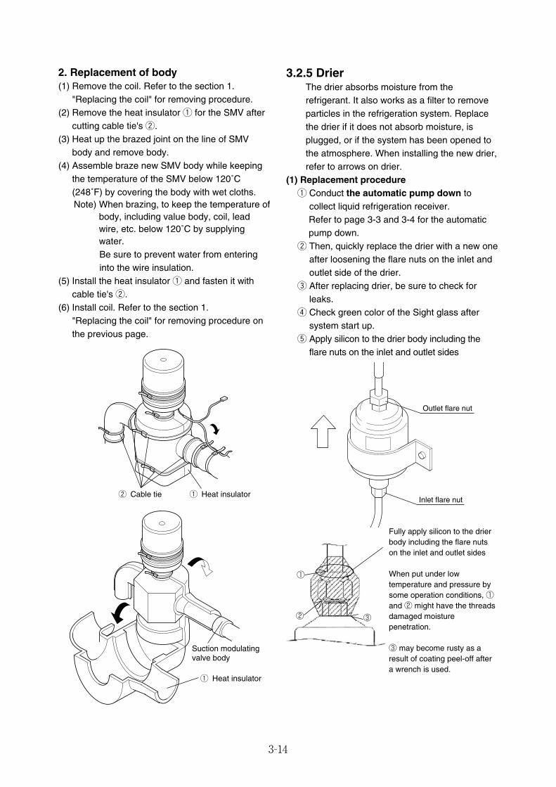
3-14
2. Replacement of body(1) Remove the coil. Refer to the section 1.
"Replacing the coil" for removing procedure.(2) Remove the heat insulator q for the SMV after
cutting cable tie's w.(3) Heat up the brazed joint on the line of SMV
body and remove body.(4) Assemble braze new SMV body while keeping
the temperature of the SMV below 120˚C(248˚F) by covering the body with wet cloths.Note) When brazing, to keep the temperature of
body, including value body, coil, leadwire, etc. below 120˚C by supplyingwater.Be sure to prevent water from enteringinto the wire insulation.
(5) Install the heat insulator q and fasten it withcable tie's w.
(6) Install coil. Refer to the section 1. "Replacing the coil" for removing procedure onthe previous page.
w Cable tie q Heat insulator
q Heat insulator
Suction modulatingvalve body
3.2.5 DrierThe drier absorbs moisture from therefrigerant. It also works as a filter to removeparticles in the refrigeration system. Replacethe drier if it does not absorb moisture, isplugged, or if the system has been opened tothe atmosphere. When installing the new drier,refer to arrows on drier.
(1) Replacement procedureq Conduct the automatic pump down to
collect liquid refrigeration receiver.Refer to page 3-3 and 3-4 for the automaticpump down.
w Then, quickly replace the drier with a new oneafter loosening the flare nuts on the inlet andoutlet side of the drier.
e After replacing drier, be sure to check forleaks.
r Check green color of the Sight glass aftersystem start up.
t Apply silicon to the drier body including theflare nuts on the inlet and outlet sides
Outlet flare nut
Inlet flare nut
①
② ③
Fully apply silicon to the drierbody including the flare nutson the inlet and outlet sides
When put under lowtemperature and pressure bysome operation conditions, ①and ② might have the threadsdamaged moisturepenetration.
③ may become rusty as aresult of coating peel-off aftera wrench is used.
03_08-24_LXE10E100以降_E.qxd 2015.03.06 9:57 ページ 3-14
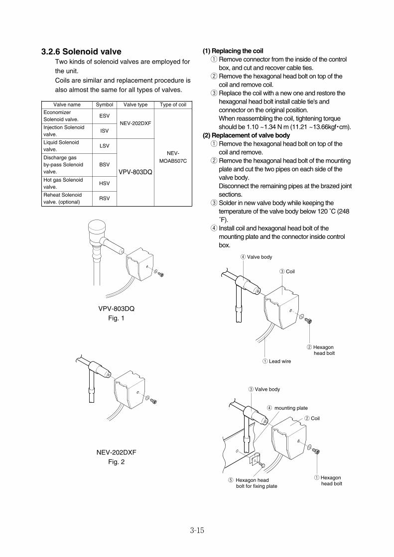
3-15
3.2.6 Solenoid valveTwo kinds of solenoid valves are employed forthe unit.Coils are similar and replacement procedure isalso almost the same for all types of valves.
VPV-803DQFig. 1
NEV-202DXFFig. 2
Valve name Symbol Valve type Type of coil
EconomizerSolenoid valve.
ESVNEV-202DXF
NEV-
MOAB507C
Injection Solenoidvalve.
ISV
Discharge gas by-pass Solenoidvalve.
BSV
Liquid Solenoidvalve.
LSV
Hot gas Solenoidvalve.
HSV
Reheat Solenoidvalve. (optional)
RSV
(1) Replacing the coilq Remove connector from the inside of the control
box, and cut and recover cable ties.w Remove the hexagonal head bolt on top of the
coil and remove coil.e Replace the coil with a new one and restore the
hexagonal head bolt install cable tie's andconnector on the original position.When reassembling the coil, tightening torqueshould be 1.10 ~1.34 N m (11.21 ~13.66kgf・cm).
(2) Replacement of valve bodyq Remove the hexagonal head bolt on top of the
coil and remove.w Remove the hexagonal head bolt of the mounting
plate and cut the two pipes on each side of thevalve body.Disconnect the remaining pipes at the brazed jointsections.
e Solder in new valve body while keeping thetemperature of the valve body below 120 ˚C (248˚F).
r Install coil and hexagonal head bolt of themounting plate and the connector inside controlbox.
w Hexagon head bolt
q Lead wire
r Valve body
e Coil
t Hexagon head bolt for fixing plate
q Hexagon head bolt
w Coil
e Valve body
r mounting plate
VPV-803DQ
03_08-24_LXE10E100以降_E.qxd 2015.03.06 9:57 ページ 3-15

3-16
Protection cap
Discharge pressureregulating valve body
3.2.7 Discharge pressure regulating valve● Model KVR15
(1) Valve replacementq Remove the protection cap to conduct brazing
for the valve body.Be sure not to turn the regulating screw insidethe valve, since the pressure has beenadjusted to 690 kPa (7.0 kg/cm2).
w When brazing, it is required to keep the valvebody below 140 ˚C by covering the body withwet cloth.
e After brazing install and tighten the protectioncap.The tightening torque should be 8 to 10 N � m.Apply lock-tight, etc. on the screw section toavoid loosening of the cap.
r Leak check refrigeration system.
3.2.8 Check valve● Model LCVP11-5D [LCV(B)5 is available]
(1) Replacement procedureq Remove refrigerant line clamp at check
valve, then un-solder valve.w Install the new check valve taking care to
install it in the correct direction, which is thesame direction as the arrow shown illustratedbelow.
e While brazing keep valve cool below 120 ˚C(248 ˚F) with a wet cloth.
r After replacing the valve, Leak checkrefrigeration system.
Suctionmodulation valve
Check valve
Compressor
03_08-24_LXE10E100以降_E.qxd 2015.03.06 9:57 ページ 3-16
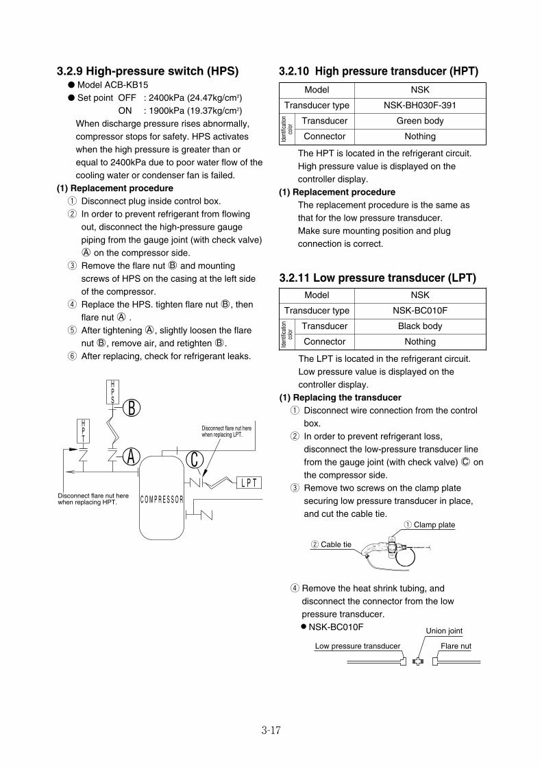
3-17
3.2.9 High-pressure switch (HPS)● Model ACB-KB15● Set point OFF : 2400kPa (24.47kg/cm2)
ON : 1900kPa (19.37kg/cm2)When discharge pressure rises abnormally,compressor stops for safety. HPS activateswhen the high pressure is greater than orequal to 2400kPa due to poor water flow of thecooling water or condenser fan is failed.
(1) Replacement procedureq Disconnect plug inside control box.w In order to prevent refrigerant from flowing
out, disconnect the high-pressure gaugepiping from the gauge joint (with check valve)○A on the compressor side.
e Remove the flare nut ○B and mountingscrews of HPS on the casing at the left sideof the compressor.
r Replace the HPS. tighten flare nut ○B , thenflare nut ○A .
t After tightening ○A , slightly loosen the flarenut ○B , remove air, and retighten ○B .
y After replacing, check for refrigerant leaks.
C O M P R E S S O R
L P T
L
Disconnect flare nut here when replacing HPT.
Disconnect flare nut herewhen replacing LPT.
CTPH
B
A
SPH
3.2.11 Low pressure transducer (LPT)
The LPT is located in the refrigerant circuit.Low pressure value is displayed on thecontroller display.
(1) Replacing the transducerq Disconnect wire connection from the control
box.w In order to prevent refrigerant loss,
disconnect the low-pressure transducer linefrom the gauge joint (with check valve) ○C onthe compressor side.
e Remove two screws on the clamp platesecuring low pressure transducer in place,and cut the cable tie.
r Remove the heat shrink tubing, anddisconnect the connector from the lowpressure transducer.¡NSK-BC010F
Flare nut
Union joint
Low pressure transducer
Model NSK
Transducer type NSK-BC010F
Iden
tifica
tion
color
Transducer Black body
Connector Nothing
q Clamp plate
w Cable tie
3.2.10 High pressure transducer (HPT)
The HPT is located in the refrigerant circuit.High pressure value is displayed on thecontroller display.
(1) Replacement procedureThe replacement procedure is the same asthat for the low pressure transducer.Make sure mounting position and plugconnection is correct.
Model NSK
Transducer type NSK-BH030F-391
Iden
tifica
tion
color
Transducer Green body
Connector Nothing
03_08-24_LXE10E100以降_E.qxd 2015.03.06 9:57 ページ 3-17
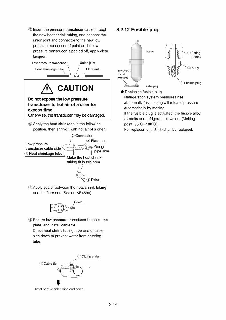
3-18
y Apply the heat shrinkage in the followingposition, then shrink it with hot air of a drier.
u Apply sealer between the heat shrink tubingand the flare nut. (Sealer :KE4898)
i Secure low pressure transducer to the clampplate, and install cable tie.Direct heat shrink tubing tube end of cableside down to prevent water from enteringtube.
r Drier
Make the heat shrink tubing fit in this area
Gaugepipe side
Low pressuretransducer cable sideq Heat shrinkage tube
w Connectore Flare nut
Sealer
● Replacing fusible plugRefrigeration system pressures riseabnormally fusible plug will release pressureautomatically by melting.If the fusible plug is activated, the fusible alloyq melts and refrigerant blows out (Meltingpoint: 95˚C ~100˚C).For replacement, q-e shall be replaced.
3.2.12 Fusible plug
q Fitting mount
w Body
e Fusible plug
Receiver
Service port(Liquidpressure)
Fusible plug
q Clamp plate
Direct heat shrink tubing end down
w Cable tie
CAUTIONDo not expose the low pressuretransducer to hot air of a drier forexcess time.Otherwise, the transducer may be damaged.
t Insert the pressure transducer cable throughthe new heat shrink tubing, and connect theunion joint and connector to the new lowpressure transducer. If paint on the lowpressure transducer is peeled off, apply clearlacquer.
Flare nut
Union jointLow pressure transducer
Heat shrinkage tube
03_08-24_LXE10E100以降_E.qxd 2015.03.06 9:57 ページ 3-18
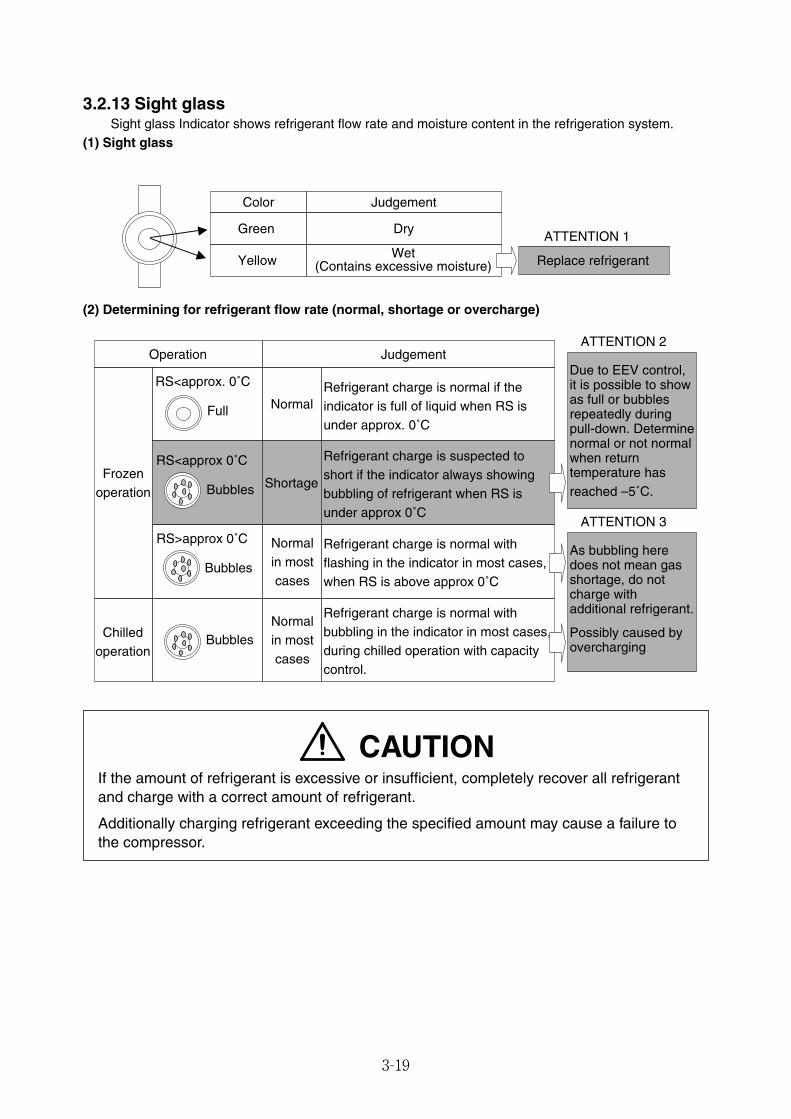
3-19
3.2.13 Sight glassSight glass Indicator shows refrigerant flow rate and moisture content in the refrigeration system.
(1) Sight glass
(2) Determining for refrigerant flow rate (normal, shortage or overcharge)
Color
Green
Judgement
Dry
Yellow Wet(Contains excessive moisture) Replace refrigerant
ATTENTION 1
Judgement
Frozenoperation
Operation
RS<approx. 0˚C
Full
Refrigerant charge is normal if theindicator is full of liquid when RS is under approx. 0˚C
RS<approx 0˚C
Bubbles
Normal
Refrigerant charge is suspected to short if the indicator always showing bubbling of refrigerant when RS is under approx 0˚C
Shortage
RS>approx 0˚C
Bubbles
Normalin mostcases
Refrigerant charge is normal with flashing in the indicator in most cases,when RS is above approx 0˚C
Chilledoperation
BubblesNormalin mostcases
Refrigerant charge is normal withbubbling in the indicator in most cases,during chilled operation with capacitycontrol.
As bubbling heredoes not mean gasshortage, do notcharge withadditional refrigerant.
ATTENTION 3
Due to EEV control, it is possible to show as full or bubbles repeatedly during pull-down. Determine normal or not normal when return temperature has reached –5˚C.
ATTENTION 2
Possibly caused byovercharging
CAUTIONIf the amount of refrigerant is excessive or insufficient, completely recover all refrigerantand charge with a correct amount of refrigerant.
Additionally charging refrigerant exceeding the specified amount may cause a failure tothe compressor.
03_08-24_LXE10E100以降_E.qxd 2015.03.06 9:57 ページ 3-19
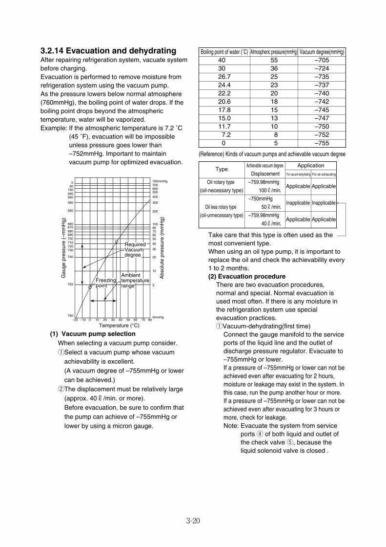
3-20
RequiredVacuumdegree
Freezingpoint
Ambienttemperaturerange
–20 –10 0 10 20 30 40 50 60 70 80
Temperature (°C)
060
160260360
460
560
660670680690700710720730
740
755
760
Gau
ge p
ress
ure
(–m
mH
g)
Abs
olut
e pr
essu
re (
mm
Hg)
760mmHg700600500400
300
200
10090706050
40
30
20
10
5
0mmHg
3.2.14 Evacuation and dehydratingAfter repairing refrigeration system, vacuate systembefore charging.Evacuation is performed to remove moisture fromrefrigeration system using the vacuum pump.As the pressure lowers below normal atmosphere(760mmHg), the boiling point of water drops. If theboiling point drops beyond the atmospherictemperature, water will be vaporized.Example: If the atmospheric temperature is 7.2 ˚C
(45 ˚F), evacuation will be impossibleunless pressure goes lower than–752mmHg. Important to maintainvacuum pump for optimized evacuation.
(1) Vacuum pump selectionWhen selecting a vacuum pump consider.qSelect a vacuum pump whose vacuum
achievability is excellent.(A vacuum degree of –755mmHg or lowercan be achieved.)
wThe displacement must be relatively large(approx. 40r/min. or more).Before evacuation, be sure to confirm thatthe pump can achieve of –755mmHg orlower by using a micron gauge.
Boiling point of water (˚C) Atmospheric pressure(mmHg) Vacuum degree(mmHg)40 55 –70530 36 –72426.7 25 –73524.4 23 –73722.2 20 –74020.6 18 –74217.8 15 –74515.0 13 –74711.7 10 –750
7.2 8 –7520 5 –755
Take care that this type is often used as themost convenient type.When using an oil type pump, it is important toreplace the oil and check the achievability every1 to 2 months.(2) Evacuation procedure
There are two evacuation procedures,normal and special. Normal evacuation isused most often. If there is any moisture inthe refrigeration system use specialevacuation practices.qVacuum-dehydrating(first time)
Connect the gauge manifold to the serviceports of the liquid line and the outlet ofdischarge pressure regulator. Evacuate to–755mmHg or lower.If a pressure of –755mmHg or lower can not beachieved even after evacuating for 2 hours,moisture or leakage may exist in the system. Inthis case, run the pump another hour or more.If a pressure of –755mmHg or lower can not beachieved even after evacuating for 3 hours ormore, check for leakage.Note: Evacuate the system from service
ports r of both liquid and outlet ofthe check valve t, because theliquid solenoid valve is closed .
(Reference) Kinds of vacuum pumps and achievable vacuum degree
Achievable vacuum degree ApplicationType
Displacement For vacuum-dehydrating For air exhausting
Oil rotary type –759.98mmHgApplicable Applicable
(oil-necessary type) 100r/min.
–750mmHgInapplicable Inapplicable
Oil less rotary type 50r/min.
(oil-unnecessary type) –759.98mmHgApplicable Applicable
40r/min.
03_08-24_LXE10E100以降_E.qxd 2015.03.06 9:57 ページ 3-20
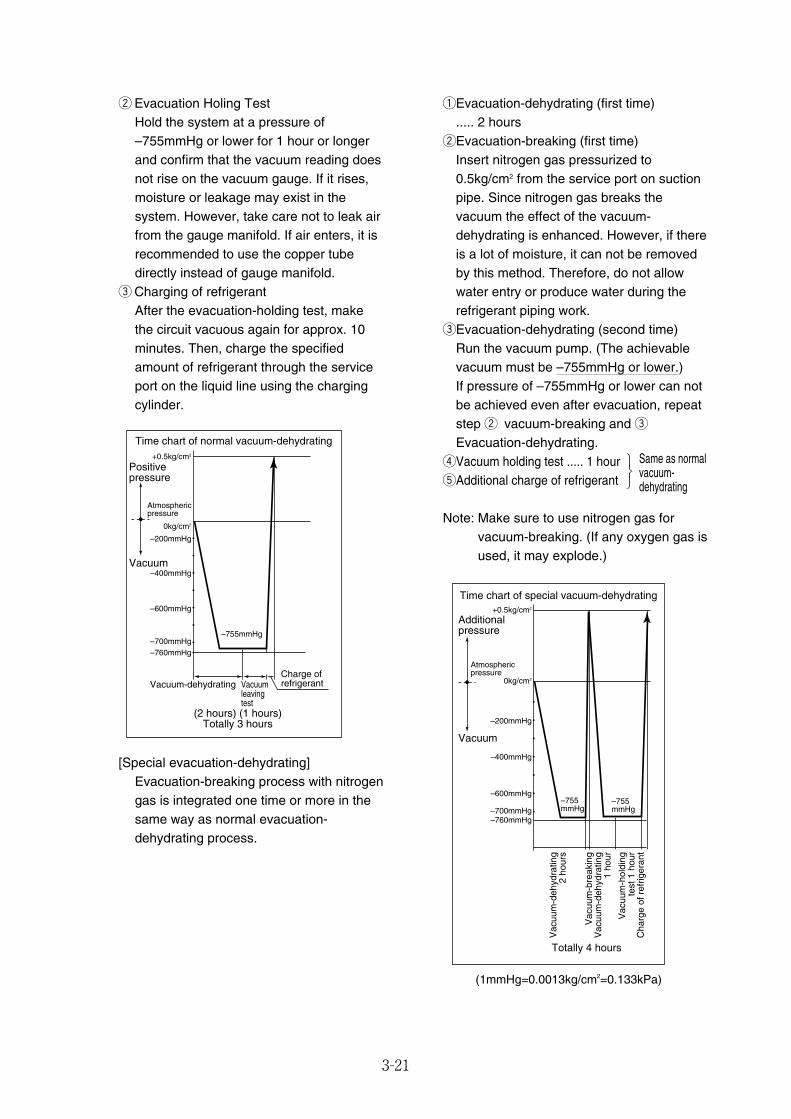
3-21
qEvacuation-dehydrating (first time) ..... 2 hours
wEvacuation-breaking (first time)Insert nitrogen gas pressurized to0.5kg/cm2 from the service port on suctionpipe. Since nitrogen gas breaks thevacuum the effect of the vacuum-dehydrating is enhanced. However, if thereis a lot of moisture, it can not be removedby this method. Therefore, do not allowwater entry or produce water during therefrigerant piping work.
eEvacuation-dehydrating (second time)Run the vacuum pump. (The achievablevacuum must be –755mmHg or lower.)If pressure of –755mmHg or lower can notbe achieved even after evacuation, repeatstep w vacuum-breaking and eEvacuation-dehydrating.
rVacuum holding test ..... 1 hourtAdditional charge of refrigerant
Note: Make sure to use nitrogen gas forvacuum-breaking. (If any oxygen gas isused, it may explode.)
Positivepressure
Atmosphericpressure
Vacuum
Time chart of normal vacuum-dehydrating+0.5kg/cm2
0kg/cm2
–200mmHg
–400mmHg
–600mmHg
–700mmHg–755mmHg
Vacuum-dehydrating Vacuumleaving test
–760mmHg
(2 hours) (1 hours)Totally 3 hours
Charge ofrefrigerant
Additionalpressure
Atmosphericpressure
Vacuum
Time chart of special vacuum-dehydrating+0.5kg/cm2
0kg/cm2
–200mmHg
–400mmHg
–600mmHg
–700mmHg–755mmHg
–755mmHg
Vac
uum
-deh
ydra
ting
2 ho
urs
Vac
uum
-bre
akin
gV
acuu
m-d
ehyd
ratin
g1
hour
Vac
uum
-hol
ding
test
1 h
our
Cha
rge
of r
efrig
eran
t
–760mmHg
Totally 4 hours
(1mmHg=0.0013kg/cm2=0.133kPa)
w Evacuation Holing TestHold the system at a pressure of–755mmHg or lower for 1 hour or longerand confirm that the vacuum reading doesnot rise on the vacuum gauge. If it rises,moisture or leakage may exist in thesystem. However, take care not to leak airfrom the gauge manifold. If air enters, it isrecommended to use the copper tubedirectly instead of gauge manifold.
e Charging of refrigerantAfter the evacuation-holding test, makethe circuit vacuous again for approx. 10minutes. Then, charge the specifiedamount of refrigerant through the serviceport on the liquid line using the chargingcylinder.
[Special evacuation-dehydrating]Evacuation-breaking process with nitrogengas is integrated one time or more in thesame way as normal evacuation-dehydrating process.
Same as normalvacuum-dehydrating
⎫⎬⎭
03_08-24_LXE10E100以降_E.qxd 2015.03.06 9:57 ページ 3-21

No. Inspection item Inspection content 2nd year 4th year 8th year1 Inspect for physical damage2 Loose mounting bolts
3Condition of panels,hinges and locks
1) Cover seal inspection and replacement4 Control box inspection 2) Loose cable gland
3) Internal cleaning
5Casing frame sealing Air leakage and clearanceholes condition
6Seal inspection and Ventilator cover sealsreplacement
1) Compressor
7 Painted area recondition2) Water-cooled condenser/liquid receiver3) Solenoid valve (coil cap)4) Unit frame1) Compressor
8 Repainting2) Water-cooled condenser/liquid receiver3) Condenser fan motor4) Condenser fan
1 Refrigerant leaks2 Compressor Water entering to compressor electrical terminals3 Drier Visual check
4Function inspection andreplacement of Sight glassCondition of refrigerant
5 lines and gauge lines clamp hardware
6Condition of refrigerant line thermal insulation
7Evaporator coil cleaning(BY water)
1) Water-cleaning8 Condenser coil cleaning 2) Steam-cleaning (after pumping
down the refrigerant)
9Water-cooled condenser 1) Water-leakage inspectioninspection 2) Operation of water pressure switch
3-22
3.3 Periodic inspection itemsAlways to operate the unit as specified, conduct periodic inspections of each part in addition to pre-operation and make adjustments or repairs where necessary. The following table shows an example of inspection plan.
Ref
riger
ants
yste
mge
nera
lstr
uctu
re
Note) If you have set the CA unit's on board ON/OFF setting to "ON," refer to the CA service manualfor the Marine type Container Refrigeration Unit.
03_08-24_LXE10E100以降_E.qxd 2015.03.06 9:57 ページ 3-22
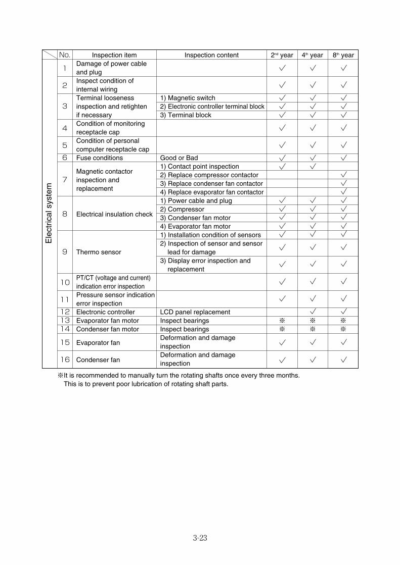
No. Inspection item Inspection content 2nd year 4th year 8th year
1Damage of power cableand plug
2Inspect condition of internal wiringTerminal looseness 1) Magnetic switch
3 inspection and retighten 2) Electronic controller terminal blockif necessary 3) Terminal block
4Condition of monitoringreceptacle cap
5Condition of personalcomputer receptacle cap
6 Fuse conditions Good or Bad
Magnetic contactor 1) Contact point inspection
7 inspection and 2) Replace compressor contactor
replacement3) Replace condenser fan contactor4) Replace evaporator fan contactor1) Power cable and plug
8 Electrical insulation check2) Compressor3) Condenser fan motor4) Evaporator fan motor1) Installation condition of sensors2) Inspection of sensor and sensor
9 Thermo sensor lead for damage3) Display error inspection and
replacement
10PT/CT (voltage and current)indication error inspection
11Pressure sensor indicationerror inspection
12 Electronic controller LCD panel replacement13 Evaporator fan motor Inspect bearings ※ ※ ※14 Condenser fan motor Inspect bearings ※ ※ ※
15 Evaporator fanDeformation and damageinspection
16 Condenser fanDeformation and damageinspection
3-23
Ele
ctric
alsy
stem
※It is recommended to manually turn the rotating shafts once every three months. This is to prevent poor lubrication of rotating shaft parts.
03_08-24_LXE10E100以降_E.qxd 2015.03.06 9:57 ページ 3-23
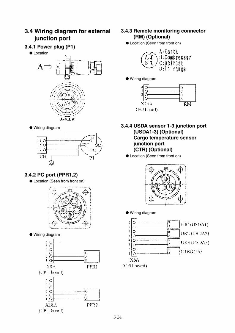
3-24
3.4 Wiring diagram for externaljunction port
3.4.1 Power plug (P1)● Location
● Wiring diagram
3.4.2 PC port (PPR1,2)● Location (Seen from front on)
● Wiring diagram
3.4.3 Remote monitoring connector(RM) (Optional)
● Location (Seen from front on)
● Wiring diagram
3.4.4 USDA sensor 1-3 junction port (USDA1-3) (Optional)Cargo temperature sensorjunction port(CTR) (Optional)
● Location (Seen from front on)
● Wiring diagram
03_08-24_LXE10E100以降_E.qxd 2015.03.06 9:57 ページ 3-24
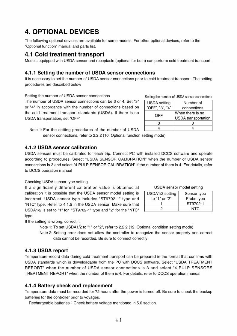
4-1
4.1 Cold treatment transportModels equipped with USDA sensor and receptacle (optional for both) can perform cold treatment transport.
4.1.1 Setting the number of USDA sensor connectionsIt is necessary to set the number of USDA sensor connections prior to cold treatment transport. The settingprocedures are described below
Setting the number of USDA sensor connectionsThe number of USDA sensor connections can be 3 or 4. Set "3"or "4" in accordance with the number of connections based onthe cold treatment transport standards (USDA). If there is noUSDA transportation, set "OFF"
Note 1: For the setting procedures of the number of USDAsensor connections, refer to 2.2.2 (10. Optional function setting mode)
4.1.2 USDA sensor calibrationUSDA sensors must be calibrated for each trip. Connect PC with installed DCCS software and operateaccording to procedures. Select "USDA SENSOR CALIBRATION" when the number of USDA sensorconnections is 3 and select "4 PULP SENSOR CALIBRATION" if the number of them is 4. For details, referto DCCS operation manual
Checking USDA sensor type setting If a significantly different calibration value is obtained atcalibration it is possible that the USDA sensor model setting isincorrect. USDA sensor type includes "ST9702-1" type and"NTC" type. Refer to 4.1.5 in the USDA sensor. Make sure thatUSDA1/2 is set to "1" for "ST9702-1" type and "2" for the "NTC"type.If the setting is wrong, correct it.
Note 1: To set USDA1/2 to "1" or "2", refer to 2.2.2 (12. Optional condition setting mode) Note 2: Setting error does not allow the controller to recognize the sensor property and correct
data cannot be recorded. Be sure to connect correctly
4.1.3 USDA reportTemperature record data during cold treatment transport can be prepared in the format that confirms withUSDA standards which is downloadable from the PC with DCCS software. Select "USDA TREATMENTREPORT" when the number of USDA sensor connections is 3 and select "4 PULP SENSORSTREATMENT REPORT" when the number of them is 4. For details, refer to DCCS operation manual
4.1.4 Battery check and replacementTemperature data must be recorded for 72 hours after the power is turned off. Be sure to check the backupbatteries for the controller prior to voyages.
Rechargeable batteries:Check battery voltage mentioned in 5.6 section.
Setting the number of USDA sensor connections
USDA setting"OFF", "3", "4"
Number ofconnections
3 34 4
OFFWhen there is noUSDA transportation
USDA sensor model setting
USDA1/2 settingto "1" or "2"
Sensor typeProbe type
2 NTC1 ST9702-1
4. OPTIONAL DEVICESThe following optional devices are available for some models. For other optional devices, refer to the"Optional function" manual and parts list.
04_01-11_LXE10E100以降_E.qxd 2015.03.06 10:34 ページ 4-1
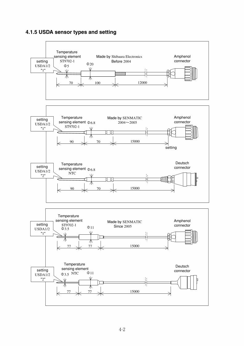
4-2
4.1.5 USDA sensor types and setting
Before 2004
Made by SENMATIC2004~2005
Made by SENMATICSince 2005
setting USDA1/2
"1"
setting USDA1/2
"1"
setting USDA1/2
"2"
settingUSDA1/2
"1"
settingUSDA1/2
"2"
Temperature sensing element
ST9702-1Made by Shibaura Electronics
Temperature sensing element
ST9702-1
Temperature sensing element
ST9702-1
Temperature sensing element
NTC
Temperature sensing element
NTC
Amphenolconnector
Amphenolconnector
Amphenolconnector
Deutschconnector
Deutschconnector
Ф5 Ф20
70 100 12000
Ф6.8
Ф6.8
7090 15000
7090 15000
7777 15000
Ф3.5
Ф3.5
Ф11
7777 15000
Ф11
setting
04_01-11_LXE10E100以降_E.qxd 2015.03.06 10:34 ページ 4-2
4-3
●Type: 5ZZ2157Consisting of the body (wire reel and positionmeter) and the wire. The top of the wire isconnected to the ventilator outlet cover so thatthe ventilator outlet opening can be detected.
Setting methodTo validate the venti lator outlet openingdetection function, it is necessary to configurethe settings in accordance with the installationpositions of the ventilator outlet in the "basicfunction setting mode" mentioned below
OFF : Detection function not availableH : Detection function available at the upper ventilator openingL : Detection function available at the lower ventilator opening
FA SEN
Make selection using the
key and key. Press the
key to confirm the selection
LED display LCD display Setting method
Compressor unloadersystem setting
S
Setting of dehumidificationcoil available or not available
S
Detection of ventilation amount (FA log) function setting
11. Basic function setting mode
Set to "H"
Set to "L"
Ventilatoroutlet cover
Control box
FA sensor
LED part
LCD part
4.2 Ventilator outlet opening detection(FA sensor)
04_01-11_LXE10E100以降_E.qxd 2015.03.06 10:34 ページ 4-3

4-4
FA sensor calibration (zero point adjustment)To set ventilation amount (FA amount), calibrate (zero point adjustment) the ventilator outlet cover and theFA sensor display value in advance in accordance with the steps below.
1. Calibration of ventilation coverCalibrate the ventilator outlet coverin accordance with 3 steps (fullyopen⇒ ful ly closed⇒ zero pointadjustment) mentioned at the right.
2. Calibration of FA sensor display valueAfter the completion of the ventilator outlet cover calibration, move to the FA sensor display valuecalibration. To calibrate, refer to "FA calibration" in the manual check selection mode (P. 2-35, 2.5.2.4M. CHECK).
When a certain value is displayedas a FA sensor value in the step 3("5"m3/h at the right column),press and hold the ENTER keyfor 3 seconds to reset the FAvalue to "0"m3/h. Then switch unitOFF.
Ventilation amount setting
(FA amount)After the completion of calibrationmentioned above, first fully openventilator outlet cover and close itgradually so that the FA amount valuecan be set. Then tighten 4 wing bolts. Display the FA amount in accordancewith section 6. Sensor indicationmode (P. 2-12) or 3. Battery mode (P.2-9). Note: FA sensor position is determinedby the ventilator outlet cover openingor closing. To display accurate FAamount, as mentioned above, fullyopen the cover f irst and close itgradually.
Step 1.Step1. Fully open
the ventilation cover.
Step 3.Lift up the cover a little
to make zero point adjustment. After that, tighten 4 butterfly nuts.
Step 2.Fully close the
ventilation cover.
FA intake port
Ventilation cover
zero point
FA outlet port
zero point
Step 2.Setting of FA amount
Step 1.Fully open
Ventilation coverzero point
FA 0
FA air amount display
Maximum FA
FA air amount display
FA 50
FA air amount display
Setting of FA amountIn case of 50m3/h
SP 5.0 SP 5.0SP 5.0
press and hold for 3 seconds
5
FA CAL
0
FA CAL
04_01-11_LXE10E100以降_E.qxd 2015.03.06 10:34 ページ 4-4

4-5
Function description1. Ventilation amount log function
Ventilation amount data can be provided to the controller as an event log
2. Data logging details・Ventilation amount (FA) converted from the ventilator outlet opening degree (indicated in m3/h)・Time, data, month, year for data logging
3. Log timing・When the unit starts to run・Once a day (12:00 am)・When the ventilation outlet opening changes
Replacement method① Remove the lead wire (connector connection) in the control box② Remove the screws that hold the ventilator outlet cover to the top of the wire③ Remove the screws hold the body to the casing and replace sensor assembly including wire* Be sure to replace sensor assembly including the wire
④ After replacing, seal with silicon sealant around the screws holding the position meter in the sensor body
Screws
04_01-11_LXE10E100以降_E.qxd 2015.03.06 10:34 ページ 4-5

4-6
4.3 Daikin Temperature Management System (optional)DTMS functionThis is a temperature control function to reduce power consumption. To conserve energy, this systemcontrols the compressor's ON-OFF switching, High-Low switching for the evaporator fan speed whilemaintaining present temperature control
Control details
*1 Energy-saving control applicable to the frozen mode in DTMS 2*2 Operating range for DTMS 1: -1.0 C̊≦SP≦+30.0 C̊*3 The unit operation is different from normal operation under DTMS operation.
Special instruction for DTMS function1) "1" or "2" is displayed in LCD screen during DTMS operation
2) Operation controlDTMS is not activated for the following cases even if DTMS is set to ON (dFLt)
3) Cancellation of DTMS operationWhen DTMS function is unnecessary for some transportation, cancel the operation in accordance withthe procedures described in the next page. But DTMS function is automatically switched to ON (dFLt) atthe completion of the PTI mentioned below
1) When F-PTI is completed 2) When Chilled PTI is completed 3) When Frozen PTI is completed
DTMS
OFF when the compressor is OFFLow-OFF operation
ON-OFF operation
Chilled mode
Operating range -9.9 C̊≦SP≦-2.6 C̊, -1.0 C̊≦SP≦+30.0 C̊*2
Temperature control range Same as normal chilled operations*2(SP-0.5 C̊≦SS≦SP+0.5 C̊)Compressor ON-OFF operation*3
Evaporator fan motor High-Low-Off switching operation*3
Frozen mode*1
Operating range Whole frozen range(-10.0 C̊≧SP≧-30.0 C̊)Temperature control range Same as normal frozen operations(SP≦RS≦SP+1.0 C̊)CompressorCondenser fan motorEvaporator fan motor
Condenser fan motor OFF when the compressor is OFF
indicates DTMS
Example of screen indication
indicates DTMS
1)During dehumidification operations 7)During automatic PTI8)During high-load operations (chilled mode only)
cycle becomes short6)Out of in-range 9)When protection devices are activated
2)When USDA is set to ON (USDA=3 or 4)3)During pull down operations4)During defrosting operations5)During heating operations
・When there is a huge gap between SS and RS・When the compressor's ON-OFF switching
04_01-11_LXE10E100以降_E.qxd 2015.03.06 10:34 ページ 4-6
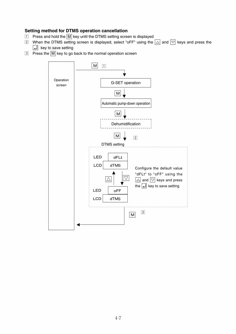
4-7
Setting method for DTMS operation cancellationz Press and hold the M key until the DTMS setting screen is displayedx When the DTMS setting screen is displayed, select "oFF" using the and keys and press the
key to save settingc Press the M key to go back to the normal operation screen
G-SET operation
Automatic pump-down operation
Dehumidification
z
x
S
S
c
DTMS setting
Operation
screen
Configure the default value
"dFLt" to "oFF" using the
and keys and press
the key to save setting
04_01-11_LXE10E100以降_E.qxd 2015.03.06 10:34 ページ 4-7

4-8
4.4 Automatic setpoint change: ASC (optional)ASC functionIt is necessary to change the set temperature over time for some types of cargos. ASC function can specifyset temperature and its duration
For example, as shown below, ASC function allows the set temperatures to change automatically byspecifying in advance first set temperature (SP1) and its duration (TM1), second set temperature (SP2)and its duration (TM2), third set temperature (SP3) and its duration (TM3), pull down and the pull upoperations. For some types of cargoes, dehumidification control settings are configured as well.
z ASC screen and the normal screen alternate every 5 seconds during the in-range controlIn the following example, the second set temperature SP2 (0.0 C̊) and its duration TM2 (14Hr)
x The temperature inside rises gradually (0.5 C̊/Hr) to prevent rapid temperature rise during the pull upoperation
c Up to 9 patterns are available for set temperatures (up to 8 for setting time). There is no duration limitfor the last set temperature
Special instructions for ASC operation1)It is impossible to change the set temperature and set duration during ASC operation.
To change the settings, configure ASC settings to "OFF" and "ON" again.2)When power is turned off (unit off) during ASC operation, ASC operation restarts at next power-on3)The following items are recorded as event log
ASC "ON"/ "OFF", SP1, TM1, dHU1 "ON"/ "OFF", RH1, SP2 ----, SP3 ---4)The last set temperature is displayed on the modem. Settings cannot be changed via the modem5)Cancellation of ASC operation①When configuring ASC to "OFF" ②When F-PTI is completed ③When Custom PTI (Chilled &Frozen) is completed
ASC function starts to operate
Pull down
SP1
Pull down
Pull up
SP2
SP3
Timer TMIstarts TM1 TM2 TM3
xcz
z
z
Control temperaturewhen the second
temperature is set
The second settemperature
The remainingtime for the secondset temperature
The whole durationfor the second settemperature
Normal screen ASC screen
Switching every5 secondsLED
LCD
04_01-11_LXE10E100以降_E.qxd 2015.03.06 10:34 ページ 4-8
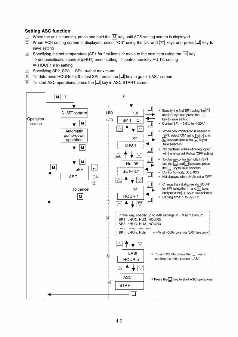
4-9
ONASC
oFF
LED
LCD SP 1 C
1.0
on
dHU 1
Hu 95
SET-HU1
14
HOUR 1
LASt
HOUR n
ASC
START* Press the key to start ASC operations
To set HOURn, press the key toconfirm the initial screen "LASt"*
In this way, specify up to n-th settings. n = 9 at maximum.SP2, dHU2, HU2, HOUR2SP3, dHU3, HU3, HOUR3 ----, ----, ----, ----SPn, dHUn, HUn ----To set HOURn, determine "LASt" (see below)
Not displayed in the unit not equippedwith the reheat coil (Reheat "OFF" setting)
Change the initial screen to HOUR1 for SP1 using the and keys and press the key to save selection Setting time: 1 to 999 Hr
*
*
To change control humidity in SP1use the and keys and pressthe key to save selectionControl humidity: 60 to 95%Not displayed when dHU is set to "OFF"
*
*
* *
*
*
*
When dehumidification is needed in SP1, select "ON" using the and△ keys and press the key to save selection
Specify the first SP1 using the and keys and press the key to save settingControl SP: -9.9℃ to +30℃
cz
x
v
b
n
Operation screen
G - SET operation
Automaticpump-downoperation
To cancel
M
M
M
M
M
M
Setting ASC functionz When the unit is running, press and hold the M key until ACS setting screen is displayedx When ACS setting screen is displayed, select "ON" using the and keys and press key to
save settingc Specifying the set temperature (SP1 for first item) ⇒ move to the next item using the key⇒ dehumidification control (dHU1) on/off setting ⇒ control humidity HU 1% setting⇒ HOUR1 (Hr) setting
v Specifying SP2, SP3.....SPn. n=9 at maximumb To determine HOURn for the last SPn, press the key to go to "LASt" screen
n To start ASC operations, press the key in ASC START screen
04_01-11_LXE10E100以降_E.qxd 2015.03.06 10:34 ページ 4-9
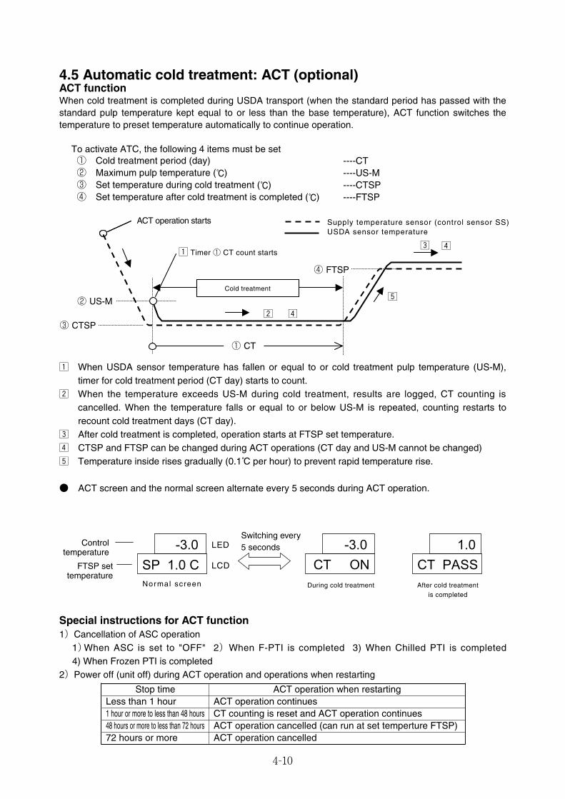
4-10
4.5 Automatic cold treatment: ACT (optional)ACT functionWhen cold treatment is completed during USDA transport (when the standard period has passed with thestandard pulp temperature kept equal to or less than the base temperature), ACT function switches thetemperature to preset temperature automatically to continue operation.
To activate ATC, the following 4 items must be set
z When USDA sensor temperature has fallen or equal to or cold treatment pulp temperature (US-M),timer for cold treatment period (CT day) starts to count.
x When the temperature exceeds US-M during cold treatment, results are logged, CT counting iscancelled. When the temperature falls or equal to or below US-M is repeated, counting restarts torecount cold treatment days (CT day).
c After cold treatment is completed, operation starts at FTSP set temperature.v CTSP and FTSP can be changed during ACT operations (CT day and US-M cannot be changed)b Temperature inside rises gradually (0.1 C̊ per hour) to prevent rapid temperature rise.
● ACT screen and the normal screen alternate every 5 seconds during ACT operation.
Special instructions for ACT function1)Cancellation of ASC operation
1)When ASC is set to "OFF" 2)When F-PTI is completed 3) When Chilled PTI is completed4) When Frozen PTI is completed
2)Power off (unit off) during ACT operation and operations when restarting
① Cold treatment period (day) ----CT② Maximum pulp temperature ( C̊) ----US-M③ Set temperature during cold treatment ( C̊) ----CTSP④ Set temperature after cold treatment is completed ( C̊) ----FTSP
ACT operation starts
② US-M
③ CTSP
z Timer ① CT count starts
Cold treatment
④ FTSP
Supply temperature sensor (control sensor SS)USDA sensor temperature
x v
b
c v
① CT
Controltemperature
FTSP settemperature
Normal screen During cold treatment After cold treatmentis completed
Switching every5 secondsLED
LCD
Stop time ACT operation when restartingLess than 1 hour ACT operation continues1 hour or more to less than 48 hours CT counting is reset and ACT operation continues48 hours or more to less than 72 hours ACT operation cancelled (can run at set temperture FTSP)72 hours or more ACT operation cancelled
04_01-11_LXE10E100以降_E.qxd 2015.03.06 10:34 ページ 4-10
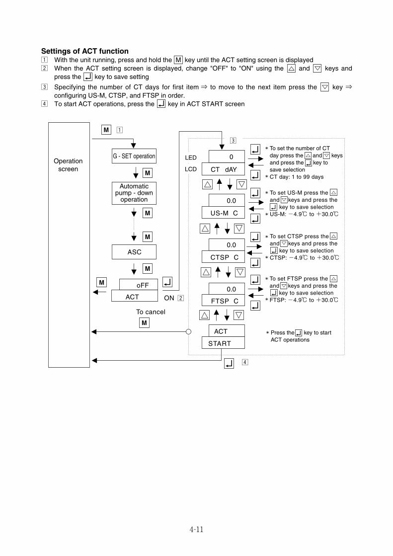
4-11
ASC
ACT
oFF
Operationscreen
G - SET operation
Automaticpump - down
operation
To cancel
ON x
ACT
START
0.0
FTSP C
0.0
CTSP C
0.0
US-M C
0
CT dAY
LED
LCD
c
*
* To set the number of CTday press the and keysand press the key tosave selectionCT day: 1 to 99 days
*
* To set US-M press the and keys and press the key to save selectionUS-M: -4.9℃ to +30.0℃
*
* To set CTSP press the and keys and press the key to save selectionCTSP: -4.9℃ to +30.0℃
*
* To set FTSP press the and keys and press the key to save selectionFTSP: -4.9℃ to +30.0℃
* Press the key to startACT operations
v
zM
M
M
M
M
M
M
Settings of ACT functionz With the unit running, press and hold the M key until the ACT setting screen is displayedx When the ACT setting screen is displayed, change "OFF" to "ON" using the and keys and
press the key to save setting
c Specifying the number of CT days for first item ⇒ to move to the next item press the key ⇒configuring US-M, CTSP, and FTSP in order.
v To start ACT operations, press the key in ACT START screen
04_01-11_LXE10E100以降_E.qxd 2015.03.06 10:34 ページ 4-11
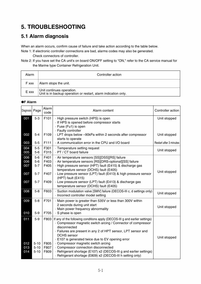
5-1
5. TROUBLESHOOTING
5.1 Alarm diagnosis
When an alarm occurs, confirm cause of failure and take action according to the table below.Note 1: If electronic controller connections are bad, alarms codes may also be generated.
Check connectors of controller.Note 2: If you have set the CA unit's on board ON/OFF setting to "ON," refer to the CA service manual for
the Marine type Container Refrigeration Unit.
Alarm Controller action
F xxx Alarm stops the unit.
E xxx Unit continues operation. Unit is in backup operation or restart, alarm indication only.
●F Alarm
PageDiagnosis Controller actionAlarmcode
Alarm content
004005
5-55-6
F301F315
・Temperature setting request・PT / CT board failure
Unit stopped
006006007
007
007
5-65-65-7
5-7
5-7
F401F403F405
F407
F409
・Air temperature sensors [SS][DSS][RS] failure・Air temperature sensors [RS][DRS-optional][SS] failure・High pressure sensor (HPT) fault (E415) & discharge gas
temperature sensor (DCHS) fault (E405)・Low pressure sensor (LPT) fault (E413) & high pressure sensor
(HPT) fault (E415)・Low pressure sensor (LPT) fault (E413) & discharge gas
temperature sensor (DCHS) fault (E405)
Unit stopped
008 5-8 F603 ・Suction modulation valve [SMV] failure (DECOS-III c, d settings only)・Incorrect controller model setting
Unit stopped
009
010
5-8
5-9
F701
F705
・Main power is greater than 535V or less than 300V within 2 seconds during unit start・Main power frequency abnormality・S phase is open
Unit stopped
001
002
003
5-3
5-4
5-5
F101
F109
F111
・High pressure switch (HPS) is open・If HPS is opened before compressor starts・Fuse (Fu1) is open・Faulty controller・LPT drops below –90kPa within 2 seconds after compressor
starts to operate・A communication error in the CPU and I/O board
Unit stopped
Unit stopped
Restart after 3 minutes
011
012013014
5-9
5-105-105-10
F803
F805F807F809
If any of the following conditions apply (DECOS-III g and earlier settings)・Compressor magnetic switch arcing / Connector of compressor
disconnected・Failures are present in any 2 of HPT sensor, LPT sensor and
DCHS sensor・E107 is generated twice due to EV opening error・Compressor magnetic switch arcing・Compressor connection disconnected・Refrigerant shortage (E107) x2 (DECOS-III g and earlier settings)・Refrigerant shortage (E809) x2 (DECOS-III h setting only)
Unit stopped
05_01-23_LXE10E100以降_E.qxd 2015.03.06 9:59 ページ 5-1
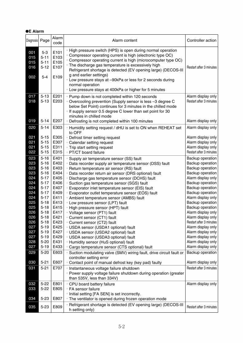
5-2
●E Alarm
PageDiagnosis Controller actionAlarmcode
Alarm content
020
021021021022
5-14
5-155-155-155-15
E303
E305E307E311E315
・Humidity setting request / dHU is set to ON when REHEAT setto OFF・Defrost timer setting request・Calendar setting request・Trip start setting request・PT/CT board failure
Alarm display only
Alarm display onlyAlarm display onlyAlarm display onlyRestart after 3 minutes
001015015016
002
5-35-115-115-12
5-4
E101E103E105E107
E109
・High pressure switch (HPS) is open during normal operation・Compressor operating current is high (electronic type OC)・Compressor operating current is high (microcomputer type OC)・The discharge gas temperature is excessively high
Refrigerant shortage is detected (EV opening large) (DECOS-IIIg and earlier settings)・Low pressure stays at –90kPa or less for 2 seconds during
normal operation・Low pressure stays at 400kPa or higher for 5 minutes
Restart after 3 minutes
029
030
5-20
5-21
E603
E607
・Suction modulating valve (SMV) wiring fault, drive circuit fault orcontroller setting error・Contact point of manual defrost key (key pad) faulty
Backup operation
Alarm display only031 5-21 E707 ・Instantaneous voltage failure shutdown
・Power supply voltage failure shutdown during operation (greaterthan 535V, less than 334V)
Restart after 3 minutes
032033
034
5-225-22
5-23
E801E805
E807
・CPU board battery failure・FA sensor failure・Initial setting [FA SEN] is set incorrectly.・The ventilator is opened during frozen operation mode
Alarm display only
017018
019
5-135-13
5-14
E201E203
E207
・Pump down is not completed within 120 seconds・Overcooling prevention (Supply sensor is less –3 degree C
below Set Point) continues for 3 minutes in the chilled mode・If supply sensor 0.5 degree C lower than set point for 30
minutes in chilled mode・Defrosting is not completed within 100 minutes
Alarm display onlyRestart after 3 minutes
Alarm display only
023023023023024024024024024025025026026026027027027028027
5-165-165-165-165-175-175-175-175-175-185-185-185-185-185-195-195-195-205-19
E401E402E403E404E405E406E407E409E411E413E415E417E421E423E425E427E429E431E433
・Supply air temperature sensor (SS) fault・Data recorder supply air temperature sensor (DSS) fault・Return temperature air sensor (RS) fault・Data recorder return air sensor (DRS optional) fault・Discharge gas temperature sensor (DCHS) fault・Suction gas temperature sensor (SGS) fault・Evaporator inlet temperature sensor (EIS) fault・Evaporator outlet temperature sensor (EOS) fault・Ambient temperature sensor (AMBS) fault・Low pressure sensor (LPT) fault・High pressure sensor (HPT) fault・Voltage sensor (PT1) fault・Current sensor (CT1) fault・Current sensor (CT2) fault・USDA sensor (USDA1 optional) fault・USDA sensor (USDA2 optional) fault・USDA sensor (USDA3 optional) fault・Humidity sensor (HuS optional) fault・Cargo temperature sensor (CTS optional) fault
Backup operationBackup operationBackup operationBackup operationAlarm display onlyBackup operationBackup operationBackup operationAlarm display onlyBackup operationBackup operationAlarm display onlyAlarm display onlyRestart after 3 minutesAlarm display onlyAlarm display onlyAlarm display onlyAlarm display onlyAlarm display only
035 5-23 E809 ・Refrigerant shortage is detected (EV opening large) (DECOS-IIIh setting only)
Restart after 3 minutes
05_01-23_LXE10E100以降_E.qxd 2015.03.06 9:59 ページ 5-2
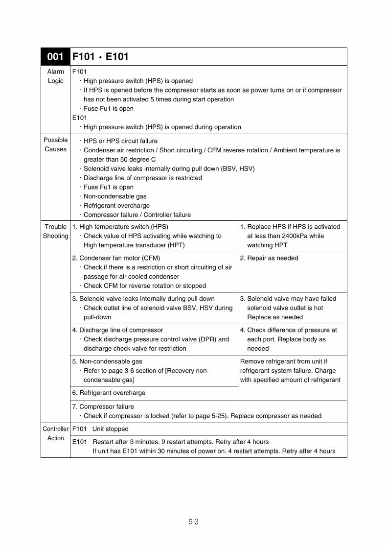
5-3
F101・E101001
ControllerAction
F101 Unit stopped
E101 Restart after 3 minutes. 9 restart attempts. Retry after 4 hoursIf unit has E101 within 30 minutes of power on. 4 restart attempts. Retry after 4 hours
AlarmLogic
F101・High pressure switch (HPS) is opened・If HPS is opened before the compressor starts as soon as power turns on or if compressor
has not been activated 5 times during start operation・Fuse Fu1 is open
E101・High pressure switch (HPS) is opened during operation
PossibleCauses
・HPS or HPS circuit failure・Condenser air restriction / Short circuiting / CFM reverse rotation / Ambient temperature is
greater than 50 degree C・Solenoid valve leaks internally during pull down (BSV, HSV)・Discharge line of compressor is restricted・Fuse Fu1 is open・Non-condensable gas・Refrigerant overcharge・Compressor failure / Controller failure
TroubleShooting
1. High temperature switch (HPS)・Check value of HPS activating while watching to
High temperature transducer (HPT)
1. Replace HPS if HPS is activatedat less than 2400kPa whilewatching HPT
2. Condenser fan motor (CFM)・Check if there is a restriction or short circuiting of air
passage for air cooled condenser・Check CFM for reverse rotation or stopped
2. Repair as needed
3. Solenoid valve leaks internally during pull down・Check outlet line of solenoid valve BSV, HSV during
pull-down
3. Solenoid valve may have failedsolenoid valve outlet is hotReplace as needed
4. Discharge line of compressor・Check discharge pressure control valve (DPR) and
discharge check valve for restriction
4. Check difference of pressure ateach port. Replace body asneeded
5. Non-condensable gas・Refer to page 3-6 section of [Recovery non-
condensable gas]
Remove refrigerant from unit ifrefrigerant system failure. Chargewith specified amount of refrigerant
6. Refrigerant overcharge
7. Compressor failure・Check if compressor is locked (refer to page 5-25). Replace compressor as needed
05_01-23_LXE10E100以降_E.qxd 2015.03.06 9:59 ページ 5-3
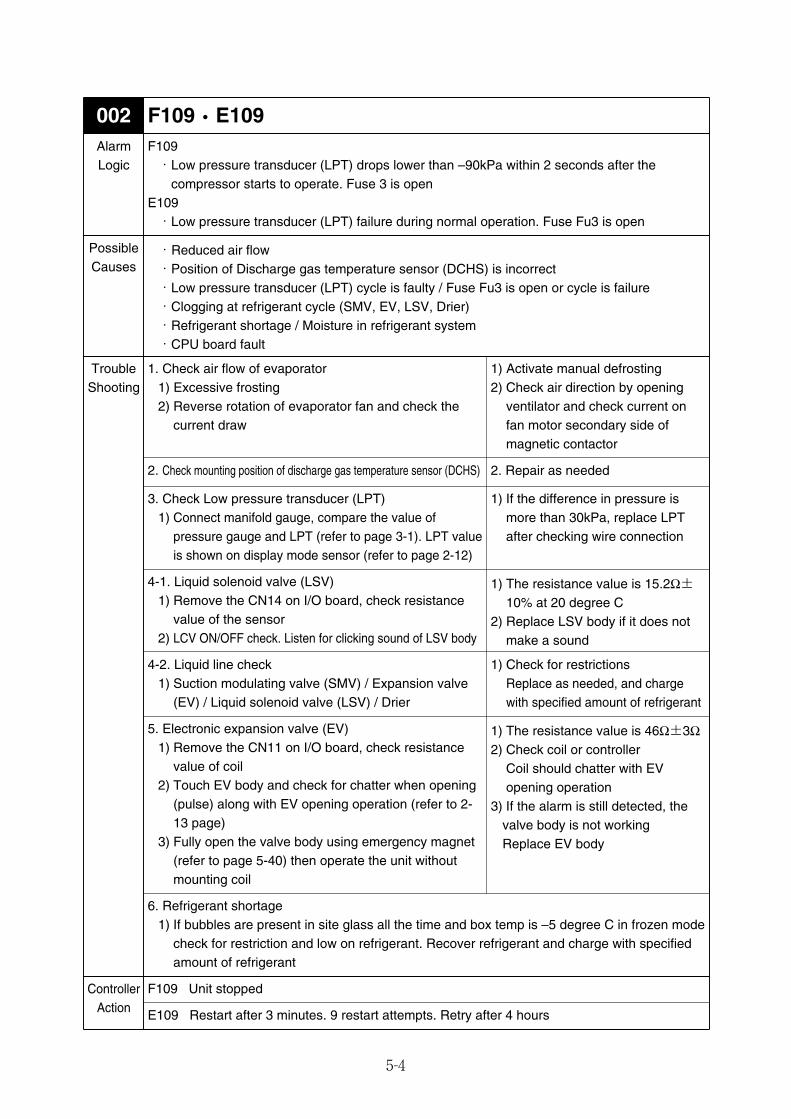
5-4
F109・E109002AlarmLogic
F109・Low pressure transducer (LPT) drops lower than –90kPa within 2 seconds after the
compressor starts to operate. Fuse 3 is openE109・Low pressure transducer (LPT) failure during normal operation. Fuse Fu3 is open
・Reduced air flow・Position of Discharge gas temperature sensor (DCHS) is incorrect・Low pressure transducer (LPT) cycle is faulty / Fuse Fu3 is open or cycle is failure・Clogging at refrigerant cycle (SMV, EV, LSV, Drier)・Refrigerant shortage / Moisture in refrigerant system・CPU board fault
1. Check air flow of evaporator1) Excessive frosting2) Reverse rotation of evaporator fan and check the
current draw
1) Activate manual defrosting2) Check air direction by opening
ventilator and check current onfan motor secondary side ofmagnetic contactor
2. Check mounting position of discharge gas temperature sensor (DCHS) 2. Repair as needed
4-1. Liquid solenoid valve (LSV)1) Remove the CN14 on I/O board, check resistance
value of the sensor2) LCV ON/OFF check. Listen for clicking sound of LSV body
1) The resistance value is 15.2Ω±10% at 20 degree C
2) Replace LSV body if it does notmake a sound
4-2. Liquid line check1) Suction modulating valve (SMV) / Expansion valve
(EV) / Liquid solenoid valve (LSV) / Drier
1) Check for restrictions Replace as needed, and chargewith specified amount of refrigerant
5. Electronic expansion valve (EV)1) Remove the CN11 on I/O board, check resistance
value of coil2) Touch EV body and check for chatter when opening
(pulse) along with EV opening operation (refer to 2-13 page)
3) Fully open the valve body using emergency magnet (refer to page 5-40) then operate the unit withoutmounting coil
1) The resistance value is 46Ω±3Ω2) Check coil or controller
Coil should chatter with EVopening operation
3) If the alarm is still detected, thevalve body is not working Replace EV body
6. Refrigerant shortage1) If bubbles are present in site glass all the time and box temp is –5 degree C in frozen mode
check for restriction and low on refrigerant. Recover refrigerant and charge with specifiedamount of refrigerant
F109 Unit stopped
E109 Restart after 3 minutes. 9 restart attempts. Retry after 4 hours
TroubleShooting
ControllerAction
3. Check Low pressure transducer (LPT)1) Connect manifold gauge, compare the value of
pressure gauge and LPT (refer to page 3-1). LPT valueis shown on display mode sensor (refer to page 2-12)
1) If the difference in pressure ismore than 30kPa, replace LPTafter checking wire connection
PossibleCauses
05_01-23_LXE10E100以降_E.qxd 2015.03.06 9:59 ページ 5-4
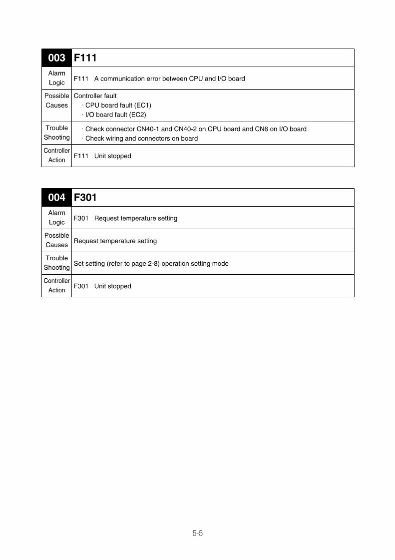
5-5
F111003AlarmLogic
F111 A communication error between CPU and I/O board
Controller fault・CPU board fault (EC1)・I/O board fault (EC2)
・Check connector CN40-1 and CN40-2 on CPU board and CN6 on I/O board・Check wiring and connectors on board
F111 Unit stopped
PossibleCauses
TroubleShooting
ControllerAction
F301004AlarmLogic
F301 Request temperature setting
Request temperature setting
Set setting (refer to page 2-8) operation setting mode
F301 Unit stopped
PossibleCauses
TroubleShooting
ControllerAction
05_01-23_LXE10E100以降_E.qxd 2015.03.06 9:59 ページ 5-5
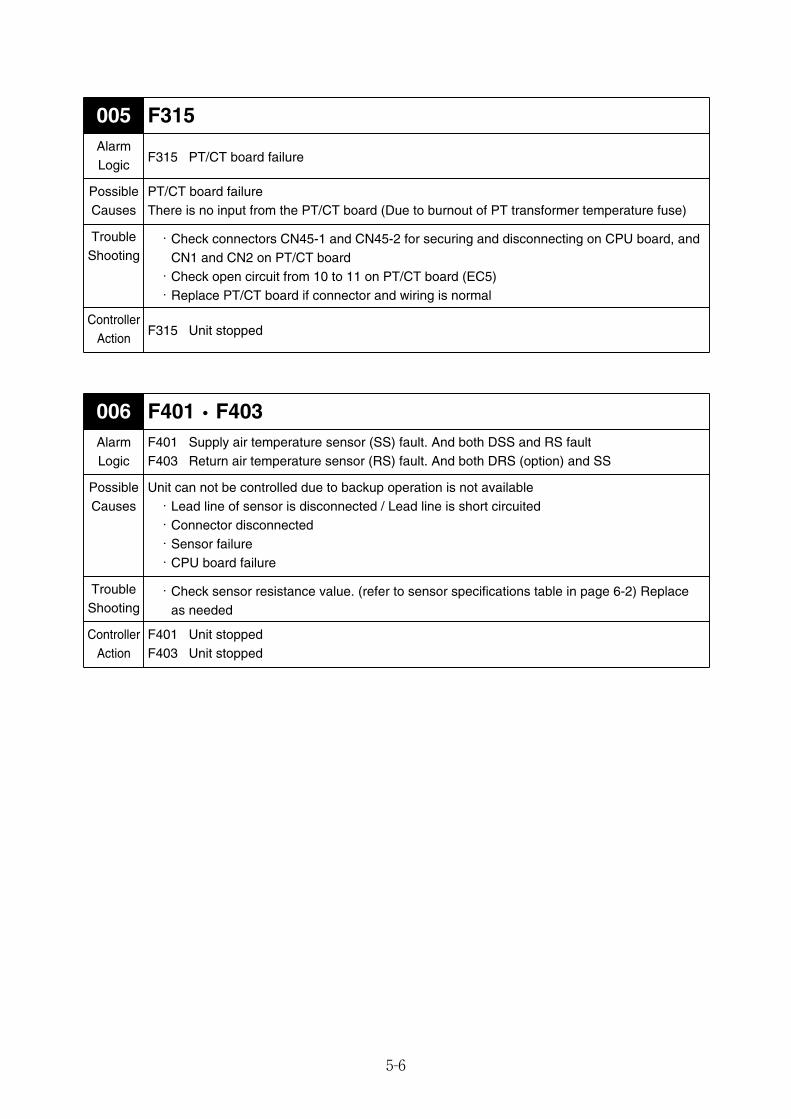
5-6
F401・F403006AlarmLogic
F401 Supply air temperature sensor (SS) fault. And both DSS and RS faultF403 Return air temperature sensor (RS) fault. And both DRS (option) and SS
Unit can not be controlled due to backup operation is not available・Lead line of sensor is disconnected / Lead line is short circuited・Connector disconnected・Sensor failure・CPU board failure
・Check sensor resistance value. (refer to sensor specifications table in page 6-2) Replaceas needed
F401 Unit stoppedF403 Unit stopped
PossibleCauses
TroubleShooting
ControllerAction
F315005AlarmLogic
F315 PT/CT board failure
PT/CT board failureThere is no input from the PT/CT board (Due to burnout of PT transformer temperature fuse)
・Check connectors CN45-1 and CN45-2 for securing and disconnecting on CPU board, andCN1 and CN2 on PT/CT board・Check open circuit from 10 to 11 on PT/CT board (EC5)・Replace PT/CT board if connector and wiring is normal
F315 Unit stopped
PossibleCauses
TroubleShooting
ControllerAction
05_01-23_LXE10E100以降_E.qxd 2015.03.06 9:59 ページ 5-6
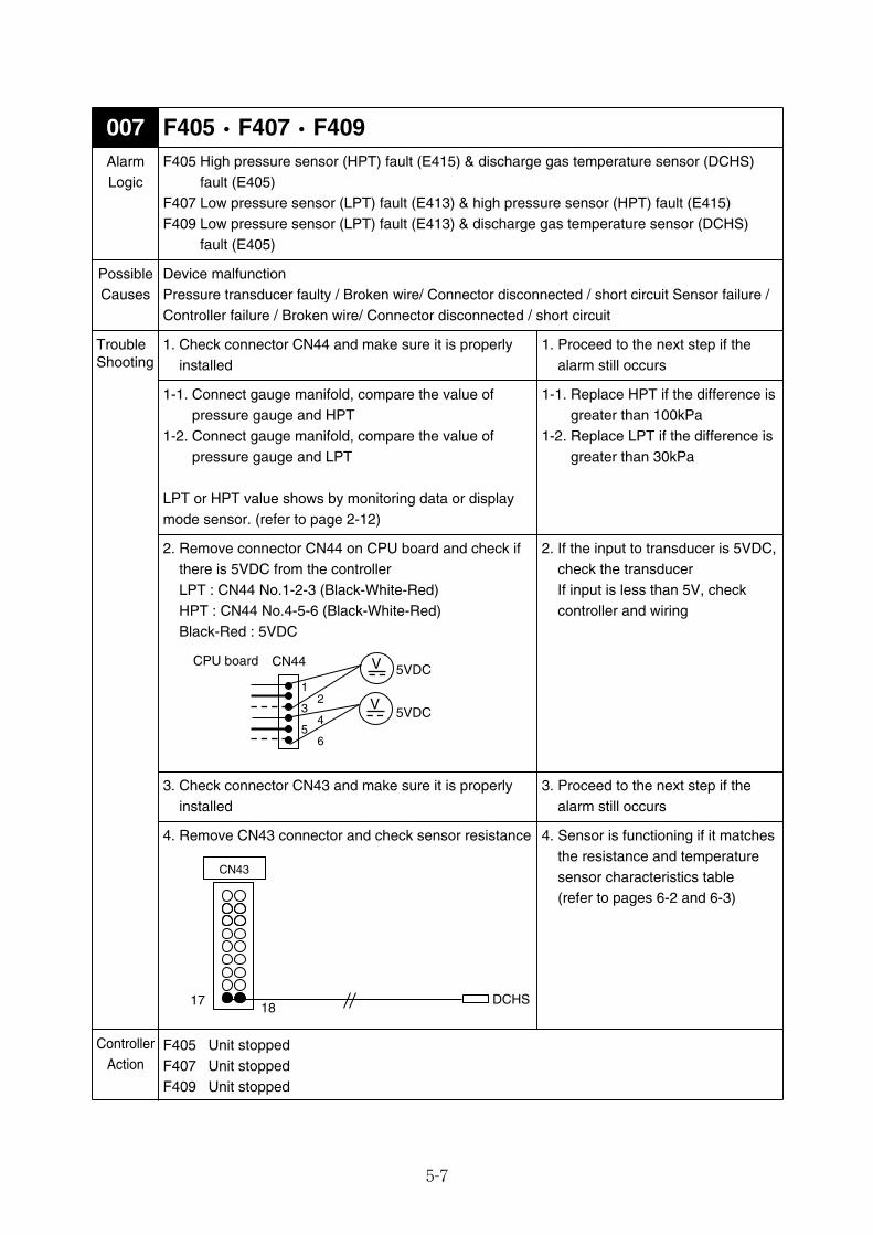
5-7
F405・F407・F409007AlarmLogic
F405 High pressure sensor (HPT) fault (E415) & discharge gas temperature sensor (DCHS)fault (E405)
F407 Low pressure sensor (LPT) fault (E413) & high pressure sensor (HPT) fault (E415)F409 Low pressure sensor (LPT) fault (E413) & discharge gas temperature sensor (DCHS)
fault (E405)
Device malfunctionPressure transducer faulty / Broken wire/ Connector disconnected / short circuit Sensor failure /Controller failure / Broken wire/ Connector disconnected / short circuit
1. Check connector CN44 and make sure it is properlyinstalled
F405 Unit stoppedF407 Unit stoppedF409 Unit stopped
PossibleCauses
TroubleShooting
ControllerAction
1-1. Connect gauge manifold, compare the value ofpressure gauge and HPT
1-2. Connect gauge manifold, compare the value ofpressure gauge and LPT
LPT or HPT value shows by monitoring data or displaymode sensor. (refer to page 2-12)
2. Remove connector CN44 on CPU board and check ifthere is 5VDC from the controllerLPT : CN44 No.1-2-3 (Black-White-Red)HPT : CN44 No.4-5-6 (Black-White-Red)Black-Red : 5VDC
1. Proceed to the next step if thealarm still occurs
1-1. Replace HPT if the difference isgreater than 100kPa
1-2. Replace LPT if the difference isgreater than 30kPa
2. If the input to transducer is 5VDC,check the transducerIf input is less than 5V, checkcontroller and wiring
V
V
CN44CPU board
1
3
5
2
4
6
5VDC
5VDC
3. Check connector CN43 and make sure it is properlyinstalled
3. Proceed to the next step if thealarm still occurs
4. Remove CN43 connector and check sensor resistance 4. Sensor is functioning if it matchesthe resistance and temperaturesensor characteristics table(refer to pages 6-2 and 6-3)
DCHS
CN43
17 18
05_01-23_LXE10E100以降_E.qxd 2015.03.06 9:59 ページ 5-7
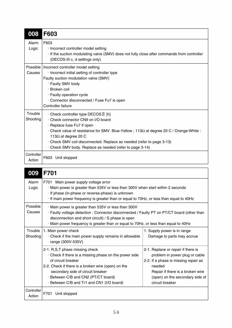
5-8
F603008AlarmLogic
F603・Incorrect controller model setting・If the suction modulating valve (SMV) does not fully close after commands from controller
(DECOS-III c, d settings only)
Incorrect controller model setting・Incorrect initial setting of controller type
Faulty suction modulation valve (SMV)・Faulty SMV body・Broken coil・Faulty operation cycle・Connector disconnected / Fuse Fu7 is open
Controller failure
・Check controller type DECOSⅢ [h]・Check connector CN9 on I/O board・Replace fuse Fu7 if open・Check value of resistance for SMV. Blue-Yellow : 113Ω at degree 20 C / Orange-White :
113Ω at degree 20 C・Check SMV coil disconnected. Replace as needed (refer to page 3-13)・Check SMV body. Replace as needed (refer to page 3-14)
F603 Unit stopped
PossibleCauses
TroubleShooting
ControllerAction
F701009AlarmLogic
F701 Main power supply voltage error・Main power is greater than 535V or less than 300V when start within 2 seconds・If phase (in-phase or reverse-phase) is unknown・If main power frequency is greater than or equal to 70Hz, or less than equal to 40Hz
・Main power is greater than 535V or less than 300V・Faulty voltage detection : Connector disconnected / Faulty PT on PT/CT board (other than
disconnection and short circuit) / S phase is open・Main power frequency is greater than or equal to 70Hz, or less than equal to 40Hz
1. Main power check・Check if the main power supply remains in allowable
range (300V-535V)
2-1. R,S,T phase missing check・Check if there is a missing phase on the power side
of circuit breaker2-2. Check if there is a broken wire (open) on the
secondary side of circuit breaker・Between C/B and CN2 (PT/CT board)・Between C/B and Tr1 and CN1 (I/O board)
F701 Unit stopped
PossibleCauses
TroubleShooting
ControllerAction
1. Supply power is in range Damage to parts may accrue
2-1. Replace or repair if there isproblem in power plug or cable
2-2. If a phase is missing repair asneeded Repair if there is a broken wire(open) on the secondary side ofcircuit breaker
05_01-23_LXE10E100以降_E.qxd 2015.03.06 9:59 ページ 5-8
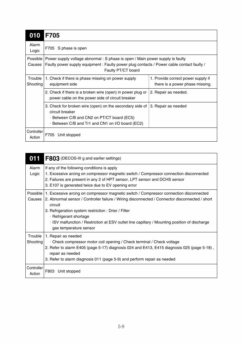
5-9
F705010AlarmLogic
F705 S phase is open
Power supply voltage abnormal : S phase is open / Main power supply is faultyFaulty power supply equipment : Faulty power plug contacts / Power cable contact faulty /
Faulty PT/CT board
1. Check if there is phase missing on power supplyequipment side
2. Check if there is a broken wire (open) in power plug orpower cable on the power side of circuit breaker
3. Check for broken wire (open) on the secondary side ofcircuit breaker・Between C/B and CN2 on PT/CT board (EC5)・Between C/B and Tr1 and CN1 on I/O board (EC2)
F705 Unit stopped
PossibleCauses
TroubleShooting
ControllerAction
1. Provide correct power supply ifthere is a power phase missing.
2. Repair as needed.
3. Repair as needed
F803 (DECOS-III g and earlier settings)011AlarmLogic
If any of the following conditions is apply1. Excessive arcing on compressor magnetic switch / Compressor connection disconnected2. Failures are present in any 2 of HPT sensor, LPT sensor and DCHS sensor3. E107 is generated twice due to EV opening error
1. Excessive arcing on compressor magnetic switch / Compressor connection disconnected2. Abnormal sensor / Controller failure / Wiring disconnected / Connector disconnected / short
circuit3. Refrigeration system restriction : Drier / Filter・Refrigerant shortage・ISV malfunction / Restriction at ESV outlet line capillary / Mounting position of discharge
gas temperature sensor
1. Repair as needed・Check compressor motor coil opening / Check terminal / Check voltage
2. Refer to alarm E405 (page 5-17) diagnosis 024 and E413, E415 diagnosis 025 (page 5-18) ,repair as needed
3. Refer to alarm diagnosis 011 (page 5-9) and perform repair as needed
F803 Unit stopped
PossibleCauses
TroubleShooting
ControllerAction
05_01-23_LXE10E100以降_E.qxd 2015.03.06 9:59 ページ 5-9
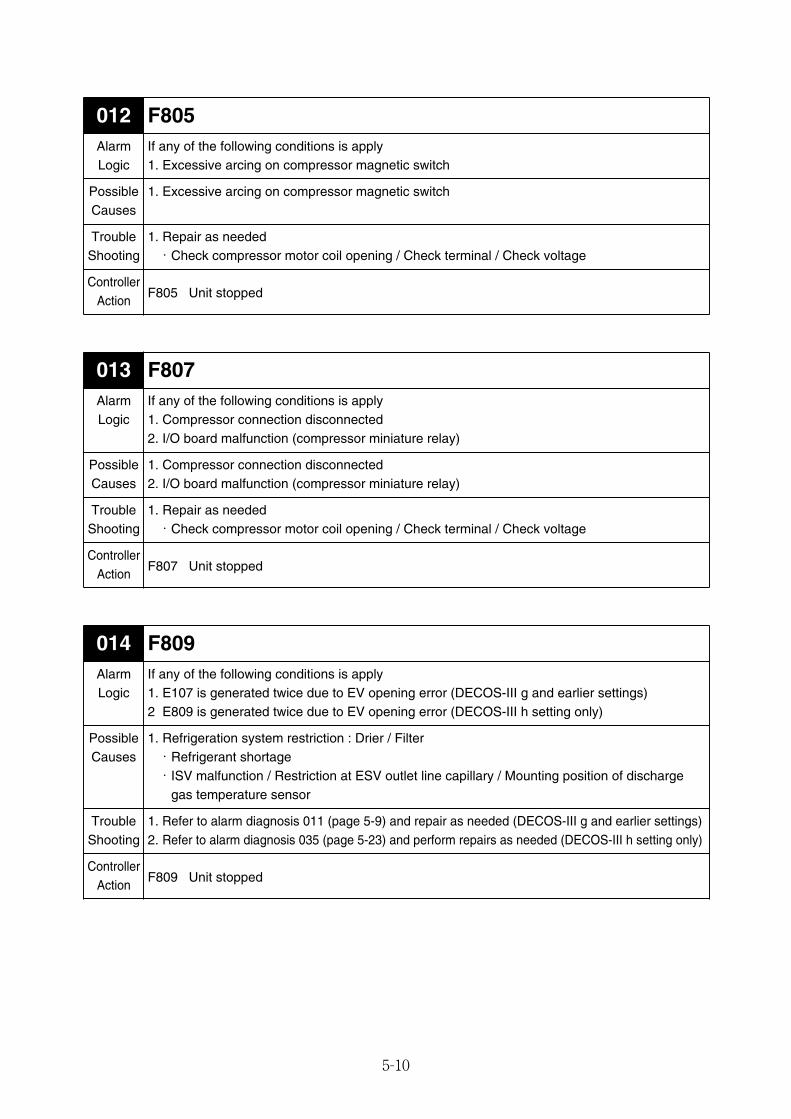
5-10
F805012AlarmLogic
If any of the following conditions is apply1. Excessive arcing on compressor magnetic switch
1. Excessive arcing on compressor magnetic switch
1. Repair as needed・Check compressor motor coil opening / Check terminal / Check voltage
F805 Unit stopped
PossibleCauses
TroubleShooting
ControllerAction
F807013AlarmLogic
If any of the following conditions is apply1. Compressor connection disconnected2. I/O board malfunction (compressor miniature relay)
1. Compressor connection disconnected2. I/O board malfunction (compressor miniature relay)
1. Repair as needed・Check compressor motor coil opening / Check terminal / Check voltage
F807 Unit stopped
PossibleCauses
TroubleShooting
ControllerAction
F809014AlarmLogic
If any of the following conditions is apply1. E107 is generated twice due to EV opening error (DECOS-III g and earlier settings)2 E809 is generated twice due to EV opening error (DECOS-III h setting only)
1. Refrigeration system restriction : Drier / Filter・Refrigerant shortage・ISV malfunction / Restriction at ESV outlet line capillary / Mounting position of discharge
gas temperature sensor
1. Refer to alarm diagnosis 011 (page 5-9) and repair as needed (DECOS-III g and earlier settings)2. Refer to alarm diagnosis 035 (page 5-23) and perform repairs as needed (DECOS-III h setting only)
F809 Unit stopped
PossibleCauses
TroubleShooting
ControllerAction
05_01-23_LXE10E100以降_E.qxd 2015.03.06 9:59 ページ 5-10
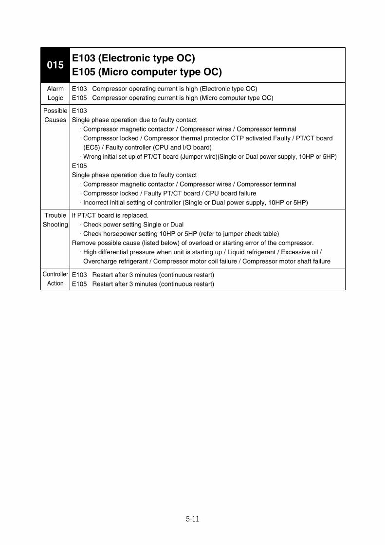
5-11
E103 (Electronic type OC)E105 (Micro computer type OC)
015
AlarmLogic
E103 Compressor operating current is high (Electronic type OC)E105 Compressor operating current is high (Micro computer type OC)
E103Single phase operation due to faulty contact・Compressor magnetic contactor / Compressor wires / Compressor terminal・Compressor locked / Compressor thermal protector CTP activated Faulty / PT/CT board
(EC5) / Faulty controller (CPU and I/O board)・Wrong initial set up of PT/CT board (Jumper wire)(Single or Dual power supply, 10HP or 5HP)
E105Single phase operation due to faulty contact・Compressor magnetic contactor / Compressor wires / Compressor terminal・Compressor locked / Faulty PT/CT board / CPU board failure・Incorrect initial setting of controller (Single or Dual power supply, 10HP or 5HP)
If PT/CT board is replaced.・Check power setting Single or Dual・Check horsepower setting 10HP or 5HP (refer to jumper check table)
Remove possible cause (listed below) of overload or starting error of the compressor.・High differential pressure when unit is starting up / Liquid refrigerant / Excessive oil /
Overcharge refrigerant / Compressor motor coil failure / Compressor motor shaft failure
E103 Restart after 3 minutes (continuous restart)E105 Restart after 3 minutes (continuous restart)
PossibleCauses
TroubleShooting
ControllerAction
05_01-23_LXE10E100以降_E.qxd 2015.03.06 9:59 ページ 5-11
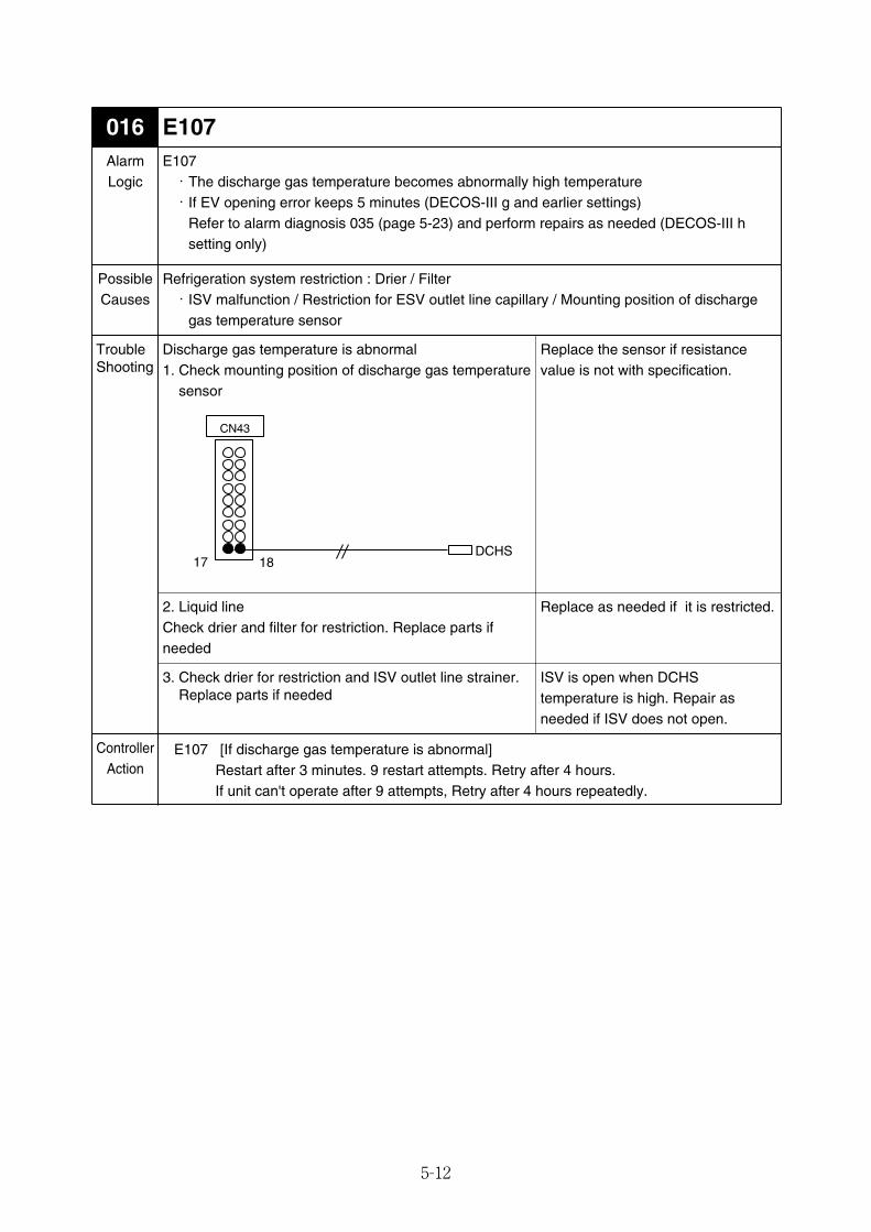
5-12
E107016AlarmLogic
E107・The discharge gas temperature becomes abnormally high temperature・If EV opening error keeps 5 minutes (DECOS-III g and earlier settings)
Refer to alarm diagnosis 035 (page 5-23) and perform repairs as needed (DECOS-III hsetting only)
Refrigeration system restriction : Drier / Filter・ISV malfunction / Restriction for ESV outlet line capillary / Mounting position of discharge
gas temperature sensor
Discharge gas temperature is abnormal1. Check mounting position of discharge gas temperature
sensor
2. Liquid lineCheck drier and filter for restriction. Replace parts ifneeded
3. Check drier for restriction and ISV outlet line strainer.Replace parts if needed
E107 [If discharge gas temperature is abnormal]Restart after 3 minutes. 9 restart attempts. Retry after 4 hours.If unit can't operate after 9 attempts, Retry after 4 hours repeatedly.
PossibleCauses
TroubleShooting
ControllerAction
Replace as needed if it is restricted.
ISV is open when DCHStemperature is high. Repair asneeded if ISV does not open.
DCHS
CN43
17 18
Replace the sensor if resistancevalue is not with specification.
05_01-23_LXE10E100以降_E.qxd 2015.03.06 9:59 ページ 5-12
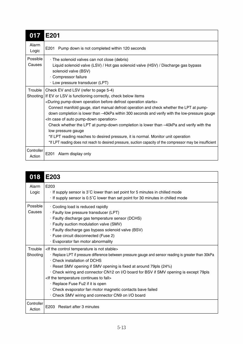
5-13
E201017AlarmLogic
E201 Pump down is not completed within 120 seconds
・The solenoid valves can not close (debris)Liquid solenoid valve (LSV) / Hot gas solenoid valve (HSV) / Discharge gas bypasssolenoid valve (BSV)・Compressor failure・Low pressure transducer (LPT)
Check EV and LSV (refer to page 5-4)If EV or LSV is functioning correctly, check below items<During pump-down operation before defrost operation starts>
Connect manifold gauge, start manual defrost operation and check whether the LPT at pump-down completion is lower than –40kPa within 300 seconds and verify with the low-pressure gauge
<In case of auto pump-down operation>Check whether the LPT at pump-down completion is lower than –40kPa and verify with thelow pressure gauge*If LPT reading reaches to desired pressure, it is normal. Monitor unit operation*If LPT reading does not reach to desired pressure, suction capacity of the compressor may be insufficient
E201 Alarm display only
PossibleCauses
TroubleShooting
ControllerAction
E203018AlarmLogic
E203・If supply sensor is 3˚C lower than set point for 5 minutes in chilled mode・If supply sensor is 0.5˚C lower than set point for 30 minutes in chilled mode
・Cooling load is reduced rapidly・Faulty low pressure transducer (LPT)・Faulty discharge gas temperature sensor (DCHS)・Faulty suction modulation valve (SMV)・Faulty discharge gas bypass solenoid valve (BSV)・Fuse circuit disconnected (Fuse 2)・Evaporator fan motor abnormality
<If the control temperature is not stable>・Replace LPT if pressure difference between pressure gauge and sensor reading is greater than 30kPa・Check installation of DCHS・Reset SMV opening if SMV opening is fixed at around 79pls (24%)・Check wiring and connector CN12 on I/O board for BSV if SMV opening is except 79pls
<If the temperature continues to fall>・Replace Fuse Fu2 if it is open・Check evaporator fan motor magnetic contacts bave failed・Check SMV wiring and connector CN9 on I/O board
E203 Restart after 3 minutes
PossibleCauses
TroubleShooting
ControllerAction
05_01-23_LXE10E100以降_E.qxd 2015.03.06 9:59 ページ 5-13
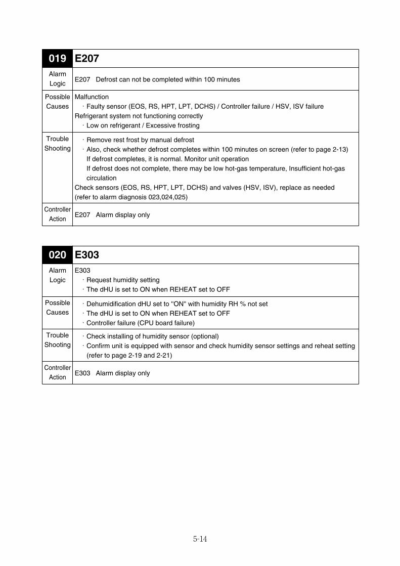
5-14
E207019AlarmLogic
E207 Defrost can not be completed within 100 minutes
Malfunction・Faulty sensor (EOS, RS, HPT, LPT, DCHS) / Controller failure / HSV, ISV failure
Refrigerant system not functioning correctly・Low on refrigerant / Excessive frosting
・Remove rest frost by manual defrost・Also, check whether defrost completes within 100 minutes on screen (refer to page 2-13)
If defrost completes, it is normal. Monitor unit operationIf defrost does not complete, there may be low hot-gas temperature, Insufficient hot-gascirculation
Check sensors (EOS, RS, HPT, LPT, DCHS) and valves (HSV, ISV), replace as needed(refer to alarm diagnosis 023,024,025)
E207 Alarm display only
PossibleCauses
TroubleShooting
ControllerAction
E303020AlarmLogic
E303・Request humidity setting・The dHU is set to ON when REHEAT set to OFF
・Dehumidification dHU set to ''ON'' with humidity RH % not set・The dHU is set to ON when REHEAT set to OFF・Controller failure (CPU board failure)
・Check installing of humidity sensor (optional)・Confirm unit is equipped with sensor and check humidity sensor settings and reheat setting
(refer to page 2-19 and 2-21)
E303 Alarm display only
PossibleCauses
TroubleShooting
ControllerAction
05_01-23_LXE10E100以降_E.qxd 2015.03.06 9:59 ページ 5-14
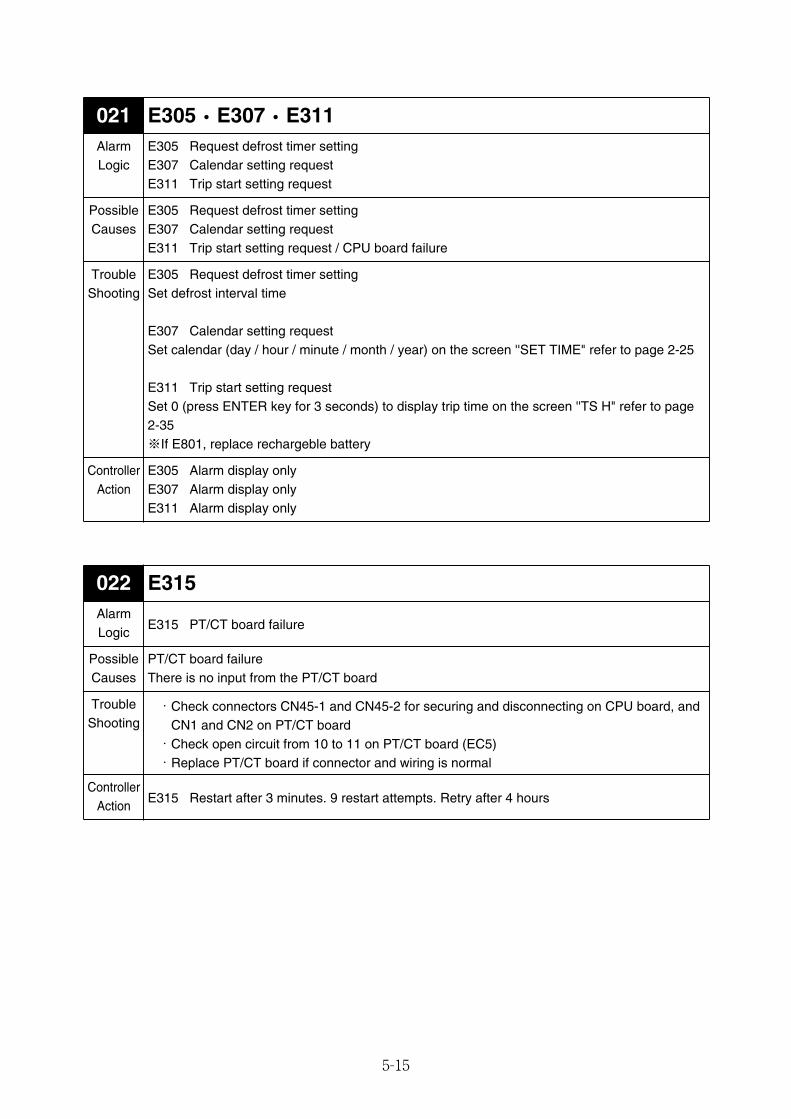
5-15
E305・E307・E311021AlarmLogic
E305 Request defrost timer settingE307 Calendar setting requestE311 Trip start setting request
E305 Alarm display onlyE307 Alarm display onlyE311 Alarm display only
ControllerAction
E315022AlarmLogic
E315 PT/CT board failure
PT/CT board failureThere is no input from the PT/CT board
・Check connectors CN45-1 and CN45-2 for securing and disconnecting on CPU board, andCN1 and CN2 on PT/CT board・Check open circuit from 10 to 11 on PT/CT board (EC5)・Replace PT/CT board if connector and wiring is normal
E315 Restart after 3 minutes. 9 restart attempts. Retry after 4 hours
PossibleCauses
TroubleShooting
ControllerAction
PossibleCauses
E305 Request defrost timer settingE307 Calendar setting requestE311 Trip start setting request / CPU board failure
TroubleShooting
E305 Request defrost timer settingSet defrost interval time
E307 Calendar setting requestSet calendar (day / hour / minute / month / year) on the screen ''SET TIME" refer to page 2-25
E311 Trip start setting requestSet 0 (press ENTER key for 3 seconds) to display trip time on the screen ''TS H" refer to page2-35※If E801, replace rechargeble battery
05_01-23_LXE10E100以降_E.qxd 2015.03.06 9:59 ページ 5-15
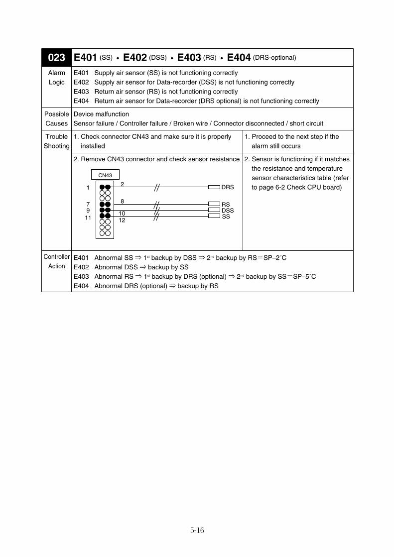
5-16
E401 (SS)・E402 (DSS)・E403 (RS)・E404 (DRS-optional)023AlarmLogic
E401 Supply air sensor (SS) is not functioning correctlyE402 Supply air sensor for Data-recorder (DSS) is not functioning correctlyE403 Return air sensor (RS) is not functioning correctlyE404 Return air sensor for Data-recorder (DRS optional) is not functioning correctly
Device malfunctionSensor failure / Controller failure / Broken wire / Connector disconnected / short circuit
1. Check connector CN43 and make sure it is properlyinstalled
PossibleCauses
TroubleShooting
ControllerAction
E401 Abnormal SS ⇒ 1st backup by DSS ⇒ 2nd backup by RS=SP–2˚CE402 Abnormal DSS ⇒ backup by SSE403 Abnormal RS ⇒ 1st backup by DRS (optional) ⇒ 2nd backup by SS=SP–5˚CE404 Abnormal DRS (optional) ⇒ backup by RS
1. Proceed to the next step if thealarm still occurs
2. Remove CN43 connector and check sensor resistance 2. Sensor is functioning if it matchesthe resistance and temperaturesensor characteristics table (referto page 6-2 Check CPU board)
RS
11 12
7 8
1 2
CN43
9 10
DRS
DSSSS
05_01-23_LXE10E100以降_E.qxd 2015.03.06 9:59 ページ 5-16
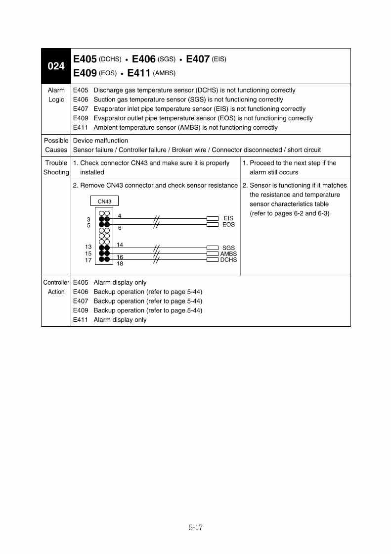
5-17
6
4
15
5
16
3
14
DCHS
13
CN43
17 18
AMBSSGS
EOSEIS
E405 (DCHS)・E406 (SGS)・E407 (EIS)
E409 (EOS)・E411 (AMBS)024
AlarmLogic
E405 Discharge gas temperature sensor (DCHS) is not functioning correctlyE406 Suction gas temperature sensor (SGS) is not functioning correctlyE407 Evaporator inlet pipe temperature sensor (EIS) is not functioning correctlyE409 Evaporator outlet pipe temperature sensor (EOS) is not functioning correctlyE411 Ambient temperature sensor (AMBS) is not functioning correctly
Device malfunctionSensor failure / Controller failure / Broken wire / Connector disconnected / short circuit
1. Check connector CN43 and make sure it is properlyinstalled
PossibleCauses
TroubleShooting
ControllerAction
E405 Alarm display onlyE406 Backup operation (refer to page 5-44)E407 Backup operation (refer to page 5-44)E409 Backup operation (refer to page 5-44)E411 Alarm display only
1. Proceed to the next step if thealarm still occurs
2. Remove CN43 connector and check sensor resistance 2. Sensor is functioning if it matchesthe resistance and temperaturesensor characteristics table(refer to pages 6-2 and 6-3)
05_01-23_LXE10E100以降_E.qxd 2015.03.06 9:59 ページ 5-17
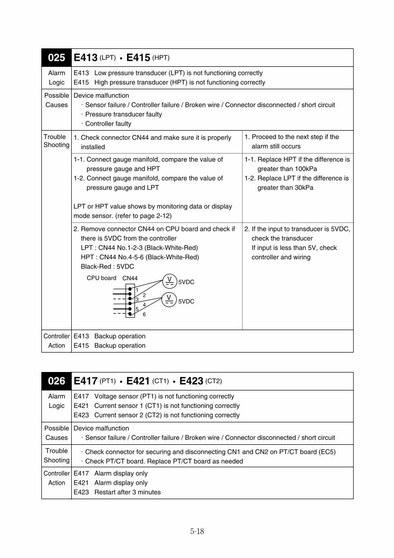
5-18
E417 (PT1)・E421 (CT1)・E423 (CT2)026AlarmLogic
E417 Voltage sensor (PT1) is not functioning correctlyE421 Current sensor 1 (CT1) is not functioning correctlyE423 Current sensor 2 (CT2) is not functioning correctly
Device malfunction・Sensor failure / Controller failure / Broken wire / Connector disconnected / short circuit
・Check connector for securing and disconnecting CN1 and CN2 on PT/CT board (EC5)・Check PT/CT board. Replace PT/CT board as needed
E417 Alarm display onlyE421 Alarm display onlyE423 Restart after 3 minutes
PossibleCauses
TroubleShooting
ControllerAction
E413 (LPT)・E415 (HPT)025AlarmLogic
E413 Low pressure transducer (LPT) is not functioning correctlyE415 High pressure transducer (HPT) is not functioning correctly
Device malfunction・Sensor failure / Controller failure / Broken wire / Connector disconnected / short circuit・Pressure transducer faulty・Controller faulty
1. Check connector CN44 and make sure it is properlyinstalled
1-1. Connect gauge manifold, compare the value ofpressure gauge and HPT
1-2. Connect gauge manifold, compare the value ofpressure gauge and LPT
LPT or HPT value shows by monitoring data or displaymode sensor. (refer to page 2-12)
2. Remove connector CN44 on CPU board and check ifthere is 5VDC from the controllerLPT : CN44 No.1-2-3 (Black-White-Red)HPT : CN44 No.4-5-6 (Black-White-Red)Black-Red : 5VDC
PossibleCauses
TroubleShooting
ControllerAction
E413 Backup operationE415 Backup operation
1. Proceed to the next step if thealarm still occurs
1-1. Replace HPT if the difference isgreater than 100kPa
1-2. Replace LPT if the difference isgreater than 30kPa
2. If the input to transducer is 5VDC,check the transducerIf input is less than 5V, checkcontroller and wiring
V
V
CN44CPU board
1
3
5
2
4
6
5VDC
5VDC
05_01-23_LXE10E100以降_E.qxd 2015.03.06 9:59 ページ 5-18
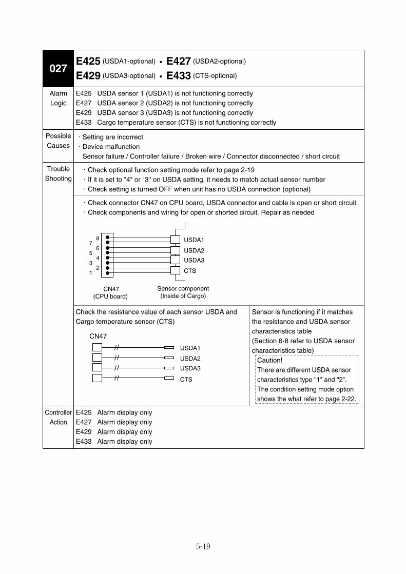
5-19
E425 (USDA1-optional)・E427 (USDA2-optional)
E429 (USDA3-optional)・E433 (CTS-optional)027
AlarmLogic
E425 USDA sensor 1 (USDA1) is not functioning correctlyE427 USDA sensor 2 (USDA2) is not functioning correctlyE429 USDA sensor 3 (USDA3) is not functioning correctlyE433 Cargo temperature sensor (CTS) is not functioning correctly
・Setting are incorrect・Device malfunction
Sensor failure / Controller failure / Broken wire / Connector disconnected / short circuit
・Check optional function setting mode refer to page 2-19・If it is set to "4" or "3'' on USDA setting, it needs to match actual sensor number・Check setting is turned OFF when unit has no USDA connection (optional)
・Check connector CN47 on CPU board, USDA connector and cable is open or short circuit・Check components and wiring for open or shorted circuit. Repair as needed
Check the resistance value of each sensor USDA andCargo temperature sensor (CTS)
E425 Alarm display onlyE427 Alarm display onlyE429 Alarm display onlyE433 Alarm display only
PossibleCauses
ControllerAction
USDA1
USDA2
USDA3
CTS
CN47 (CPU board)
Sensor component (Inside of Cargo)
7
5
3
1
8
6
4
2
USDA1
USDA2
USDA3
CTS
CN47
Sensor is functioning if it matchesthe resistance and USDA sensorcharacteristics table(Section 6-8 refer to USDA sensorcharacteristics table)
Caution!There are different USDA sensorcharacteristics type ''1" and ''2".The condition setting mode optionshows the what refer to page 2-22.
TroubleShooting
05_01-23_LXE10E100以降_E.qxd 2015.03.06 9:59 ページ 5-19
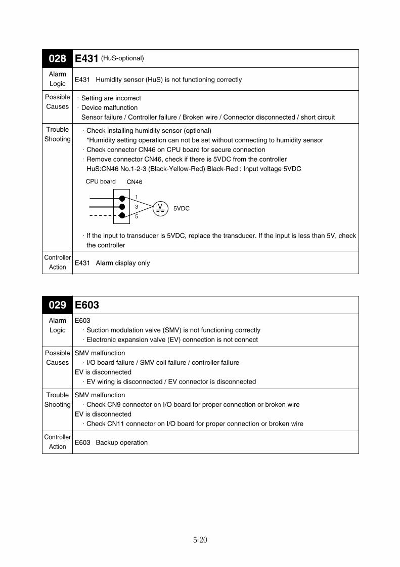
5-20
E603029AlarmLogic
E603・Suction modulation valve (SMV) is not functioning correctly・Electronic expansion valve (EV) connection is not connect
SMV malfunction・I/O board failure / SMV coil failure / controller failure
EV is disconnected・EV wiring is disconnected / EV connector is disconnected
SMV malfunction・Check CN9 connector on I/O board for proper connection or broken wire
EV is disconnected・Check CN11 connector on I/O board for proper connection or broken wire
E603 Backup operation
PossibleCauses
TroubleShooting
ControllerAction
E431 (HuS-optional)028AlarmLogic
E431 Humidity sensor (HuS) is not functioning correctly
・Setting are incorrect・Device malfunction
Sensor failure / Controller failure / Broken wire / Connector disconnected / short circuit
・Check installing humidity sensor (optional)*Humidity setting operation can not be set without connecting to humidity sensor・Check connector CN46 on CPU board for secure connection・Remove connector CN46, check if there is 5VDC from the controller
HuS:CN46 No.1-2-3 (Black-Yellow-Red) Black-Red : Input voltage 5VDC
・If the input to transducer is 5VDC, replace the transducer. If the input is less than 5V, checkthe controller
E431 Alarm display only
PossibleCauses
TroubleShooting
ControllerAction
CN46CPU board
V
1
3
55VDC
05_01-23_LXE10E100以降_E.qxd 2015.03.06 9:59 ページ 5-20
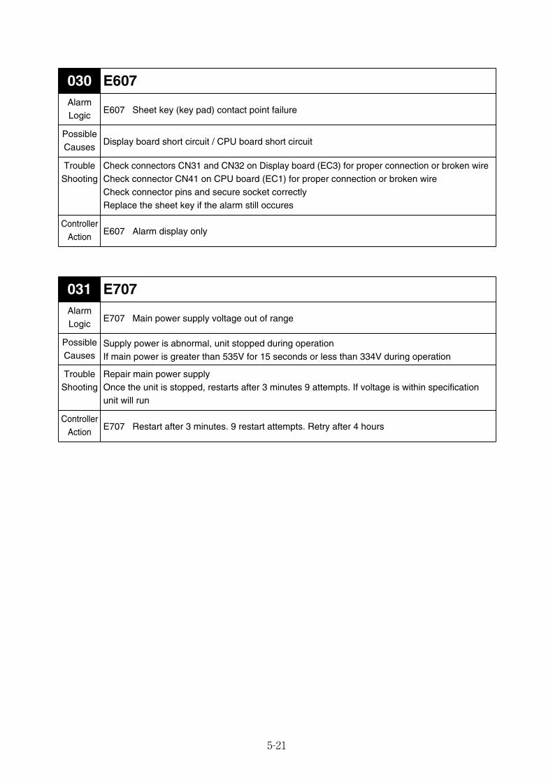
5-21
E607030AlarmLogic
E607 Sheet key (key pad) contact point failure
Display board short circuit / CPU board short circuit
Check connectors CN31 and CN32 on Display board (EC3) for proper connection or broken wireCheck connector CN41 on CPU board (EC1) for proper connection or broken wireCheck connector pins and secure socket correctlyReplace the sheet key if the alarm still occures
E607 Alarm display only
PossibleCauses
TroubleShooting
ControllerAction
E707031AlarmLogic
E707 Main power supply voltage out of range
Supply power is abnormal, unit stopped during operationIf main power is greater than 535V for 15 seconds or less than 334V during operation
Repair main power supplyOnce the unit is stopped, restarts after 3 minutes 9 attempts. If voltage is within specificationunit will run
E707 Restart after 3 minutes. 9 restart attempts. Retry after 4 hours
PossibleCauses
TroubleShooting
ControllerAction
05_01-23_LXE10E100以降_E.qxd 2015.03.06 9:59 ページ 5-21
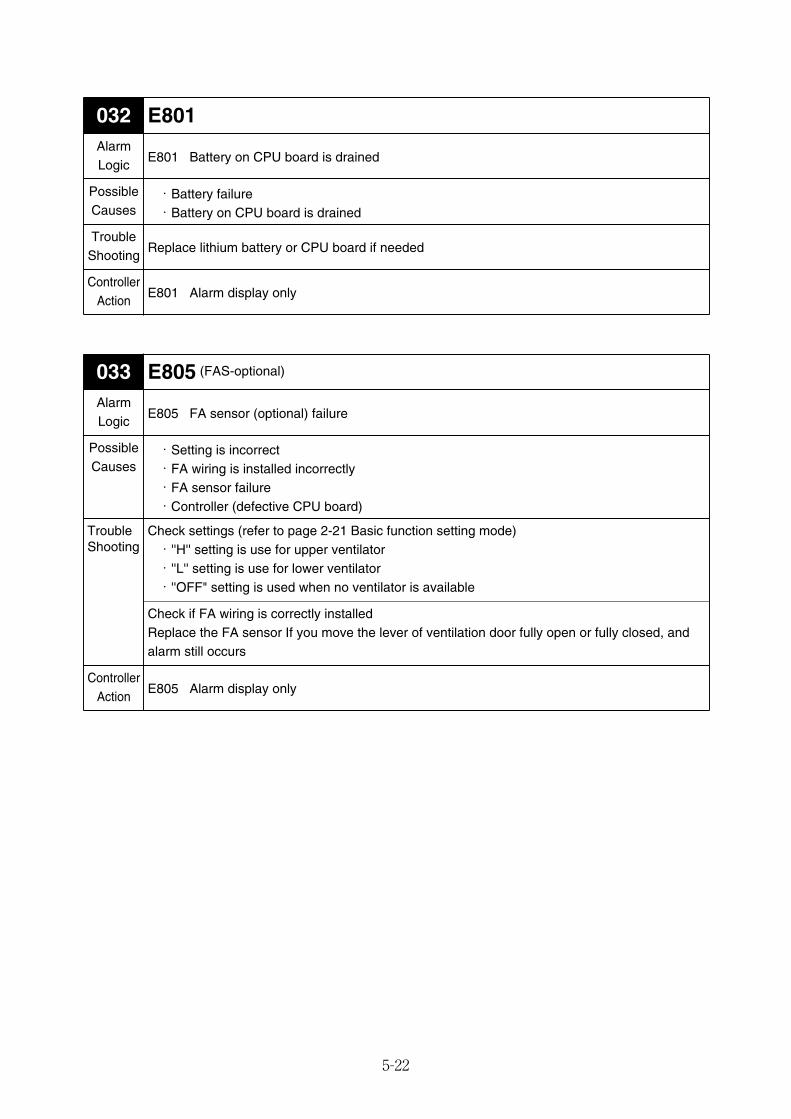
5-22
E801032AlarmLogic
E801 Battery on CPU board is drained
・Battery failure・Battery on CPU board is drained
Replace lithium battery or CPU board if needed
E801 Alarm display only
PossibleCauses
TroubleShooting
ControllerAction
E805 (FAS-optional)033AlarmLogic
E805 FA sensor (optional) failure
・Setting is incorrect・FA wiring is installed incorrectly・FA sensor failure・Controller (defective CPU board)
Check settings (refer to page 2-21 Basic function setting mode)・''H'' setting is use for upper ventilator・''L'' setting is use for lower ventilator・''OFF" setting is used when no ventilator is available
Check if FA wiring is correctly installedReplace the FA sensor If you move the lever of ventilation door fully open or fully closed, andalarm still occurs
E805 Alarm display only
PossibleCauses
TroubleShooting
ControllerAction
05_01-23_LXE10E100以降_E.qxd 2015.03.06 9:59 ページ 5-22
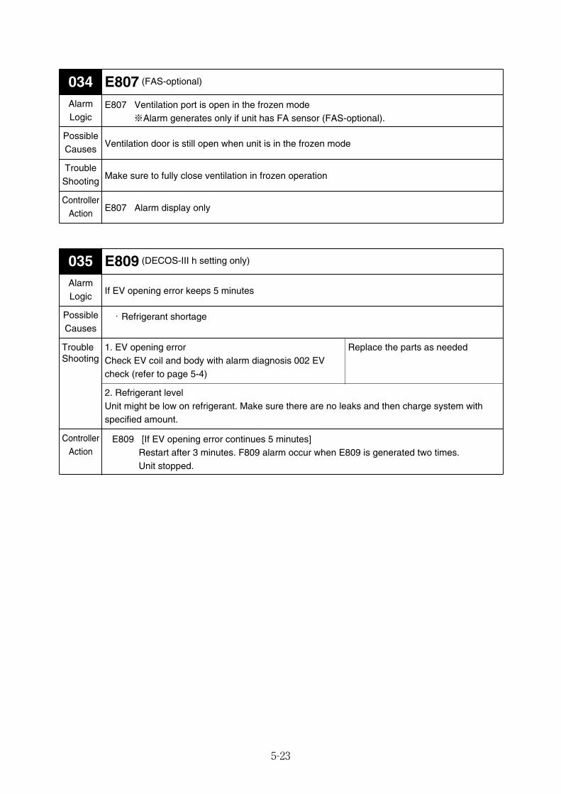
5-23
E807 (FAS-optional)034AlarmLogic
E807 Ventilation port is open in the frozen mode※Alarm generates only if unit has FA sensor (FAS-optional).
Ventilation door is still open when unit is in the frozen mode
Make sure to fully close ventilation in frozen operation
E807 Alarm display only
PossibleCauses
TroubleShooting
ControllerAction
E809 (DECOS-III h setting only)035AlarmLogic
If EV opening error keeps 5 minutes
・Refrigerant shortage
2. Refrigerant levelUnit might be low on refrigerant. Make sure there are no leaks and then charge system withspecified amount.
E809 [If EV opening error continues 5 minutes]Restart after 3 minutes. F809 alarm occur when E809 is generated two times.Unit stopped.
PossibleCauses
ControllerAction
1. EV opening errorCheck EV coil and body with alarm diagnosis 002 EVcheck (refer to page 5-4)
Replace the parts as neededTroubleShooting
05_01-23_LXE10E100以降_E.qxd 2015.03.06 9:59 ページ 5-23
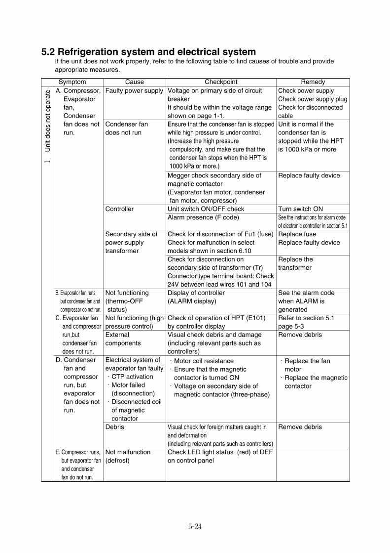
5-24
5.2 Refrigeration system and electrical systemIf the unit does not work properly, refer to the following table to find causes of trouble and provideappropriate measures.
Symptom Checkpoint RemedyCause
D. Condenserfan andcompressorrun, butevaporatorfan does notrun.
Electrical system ofevaporator fan faulty・CTP activation・Motor failed
(disconnection)・Disconnected coil
of magneticcontactor
Debris
E. Compressor runs,but evaporator fanand condenserfan do not run.
Not malfunction(defrost)
・Motor coil resistance・Ensure that the magnetic
contactor is turned ON・Voltage on secondary side of
magnetic contactor (three-phase)
Visual check for foreign matters caught inand deformation(including relevant parts such as controllers)Check LED light status (red) of DEFon control panel
A. Compressor,Evaporatorfan,Condenserfan does notrun.
Faulty power supply
Condenser fandoes not run
Controller
B. Evaporator fan runs,but condenser fan andcompressor do not run.
Not functioning (thermo-OFFstatus)
C. Evaporator fanand compressorrun,butcondenser fandoes not run.
Not functioning (highpressure control)Externalcomponents
Check power supplyCheck power supply plugCheck for disconnectedcableUnit is normal if thecondenser fan isstopped while the HPTis 1000 kPa or more
Replace faulty device
Turn switch ONSee the instructions for alarm codeof electronic controller in section 5.1Replace fuseReplace faulty device
Replace thetransformer
See the alarm codewhen ALARM isgeneratedRefer to section 5.1page 5-3Remove debris
・Replace the fanmotor・Replace the magnetic
contactor
Remove debris
Voltage on primary side of circuitbreakerIt should be within the voltage rangeshown on page 1-1.Ensure that the condenser fan is stoppedwhile high pressure is under control.(Increase the high pressurecompulsorily, and make sure that thecondenser fan stops when the HPT is1000 kPa or more.)
Megger check secondary side ofmagnetic contactor(Evaporator fan motor, condenserfan motor, compressor)
Unit switch ON/OFF checkAlarm presence (F code)
Check for disconnection of Fu1 (fuse)Check for malfunction in selectmodels shown in section 6.10Check for disconnection onsecondary side of transformer (Tr)Connector type terminal board: Check24V between lead wires 101 and 104Display of controller (ALARM display)
Check of operation of HPT (E101) by controller displayVisual check debris and damage(including relevant parts such ascontrollers)
Secondary side ofpower supplytransformer
Ⅰ
Uni
t doe
s no
t ope
rate
05_24-46_LXE10E100以降_E.qxd 15.3.4 11:41 AM ページ 5-24
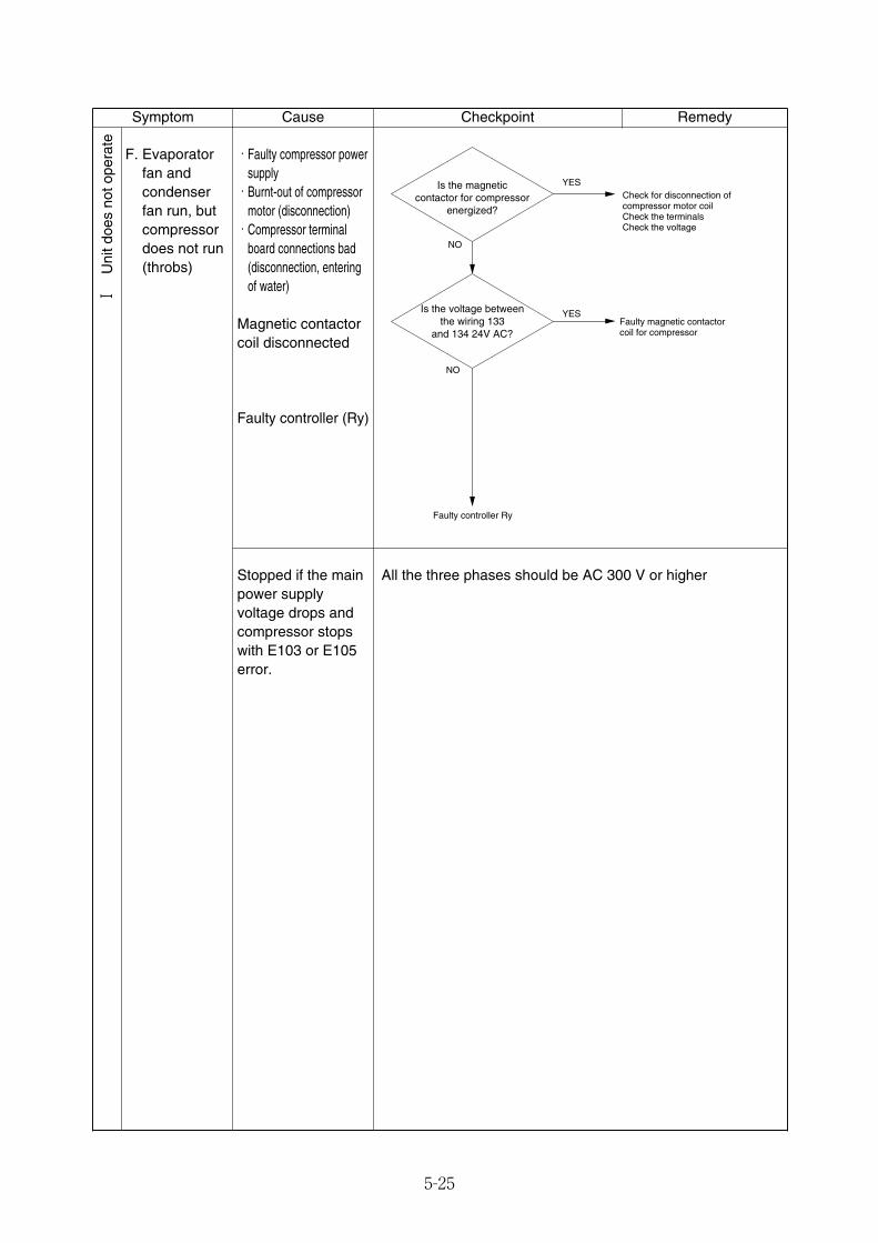
5-25
Symptom Checkpoint RemedyCause
F. Evaporatorfan andcondenserfan run, butcompressordoes not run(throbs)
・Faulty compressor powersupply・Burnt-out of compressor
motor (disconnection)・Compressor terminal
board connections bad(disconnection, enteringof water)
Magnetic contactorcoil disconnected
Faulty controller (Ry)
Is the magneticcontactor for compressor
energized?
Is the voltage betweenthe wiring 133
and 134 24V AC?
Check for disconnection ofcompressor motor coilCheck the terminalsCheck the voltage
Faulty magnetic contactor coil for compressor
Faulty controller Ry
YES
YES
NO
NO
Stopped if the mainpower supplyvoltage drops andcompressor stopswith E103 or E105error.
All the three phases should be AC 300 V or higher
Ⅰ
Uni
t doe
s no
t ope
rate
05_24-46_LXE10E100以降_E.qxd 15.3.4 11:41 AM ページ 5-25
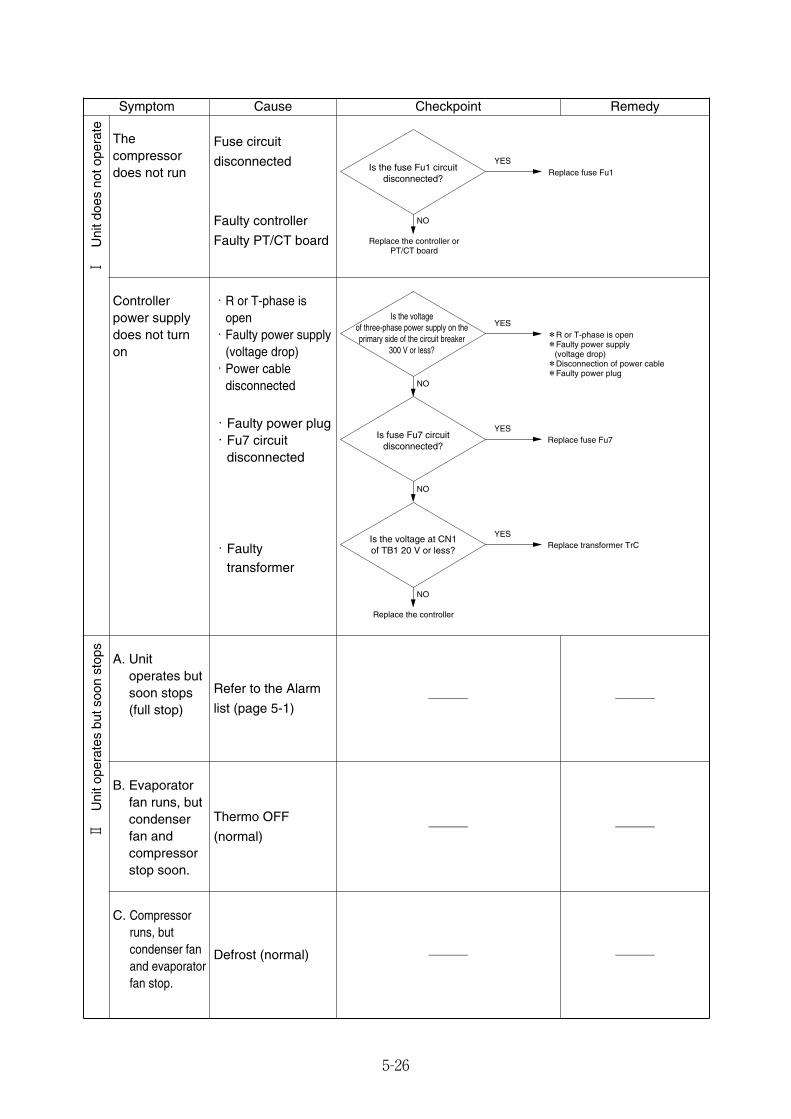
5-26
Symptom Checkpoint RemedyCause
Controllerpower supplydoes not turnon
・R or T-phase isopen・Faulty power supply
(voltage drop)・Power cable
disconnected
・Faulty power plug・Fu7 circuit
disconnected
・Faultytransformer
Is fuse Fu7 circuit disconnected?
Is the voltage at CN1of TB1 20 V or less?
*R or T-phase is open*Faulty power supply (voltage drop)*Disconnection of power cable*Faulty power plug
Replace fuse Fu7
NO
Replace transformer TrC
Replace the controller
Is the voltageof three-phase power supply on theprimary side of the circuit breaker
300 V or less?
NO
NO
YES
YES
YES
Defrost (normal)
Thecompressordoes not run
Fuse circuit
disconnected
Faulty controller
Faulty PT/CT board
Is the fuse Fu1 circuit disconnected?
Replace fuse Fu1
NO
Replace the controller or PT/CT board
YES
A. Unitoperates butsoon stops (full stop)
Refer to the Alarm
list (page 5-1)─── ───
B. Evaporatorfan runs, butcondenserfan andcompressorstop soon.
Thermo OFF
(normal)─── ───
C. Compressorruns, butcondenser fanand evaporatorfan stop.
─── ───
Ⅰ
Uni
t doe
s no
t ope
rate
Ⅱ
Uni
t ope
rate
s bu
t soo
n st
ops
05_24-46_LXE10E100以降_E.qxd 15.3.4 11:41 AM ページ 5-26
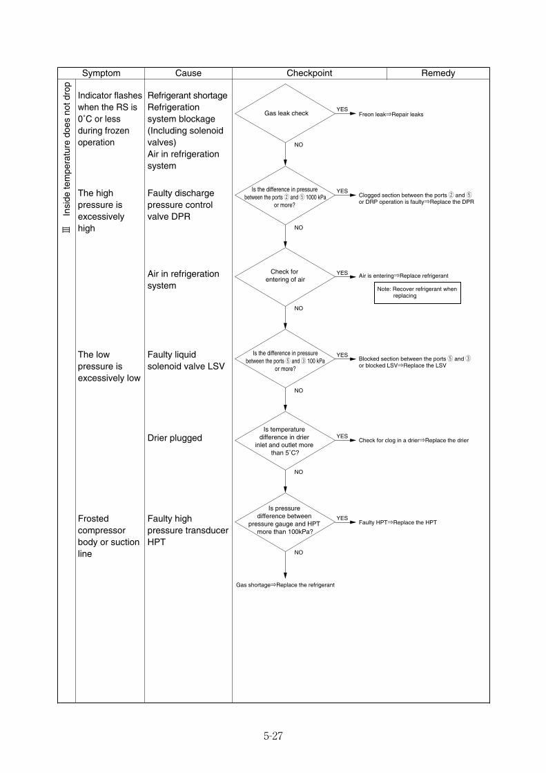
5-27
Symptom Checkpoint RemedyCause
Indicator flasheswhen the RS is0˚C or lessduring frozenoperation
Refrigerant shortageRefrigerationsystem blockage(Including solenoidvalves)Air in refrigerationsystem
The highpressure isexcessivelyhigh
Faulty dischargepressure controlvalve DPR
Air in refrigerationsystem
Faulty liquidsolenoid valve LSV
Drier plugged
Frostedcompressorbody or suctionline
Faulty highpressure transducerHPT
Gas leak check Freon leak⇒Repair leaks
NO
Is the difference in pressure between the ports w and t 1000 kPa
or more?
Clogged section between the ports w and tor DRP operation is faulty⇒Replace the DPR
NO
Is the difference in pressurebetween the ports t and e 100 kPa
or more?
Blocked section between the ports t and eor blocked LSV⇒Replace the LSV
NO
Is temperature difference in drier
inlet and outlet more than 5˚C?
Check for clog in a drier⇒Replace the drier
NO
Check for entering of air
Air is entering⇒Replace refrigerant
NO
Is pressure difference between
pressure gauge and HPT more than 100kPa?
Faulty HPT⇒Replace the HPT
NO
Gas shortage⇒Replace the refrigerant
Note: Recover refrigerant when replacing
YES
YES
YES
YES
YES
YES
Ⅲ
Insi
de te
mpe
ratu
re d
oes
not d
rop
The lowpressure isexcessively low
05_24-46_LXE10E100以降_E.qxd 15.3.4 11:41 AM ページ 5-27
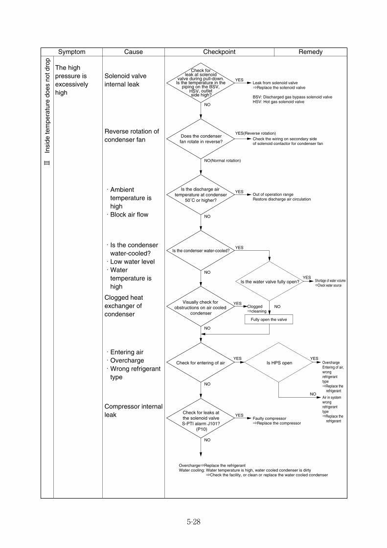
5-28
Symptom Checkpoint RemedyCause
Compressor internalleak
The highpressure isexcessivelyhigh
Solenoid valveinternal leak
Reverse rotation ofcondenser fan
・Ambienttemperature ishigh・Block air flow
・Is the condenserwater-cooled?・Low water level・Water
temperature ishigh
Clogged heatexchanger ofcondenser
・Entering air・Overcharge・Wrong refrigerant
type
Check for leak at solenoid
valve during pull-down. Is the temperature in the
piping on the BSV, HSV, outlet side high?
Does the condenserfan rotate in reverse?
Leak from solenoid valve⇒Replace the solenoid valve
BSV: Discharged gas bypass solenoid valveHSV: Hot gas solenoid valve
Check the wiring on secondary sideof solenoid contactor for condenser fan
Is the discharge air temperature at condenser
50˚C or higher?Out of operation rangeRestore discharge air circulation
Is the condenser water-cooled?
Visually check for obstructions on air cooled
condenser
Clogged⇒cleaning
Check for entering of air
Air in systemwrongrefrigeranttype⇒Replace the refrigerant
OverchargeEntering of air,wrongrefrigeranttype⇒Replace the refrigerant
Check for leaks atthe solenoid valveS-PTI alarm J101?
(P10)
Faulty compressor⇒Replace the compressor
Overcharge⇒Replace the refrigerantWater cooling: Water temperature is high, water cooled condenser is dirty ⇒Check the facility, or clean or replace the water cooled condenser
Is the water valve fully open?YES
Shortage of water volume⇒Check water source
Is HPS openYES
NO
NO
Fully open the valve
YES
NO
YES(Reverse rotation)
NO(Normal rotation)
YES
NO
YES
NO
YES
NO
YES
NO
YES
NO
Ⅲ
Insi
de te
mpe
ratu
re d
oes
not d
rop
05_24-46_LXE10E100以降_E.qxd 15.3.4 11:41 AM ページ 5-28
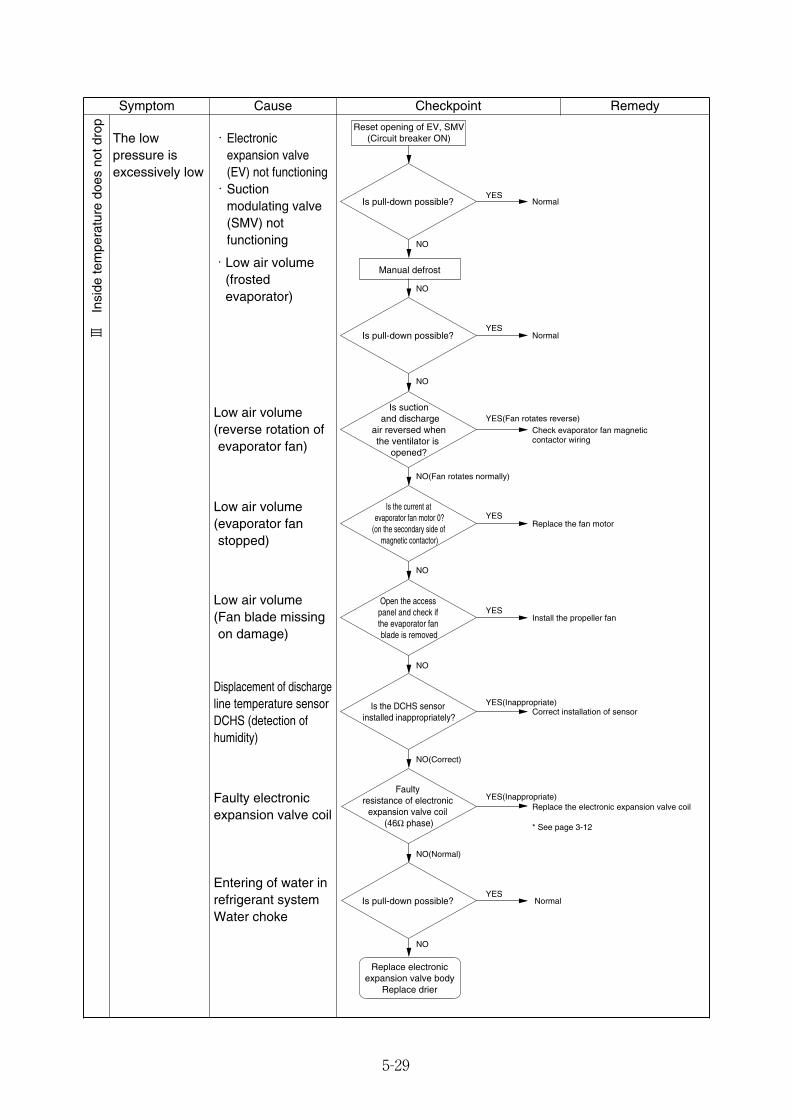
5-29
Symptom Checkpoint RemedyCause
The lowpressure isexcessively low
・Electronicexpansion valve(EV) not functioning・Suction
modulating valve(SMV) notfunctioning
・Low air volume(frostedevaporator)
Low air volume (reverse rotation ofevaporator fan)
Low air volume (evaporator fanstopped)
Low air volume (Fan blade missingon damage)
Displacement of dischargeline temperature sensorDCHS (detection ofhumidity)
Faulty electronicexpansion valve coil
Entering of water inrefrigerant systemWater choke
Ⅲ
Insi
de te
mpe
ratu
re d
oes
not d
rop
NO
Normal
Normal
Normal
NO
Is suction and discharge
air reversed when the ventilator is
opened?
Is the DCHS sensor installed inappropriately?
Faulty resistance of electronic
expansion valve coil (46Ω phase)
YES(Inappropriate)
NO(Correct)
Correct installation of sensor
YES(Inappropriate)Replace the electronic expansion valve coil
Reset opening of EV, SMV(Circuit breaker ON)
Is pull-down possible?
Is pull-down possible?
NO(Fan rotates normally)
Check evaporator fan magnetic contactor wiring
YES(Fan rotates reverse)
Is the current at evaporator fan motor 0?
(on the secondary side of magnetic contactor)
Replace the fan motor
Install the propeller fan
Is pull-down possible?
NO(Normal)
NO
YES
Open the access panel and check if the evaporator fan blade is removed
YES
YES
YES
YES
Manual defrost
NO
NO
NO
Replace electronic expansion valve body
Replace drier
* See page 3-12
05_24-46_LXE10E100以降_E.qxd 15.3.4 11:41 AM ページ 5-29

5-30
Symptom Checkpoint RemedyCause
Suctionpressure is high
Solenoid valveinternal leak(BSV,HSV)
Solenoid valveinternal leak(ISV)
Pressures atcompressor are notcorrect
Replace the compressor
Leak from solenoid valve⇒Replace
Is pull-down possible? Finish
Normal operation
Is HSV, BSV outlet line hot?
Is the ISV outlet line hot?
Circuit breaker OFF→ON
Leak from solenoid valve⇒Replace
*HSV: Hot gas solenoid valveBSV: Discharge gas bypass solenoid valve
*ISV: Injection solenoid valve
YES (Hot)
YES (Hot)
YES
NO (Cold)
NO (Cold)
NO
Ⅲ
Insi
de te
mpe
ratu
re d
oes
not d
rop
05_24-46_LXE10E100以降_E.qxd 15.3.4 11:41 AM ページ 5-30
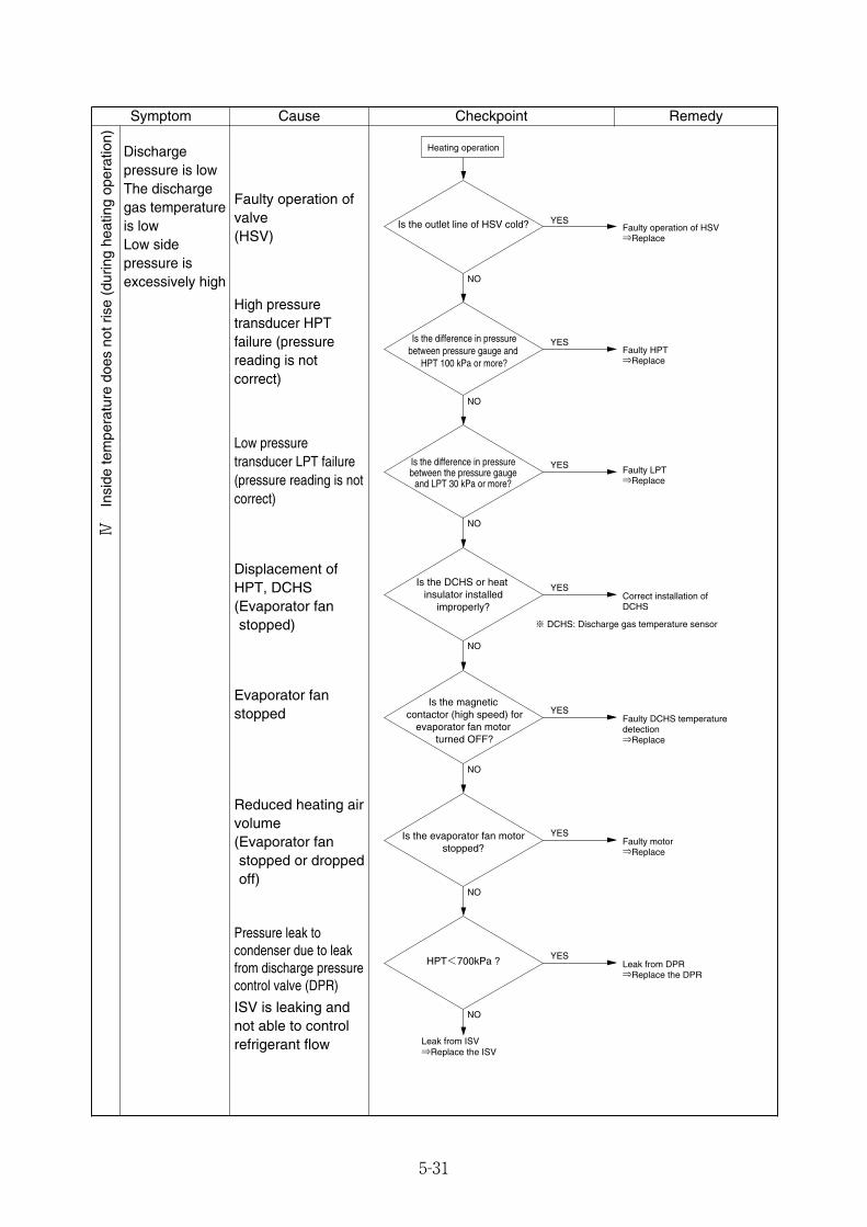
5-31
Symptom Checkpoint RemedyCauseⅣ
Insi
de te
mpe
ratu
re d
oes
not r
ise
(dur
ing
heat
ing
oper
atio
n)
Dischargepressure is lowThe dischargegas temperatureis lowLow sidepressure isexcessively high
YES
YES
Is the outlet line of HSV cold?
Is the difference in pressure between pressure gauge and
HPT 100 kPa or more?
Is the difference in pressure between the pressure gauge
and LPT 30 kPa or more?
Is the DCHS or heat insulator installed
improperly?
Faulty operation of HSV⇒Replace
Faulty HPT⇒Replace
NO
NO
YES Faulty LPT⇒Replace
NO
NO
Is the magnetic contactor (high speed) for
evaporator fan motor turned OFF?
Is the evaporator fan motor stopped?
YESFaulty motor⇒Replace
YESFaulty DCHS temperature detection⇒Replace
YESCorrect installation of DCHS
NO
NO
NO
HPT<700kPa ? YESLeak from DPR⇒Replace the DPR
Leak from ISV⇒Replace the ISV
Heating operation
※ DCHS: Discharge gas temperature sensor
Faulty operation ofvalve (HSV)
High pressuretransducer HPTfailure (pressurereading is notcorrect)
ISV is leaking andnot able to controlrefrigerant flow
Low pressuretransducer LPT failure(pressure reading is notcorrect)
Displacement ofHPT, DCHS(Evaporator fanstopped)
Evaporator fanstopped
Reduced heating airvolume(Evaporator fanstopped or droppedoff)
Pressure leak tocondenser due to leakfrom discharge pressurecontrol valve (DPR)
05_24-46_LXE10E100以降_E.qxd 15.3.4 11:41 AM ページ 5-31
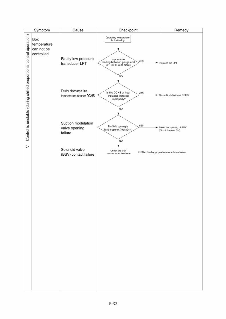
5-32
Symptom Checkpoint RemedyCause
Boxtemperaturecan not becontrolled
Faulty low pressuretransducer LPT
Solenoid valve(BSV) contact failure
Faulty discharge linetemperature sensor DCHS
Suction modulationvalve openingfailure
Replace the LPT
Correct installation of DCHS
The SMV opening is fixed to approx. 79pls (24%)
Operating temperature is fluctuating
Is pressure reading between gauge and
LPT 30 kPa or more?
Is the DCHS or heat insulator installed
improperly?
Check the BSV connector or lead wire
Reset the opening of SMV(Circuit breaker ON)
YES
YES
YES
NO
NO
NO
※ BSV: Discharge gas bypass solenoid valve
Ⅴ
Con
trol
is u
nsta
ble
(dur
ing
chill
ed p
ropo
rtio
nal c
ontr
ol o
pera
tion)
05_24-46_LXE10E100以降_E.qxd 15.3.4 11:41 AM ページ 5-32
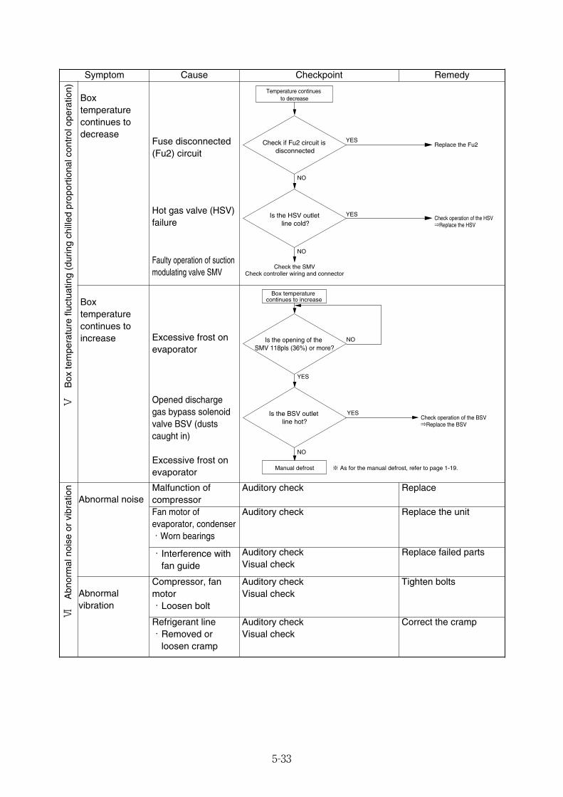
5-33
Symptom Checkpoint RemedyCause
Faulty operation of suctionmodulating valve SMV
Boxtemperaturecontinues toincrease Excessive frost on
evaporator
Opened dischargegas bypass solenoidvalve BSV (dustscaught in)
Excessive frost onevaporator
Boxtemperaturecontinues todecrease
Fuse disconnected(Fu2) circuit
Hot gas valve (HSV)failure
Replace the Fu2
Check operation of the HSV⇒Replace the HSV
Temperature continues to decrease
Check if Fu2 circuit is disconnected
Is the HSV outlet line cold?
Check the SMVCheck controller wiring and connector
YES
YES
NO
NO
NO
YES
Is the opening of the SMV 118pls (36%) or more?
Is the BSV outlet line hot?
Check operation of the BSV⇒Replace the BSV
YES
NO
Box temperature continues to increase
Manual defrost ※ As for the manual defrost, refer to page 1-19.
Refrigerant line ・Removed or
loosen cramp
Auditory checkVisual check
Correct the cramp
Abnormal noiseMalfunction ofcompressor
Auditory check Replace
Fan motor ofevaporator, condenser・Worn bearings
Auditory check Replace the unit
・Interference withfan guide
Auditory checkVisual check
Replace failed parts
Abnormalvibration
Compressor, fanmotor・Loosen bolt
Auditory checkVisual check
Tighten bolts
Ⅴ
Box
tem
pera
ture
fluc
tuat
ing
(dur
ing
chill
ed p
ropo
rtio
nal c
ontr
ol o
pera
tion)
Ⅵ
Abn
orm
al n
oise
or
vibr
atio
n
05_24-46_LXE10E100以降_E.qxd 15.3.4 11:41 AM ページ 5-33
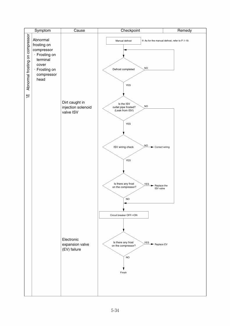
5-34
Symptom Checkpoint RemedyCause
Abnormal frosting on compressor・Frosting on
terminalcover・Frosting on
compressorhead
Dirt caught ininjection solenoidvalve ISV
Defrost completed
Is the ISV outlet pipe frosted?
(Leak from ISV)
ISV wiring check Correct wiring
Replace the ISV valve
Is there any frost on the compressor?
Is there any frost on the compressor? Replace EV
Finish
Manual defrost
Circuit breaker OFF⇒ON
NO
YES
NO
YES
NO
YES
YES
NO
YES
NO
※ As for the manual defrost, refer to P.1-19.
Electronicexpansion valve(EV) failure
Ⅶ
Abn
orm
al fr
ostin
g on
com
pres
sor
05_24-46_LXE10E100以降_E.qxd 15.3.4 11:41 AM ページ 5-34
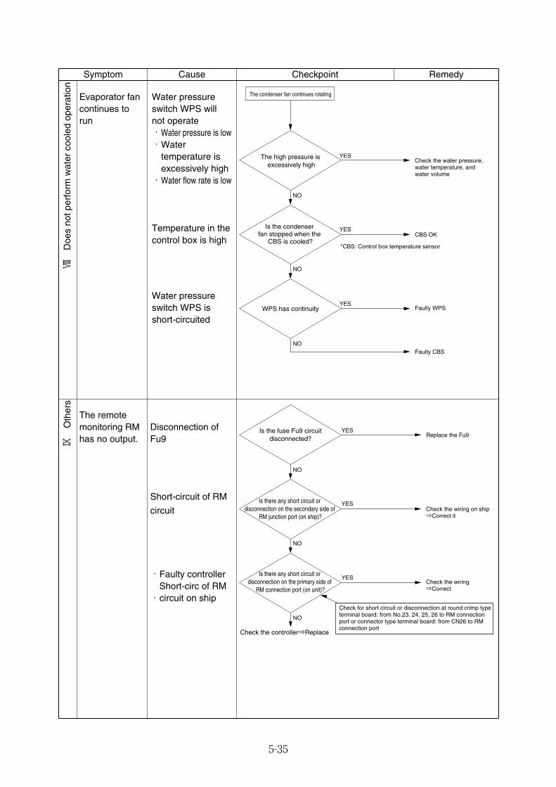
5-35
Water pressureswitch WPS willnot operate・Water pressure is low・Water
temperature isexcessively high・Water flow rate is low
The remotemonitoring RMhas no output.
Disconnection ofFu9
Short-circuit of RM
circuit
YES
YES
Is the fuse Fu9 circuit disconnected?
Replace the Fu9
Check the wiring on ship⇒Correct it
NO
NO
NO
YESCheck the wiring⇒Correct
Check the controller⇒Replace
Is there any short circuit or disconnection on the secondary side of
RM junction port (on ship)?
Is there any short circuit or disconnection on the primary side of
RM connection port (on unit)?
Check for short circuit or disconnection at round crimp type terminal board: from No.23, 24, 25, 26 to RM connection port or connector type terminal board: from CN26 to RM connection port
・Faulty controllerShort-circ of RM・circuit on ship
Symptom Cause Checkpoint Remedy
Evaporator fancontinues torun
Temperature in thecontrol box is high
Water pressureswitch WPS isshort-circuited
YES
YESIs the condenser fan stopped when the
CBS is cooled?
WPS has continuity
Check the water pressure, water temperature, and water volume
CBS OK
NO
NO
NO
YESFaulty WPS
Faulty CBS
*CBS: Control box temperature sensor
The high pressure is excessively high
The condenser fan continues rotating
Ⅷ
Doe
s no
t per
form
wat
er c
oole
d op
erat
ion
Ⅸ
Oth
ers
05_24-46_LXE10E100以降_E.qxd 15.3.4 11:41 AM ページ 5-35
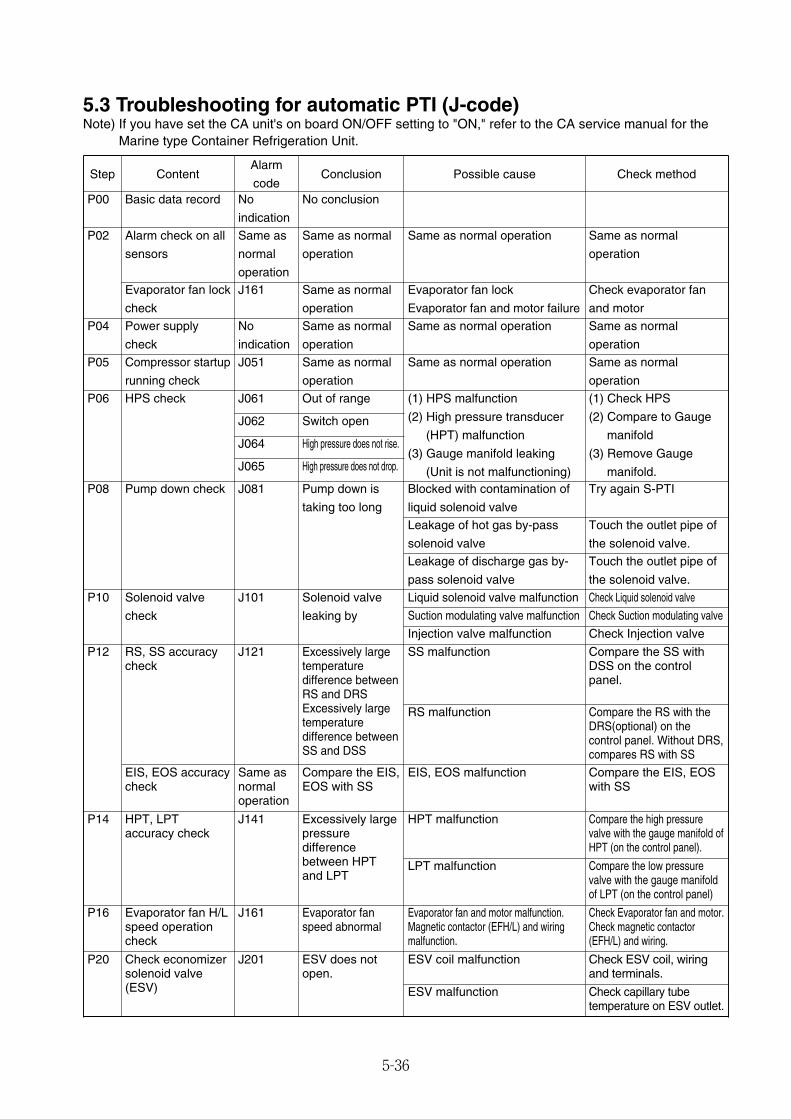
5-36
5.3 Troubleshooting for automatic PTI (J-code)Note) If you have set the CA unit's on board ON/OFF setting to "ON," refer to the CA service manual for the
Marine type Container Refrigeration Unit.
Step ContentAlarm
codeConclusion Possible cause Check method
P00 Basic data record No
indication
No conclusion
P02
Evaporator fan lock
check
J161 Same as normal
operation
Evaporator fan lock
Evaporator fan and motor failure
Check evaporator fan
and motorP04 Power supply
check
No
indication
Same as normal
operation
Same as normal operation Same as normal
operationP05 Compressor startup
running check
J051 Same as normal
operation
Same as normal operation Same as normal
operationP06 HPS check J061 Out of range (1) HPS malfunction
(2) High pressure transducer
(HPT) malfunction
(3) Gauge manifold leaking
(Unit is not malfunctioning)
(1) Check HPS
(2) Compare to Gauge
manifold
(3) Remove Gauge
manifold.P08 Pump down check J081 Pump down is
taking too long
Blocked with contamination of
liquid solenoid valve
Try again S-PTI
P10 Solenoid valve
check
J101 Solenoid valve
leaking by
Liquid solenoid valve malfunction Check Liquid solenoid valve
P12 RS, SS accuracycheck
J121 Excessively largetemperaturedifference betweenRS and DRSExcessively largetemperaturedifference betweenSS and DSS
SS malfunction Compare the SS withDSS on the controlpanel.
P14 HPT, LPTaccuracy check
J141 Excessively largepressuredifferencebetween HPTand LPT
HPT malfunction Compare the high pressurevalve with the gauge manifold ofHPT (on the control panel).
P20 Check economizersolenoid valve(ESV)
J201 ESV does notopen.
ESV coil malfunction Check ESV coil, wiringand terminals.
P16 Evaporator fan H/Lspeed operationcheck
J161 Evaporator fanspeed abnormal
Evaporator fan and motor malfunction.Magnetic contactor (EFH/L) and wiringmalfunction.
Check Evaporator fan and motor.Check magnetic contactor(EFH/L) and wiring.
J062 Switch open
J064 High pressure does not rise.
J065 High pressure does not drop.
Leakage of hot gas by-pass
solenoid valve
Touch the outlet pipe of
the solenoid valve.Leakage of discharge gas by-
pass solenoid valve
Touch the outlet pipe of
the solenoid valve.
Suction modulating valve malfunction Check Suction modulating valve
Injection valve malfunction Check Injection valve
EIS, EOS malfunction Compare the EIS, EOSwith SS
LPT malfunction Compare the low pressurevalve with the gauge manifoldof LPT (on the control panel)
ESV malfunction Check capillary tubetemperature on ESV outlet.
Alarm check on all
sensors
Same as
normal
operation
Same as normal
operation
Same as normal operation Same as normal
operation
RS malfunction Compare the RS with theDRS(optional) on thecontrol panel. Without DRS,compares RS with SS
EIS, EOS accuracycheck
Same asnormaloperation
Compare the EIS,EOS with SS
05_24-46_LXE10E100以降_E.qxd 15.3.4 11:41 AM ページ 5-36
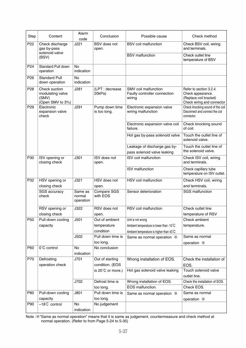
5-37
Note :※"Same as normal operation" means that it is same as judgement, countermeasure and check method atnormal operation. (Refer to from Page 5-24 to 5-35)
Step ContentAlarm
codeConclusion Possible cause Check method
P22 Check dischargegas by-passsolenoid valve(BSV)
J221 BSV does notopen.
BSV coil malfunction Check BSV coil, wiringand terminals.
P24 Standard Pull downoperation
Noindication
P26 Standard Pulldown operation
Noindication
P28 Check suctionmodulating valve(SMV)(Open SMV to 3%)
J281 (LPT : decrease20kPa)
SMV coil malfunctionFaulty controller connectionwiring
Refer to section 3.2.4.Check appearance.(Replace coil bracket)Check wiring and connector
P29 Electronicexpansion valvecheck
J291 Pump down timeis too long.
Electronic expansion valvewiring malfunction
Check knocking sound of the coilDisconnect and connect the coilconnector.
P30 ISV opening orclosing check
J301 ISV does notopen.
ISV coil malfunction Check ISV coil, wiringand terminals.
P32 HSV opening or
closing check
J321 HSV does not
open.
HSV coil malfunction Check HSV coil, wiring
and terminals.
P50 Pull-down cooling
capacity
J501 Out of ambient
temperature
condition
Unit is not wrong
Ambient temperature is lower than -10˚C
Ambient temperature is higher than 43˚C
Check ambient
temperature.
P60 0˚C control No
indication
No conclusion
P70 Defrosting
operation check
J701 Out of starting
condition. (EOS
is 20˚C or more.)
Wrong installation of EOS. Check the installation of
EOS.
P90 –18˚C control No
indication
No judgement
P80 Pull-down cooling
capacity
J801 Pull down time is
too long.Same as normal operation ※ Same as normal
operation ※
BSV malfunction Check outlet linetemperature of BSV
Electronic expansion valve coilfailure.
Check knocking soundof coil.
Hot gas by-pass solenoid valve Touch the outlet line ofsolenoid valve.
Leakage of discharge gas by-
pass solenoid valve leaking
Touch the outlet line ofthe solenoid valve.
ISV malfunction Check capillary tubetemperature on ISV outlet.
RSV coil malfunction Check outlet line
temperature of RSV
J502 Pull down time is
too long.Same as normal operation ※ Same as normal
operation ※
Hot gas solenoid valve leaking Touch solenoid valve
outlet line.J702 Defrost time is
too long.
Wrong installation of EOS. Check the installation of EOS.
EOS malfunction. Check EOS.
RSV opening or
closing check
J322 RSV does not
open.
SGS accuracycheck
Same asnormaloperation
Compare SGSwith EOS
Sensor deterioration SGS malfunction
05_24-46_LXE10E100以降_E.qxd 15.3.4 11:41 AM ページ 5-37

5-38
5.4 Emergency operation5.4.1 Controller emergency operation
In case of the controller malfunction, emergency operation can be done by using emergencyoperation kit. However, CA operation is not possible.(1) Components to be prepared (emergency operation kit)
� Short-circuit connector ... Installed in front of the controller inside the control box� Emergency magnet ... (Part No. 1896110)
(2) On-site workThe following steps are required for emergency operation.q Wiring change for short circuit operation
1) Wiring change for cutting off the power to CPU board2) Wiring change to force running of Compressor, Condenser Fan and Evaporator Fans.
* Install the short-circuit connector in front of the controller.* For the details, refer to section 5.4.2 "Controller short circuit operation"
w Opening of electronic expansion valve* The emergency magnet is used to open valve.* For the details, refer to section 5.4.3 "Electronic expansion valve emergency operation"
e Suction Modulation Valve fully open.* Use Emergency Magnet for full opening.* For details, refer to "Suction modulation valve emergency operation" in section 5.4.4.
(3) Operating condition at emergencyTemperature can not be controlled. Turn the circuit breaker on or off to maintain set temperature.
ModeAvailable function of
protection devicesOperating condition of unit
Cooling operation HPS : High pressure switch
CTP : Compressor thermal protector
� Compressor runs continuously.� Evaporator fan runs at low speed
continuously.� Condenser fan runs continuously.� Electronic expansion valve
operates at full open.� Suction modulating valve operates
at full open.
Heating operation
–––––––––––––
� Compressor stops.� Evaporator fan runs at high speed
continuously.� Condenser fan stops.
05_24-46_LXE10E100以降_E.qxd 15.3.4 11:41 AM ページ 5-38

5-39
5.4.2 Controller short circuit operation●LXE10E100F or later
SCC1-0(Yellow)
SCC1-0
CN6(Black)
CN-C1
CN-C1
CN8 SCC1-2
CN-C2
CN-C2
Check power supply reversed phase again when running the unit after having turned the power OFF.
Preparation
Caution when turning the power off
②Remove connector (black) from CN6 located on the I/O board. ③Remove connectors attached to the controller, SCC1-0 (yellow), SCC1-1
(blue), SCC1-2 (red) and SCC3 (white).
<Cooling Operation>1.Turn OFF breaker.2.Pull SCC1-10 (yellow) from CN8 and
insert SCC1-1 (blue).3.Turn ON breaker.
<Heating Operation>1.Turn OFF the breaker.2.Pull SCC1-0 (yellow) from CN8 and
insert SCC1-2 (red).3.Turn ON the breaker.
CN-C1
CN8
CN-C2
CN-C1
CN8
CN-C2
CN8
④Connect SCC1-0 (yellow) to CN-8 and SCC3 (white) to CN-C1, respectively.
⑤Turn ON the breaker.If the power supply is in reversed phase, the condenser rotates inversely.
⑥In case of reverse phase, Turn OFF the breaker and remove SCC3 (white) from CN-C1 and insert in CN-C2.
SCC1-1
SCC3
SCC1-1 (Blue)-cooling operation
SCC3 (White)-reverse phase correction socket
SCC1-2 (Red)-heating operation
Power OFF
Cooling operation
①Turn OFF the circuit breaker.
Heating operation
Forcible operation of compressor and condenser fan
Power supply reversed phase confirmation
Correct phase For reversed phase
05_24-46_LXE10E100以降_E.qxd 15.3.4 11:41 AM ページ 5-39

5-40
5.4.3 Electronic expansion valve emergency operationIf controller does not work or the electronic expansion valve coil has failed the emergency magnet canbe used to fully open electronic expansion valve.
①Disconnect the CN11-1 connector or CN11-2 connector from the power supply I/O board of thecontroller to turn off power to the electronic expansion valve.
②Locate the emergency magnet.③Remove the electronic expansion valve coil.④Bring the emergency magnet into contact with the coil mount section of the electronic expansion
valve body with indication "UP SIDE" located upward. (The emergency magnet is magneticallyattracted to the coil mount section by moving magnet located inside.)
⑤Turn the emergency magnet in the OPEN direction (clockwise) mounted on valve.→Ensure that the valve is fully open. (There is a small click sound.)
⑥Turn emergency magnet mounted on the valve 90˚ to 180˚ counterclockwise.
To shorten the operation time, it is recommended that the opening be adjusted.
Note : slightly closed if there is frost around the compressor due to the operation in wet conditions orthe degree of superheat is small.
②
○Yellow label ×Silver label
⑤
④
⑥③
①CN11-1
②CN11-2Controller body
UP SIDE
DOWN SIDE
OPEN
UP SIDE
DOWN SIDE
OPEN
Coil mount section
Emergency magnet
Main unit
Coil
Emergency magnet
(Part No.1896110)
Attention
●The silver label is not used. (The silverlabels are used for LXE10E-A, 10E-1and 10D.)
05_24-46_LXE10E100以降_E.qxd 15.3.4 11:41 AM ページ 5-40
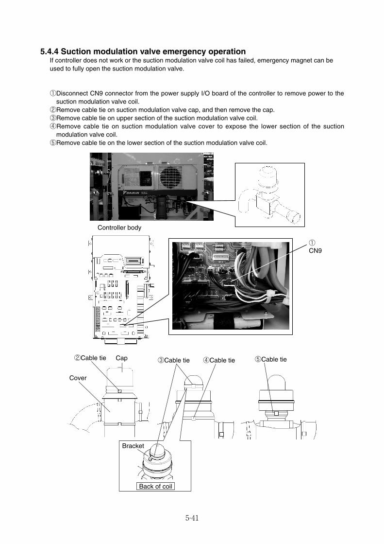
5-41
①CN9
②Cable tie Cap
Cover
③Cable tie ④Cable tie ⑤Cable tie
Bracket
Controller body
Back of coil
5.4.4 Suction modulation valve emergency operationIf controller does not work or the suction modulation valve coil has failed, emergency magnet can beused to fully open the suction modulation valve.
①Disconnect CN9 connector from the power supply I/O board of the controller to remove power to thesuction modulation valve coil.
②Remove cable tie on suction modulation valve cap, and then remove the cap.③Remove cable tie on upper section of the suction modulation valve coil.④Remove cable tie on suction modulation valve cover to expose the lower section of the suction
modulation valve coil.⑤Remove cable tie on the lower section of the suction modulation valve coil.
05_24-46_LXE10E100以降_E.qxd 15.3.4 11:41 AM ページ 5-41

5-42
⑥Locate emergency magnet.⑦Remove suction proportional coil. (Removed together with the coil's lower rubber cover)⑧Bring the emergency magnet into contact with the coil mount section of the suction modulation valve
with indication "UP SIDE" located upward. (The emergency magnet is magnetically attracted to thecoil mount section by the driving magnet located inside.)
⑨Turn the emergency magnet in the OPEN direction (clockwise) in the same place.→Ensure that the valve is fully open. (There is a small clicking sound.)
⑥
⑦
⑧⑨
○Yellow label ×Silver label
Coil mount section
Coil
Rubber cover
Emergency magnet(Part No.1896110)
UP SIDE
DOWN SIDE
OPEN
UP SIDE
DOWN SIDE
OPEN
Attention
●The silver label is not used. (The silverlabels are used for LXE10E-A, 10E-1and 10D.)
05_24-46_LXE10E100以降_E.qxd 15.3.4 11:41 AM ページ 5-42
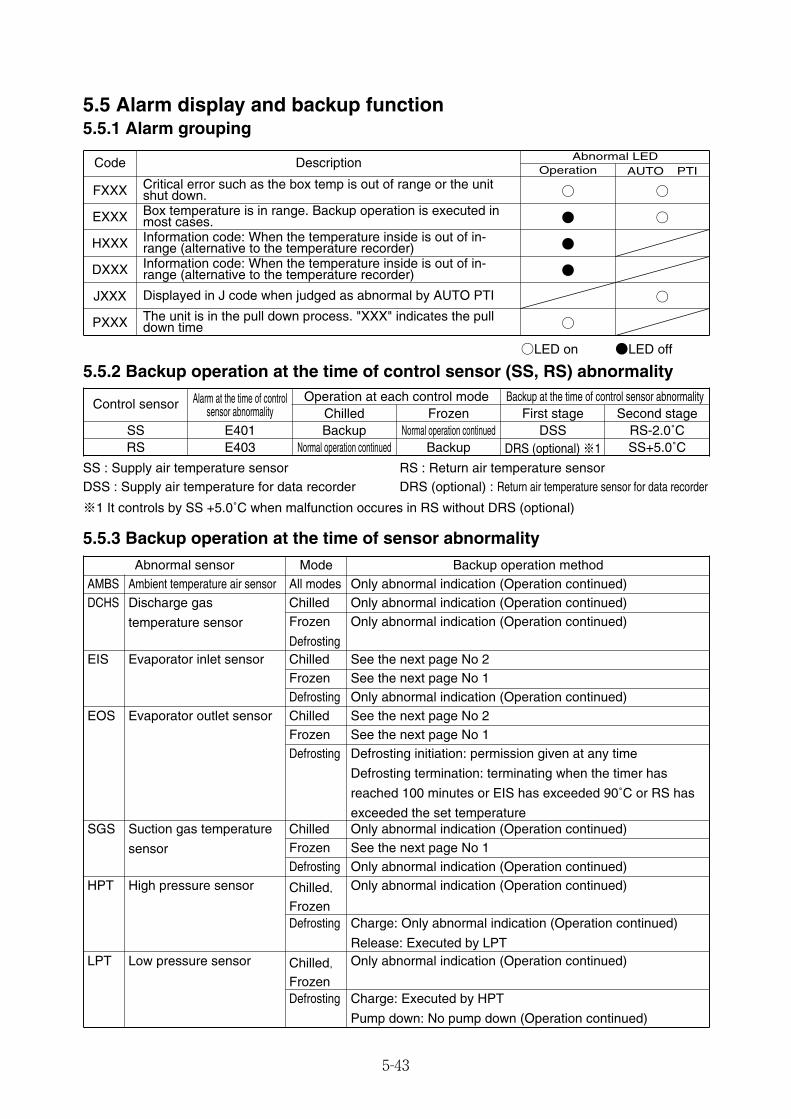
5-43
5.5.2 Backup operation at the time of control sensor (SS, RS) abnormality
Abnormal sensor Mode Backup operation methodAMBS Ambient temperature air sensor All modes Only abnormal indication (Operation continued)DCHS Discharge gas
temperature sensor
Chilled Only abnormal indication (Operation continued)Frozen
Defrosting
Only abnormal indication (Operation continued)
EIS Evaporator inlet sensor Chilled See the next page No 2
Defrosting Only abnormal indication (Operation continued)EOS Evaporator outlet sensor Chilled See the next page No 2
Defrosting Defrosting initiation: permission given at any time
Defrosting termination: terminating when the timer has
reached 100 minutes or EIS has exceeded 90˚C or RS has
exceeded the set temperatureSGS Suction gas temperature
sensor
Chilled Only abnormal indication (Operation continued)
Defrosting Only abnormal indication (Operation continued)HPT High pressure sensor Chilled,
Frozen
Only abnormal indication (Operation continued)
Defrosting Charge: Only abnormal indication (Operation continued)
Release: Executed by LPTLPT Low pressure sensor Chilled,
Frozen
Only abnormal indication (Operation continued)
Defrosting Charge: Executed by HPT
Pump down: No pump down (Operation continued)
Frozen See the next page No 1
Frozen See the next page No 1
Frozen See the next page No 1
Backup at the time of control sensor abnormalityFirst stage Second stage
DSS RS-2.0˚CDRS (optional) ※1 SS+5.0˚C
Control sensor Alarm at the time of controlsensor abnormality
Operation at each control modeChilled Frozen
SS E401 Backup Normal operation continuedRS E403 Normal operation continued Backup
5.5.3 Backup operation at the time of sensor abnormality
SS : Supply air temperature sensorDSS : Supply air temperature for data recorder
※1 It controls by SS +5.0˚C when malfunction occures in RS without DRS (optional)
RS : Return air temperature sensorDRS (optional) : Return air temperature sensor for data recorder
Code DescriptionAUTO PTI
Critical error such as the box temp is out of range or the unitshut down.Box temperature is in range. Backup operation is executed inmost cases.
Abnormal LEDOperation
FXXX ○ ○
EXXX ● ○
HXXX Information code: When the temperature inside is out of in-range (alternative to the temperature recorder) ●
DXXX Information code: When the temperature inside is out of in-range (alternative to the temperature recorder) ●
JXXX Displayed in J code when judged as abnormal by AUTO PTI ○
○LED on ●LED off
PXXX The unit is in the pull down process. "XXX" indicates the pulldown time ○
5.5 Alarm display and backup function5.5.1 Alarm grouping
05_24-46_LXE10E100以降_E.qxd 15.3.4 11:41 AM ページ 5-43
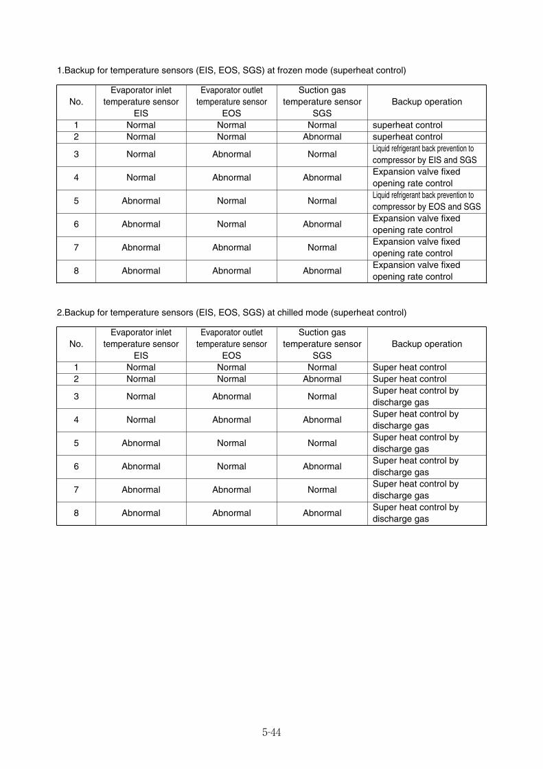
5-44
1.Backup for temperature sensors (EIS, EOS, SGS) at frozen mode (superheat control)
No.Evaporator inlet
temperature sensorEIS
NormalNormal
Suction gastemperature sensor
SGS1 Normal superheat control2 Abnormal
3 Normal NormalLiquid refrigerant back prevention to compressor by EIS and SGS
7 Abnormal NormalExpansion valve fixed opening rate control
8 Abnormal AbnormalExpansion valve fixed opening rate control
Backup operationEvaporator outlet
temperature sensorEOS
NormalNormal
Abnormal
Abnormal
Abnormal
4 Normal Abnormal AbnormalExpansion valve fixed opening rate control
5 Abnormal Normal NormalLiquid refrigerant back prevention tocompressor by EOS and SGS
6 Abnormal Normal AbnormalExpansion valve fixed opening rate control
superheat control
2.Backup for temperature sensors (EIS, EOS, SGS) at chilled mode (superheat control)
No.Evaporator inlet
temperature sensorEIS
NormalNormal
Suction gastemperature sensor
SGS1 Normal Super heat control2 Abnormal
3 Normal NormalSuper heat control bydischarge gas
7 Abnormal NormalSuper heat control bydischarge gas
8 Abnormal AbnormalSuper heat control bydischarge gas
Backup operationEvaporator outlet
temperature sensorEOS
NormalNormal
Abnormal
Abnormal
Abnormal
4 Normal Abnormal AbnormalSuper heat control bydischarge gas
5 Abnormal Normal NormalSuper heat control bydischarge gas
6 Abnormal Normal AbnormalSuper heat control bydischarge gas
Super heat control
05_24-46_LXE10E100以降_E.qxd 15.3.4 11:41 AM ページ 5-44

5-45
5.6 Backup BatteryNote) If you have set the CA unit's on board ON/OFF setting to "ON," refer to the CA service manual for the
Marine type Container Refrigeration Unit.
5.6.1 FunctionWhen main power supply is not available, backup battery can be used as power supply to display and setthe following items. Refer to section 2.2.2 (3. Battery mode).
5.6.2 Checking the remaining battery voltage 1) Checking the remaining battery voltage
The remaining battery voltage can be checked during operation in accordance with section 2.2.2 (6.Sensor indication mode). When the unit does not run or main power is not available the remaining battery voltage can be checkedsee section 2.2.2 (3. Battery mode).
The remaining voltage 7.6V or more: The battery has been charged.7.5V or less : The battery may have failed. Verify battery voltage and replace.7.1V or less : The battery has failed. Verify battery voltage and replace.
●Things to keep in mind when checking the remaining voltageMake sure that the unit has run for 14 hours at least or main power supply has recharged for 14 hoursat least with the circuit breaker ON (the unit OFF) before checking the remaining voltage. Rechargingfor 14 hours at least is a must.
Note 1: Because of the battery property, accurate remaining voltage cannot be obtained if not fullycharged.
Note 2: The remaining voltage during recharging, under the recharger's influence, is indicated (blinking)higher than it should be.
2) Rechargeable batteryThe battery life is approximately 2 years. In the event of using the battery for 2 years or more, datalogging etc. may not be executed when the power is turned off even if the LCD screen indicates that theremaining voltage is 7.6V or more.
3) The remaining voltage for dry batteries can be checked, but replace the new ones before a voyage asneeded basis such as refrigerated transport (USDA). Don’t judge by the remaining voltage.
1) Display functionReturn air temperature indication (RS)Supply air temperature indication (SS)Ventilation amount indication (FA)USDA & CTS temperature indication High pressure indication (HPT)Low pressure indication (LPT)Full-PTI record indication Short-PTI operation day record indicationChilled-PTI operation day record indicationFrozen-PTI operation day record indicationRemaining battery voltage indication (BAT)
2) Setting functionControl temperature setting (SP)Control humidity setting (RH)Defrosting interval setting (Def)
05_24-46_LXE10E100以降_E.qxd 15.3.4 11:41 AM ページ 5-45
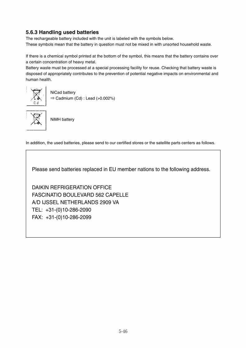
5-46
5.6.3 Handling used batteriesThe rechargeable battery included with the unit is labeled with the symbols below.These symbols mean that the battery in question must not be mixed in with unsorted household waste.
If there is a chemical symbol printed at the bottom of the symbol, this means that the battery contains overa certain concentration of heavy metal.Battery waste must be processed at a special processing facility for reuse. Checking that battery waste isdisposed of appropriately contributes to the prevention of potential negative impacts on environmental andhuman health.
NiCad battery⇒ Cadmium (Cd) : Lead (>0.002%)
NiMH battery
In addition, the used batteries, please send to our certified stores or the satellite parts centers as follows.
Please send batteries replaced in EU member nations to the following address.
DAIKIN REFRIGERATION OFFICEFASCINATIO BOULEVARD 562 CAPELLEA/D IJSSEL NETHERLANDS 2909 VATEL: +31-(0)10-286-2090FAX: +31-(0)10-286-2099
05_24-46_LXE10E100以降_E.qxd 15.3.4 11:41 AM ページ 5-46
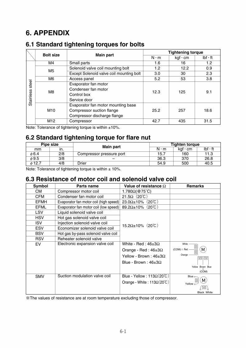
6-1
6. APPENDIX
6.1 Standard tightening torques for bolts
Bolt size Main partTightening torque
N � m kgf � cm lbf � ftM4 Small parts 1.6 16 1.2
M5Solenoid valve coil mounting bolt 1.2 12.2 0.9Except Solenoid valve coil mounting bolt 3.0 30 2.3
M6 Access panel 5.2 53 3.8Evaporator fan motor
M8Condenser fan motor
12.3 125 9.1Control boxService doorEvaporator fan motor mounting base
M10 Compressor suction flange 25.2 257 18.6Compressor discharge flange
M12 Compressor 42.7 435 31.5
Note: Tolerance of tightening torque is within ±10%.
Note: Tolerance of tightening torque is within ± 10%.
※The values of resistance are at room temperature excluding those of compressor.
Sta
inle
ssst
eel
6.2 Standard tightening torque for flare nutPipe size Main part Tighten torque
mm in. N � m kgf � cm Ibf � ftφ 6.4 2/8 Compressor pressure port 15.7 160 11.3φ 9.5 3/8 – 36.3 370 26.8φ 12.7 4/8 Drier 54.9 500 40.5
6.3 Resistance of motor coil and solenoid valve coilSymbol Parts name Value of resistance ΩCM 1.780Ω(@75˚C)
Hot gas solenoid valve coilInjection solenoid valve coil
Electronic expansion valve coil
Compressor motor coil
EFMH Evaporator fan motor coil (high speed) 23.0Ω±10%(20℃)EFML Evaporator fan motor coil (low speed) 89.2Ω±10%(20℃)LSV Liquid solenoid valve coil
15.2Ω±10%(20℃)
HSVISV
EV White - Red : 46±3ΩOrange - Red : 46±3ΩYellow - Brown : 46±3ΩBlue - Brown : 46±3Ω
SMV Suction modulation valve coil Blue - Yellow : 113Ω(20℃)Orange - White : 113Ω(20℃)
ESV Economizer solenoid valve coil
RSV Reheater solenoid valve
Remarks
Yellow Brown Blue
White
Red
Orange
(COM)
(COM)
Black
Blue
Yellow
White
BSV Hot gas by-pass solenoid valve coil
CFM Condenser fan motor coil 21.5Ω(20℃)
06_01-12_LXE10E100以降_E.qxd 2015.03.09 17:23 ページ 6-1
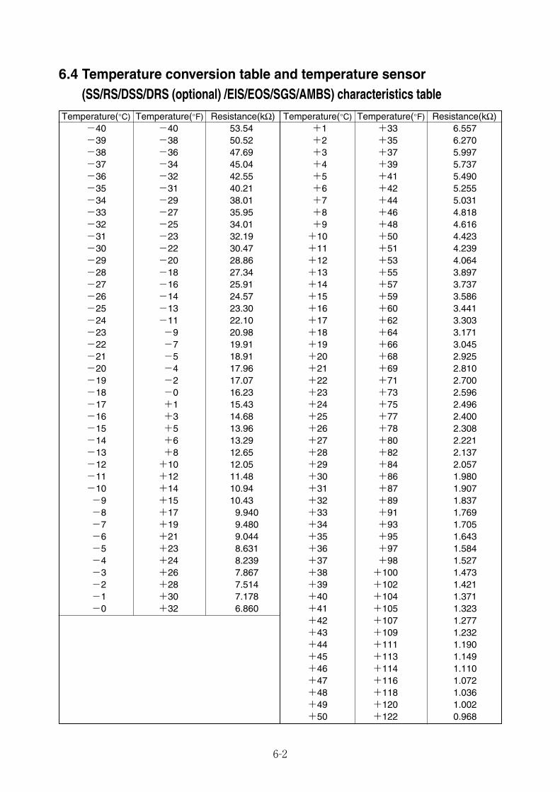
6-2
6.4 Temperature conversion table and temperature sensor(SS/RS/DSS/DRS (optional) /EIS/EOS/SGS/AMBS) characteristics table
Temperature(°C) Temperature(°F) Resistance(kΩ) Temperature(°C) Temperature(°F) Resistance(kΩ)-40 -40 53.54 +1 +33 6.557-39 -38 50.52 +2 +35 6.270-38 -36 47.69 +3 +37 5.997-37 -34 45.04 +4 +39 5.737-36 -32 42.55 +5 +41 5.490-35 -31 40.21 +6 +42 5.255-34 -29 38.01 +7 +44 5.031-33 -27 35.95 +8 +46 4.818-32 -25 34.01 +9 +48 4.616-31 -23 32.19 +10 +50 4.423-30 -22 30.47 +11 +51 4.239-29 -20 28.86 +12 +53 4.064-28 -18 27.34 +13 +55 3.897-27 -16 25.91 +14 +57 3.737-26 -14 24.57 +15 +59 3.586-25 -13 23.30 +16 +60 3.441-24 -11 22.10 +17 +62 3.303-23 -9 20.98 +18 +64 3.171-22 -7 19.91 +19 +66 3.045-21 -5 18.91 +20 +68 2.925-20 -4 17.96 +21 +69 2.810-19 -2 17.07 +22 +71 2.700-18 -0 16.23 +23 +73 2.596-17 +1 15.43 +24 +75 2.496-16 +3 14.68 +25 +77 2.400-15 +5 13.96 +26 +78 2.308-14 +6 13.29 +27 +80 2.221-13 +8 12.65 +28 +82 2.137-12 +10 12.05 +29 +84 2.057-11 +12 11.48 +30 +86 1.980-10 +14 10.94 +31 +87 1.907-9 +15 10.43 +32 +89 1.837-8 +17 9.940 +33 +91 1.769-7 +19 9.480 +34 +93 1.705-6 +21 9.044 +35 +95 1.643-5 +23 8.631 +36 +97 1.584-4 +24 8.239 +37 +98 1.527-3 +26 7.867 +38 +100 1.473-2 +28 7.514 +39 +102 1.421-1 +30 7.178 +40 +104 1.371-0 +32 6.860 +41 +105 1.323
+42 +107 1.277+43 +109 1.232+44 +111 1.190+45 +113 1.149+46 +114 1.110+47 +116 1.072+48 +118 1.036+49 +120 1.002+50 +122 0.968
06_01-12_LXE10E100以降_E.qxd 2015.03.09 17:23 ページ 6-2
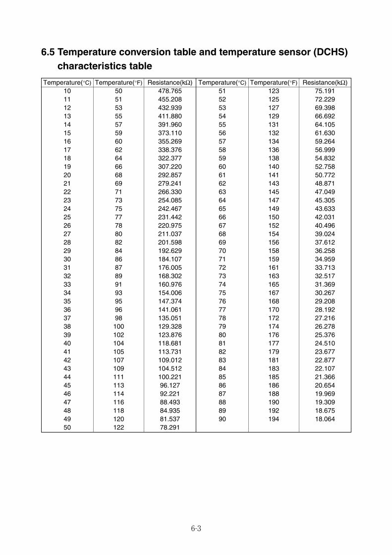
6-3
6.5 Temperature conversion table and temperature sensor (DCHS)characteristics table
Temperature(°C) Temperature(°F) Resistance(kΩ) Temperature(°C) Temperature(°F) Resistance(kΩ)10 50 478.765 51 123 75.191 11 51 455.208 52 125 72.229 12 53 432.939 53 127 69.398 13 55 411.880 54 129 66.692 14 57 391.960 55 131 64.105 15 59 373.110 56 132 61.630 16 60 355.269 57 134 59.264 17 62 338.376 58 136 56.999 18 64 322.377 59 138 54.832 19 66 307.220 60 140 52.758 20 68 292.857 61 141 50.772 21 69 279.241 62 143 48.871 22 71 266.330 63 145 47.049 23 73 254.085 64 147 45.305 24 75 242.467 65 149 43.633 25 77 231.442 66 150 42.031 26 78 220.975 67 152 40.496 27 80 211.037 68 154 39.024 28 82 201.598 69 156 37.612 29 84 192.629 70 158 36.258 30 86 184.107 71 159 34.959 31 87 176.005 72 161 33.713 32 89 168.302 73 163 32.517 33 91 160.976 74 165 31.369 34 93 154.006 75 167 30.267 35 95 147.374 76 168 29.208 36 96 141.061 77 170 28.192 37 98 135.051 78 172 27.216 38 100 129.328 79 174 26.278 39 102 123.876 80 176 25.376 40 104 118.681 81 177 24.510 41 105 113.731 82 179 23.677 42 107 109.012 83 181 22.877 43 109 104.512 84 183 22.107 44 111 100.221 85 185 21.366 45 113 96.127 86 186 20.654 46 114 92.221 87 188 19.969 47 116 88.493 88 190 19.309 48 118 84.935 89 192 18.675 49 120 81.537 90 194 18.064 50 122 78.291
06_01-12_LXE10E100以降_E.qxd 2015.03.09 17:23 ページ 6-3
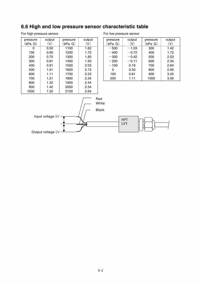
6-4
pressure output pressure output(kPa・G) (V) (kPa・G) (V)-500 -1.03 300 1.42-400 -0.72 400 1.72-300 -0.42 500 2.03-200 -0.11 600 2.34-100 0.19 700 2.64
0 0.50 800 2.95100 0.81 900 3.25200 1.11 1000 3.56
6.6 High and low pressure sensor characteristic table
pressure output pressure output(kPa・G) (V) (kPa・G) (V)
0 0.50 1100 1.62100 0.60 1200 1.72200 0.70 1300 1.83300 0.81 1400 1.93400 0.91 1500 2.03500 1.01 1600 2.13600 1.11 1700 2.23700 1.21 1800 2.34800 1.32 1900 2.44900 1.42 2000 2.54
1000 1.52 2100 2.64
For low pressure sensor
Input voltage 5V
RedWhite
Black
Output voltage 5V
LPTHPT
For high pressure sensor
06_01-12_LXE10E100以降_E.qxd 2015.03.09 17:23 ページ 6-4
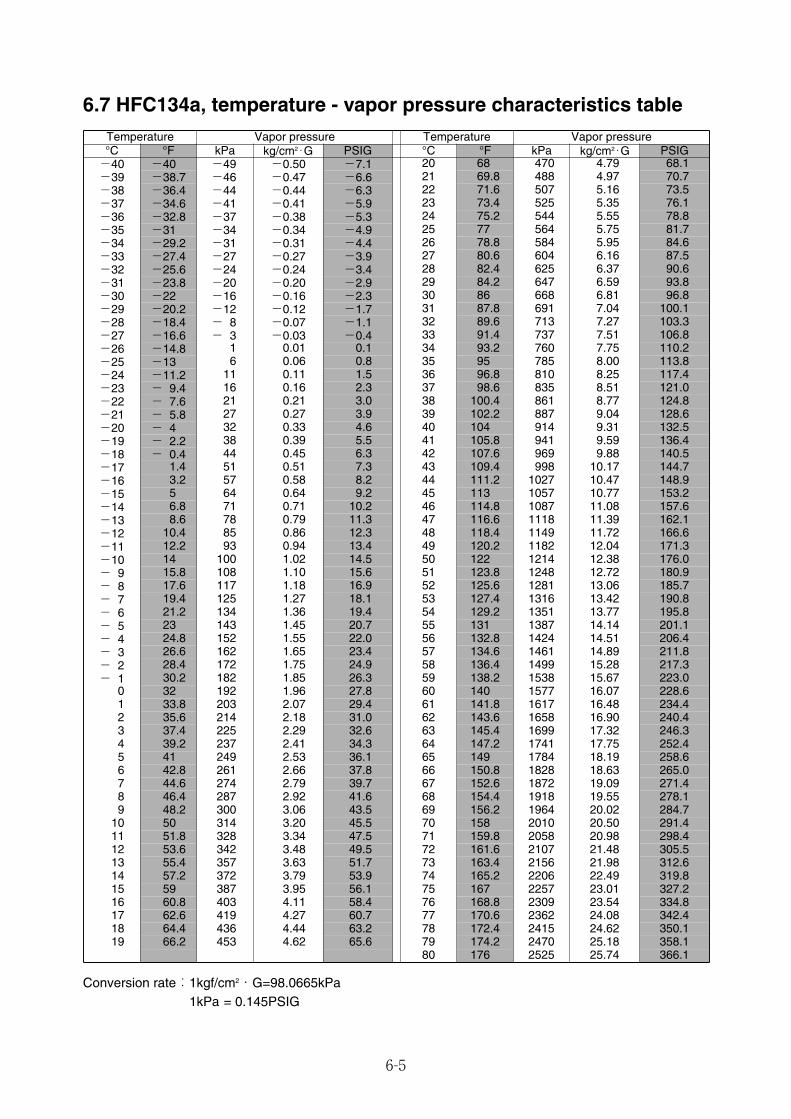
6-5
6.7 HFC134a, temperature - vapor pressure characteristics table
Conversion rate:1kgf/cm2・G=98.0665kPa1kPa = 0.145PSIG
Temperature Vapor pressure Temperature Vapor pressure°C °F kPa kg/cm2・G °C °F kPa kg/cm2・G-40 -40 -49 -0.50 -7.1 20 68 470 4.79 68.1-39 -38.7 -46 -0.47 -6.6 21 69.8 488 4.97 70.7-38 -36.4 -44 -0.44 -6.3 22 71.6 507 5.16 73.5-37 -34.6 -41 -0.41 -5.9 23 73.4 525 5.35 76.1-36 -32.8 -37 -0.38 -5.3 24 75.2 544 5.55 78.8-35 -31 -34 -0.34 -4.9 25 77 564 5.75 81.7-34 -29.2 -31 -0.31 -4.4 26 78.8 584 5.95 84.6-33 -27.4 -27 -0.27 -3.9 27 80.6 604 6.16 87.5-32 -25.6 -24 -0.24 -3.4 28 82.4 625 6.37 90.6-31 -23.8 -20 -0.20 -2.9 29 84.2 647 6.59 93.8-30 -22 -16 -0.16 -2.3 30 86 668 6.81 96.8-29 -20.2 -12 -0.12 -1.7 31 87.8 691 7.04 100.1-28 -18.4 - 8 -0.07 -1.1 32 89.6 713 7.27 103.3-27 -16.6 - 3 -0.03 -0.4 33 91.4 737 7.51 106.8-26 -14.8 1 0.01 0.1 34 93.2 760 7.75 110.2-25 -13 6 0.06 0.8 35 95 785 8.00 113.8-24 -11.2 11 0.11 1.5 36 96.8 810 8.25 117.4-23 - 9.4 16 0.16 2.3 37 98.6 835 8.51 121.0-22 - 7.6 21 0.21 3.0 38 100.4 861 8.77 124.8-21 - 5.8 27 0.27 3.9 39 102.2 887 9.04 128.6-20 - 4 32 0.33 4.6 40 104 914 9.31 132.5-19 - 2.2 38 0.39 5.5 41 105.8 941 9.59 136.4-18 - 0.4 44 0.45 6.3 42 107.6 969 9.88 140.5-17 1.4 51 0.51 7.3 43 109.4 998 10.17 144.7-16 3.2 57 0.58 8.2 44 111.2 1027 10.47 148.9-15 5 64 0.64 9.2 45 113 1057 10.77 153.2-14 6.8 71 0.71 10.2 46 114.8 1087 11.08 157.6-13 8.6 78 0.79 11.3 47 116.6 1118 11.39 162.1-12 10.4 85 0.86 12.3 48 118.4 1149 11.72 166.6-11 12.2 93 0.94 13.4 49 120.2 1182 12.04 171.3-10 14 100 1.02 14.5 50 122 1214 12.38 176.0- 9 15.8 108 1.10 15.6 51 123.8 1248 12.72 180.9- 8 17.6 117 1.18 16.9 52 125.6 1281 13.06 185.7- 7 19.4 125 1.27 18.1 53 127.4 1316 13.42 190.8- 6 21.2 134 1.36 19.4 54 129.2 1351 13.77 195.8- 5 23 143 1.45 20.7 55 131 1387 14.14 201.1- 4 24.8 152 1.55 22.0 56 132.8 1424 14.51 206.4- 3 26.6 162 1.65 23.4 57 134.6 1461 14.89 211.8- 2 28.4 172 1.75 24.9 58 136.4 1499 15.28 217.3- 1 30.2 182 1.85 26.3 59 138.2 1538 15.67 223.0
0 32 192 1.96 27.8 60 140 1577 16.07 228.61 33.8 203 2.07 29.4 61 141.8 1617 16.48 234.42 35.6 214 2.18 31.0 62 143.6 1658 16.90 240.43 37.4 225 2.29 32.6 63 145.4 1699 17.32 246.34 39.2 237 2.41 34.3 64 147.2 1741 17.75 252.45 41 249 2.53 36.1 65 149 1784 18.19 258.66 42.8 261 2.66 37.8 66 150.8 1828 18.63 265.07 44.6 274 2.79 39.7 67 152.6 1872 19.09 271.48 46.4 287 2.92 41.6 68 154.4 1918 19.55 278.19 48.2 300 3.06 43.5 69 156.2 1964 20.02 284.7
10 50 314 3.20 45.5 70 158 2010 20.50 291.411 51.8 328 3.34 47.5 71 159.8 2058 20.98 298.412 53.6 342 3.48 49.5 72 161.6 2107 21.48 305.513 55.4 357 3.63 51.7 73 163.4 2156 21.98 312.614 57.2 372 3.79 53.9 74 165.2 2206 22.49 319.815 59 387 3.95 56.1 75 167 2257 23.01 327.216 60.8 403 4.11 58.4 76 168.8 2309 23.54 334.817 62.6 419 4.27 60.7 77 170.6 2362 24.08 342.418 64.4 436 4.44 63.2 78 172.4 2415 24.62 350.119 66.2 453 4.62 65.6 79 174.2 2470 25.18 358.1
80 176 2525 25.74 366.1
PSIG PSIG
06_01-12_LXE10E100以降_E.qxd 2015.03.09 17:23 ページ 6-5

6.8 USDA sensor characteristics table●NTC type USDA Sensor Characteristics, USDA1, USDA2, USDA3, CTS
(Option)
Set sensor type "2" in ※12 Optional condition setting mode in paragraph 2.2 for NTC type USDA sensor.
6-6
Temperature(°C) Temperature(°F) Resistance(kΩ) Temperature(°C) Temperature(°F) Resistance(kΩ)-20 -4 97.391 10 50 19.893-19 -2 91.883 11 52 18.964-18 0 86.721 12 54 18.083-17 1 81.882 13 55 17.249-16 3 77.343 14 57 16.457-15 5 73.034 15 59 15.709-14 7 69.087 16 61 14.995-13 9 65.333 17 63 14.320-12 10 61.805 18 64 13.678-11 12 58.491 19 66 13.069-10 14 55.379 20 68 12.491-9 16 62.442 21 70 11.041-8 18 49.684 22 72 11.419
-6 21 44.641 24 75 10.450-5 23 42.338 25 77 10.001-4 25 40.167 26 79 8.574-3 27 38.120 27 81 8.157-2 28 36.190 28 82 8.779-1 30 34.369 29 84 8.411
0 32 32.651 30 86 8.0601 34 31.028 31 88 7.7252 36 29.494 32 90 7.4063 37 28.047 33 91 7.1024 39 25.678 34 93 6.8125 41 25.385 35 95 6.5356 43 24.162 36 97 6.2717 45 23.005 37 99 6.2008 46 21.910 38 100 5.779
3P156427A
-7 19 47.087 23 73 10.922
9 48 20.874 39 102 5.550
Receptacle for NTC
setting "2"
06_01-12_LXE10E100以降_E.qxd 2015.03.09 17:23 ページ 6-6
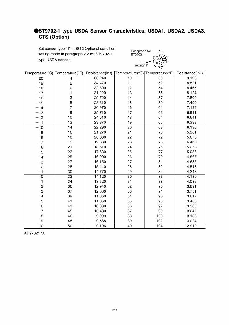
6-7
●ST9702-1 type USDA Sensor Characteristics, USDA1, USDA2, USDA3,CTS (Option)
Set sensor type "1" in ※12 Optional condition setting mode in paragraph 2.2 for ST9702-1
type USDA sensor.
Temperature(°C) Temperature(°F) Resistance(kΩ) Temperature(°C) Temperature(°F) Resistance(kΩ)-20 -4 36.240 10 50 9.196-19 -2 34.470 11 52 8.821-18 0 32.800 12 54 8.465
-16 3 29.720 14 57 7.800-15 5 28.310 15 59 7.490-14 7 26.970 16 61 7.194-13 9 25.710 17 63 6.911-12 10 24.510 18 64 6.641
-10 14 22.290 20 68 6.136-9 16 21.270 21 70 5.901-8 18 20.300 22 72 5.675-7 19 19.380 23 73 6.460-6 21 18.510 24 75 5.253
-4 25 16.900 26 79 4.867-3 27 16.150 27 81 4.685-2 28 15.440 28 82 4.513-1 30 14.770 29 84 4.348
0 32 14.120 30 86 4.1891 34 13.520 31 88 4.0362 36 12.940 32 90 3.8913 37 12.380 33 91 3.7514 39 11.860 34 93 3.6175 41 11.360 35 95 3.4886 43 10.880 36 97 3.3657 45 10.430 37 99 3.2478 46 9.999 38 100 3.1339 48 9.588 39 102 3.024
AD970217A
-5 23 17.680 25 77 5.056
10 50 9.196 40 104 2.919
Receptacle for ST9702-1
setting "1"
-11 12 23.370 19 66 6.383
-17 1 31.220 13 55 8.124
06_01-12_LXE10E100以降_E.qxd 2015.03.09 17:23 ページ 6-7
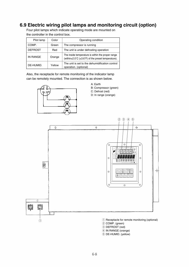
6-8
Pilot lamp Color Operating condition
COMP. Green The compressor is running
DEFROST Red The unit is under defrosting operation
IN RANGE OrangeThe inside temperature is within the proper range(within±2.0˚C (±3.6˚F) of the preset temperature).
DE-HUMID. YellowThe unit is set to the dehumidification controloperation. (optional)
6.9 Electric wiring pilot lamps and monitoring circuit (option)Four pilot lamps which indicate operating mode are mounted onthe controller in the control box.
A: EarthB: Compressor (green)C: Defrost (red)D: In range (orange)
q Receptacle for remote monitoring (optional)w COMP. (green)e DEFROST (red)r IN RANGE (orange)t DE-HUMID. (yellow)
Also, the receptacle for remote monitoring of the indicator lampcan be remotely mounted. The connection is as shown below.
w
q
e r t
3
1
2
ALARM RH
DE-HUMID.
b
-12
C
F
SP-5
OVER
HOURS
-1 -4 -6 -2 -3 -5
IN
2
SYSTEM
R.H.
DEFROST
C
C
-4
RANGE
%
-2
IN
OPERATION
RANGE
SUPPLY
DAIKIN CONTAINER
DAYS
1
° °
-10
UNDER
RETURN
-6 -8
/ COMP.
SP+ 5
DECOS ELECTRONIC
G-SET ON/OFF
ENTER/ESC SET
DISPLAY
DOWN
SELECT
UP
UNIT
S
DEFROST MANUAL
SELECT
06_01-12_LXE10E100以降_E.qxd 2015.03.09 17:23 ページ 6-8

6-9
6.10 Fuse protection table
Protection of:Fuse 1 (250V, 10A) • High pressure switch (HPS)
• Compressor contactor (CC)• Evaporator fan contactor high speed (EFH)• Evaporator fan contactor low speed (EFL)• Condenser fan contactor (CFC)• Compressor terminal protector (CTP)• Phase correction contactor (PCC1, PCC2)
Fuse 2 (250V, 10A) • Gas bypass solenoid valve (BSV)• Reheater solenoid valve (RSV) for dehumidification
Fuse 3 (250V, 10A) • Hot gas solenoid valve (HSV)• Liquid solenoid valve (LSV)• Injection solenoid valve (ISV)• Economizer solenoid valve (ESV)
Fuse 4 (250V, 10A) • ModemFuse 6 (250V, 10A) • Recorder
Fuse 9 (250V, 10A) • Remote monitoring receptacle (RM)
Fuse 7 (250V, 10A) • CPU board• Electronic expansion valve (EV)• Suction modulating valve (SMV)• LED display• LCD screen
Fuse 8 (250V, 10A) • Spare
06_01-12_LXE10E100以降_E.qxd 2015.03.09 17:23 ページ 6-9

6-10
MEMO
06_01-12_LXE10E100以降_E.qxd 2015.03.09 17:23 ページ 6-10

6-11
MEMO
06_01-12_LXE10E100以降_E.qxd 2015.03.09 17:23 ページ 6-11

6-12
MEMO
06_01-12_LXE10E100以降_E.qxd 2015.03.09 17:23 ページ 6-12
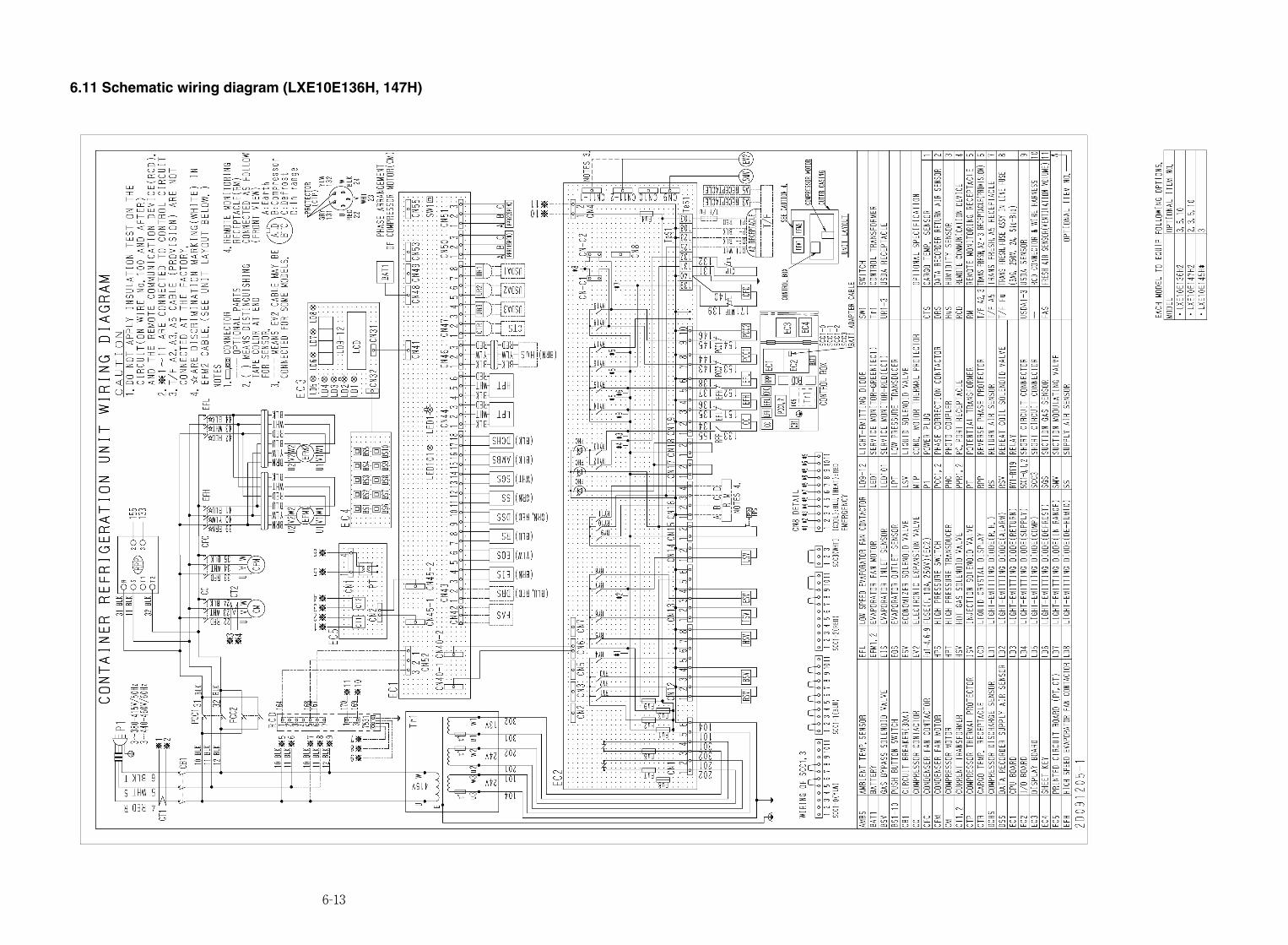
6-13
6.11 Schematic wiring diagram (LXE10E136H, 147H)
06_13-14_LXE10E100以降_E_A3.qxd 2015.03.09 17:24 ページ 6-13
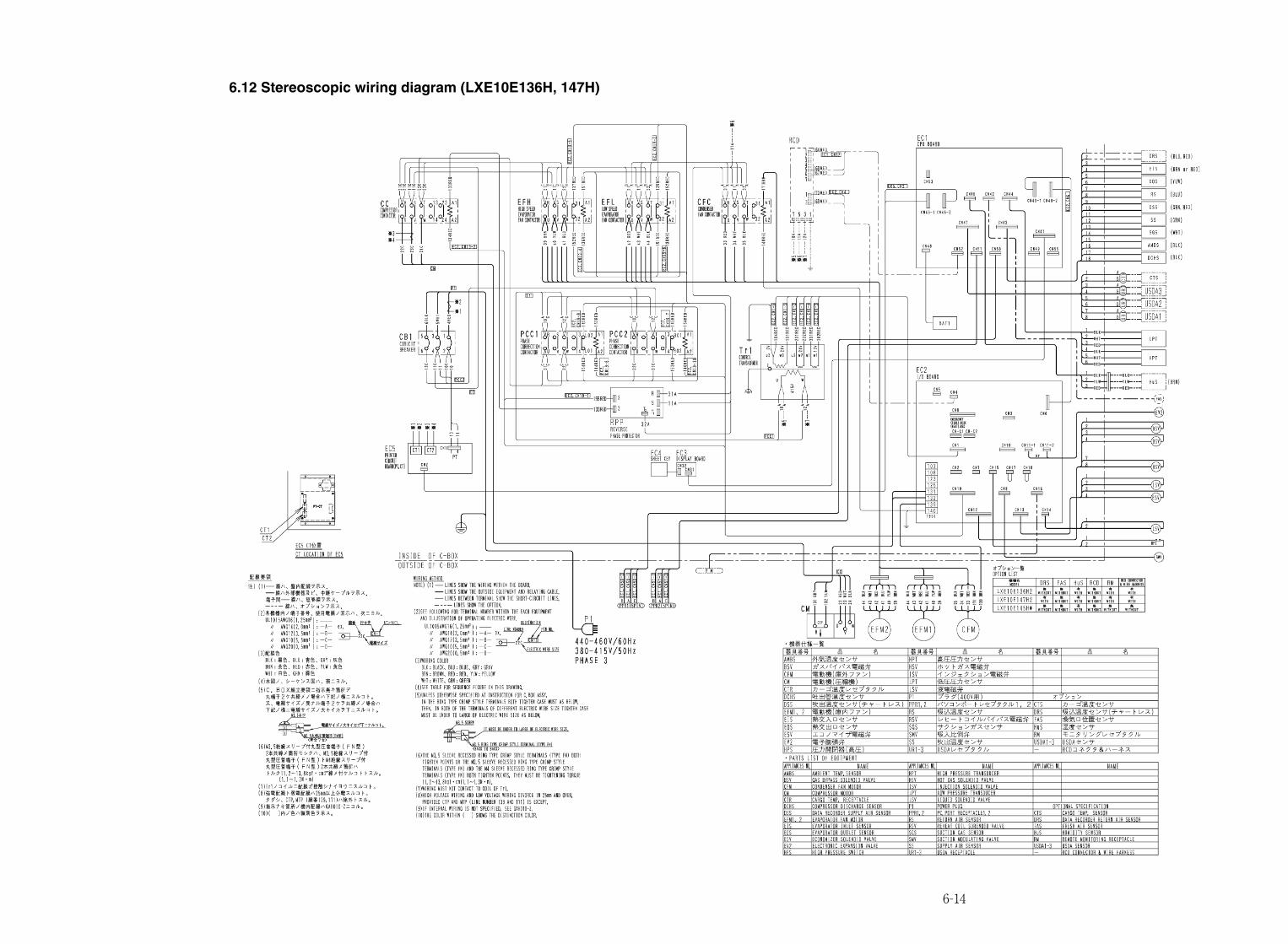
6-14
6.12 Stereoscopic wiring diagram (LXE10E136H, 147H)
06_13-14_LXE10E100以降_E_A3.qxd 2015.03.09 17:24 ページ 6-14
TR15-02
(2015.03.00150)NK$5,00
Marine type C
ontainer Refrigeration U
nitS
ervice Manual
LX
E10E
100 or later TR 15-02
Marine typeContainer Refrigeration Unit
Service Manual
Head Office. Umeda Center Bldg., 4-12, Nakazaki-Nishi 2-chome, Kita-ku, Osaka, 530-8323 Japan.
Tel: 06-6373-4338
Fax: 06-6373-7297
Tokyo Office. JR Shinagawa East Bldg., 11F 18-1, Konan 2-chome, Minato-ku Tokyo, 108-0075 Japan.
Tel: 03-6716-0420
Fax: 03-6716-0230
LXE10E100 or later(DECOSⅢh)
+H1-4_web・オンデマンド用.qxd 2015.03.11 15:27 ページ 1


![Refrigeration Basicswte[1]](https://img.pdfslide.tips/doc/110x75/577d380f1a28ab3a6b97010a/refrigeration-basicswte1.jpg)