Embed Size (px)
Citation preview
TR03-02
ダイキン海上コンテナ冷凍装置Marine type Container Refrigeration Unit
LXE10E-A18
サービスガイド・パーツリスト
Service Manual・Parts List
オプション機能編・Optional Functions
1
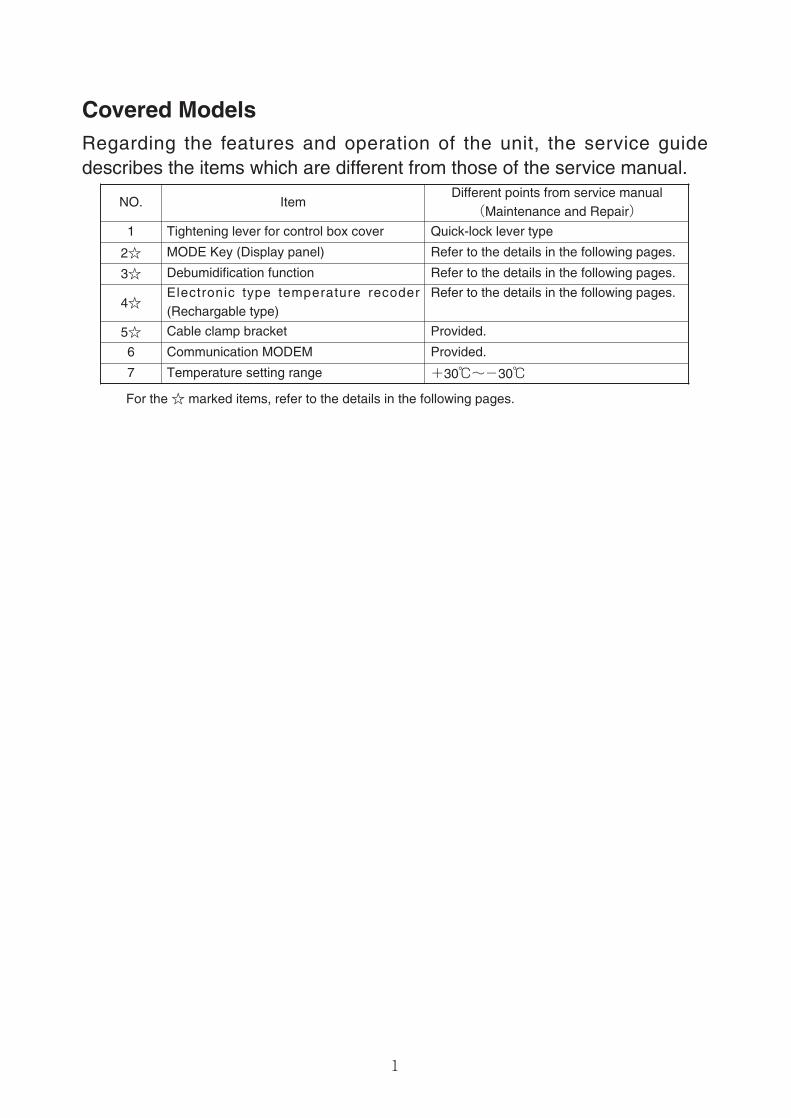
Covered ModelsRegarding the features and operation of the unit, the service guidedescribes the items which are different from those of the service manual.
NO. ItemDifferent points from service manual(Maintenance and Repair)
1 Tightening lever for control box cover Quick-lock lever type
2☆ MODE Key (Display panel) Refer to the details in the following pages.
3☆ Debumidification function Refer to the details in the following pages.
4☆Electronic type temperature recoder(Rechargable type)
Refer to the details in the following pages.
For the ☆ marked items, refer to the details in the following pages.
5☆ Cable clamp bracket Provided.
6 Communication MODEM Provided.
7 Temperature setting range +30℃~-30℃
2
CONTENTS
SAFETY PRECAUTIONS• Danger………………………………………………3• Warning ……………………………………………4• Caution………………………………………………5
1. BASIC OPERATION ……………………………1-11.1 Operation range ………………………………1-1
☆1.2 Names of components ………………………1-11.3 Operation of refrigeration unit ………………1-2
1.3.1 Starting operation ………………………1-21.3.2 Checking during operation………………1-51.3.3 Maintenance after operation……………1-5
☆1.4 Basic operation of electric controller ………1-61.4.1 Control panel ……………………………1-6
1.4.2 Operation procedure ………………………1-81.4.2.1 Current (Operation state) indication
mode …………………………………1-81.4.2.2 Operation setting mode ……………1-91.4.2.3 Battery mode ………………………1-101.4.2.4 G-SET operation and manual defrost
operation……………………………1-111.4.3 Operation mode and control …………1-11
2. DATA OF REFRIGERATION UNIT ……………2-12.1 Main specifications……………………………2-12.2 Names of components ………………………2-2
2.2.1 Outside ……………………………………2-22.2.2 Inside………………………………………2-32.2.3 Control box ………………………………2-4
2.3 Set point of functional parts and protectivedevices…………………………………………2-5
2.4 Operation pressure and running current……2-63. OPERATION MODES AND CONTROL ………3-1
3.1 Frozen operation………………………………3-23.2 Chilled and partial frozen operation…………3-43.3 Defrosting operation …………………………3-63.4 Common control ………………………………3-9
4. ELECTRONIC CONTROLLER …………………4-14.1 Function ………………………………………4-14.2 Operation procedure …………………………4-3
☆ 4.2.1 Operation procedure flow chart…………4-34.2.2 Mode operation procedure………………4-7
4.3 Alarm display and back-up function ………4-294.3.1 Alarm list…………………………………4-294.3.2 Alarm code list during PTI(Pre-Trip
Inspection) ………………………………4-304.3.3 Back-up function code with sensor
malfunction………………………………4-314.4 Battery ………………………………………4-33
4.4.1 Specifications of battery ………………4-334.4.2 Battery replacement date………………4-334.4.3 Battery replacement procedure ………4-33
4.5 Information interchange with personal computer…4-344.5.1 Data logging ……………………………4-354.5.2 Software configuratioin…………………4-36
4.6 Inspection procedure of the electronic controller…4-384.7 Controller replacement and initial setting…4-39
4.7.1 Controller replacement…………………4-394.7.2 Initial setting of controller………………4-41
4.8 Optional ………………………………………4-415. PTI(Pre-Trip Inspection) AND PERIODIC
INSPECTION………………………………………5-15.1 Inspection item ………………………………5-25.2 Automatic PTI(Pre-Trip Inspection)…………5-5
5.2.1 Short PTI (S.PTI)…………………………5-65.2.2 Full PTI (F.PTI) …………………………5-75.2.3 Alarm list during PTI(Pre-Trip Inspection) 5-85.2.4 Manual check (M.CHECK)………………5-9
6. CHARTLESS FUNCTION ………………………6-16.1 Chart indication mode ………………………6-16.2 Temperature record scroll indication function ……6-36.3 Alarm record scroll indication function………6-56.4 Chartless code display function ……………6-6
6.4.1 P code ……………………………………6-66.4.2 H code ……………………………………6-66.4.3 d code ……………………………………6-66.4.4 List of chartless code ……………………6-7
7. MAIN COMPONENTS AND MAINTENANCE…7-17.1 Components related with refrigeration circuit…7-1
7.1.1 Scroll compressor ………………………7-17.1.2 Air-cooled condenser and evaporator…7-27.1.3 Fusible plug ………………………………7-27.1.4 Dryer ………………………………………7-37.1.5 Liquid/moisture indicator ………………7-37.1.6 Electronic expansion valve ……………7-47.1.7 Suction modulation valve ………………7-57.1.8 Solenoid valve……………………………7-67.1.9 Discharge pressure regulating valve …7-77.1.10 Check valve ……………………………7-87.1.11 High-pressure switch (HPS) …………7-87.1.12 Low pressure transducer (LPT) ………7-97.1.13 High pressure transducer (HPT)………7-9
7.2 Fan and fan motor …………………………7-107.3 PT and CT board ……………………………7-11
8. Maintenance service ……………………………8-18.1 Collection of refrigerant ………………………8-18.2 Installation and removal of gauge manifold 8-1
☆8.3 Automatic pump down ………………………8-38.4 Replacement and charge of refrigerant ……8-58.5 Vacuum dehydrating …………………………8-7
9. OPTIONAL DEVICES ……………………………9-19.1 Electronic temperature recorder ……………9-19.2 USDA receptacle and sensor ………………9-39.3 Trans FRESH …………………………………9-5
10. TROUBLESHOOTING…………………………10-110.1 Refrigeration system and electrical system 10-110.2 Alarm codes on electronic controller ……10-410.3 Troubleshooting for automatic PTI ………10-810.4 Diagnosis based on the recording chart 10-1010.5 Emergency operation ……………………10-13
10.5.1 Emergency operation of controller…10-1310.5.2 Short circuit operation of controller 10-1410.5.3 Emergency operation of electronic
expansion valve ……………………10-1710.5.4 Emergency operation of suction
modulating valve ……………………10-1710.5.5 Emergency operation of supplyf � creturn
air temperature sensors (optional)…10-1811. APPENDIX………………………………………11-1
11.1 Standard tightening torques for bolts ……11-111.2 Standard tightening torques for flare nuts …11-111.3 Resistance of motor coil and solenoid valve
coil……………………………………………11-111.4 HFC134a, temperature-vapor pressure
characteristics table ………………………11-211.5 Temperature conversion table and
temperature sensor(SS/RS/DSS/DRS/RSS/RRS/EIS/EOS/SGS/AMBS) characteristics table………………11-3
11.6 Temperature conversion table and temperaturesensor(DCHS) characteristics table ………11-4
11.7 High pressure transducer characteristics table…11-411.8 Low pressure transducer characteristics table…11-4
☆11.9 Piping diagram ……………………………11-511.10 Pilot lamps and monitoring circuit………11-6
☆11.11 Schematic wiring diagram ………………11-711.12 Stereoscopic wiring diagram ……………11-8
*Diffirences from standard model service manual (TR01-09) are marked with ☆
☆
3
CONTENTS
1. NAMES OF COMPONENTS ……………………………………………5
1.1 Outside…………………………………………………………………5
1.2 Inside …………………………………………………………………6
2. BASIC OPERATION OF ELECTRONIC CONTROLLER ……………7
2.1 Control panel …………………………………………………………7
3. OPERATION PROCEDURE………………………………………………8
3.1 Operation procedure flow chart ……………………………………8
4. G-SET OPERATION/AUTOMATIC PUMP DOWN
OPERATION MODE/DEHUMIDIFICATION ON-A・OFF SETTING …9
5. DEHUMIDIFICATION CONTROL SETTING …………………………11
5.1 Description of setting ………………………………………………11
5.2 Dehumidification control ……………………………………………12
6. TEMPERATURE SENSOR………………………………………………13
6.1 Sensor calibration……………………………………………………13
7. AUTOMATIC PUMP DOWN ……………………………………………14
8. CABLE CLAMP BRACKET ……………………………………………15
9. MANUAL CHECK SELECTION MODE ………………………………16
10. ELECTRONIC TEMPERATURE RECORDER ………………………17
11. APPENDIX ………………………………………………………………19
11.1 Refrigerant piping diagram ………………………………………19
11.2 Schematic wirring diagram ………………………………………20
11.3 Stereoscopic wiring diagram………………………………………21
4
CAUTION
Temperature recorder box cover
Quick-lock lever
Control box cover
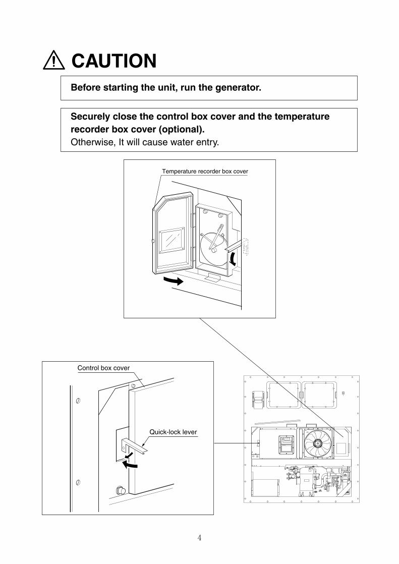
Before starting the unit, run the generator.
Securely close the control box cover and the temperaturerecorder box cover (optional).Otherwise, It will cause water entry.
5
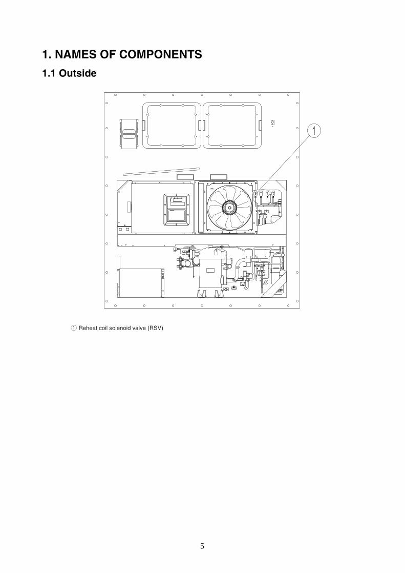
1. NAMES OF COMPONENTS
1.1 Outside
q Reheat coil solenoid valve (RSV)
1
6
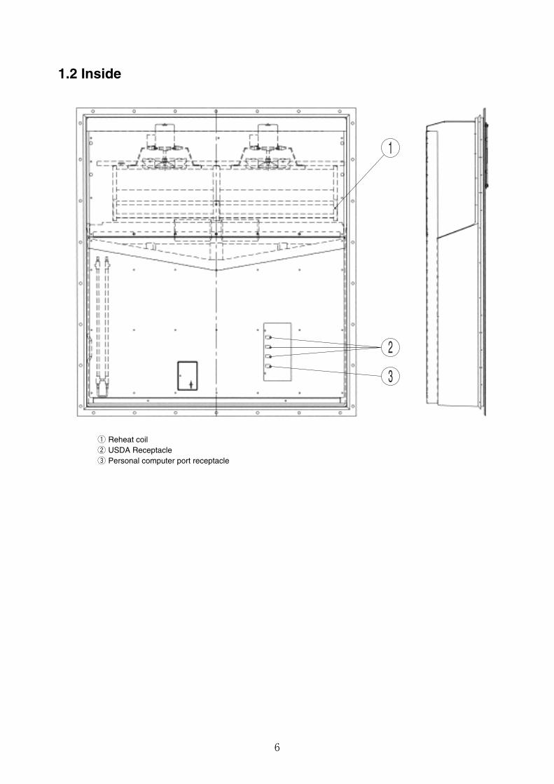
1.2 Inside
1
3
2
q Reheat coilw USDA Receptaclee Personal computer port receptacle
7
2. BASIC OPERATION OF ELECTRONIC CONTROLLER
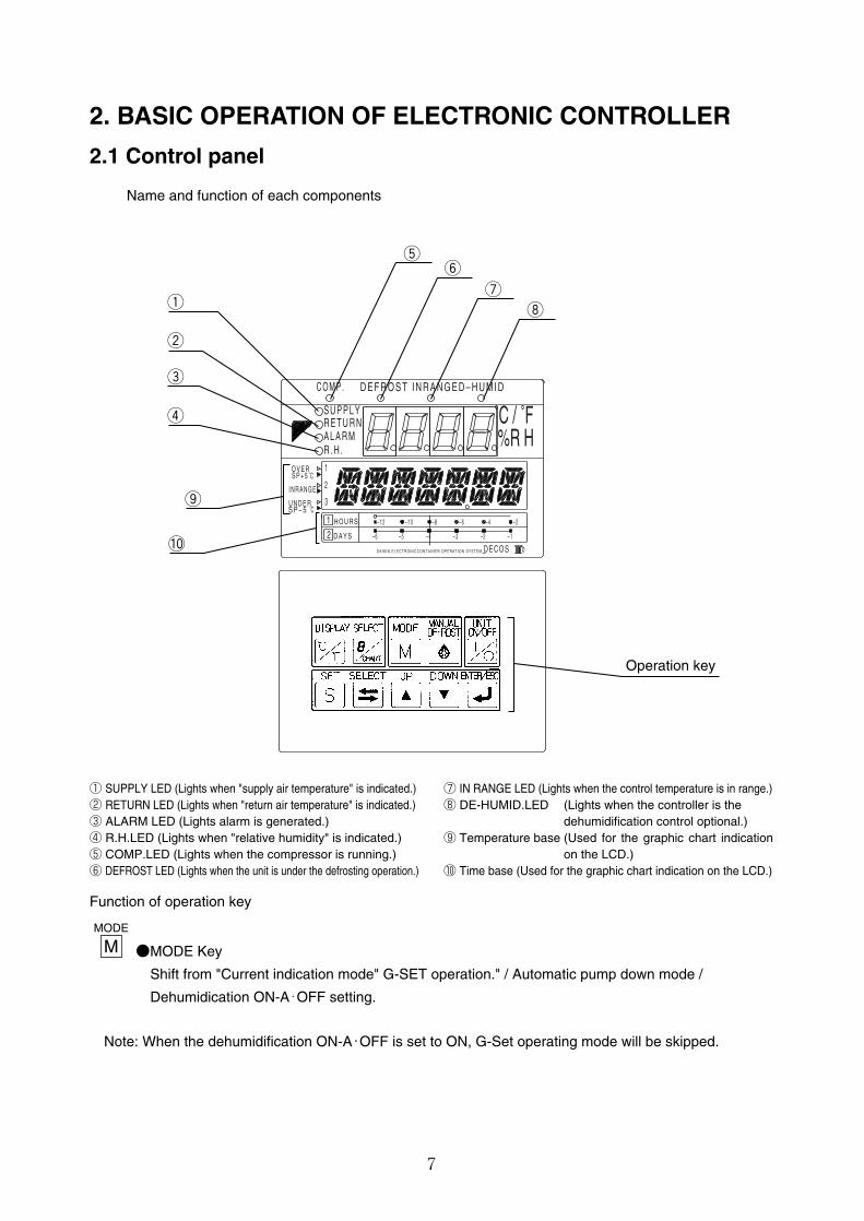
2.1 Control panel
Name and function of each components
q
ty
u
i
w
e
r
o
!0
Operation key
3
1
2
b
– 1 2 – 1 0 – 8 – 6 – 4 – 2
– 2– 3– 4– 5– 6 – 1
S P – 5
O V E R
2
I N R A N G E
H O U R S
D A Y S
1
U N D E R
A L A R MR . H .
S U P P L YR E T U R N ˚C / ˚F
%R H
D E F R O S T I N R A N G E D – H U M I DC O M P .
˚C
˚C
S P + 5
D E C O SD A I K I N E L E C T R O N I C C O N T A I N E R O P E R A T I O N S Y S T E M
① SUPPLY LED (Lights when "supply air temperature" is indicated.)② RETURN LED (Lights when "return air temperature" is indicated.)③ ALARM LED (Lights alarm is generated.)④ R.H.LED (Lights when "relative humidity" is indicated.)⑤ COMP.LED (Lights when the compressor is running.)⑥ DEFROST LED (Lights when the unit is under the defrosting operation.)
⑦ IN RANGE LED (Lights when the control temperature is in range.)⑧ DE-HUMID.LED (Lights when the controller is the
dehumidification control optional.)⑨ Temperature base (Used for the graphic chart indication
on the LCD.)⑩ Time base (Used for the graphic chart indication on the LCD.)
Function of operation key
●MODE Key
Shift from "Current indication mode" G-SET operation." / Automatic pump down mode /
Dehumidication ON-A・OFF setting.
Note: When the dehumidification ON-A・OFF is set to ON, G-Set operating mode will be skipped.
MODE
M
8
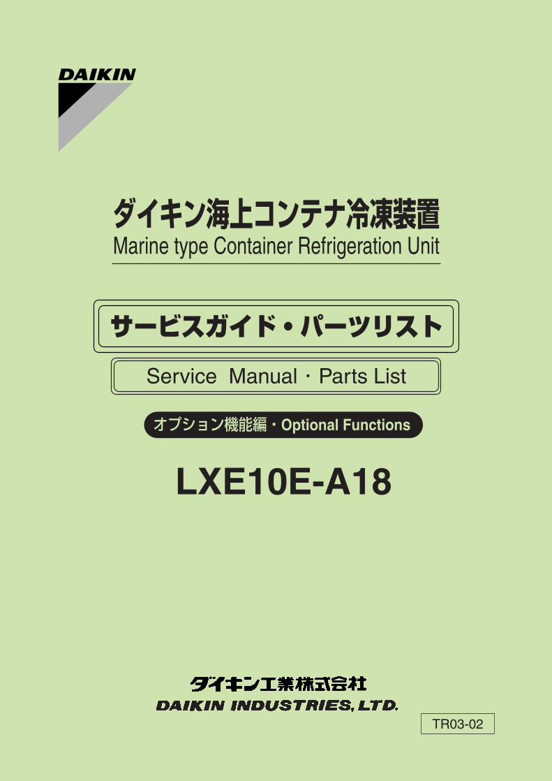
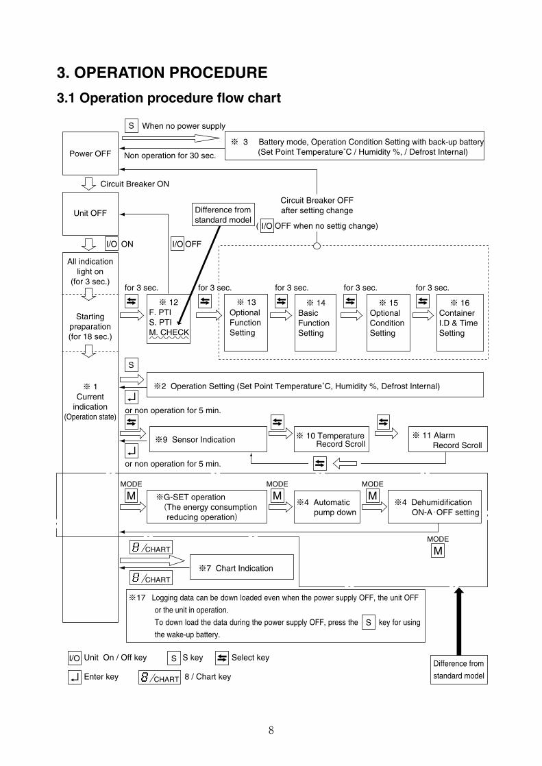
3. OPERATION PROCEDURE
3.1 Operation procedure flow chart
S
S
S
I/O ON I/O OFF
I/O
SI/O Unit On / Off key S key Select key
Enter key 8 / Chart key
CHART
CHART
CHART
Difference from
standard model
Difference fromstandard model
Power OFF
Unit OFF
All indicationlight on
(for 3 sec.)
Startingpreparation(for 18 sec.)
※ 1Current
indication(Operation state)
When no power supply
Non operation for 30 sec.
Circuit Breaker ON
Circuit Breaker OFFafter setting change
( OFF when no settig change)
※ 3 Battery mode, Operation Condition Setting with back-up battery (Set Point Temperature˚C / Humidity %, / Defrost Internal)
for 3 sec. for 3 sec. for 3 sec. for 3 sec.
※ 12 ※ 13
※2 Operation Setting (Set Point Temperature˚C, Humidity %, Defrost Internal)
※9 Sensor Indication
※7 Chart Indication
※ 10 Temperature Record Scroll
※ 11 AlarmRecord Scroll
※ 15※ 14 ※ 16
or non operation for 5 min.
or non operation for 5 min.
※G-SET operation (The energy consumption reducing operation)
※4 Dehumidification ON-A・OFF setting
※4 Automatic pump down
F. PTIS. PTIM. CHECK
※17 Logging data can be down loaded even when the power supply OFF, the unit OFF
or the unit in operation.
To down load the data during the power supply OFF, press the key for using
the wake-up battery.
OptionalFunctionSetting
BasicFunctionSetting
OptionalConditionSetting
ContainerI.D & TimeSetting
for 3 sec.
MODE
MMODE
M
MODE
M
MODE
M
9
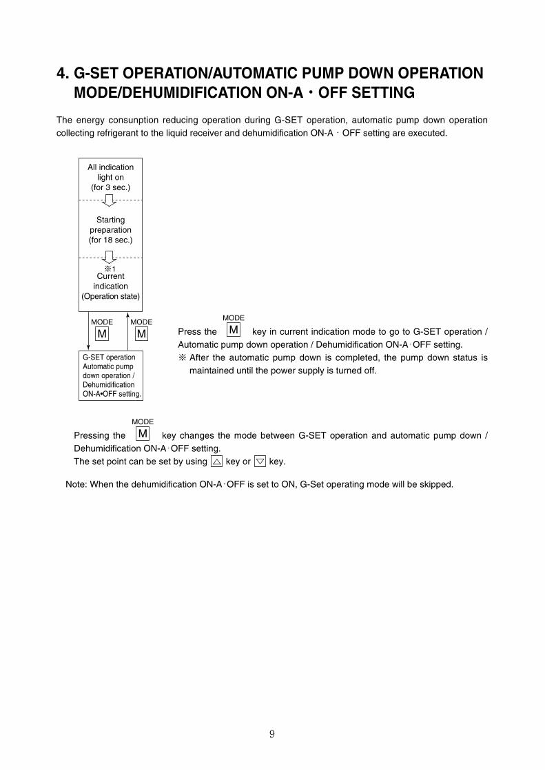
4. G-SET OPERATION/AUTOMATIC PUMP DOWN OPERATIONMODE/DEHUMIDIFICATION ON-A・OFF SETTING
The energy consunption reducing operation during G-SET operation, automatic pump down operationcollecting refrigerant to the liquid receiver and dehumidification ON-A・OFF setting are executed.
Press the key in current indication mode to go to G-SET operation /Automatic pump down operation / Dehumidification ON-A・OFF setting.※ After the automatic pump down is completed, the pump down status is
maintained until the power supply is turned off.
Pressing the key changes the mode between G-SET operation and automatic pump down /Dehumidification ON-A・OFF setting.The set point can be set by using key or key.
Note: When the dehumidification ON-A・OFF is set to ON, G-Set operating mode will be skipped.
MODE
M
MODE
MMODE
M
All indicationlight on
(for 3 sec.)
Startingpreparation(for 18 sec.)
Currentindication
(Operation state)
※1
G-SET operationAutomatic pumpdown operation / DehumidificationON-A•OFF setting.
MODE
M
10
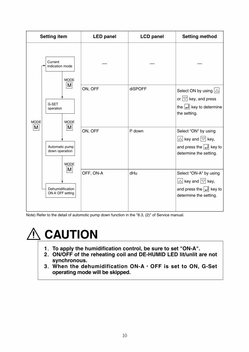
Setting item LED panel LCD panel Setting method
–– –– ––
ON, OFF diSPOFF Select ON by using
or key, and press
the key to determine
the setting.
ON, OFF P down Select "ON" by using
key and key,
and press the key to
determine the setting.
Currentindication mode
G-SEToperation
Automatic pumpdown operation
DehumidificationON-A・OFF setting
MODE
M
MODE
MMODE
M
MODE
M
Note) Refer to the detail of automotic pump down function in the "8.3, (2)" of Service manual.
CAUTION1.To apply the humidification control, be sure to set "ON-A".2.ON/OFF of the reheating coil and DE-HUMID LED lit/unlit are not
synchronous.3.When the dehumidification ON-A・OFF is set to ON, G-Set
operating mode will be skipped.
OFF, ON-A dHu Select "ON-A" by using
key and key,
and press the key to
determine the setting.
11
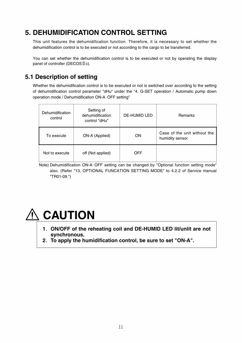
5. DEHUMIDIFICATION CONTROL SETTINGThis unit features the dehumidification function. Therefore, it is necessary to set whether thedehumidification control is to be executed or not according to the cargo to be transferred.
You can set whether the dehumidification control is to be executed or not by operating the displaypanel of controller (DECOSⅢc).
5.1 Description of settingWhether the dehumidification control is to be executed or not is switched over according to the settingof dehumidification control parameter "dHu" under the "4. G-SET operation / Automatic pump downoperation mode / Dehumidification ON-A・OFF setting"
CAUTION1.ON/OFF of the reheating coil and DE-HUMID LED lit/unlit are not
synchronous.2.To apply the humidification control, be sure to set "ON-A".
Dehumidificationcontrol
Setting ofdehumidification
control "dHu"DE-HUMID LED Remarks
To execute ON-A (Applied) ONCase of the unit without thehumidity sensor
Not to execute off (Not applied) OFF
Note) Dehumidification ON-A・OFF setting can be changed by "Optional function setting mode"also. (Refer "13. OPTIONAL FUNCATION SETTING MODE" to 4.2.2 of Service manual"TR01-09.")
12
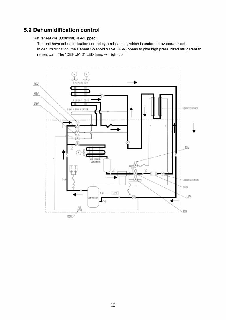
5.2 Dehumidification control※If reheat coil (Optional) is equipped:
The unit have dehumidification control by a reheat coil, which is under the evaporator coil.In dehumidification, the Reheat Solenoid Valve (RSV) opens to give high pressurized refrigerant toreheat coil. The "DEHUMID" LED lamp will light up.
13
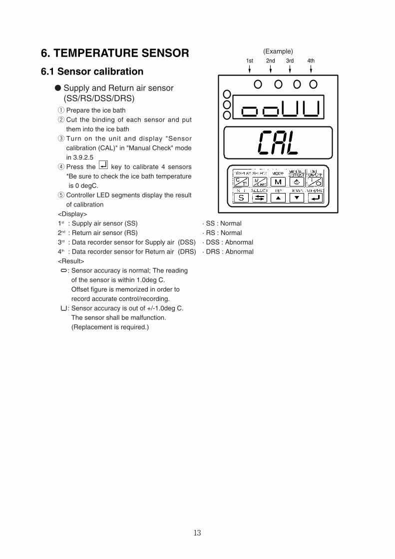
6. TEMPERATURE SENSOR
6.1 Sensor calibration
� Supply and Return air sensor(SS/RS/DSS/DRS)
q Prepare the ice bathw Cut the binding of each sensor and put
them into the ice bathe Turn on the unit and display "Sensor
calibration (CAL)" in "Manual Check" modein 3.9.2.5
r Press the key to calibrate 4 sensors*Be sure to check the ice bath temperatureis 0 degC.
t Controller LED segments display the resultof calibration
<Display>1st : Supply air sensor (SS)2nd : Return air sensor (RS)3rd : Data recorder sensor for Supply air4th : Data recorder sensor for Return air<Result>
: Sensor accuracy is normal; The readingof the sensor is within 1.0deg C.Offset figure is memorized in order torecord accurate control/recording.
: Sensor accuracy is out of +/-1.0deg C.The sensor shall be malfunction.(Replacement is required.)
1st 2nd 3rd 4th
(Example)
· SS : Normal· RS : Normal
(DSS) · DSS : Abnormal(DRS) · DRS : Abnormal
14
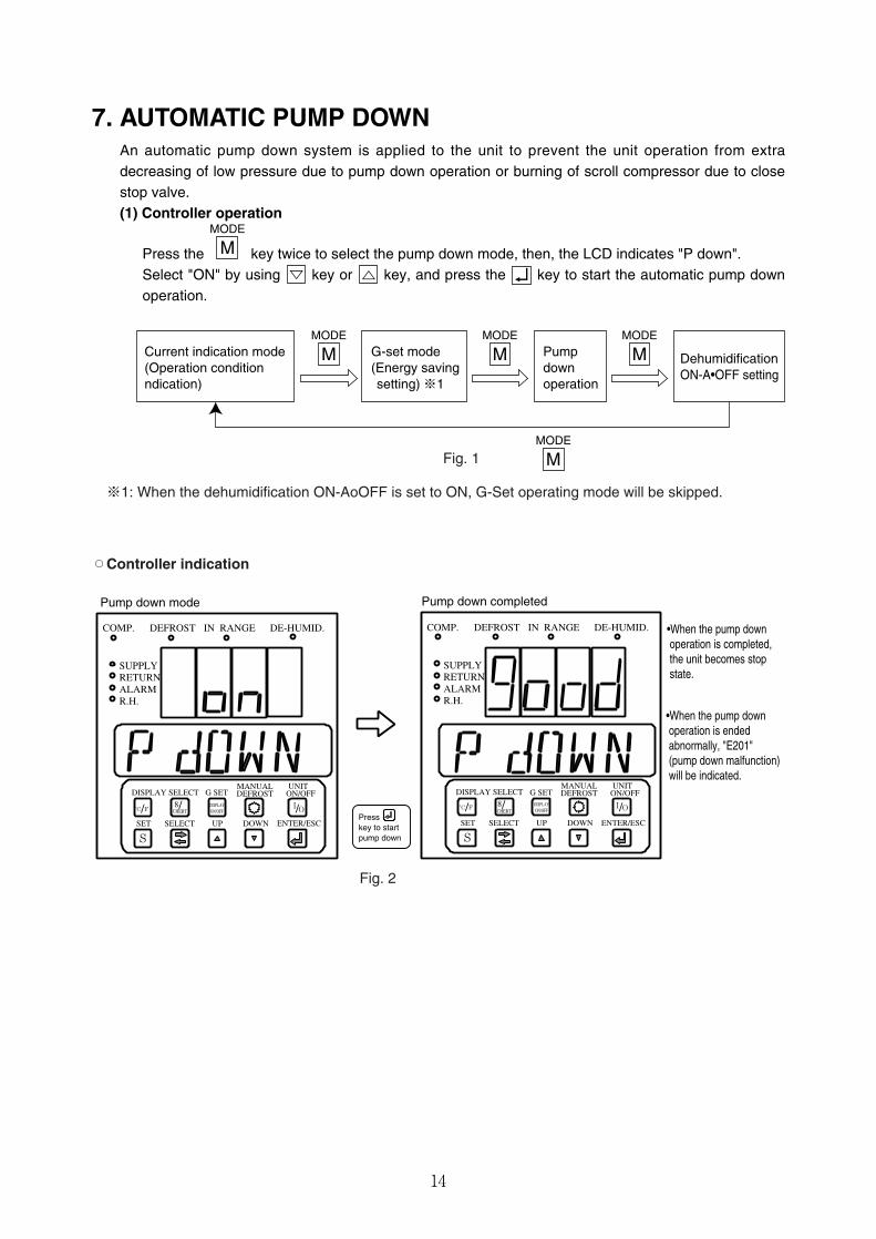
7. AUTOMATIC PUMP DOWNAn automatic pump down system is applied to the unit to prevent the unit operation from extradecreasing of low pressure due to pump down operation or burning of scroll compressor due to closestop valve.(1) Controller operation
Press the key twice to select the pump down mode, then, the LCD indicates "P down".Select "ON" by using key or key, and press the key to start the automatic pump downoperation.
MODE
M
™Controller indication
COMP. DEFROST IN RANGE DE-HUMID.
SUPPLYRETURNALARMR.H.
DISPLAY SELECT G SET G SETMANUAL UNIT
UPSELECTSET
DEFROST ON/OFF
˚C F8
CHERT/ / I/O
SDOWN ENTER/ESC
Pump down mode Pump down completed
COMP. DEFROST IN RANGE DE-HUMID.
SUPPLYRETURNALARMR.H.
DISPLAY SELECTMANUAL UNIT
UPSELECTSET
DEFROST ON/OFF
˚C F 8CHERT/ / I/O
SDOWN ENTER/ESC
DISPLAYON/OFF
DISPLAYON/OFF
•When the pump down operation is ended abnormally, "E201" (pump down malfunction) will be indicated.
•When the pump down operation is completed, the unit becomes stop state.
Presskey to startpump down
Fig. 2
Fig. 1
Current indication mode(Operation condition ndication)
G-set mode(Energy saving setting) ※1
Pumpdownoperation
DehumidificationON-A•OFF setting
MODE
MMODE
MMODE
M
MODE
M
※1: When the dehumidification ON-AoOFF is set to ON, G-Set operating mode will be skipped.
15
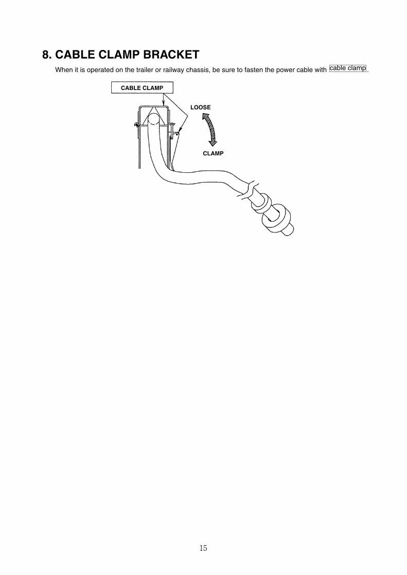
8. CABLE CLAMP BRACKETWhen it is operated on the trailer or railway chassis, be sure to fasten the power cable with .cable clamp
CABLE CLAMP
LOOSE
CLAMP
16
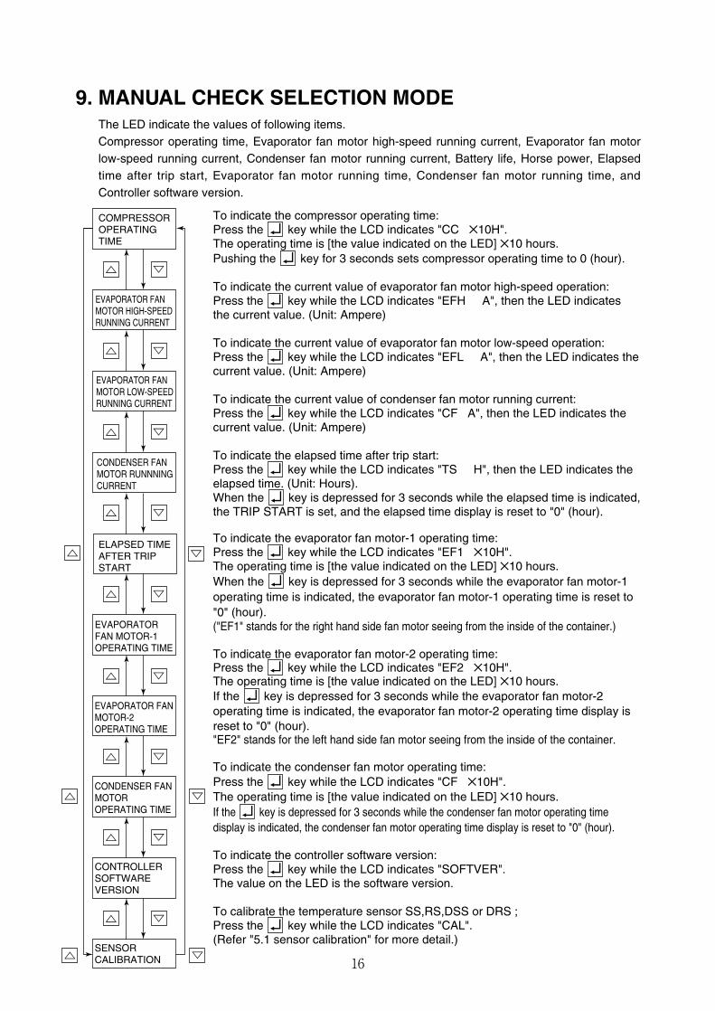
9. MANUAL CHECK SELECTION MODEThe LED indicate the values of following items.Compressor operating time, Evaporator fan motor high-speed running current, Evaporator fan motorlow-speed running current, Condenser fan motor running current, Battery life, Horse power, Elapsedtime after trip start, Evaporator fan motor running time, Condenser fan motor running time, andController software version.
To indicate the compressor operating time:Press the key while the LCD indicates "CC ✕10H".The operating time is [the value indicated on the LED] ✕10 hours.Pushing the key for 3 seconds sets compressor operating time to 0 (hour).
To indicate the current value of evaporator fan motor high-speed operation:Press the key while the LCD indicates "EFH A", then the LED indicatesthe current value. (Unit: Ampere)
To indicate the current value of evaporator fan motor low-speed operation:Press the key while the LCD indicates "EFL A", then the LED indicates thecurrent value. (Unit: Ampere)
To indicate the current value of condenser fan motor running current:Press the key while the LCD indicates "CF A", then the LED indicates thecurrent value. (Unit: Ampere)
To indicate the elapsed time after trip start:Press the key while the LCD indicates "TS H", then the LED indicates theelapsed time. (Unit: Hours).When the key is depressed for 3 seconds while the elapsed time is indicated,the TRIP START is set, and the elapsed time display is reset to "0" (hour).
To indicate the evaporator fan motor-1 operating time:Press the key while the LCD indicates "EF1 ✕10H".The operating time is [the value indicated on the LED] ✕10 hours.When the key is depressed for 3 seconds while the evaporator fan motor-1operating time is indicated, the evaporator fan motor-1 operating time is reset to"0" (hour).("EF1" stands for the right hand side fan motor seeing from the inside of the container.)
To indicate the evaporator fan motor-2 operating time:Press the key while the LCD indicates "EF2 ✕10H".The operating time is [the value indicated on the LED] ✕10 hours.If the key is depressed for 3 seconds while the evaporator fan motor-2operating time is indicated, the evaporator fan motor-2 operating time display isreset to "0" (hour)."EF2" stands for the left hand side fan motor seeing from the inside of the container.
To indicate the condenser fan motor operating time:Press the key while the LCD indicates "CF ✕10H".The operating time is [the value indicated on the LED] ✕10 hours.If the key is depressed for 3 seconds while the condenser fan motor operating timedisplay is indicated, the condenser fan motor operating time display is reset to "0" (hour).
To indicate the controller software version:Press the key while the LCD indicates "SOFTVER".The value on the LED is the software version.
To calibrate the temperature sensor SS,RS,DSS or DRS ;Press the key while the LCD indicates "CAL".(Refer "5.1 sensor calibration" for more detail.)
COMPRESSOROPERATINGTIME
EVAPORATOR FANMOTOR HIGH-SPEEDRUNNING CURRENT
EVAPORATOR FANMOTOR LOW-SPEEDRUNNING CURRENT
EVAPORATORFAN MOTOR-1OPERATING TIME
CONDENSER FANMOTOR RUNNNINGCURRENT
ELAPSED TIMEAFTER TRIPSTART
CONTROLLERSOFTWAREVERSION
EVAPORATOR FANMOTOR-2OPERATING TIME
CONDENSER FANMOTOROPERATING TIME
SENSORCALIBRATION
17
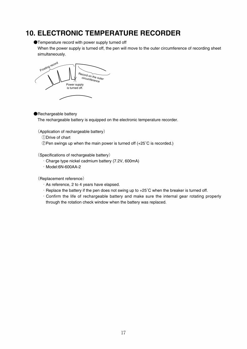
10. ELECTRONIC TEMPERATURE RECORDER●Temperature record with power supply turned off
When the power supply is turned off, the pen will move to the outer circumference of recording sheetsimultaneously.
Record on the outer circumferencePower supplyis turned off.
Frosting record
●Rechargeable batteryThe rechargeable battery is equipped on the electronic temperature recorder.
(Application of rechargeable battery)①Drive of chart②Pen swings up when the main power is turned off (+25˚C is recorded.)
(Specifications of rechargeable battery)・Charge type nickel cadmium battery (7.2V, 600mA)・Model:6N-600AA-2
(Replacement reference)・As reference, 2 to 4 years have elapsed.・Replace the battery if the pen does not swing up to +25˚C when the breaker is turned off.・Confirm the life of rechargeable battery and make sure the internal gear rotating properly
through the rotation check window when the battery was replaced.

18
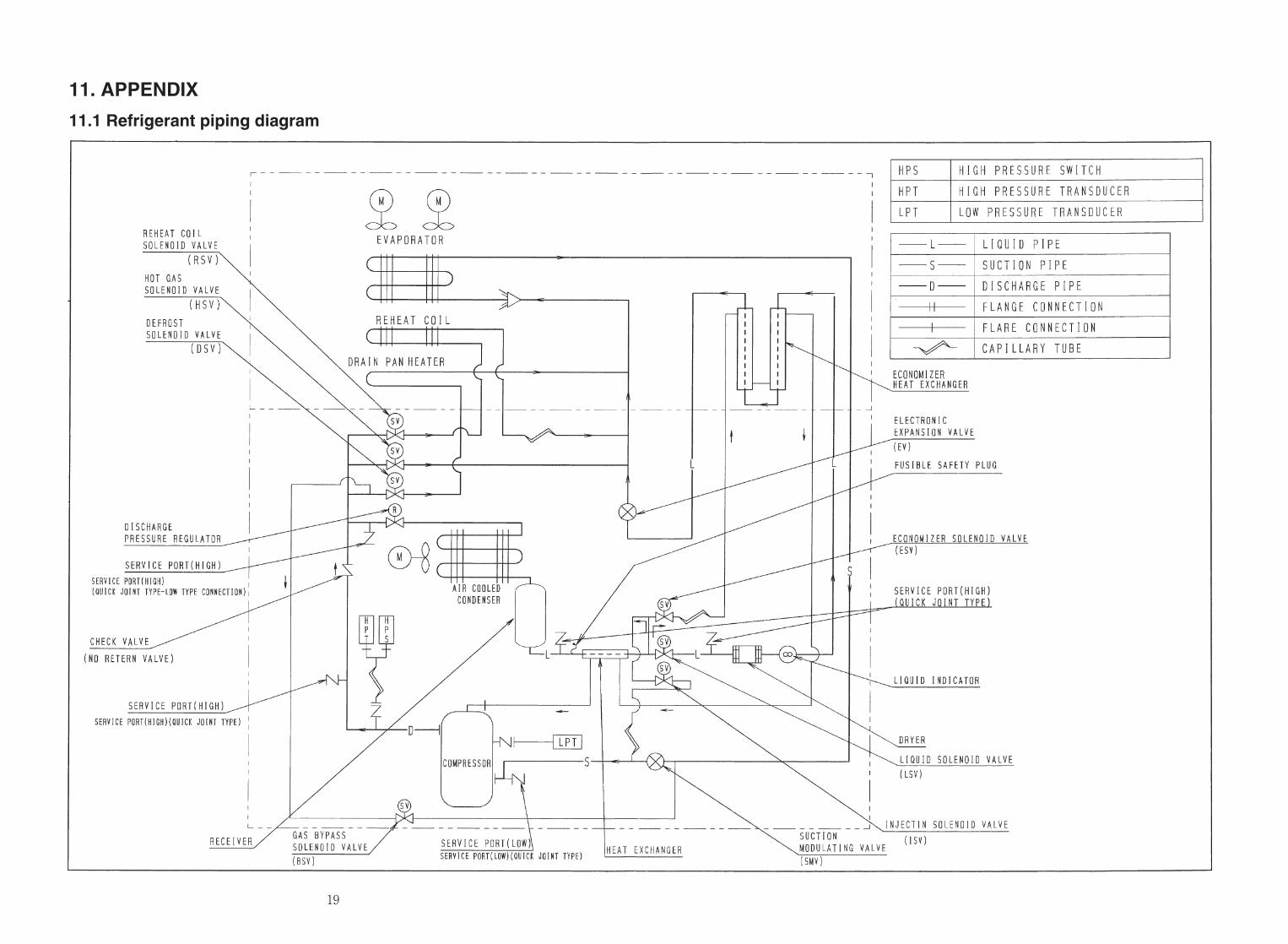
11. APPENDIX
11.1 Refrigerant piping diagram
19
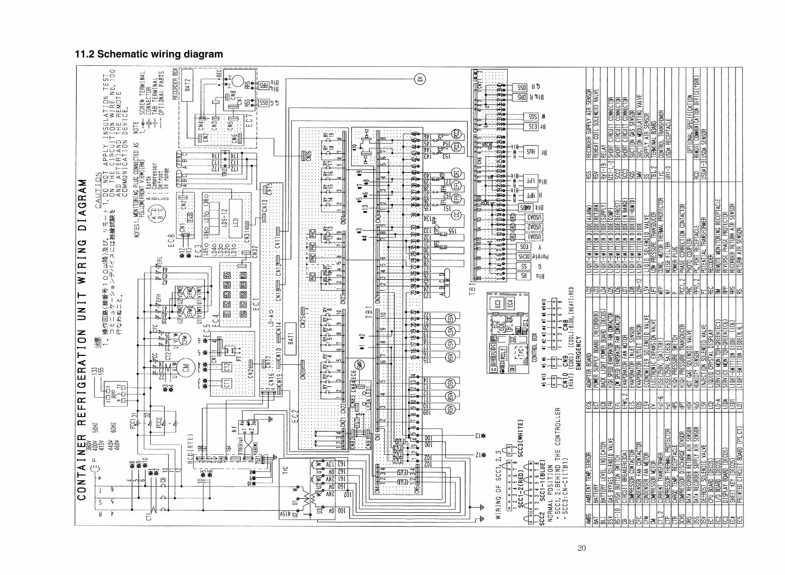
11.2 Schematic wiring diagram
20
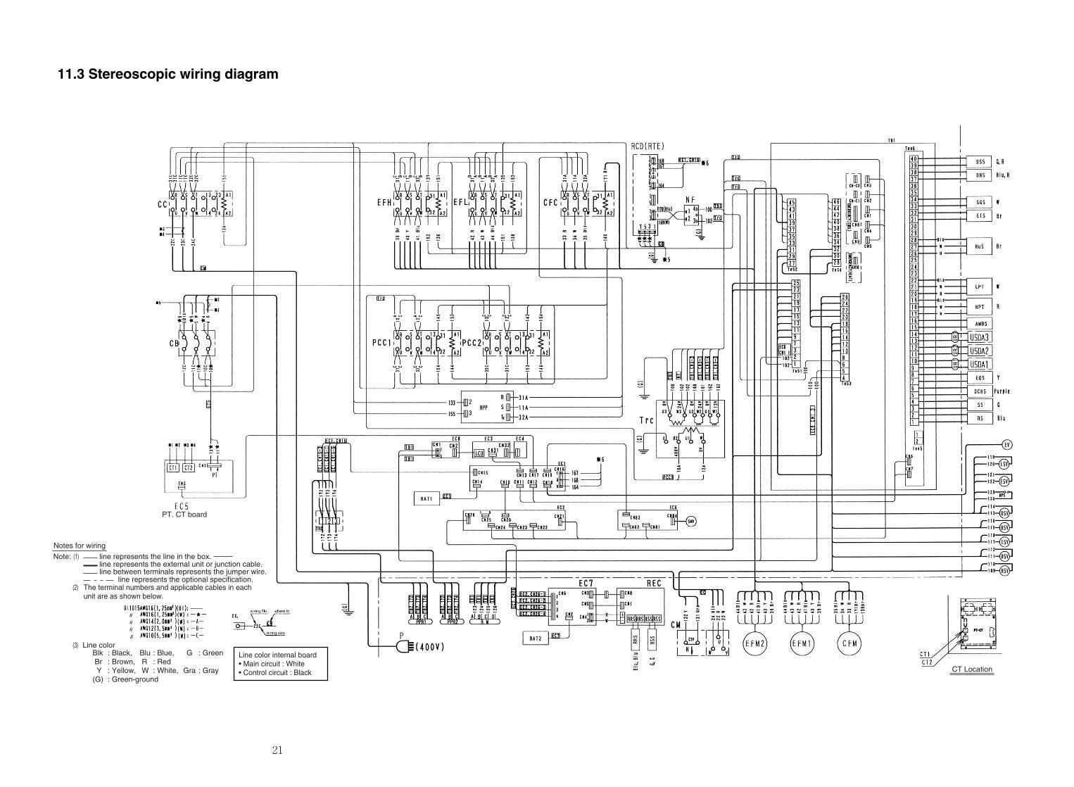
11.3 Stereoscopic wiring diagram
Notes for wiring
line between terminals represents the jumper wire.
line represents the line in the box.(1)Note:
line represents the optional specification.The terminal numbers and applicable cables in eachunit are as shown below.
(2)
line represents the external unit or junction cable.
Blk : Black, Blu : Blue, G : Green Br : Brown, R : Red Y : Yellow, W : White, Gra : Gray(G) : Green-ground
Line color
PT. CT board
(3)
CT Location
Line color internal board• Main circuit : White• Control circuit : Black
21

22
23
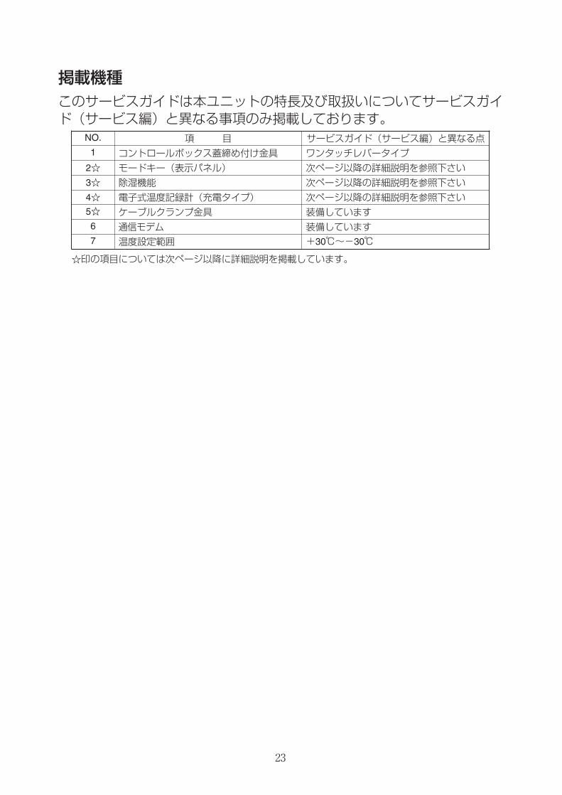
掲載機種このサービスガイドは本ユニットの特長及び取扱いについてサービスガイド(サービス編)と異なる事項のみ掲載しております。
NO. 項 目 サービスガイド(サービス編)と異なる点1 コントロールボックス蓋締め付け金具 ワンタッチレバータイプ
4☆ 電子式温度記録計(充電タイプ) 次ページ以降の詳細説明を参照下さい5☆ ケーブルクランプ金具 装備しています6 通信モデム 装備しています
☆印の項目については次ページ以降に詳細説明を掲載しています。
2☆ モードキー(表示パネル) 次ページ以降の詳細説明を参照下さい
3☆ 除湿機能 次ページ以降の詳細説明を参照下さい
7 温度設定範囲 +30℃~-30℃
24
取扱上の注意・危険…………………………………………………3・警告…………………………………………………4・注意…………………………………………………5
1. 基本操作……………………………………………1-11.1 運転範囲 ………………………………………1-1
☆1.2 各部の名称 ……………………………………1-11.3 運転操作 ………………………………………1-2
1.3.1 運転準備と操作 …………………………1-21.3.2 運転中の点検 ……………………………1-51.3.3 停止後の処置 ……………………………1-5
☆1.4 電子式コントローラの基本操作 ……………1-61.4.1 コントロールパネル ………………………1-6
1.4.2 操作方法 …………………………………1-81.4.2.1 カレント(運転状態)表示モード …1-81.4.2.2 運転設定モード ……………………1-91.4.2.3 電池モード …………………………1-10
1.4.2.4 ジーセット運転とマニュアルデフロスト運転 …1-11
1.4.3 温度設定と運転モード…………………1-112.製品データ…………………………………………2-1
2.1 主仕様 …………………………………………2-12.2 部品名称 ………………………………………2-2
2.2.1 庫外側 ……………………………………2-22.2.2 庫内側 ……………………………………2-32.2.3 コントロールボックス …………………2-4
2.3 機能部品・保護装置の設定値 ………………2-52.4 運転圧力と電流値 ……………………………2-6
3.運転モードと制御…………………………………3-13.1 フローズン運転 ………………………………3-23.2 チルド、パーシャルフローズン運転 ………3-43.3 デフロスト運転 ………………………………3-63.4 共通制御 ………………………………………3-9
4.電子式コントローラ………………………………4-14.1 機能 ……………………………………………4-14.2 操作方法 ………………………………………4-3
☆ 4.2.1 操作方法フローチャート ………………4-34.2.2 各表示モード操作方法 …………………4-7
4.3 アラーム表示とバックアップ機能…………4-294.3.1 アラーム一覧表…………………………4-294.3.2 PTI(使用前点検)中のアラーム一覧 …4-304.3.3 センサ異常時のバックアップ運転……4-31
4.4 電池……………………………………………4-334.4.1 電池の仕様………………………………4-334.4.2 電池の交換時期…………………………4-334.4.3 電池の交換方法…………………………4-33
4.5 パソコンとの情報交換………………………4-344.5.1 データロギング…………………………4-354.5.2 パソコンソフトの構成…………………4-36
4.6 コントローラの点検方法……………………4-384.7 コントローラの交換および初期設定………4-39
4.7.1 コントローラの交換……………………4-394.7.2 コントローラの初期設定………………4-41
4.8 オプション……………………………………4-415. PTI(使用前点検)と定期点検 ……………………5-1
5.1 点検項目 ………………………………………5-25.2 自動PTI…………………………………………5-5
5.2.1 S.PTI………………………………………5-65.2.2 F.PTI ………………………………………5-75.2.3 PTI(使用前点検)中のアラーム一覧……5-85.2.4 M.CHECK…………………………………5-9
目 次
6.チャートレス機能…………………………………6-16.1 チャート表示機能 ……………………………6-16.2 温度記録スクロール表示機能 ………………6-36.3 アラーム記録スクロール表示 ………………6-56.4 チャートレスコード …………………………6-6
6.4.1 Pコード……………………………………6-66.4.2 Hコード……………………………………6-66.4.3 dコード……………………………………6-66.4.4 チャートレスコード一覧 ………………6-7
7.主要機器とメンテナンス…………………………7-17.1 冷媒系統関連機器 ……………………………7-1
7.1.1 スクロール圧縮機 ………………………7-17.1.2 空冷凝縮器、蒸発器 ……………………7-37.1.3 可溶栓 ……………………………………7-37.1.4 ドライヤ …………………………………7-47.1.5 リキッド/モイスチャーインジケータ…7-47.1.6 電子膨張弁 ………………………………7-57.1.7 吸入比例弁 ………………………………7-67.1.8 電磁弁 ……………………………………7-77.1.9 吐出圧力調整弁 …………………………7-87.1.10 逆止弁……………………………………7-97.1.11 高圧圧力開閉器(HPS)………………7-97.1.12 低圧圧力センサ(LPT)………………7-107.1.13 高圧圧力センサ(HPT)………………7-10
7.2 ファンおよび電動機…………………………7-117.3 PT/CTボード…………………………………7-12
8.サービスの方法……………………………………8-18.1 冷媒の回収 ……………………………………8-18.2 ゲージマニホールドの取付け、取外し ……8-1
☆8.3 自動ポンプダウン ……………………………8-38.4 冷媒の交換および充填 ………………………8-58.5 真空乾燥 ………………………………………8-7
9.オプション…………………………………………9-19.1 電子式温度記録計 ……………………………9-19.2 USDAレセプタクル及びセンサ ……………9-39.3 TransFRESH …………………………………9-5
10.故障診断…………………………………………10-110.1 冷媒システム・電気 ………………………10-110.2 電子式コントローラ ………………………10-410.3 自動PTIのトラブルシューティング ……10-810.4 記録紙による診断 ………………………10-1010.5 緊急運転の方法 …………………………10-13
10.5.1 コントローラの緊急運転……………10-1310.5.2 コントローラの短絡運転……………10-1410.5.3 電子膨張弁の緊急運転………………10-1610.5.4 吸入比例弁の緊急運転方法…………10-1710.5.5 吹出センサ・吸込センサ緊急運転…10-18
11. 付図………………………………………………11-111.1 ボルトの標準締付トルク …………………11-111.2 フレヤナットの標準締付トルク …………11-111.3 モータコイル及び電磁弁コイルの抵抗値 …11-111.4 HFC134a、温度一蒸気圧特性表…………11-211.5 温度換算表と温度センサ(SS/RS/DSS/DRS/RSS/RRS/EIS/EOS/SGS/AMBS)特性表 ……………………………11-3
11.6 温度換算表と温度センサ(DCHS)特性表…11-411.7 高圧圧力センサ特性表 ……………………11-411.8 低圧圧力センサ特性表 ……………………11-4
☆11.9 配管系統図 …………………………………11-511.10 電気配線 表示灯とモニタリング回路 …11-6
☆11.11 シーケンス…………………………………11-711.12 実体配線図 ………………………………11-8
※本編のサービスマニュアル(TR01-08/TR01-09)と異なる項目(☆印)
☆
25
目 次1. 部品名称……………………………………………………………………27
1.1 庫外側…………………………………………………………………27
1.2 庫内側…………………………………………………………………28
2. 電子式コントローラの基本操作…………………………………………29
2.1 コントロールパネル…………………………………………………29
3. 操作方法……………………………………………………………………30
3.1 操作方法フローチャート……………………………………………30
4. ジーセット運転/自動ポンプダウン運転/除湿ON-A・OFF設定 …31
5. 除湿制御……………………………………………………………………33
5.1 設定内容………………………………………………………………33
5.2 除湿制御………………………………………………………………34
6. 温度センサー………………………………………………………………35
6.1 センサーキャリブレーション………………………………………35
7. 自動ポンプダウン…………………………………………………………36
8. ケーブルクランプ金具……………………………………………………37
9. マニュアルチェック選択モード…………………………………………38
10. 電子式温度記録計…………………………………………………………39
11. 付図…………………………………………………………………………41
11.1 配管系統図 …………………………………………………………41
11.2 シーンケース ………………………………………………………42
11.3 実体配線図 …………………………………………………………43
26
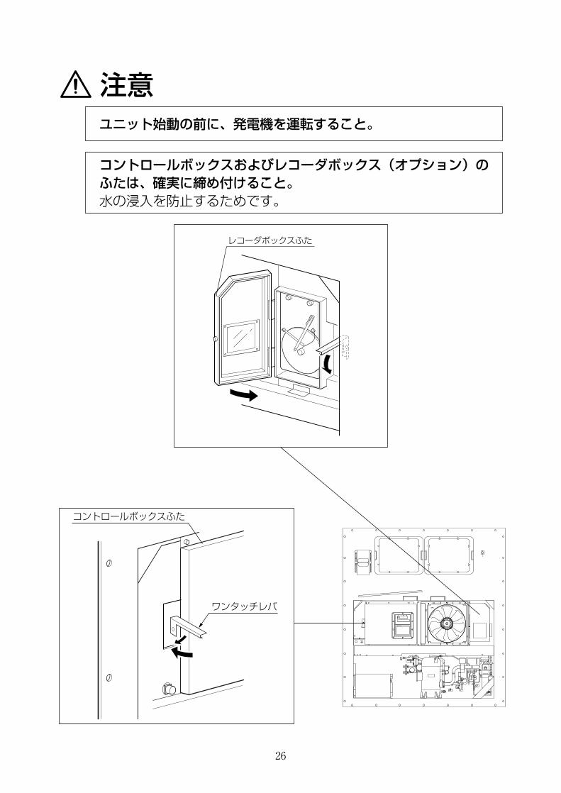
注意
レコーダボックスふた
ワンタッチレバ
コントロールボックスふた
ユニット始動の前に、発電機を運転すること。
コントロールボックスおよびレコーダボックス(オプション)のふたは、確実に締め付けること。水の浸入を防止するためです。
27
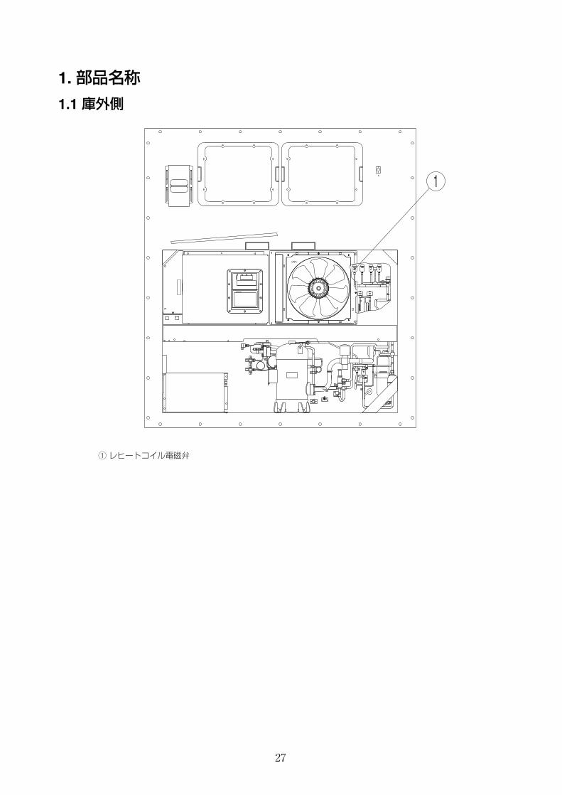
1. 部品名称
1.1 庫外側
q レヒートコイル電磁弁
1
28
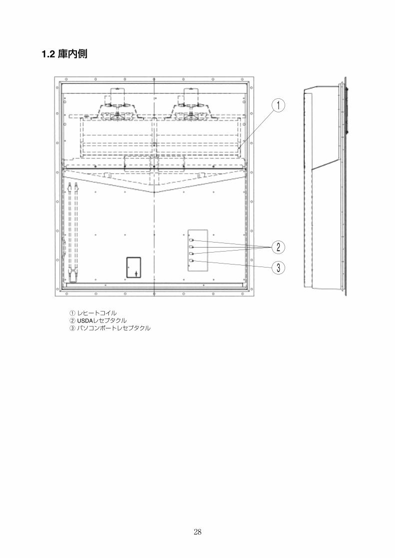
1.2 庫内側
1
3
2
q レヒートコイルw USDAレセプタクルe パソコンポートレセプタクル
29
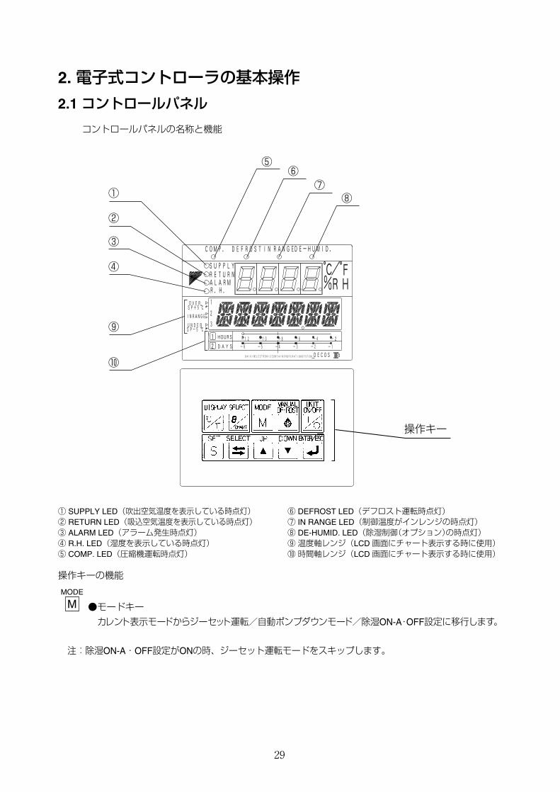
2. 電子式コントローラの基本操作
2.1 コントロールパネル
コントロールパネルの名称と機能
①
⑤ ⑥
⑦ ⑧
②
③
④
⑨
⑩
操作キー
3
1
2
ALARM RH
DE-HUMID.
b
-12
C
F
SP-5
OVER
HOURS
-1 -4 -6 -2 -3 -5
IN
2 SYSTEM
R.H.
DEFROST
C
C
-4
RANGE
%
-2
IN
OPERATION
RANGE
SUPPLY
DAIKIN CONTAINER
DAYS
1
° °
-10
UNDER
RETURN
-6 -8
/ COMP.
SP+5
DECOS ELECTRONIC
① SUPPLY LED(吹出空気温度を表示している時点灯)② RETURN LED(吸込空気温度を表示している時点灯)③ ALARM LED(アラーム発生時点灯)④ R.H. LED(湿度を表示している時点灯)⑤ COMP. LED(圧縮機運転時点灯)
⑥ DEFROST LED(デフロスト運転時点灯)⑦ IN RANGE LED(制御温度がインレンジの時点灯)⑧ DE-HUMID. LED(除湿制御(オプション)の時点灯)⑨温度軸レンジ(LCD 画面にチャート表示する時に使用)⑩時間軸レンジ(LCD 画面にチャート表示する時に使用)
操作キーの機能
●モードキー
カレント表示モードからジーセット運転/自動ポンプダウンモード/除湿ON-A・OFF設定に移行します。
注:除湿ON-A・OFF設定がONの時、ジーセット運転モードをスキップします。
MODE
M
30
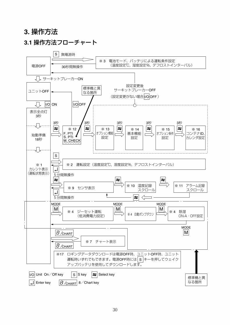
3. 操作方法
3.1 操作方法フローチャート
S
S
S
I/O ON I/O OFF
I/O OFF
SI/O Unit On/Off key S key Select key
Enter key 8/Chart key
CHART
CHART
CHART
標準機と異 なる箇所
電源OFF
ユニットOFF
表示全点灯3秒
始動準備18秒
※ 1カレント表示(運転状態表示)
無電源時
30秒間無操作
サーキットブレーカーON
設定変更後サーキットブレーカーOFF
(設定変更がない場合 )
※ 3 電池モード、バッテリによる運転条件設定 (温度設定℃, 湿度設定%, デフロストインターバル)
3秒 3秒 3秒 3秒 3秒
※ 12 ※ 13オプション機能設定
※ 2 運転設定(温度設定℃, 湿度設定%, デフロストインターバル)
※ 9 センサ表示
※ 7 チャート表示
※ 10 温度記録スクロール
※ 11 アラーム記録スクロール
※ 15オプション条件設定
※ 14基本機能設定
※ 16コンテナID,カレンダ設定
5分間無操作
5分間無操作
F. PTIS. PTIM. CHECK
※17 ロギングデータダウンロードは電源OFF時、ユニットOFF時、ユニット運転時いずれでもできます。電源OFF時には キーを押してウェイクアップバッテリを使用してダウンロードします。
標準機と異なる箇所
※ 4 ジーセット運転 (低消費電力設定)
※ 4 除湿 ON-A・OFF設定 ※ 4 自動ポンプダウン
MODE
MMODE
M
MODE
M
MODE
M
31
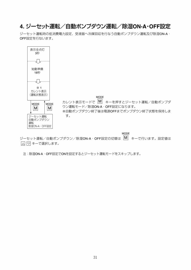
4.ジーセット運転/自動ポンプダウン運転/除湿ON-A・OFF設定ジーセット運転時の低消費電力設定、受液器へ冷媒回収を行なう自動ポンプダウン運転及び除湿ON-A・OFF設定を行ないます。
カレント表示モードで キーを押すとジーセット運転/自動ポンプダウン運転モード/除湿ON-A・OFF設定になります。※自動ポンプダウン終了後は電源OFFまでポンプダウン終了状態を保持します。
ジーセット運転/自動ポンプダウン/除湿ON-A・OFF設定の切替は キーで行います。設定値は
キーで選択します。
注:除湿ON-A・OFF設定でONを設定するとジーセット運転モードをスキップします。
MODE
M
MODE
M
ジーセット運転 自動ポンプダウン 運転 除湿ON-A・OFF設定
表示全点灯3秒
始動準備18秒
※ 1カレント表示(運転状態表示)
MODE
MMODE
M
32
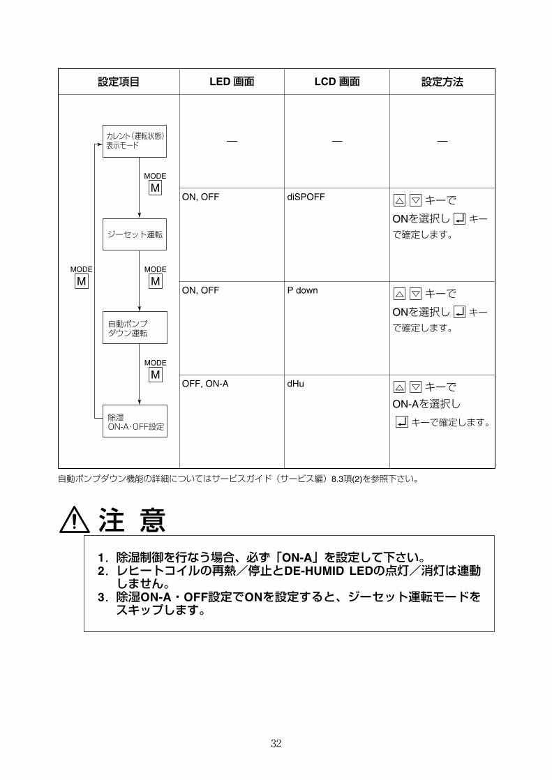
設定項目 LED 画面 LCD 画面 設定方法
–– –– ––
ON, OFF diSPOFF キーで
ONを選択し キー
で確定します。
ON, OFF P down キーで
ONを選択し キー
で確定します。
カレント(運転状態) 表示モード
ジーセット運転
自動ポンプ ダウン運転
除湿 ON-A・OFF設定
MODE
M
MODE
MMODE
M
MODE
M
自動ポンプダウン機能の詳細についてはサービスガイド(サービス編)8.3項(2)を参照下さい。
注 意1.除湿制御を行なう場合、必ず「ON-A」を設定して下さい。2.レヒートコイルの再熱/停止とDE-HUMID LEDの点灯/消灯は連動しません。
3.除湿ON-A・OFF設定でONを設定すると、ジーセット運転モードをスキップします。
OFF, ON-A dHu キーで
ON-Aを選択し
キーで確定します。
33
5. 除湿制御本ユニットは除湿制御機能を装備しているため、輸送するカーゴにより、除湿制御有無の設定を行う必要があります。
コントローラ(DECOSⅢc)の表示パネル操作により除湿制御有無の設定を行うことが出来ます。
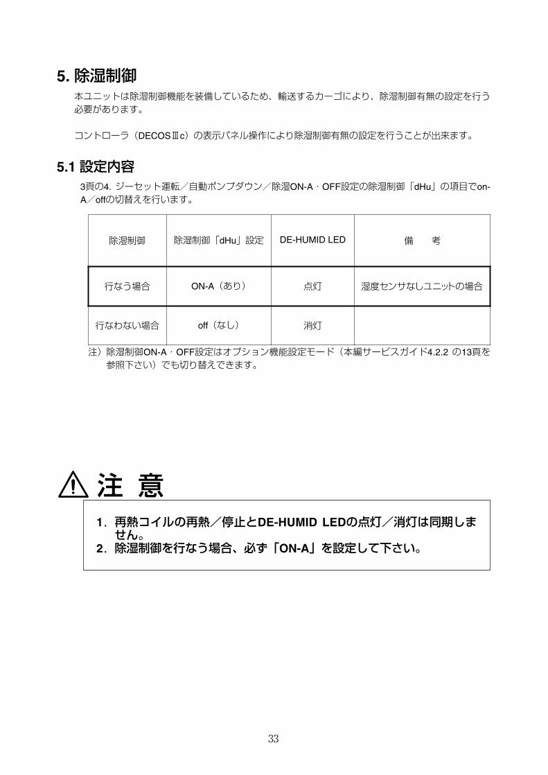
5.1 設定内容3頁の4. ジーセット運転/自動ポンプダウン/除湿ON-A・OFF設定の除湿制御「dHu」の項目でon-A/offの切替えを行います。
注 意1.再熱コイルの再熱/停止とDE-HUMID LEDの点灯/消灯は同期しません。
2.除湿制御を行なう場合、必ず「ON-A」を設定して下さい。
除湿制御 除湿制御「dHu」設定 DE-HUMID LED 備 考
行なう場合 ON-A(あり) 点灯 湿度センサなしユニットの場合
行なわない場合 off(なし) 消灯
注)除湿制御ON-A・OFF設定はオプション機能設定モード(本編サービスガイド4.2.2 の13頁を参照下さい)でも切り替えできます。
34
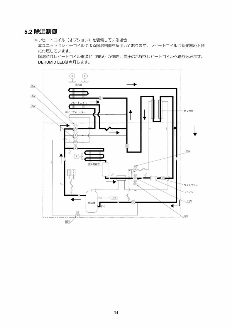
5.2 除湿制御※レヒートコイル(オプション)を装備している場合:本ユニットはレヒーコイルによる除湿制御を採用しております。レヒートコイルは蒸発器の下側に付属しています。除湿時はレヒートコイル電磁弁(RSV)が開き、高圧の冷媒をレヒートコイルへ送り込みます。DEHUMID LEDは点灯します。
蒸発器
レヒートコイル
ドレンパンヒーター
空冷凝縮器
圧縮機
ドライヤ
サイトグラス
熱交換器
35
6. 温度センサー
6.1 センサーキャリブレーション
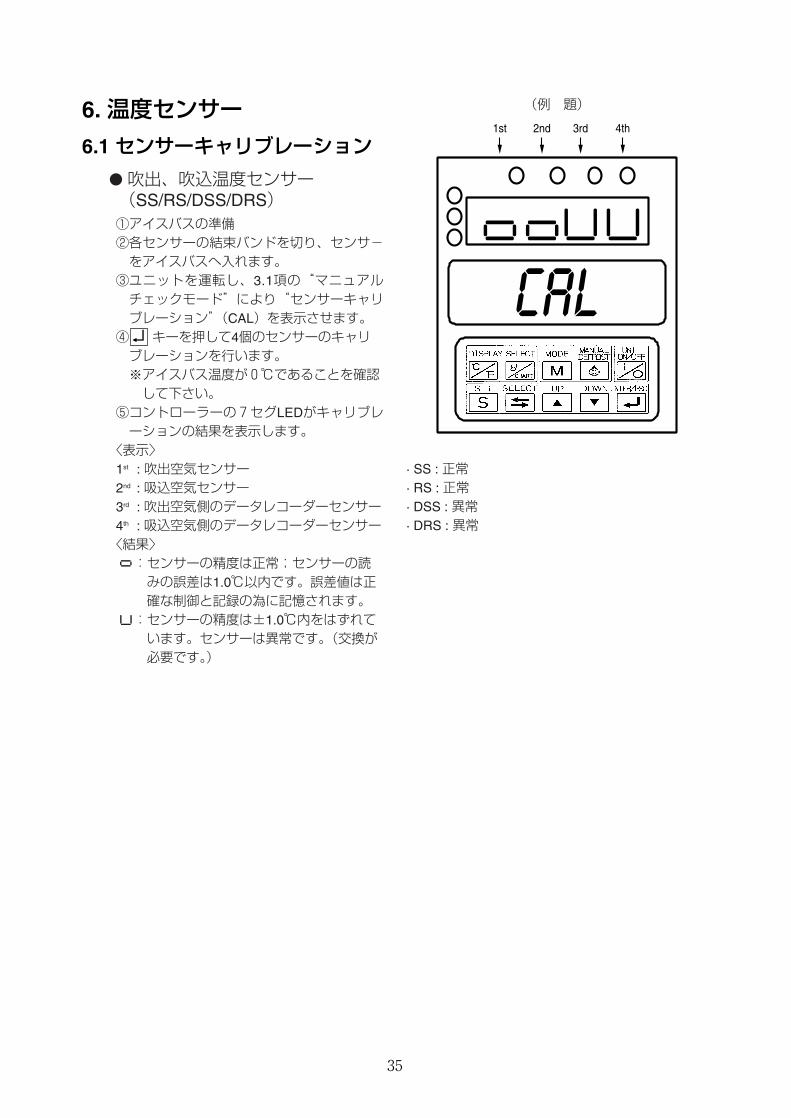
�吹出、吹込温度センサー(SS/RS/DSS/DRS)①アイスバスの準備②各センサーの結束バンドを切り、センサ-をアイスバスへ入れます。③ユニットを運転し、3.1項の“マニュアルチェックモード”により“センサーキャリブレーション”(CAL)を表示させます。④ キーを押して4個のセンサーのキャリブレーションを行います。※アイスバス温度が0℃であることを確認して下さい。
⑤コントローラーの7セグLEDがキャリブレーションの結果を表示します。
〈表示〉1st : 吹出空気センサー2nd : 吸込空気センサー3rd : 吹出空気側のデータレコーダーセンサー4th : 吸込空気側のデータレコーダーセンサー〈結果〉:センサーの精度は正常;センサーの読みの誤差は1.0℃以内です。誤差値は正確な制御と記録の為に記憶されます。:センサーの精度は±1.0℃内をはずれています。センサーは異常です。(交換が必要です。)
1st 2nd 3rd 4th
(例 題)
· SS : 正常· RS : 正常· DSS : 異常· DRS : 異常
36
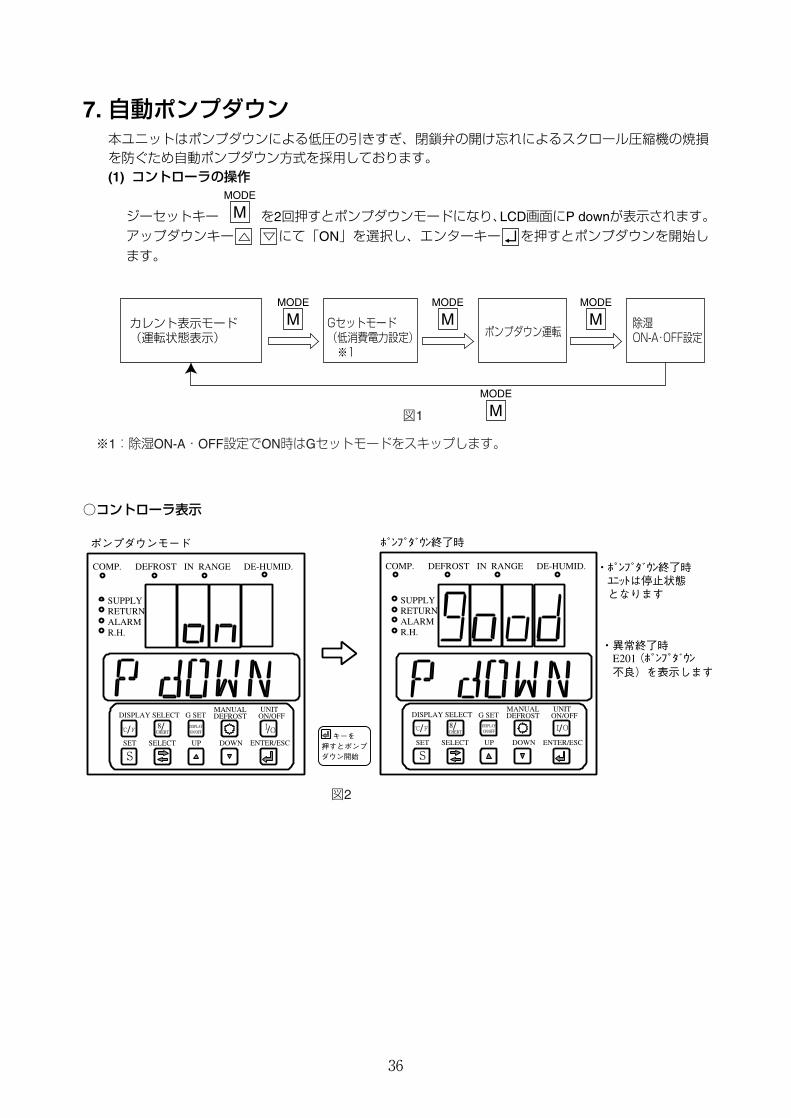
7. 自動ポンプダウン本ユニットはポンプダウンによる低圧の引きすぎ、閉鎖弁の開け忘れによるスクロール圧縮機の焼損を防ぐため自動ポンプダウン方式を採用しております。(1) コントローラの操作
ジーセットキー を2回押すとポンプダウンモードになり、LCD画面にP downが表示されます。アップダウンキー にて「ON」を選択し、エンターキー を押すとポンプダウンを開始します。
MODE
M
○コントローラ表示
COMP. DEFROST IN RANGE DE-HUMID.
SUPPLYRETURNALARMR.H.
DISPLAY SELECTMANUAL UNIT
UPSELECTSET
DEFROST ON/OFF
℃ F 8
CHERT/ / I /O
S DOWN ENTER/ESC
ポンプダウンモード ポンプダウン終了時
COMP. DEFROST IN RANGE DE-HUMID.
SUPPLYRETURNALARMR.H.
DISPLAY SELECTMANUAL UNIT
UPSELECTSET
DEFROST ON/OFF
℃ F 8CHERT/ / I /O
S DOWN ENTER/ESC
DISPLAYON/OFF
DISPLAYON/OFF
・異常終了時 E201(ポンプダウン 不良)を表示します
・ポンプダウン終了時 ユニットは停止状態 となります
キーを 押すとポンプダウン開始
G SET G SET
図2
図1
カレント表示モード (運転状態表示)
Gセットモード (低消費電力設定) ※1
ポンプダウン運転 除湿 ON-A・OFF設定
MODE
MMODE
M
MODE
M
MODE
M
※1:除湿ON-A・OFF設定でON時はGセットモードをスキップします。
37
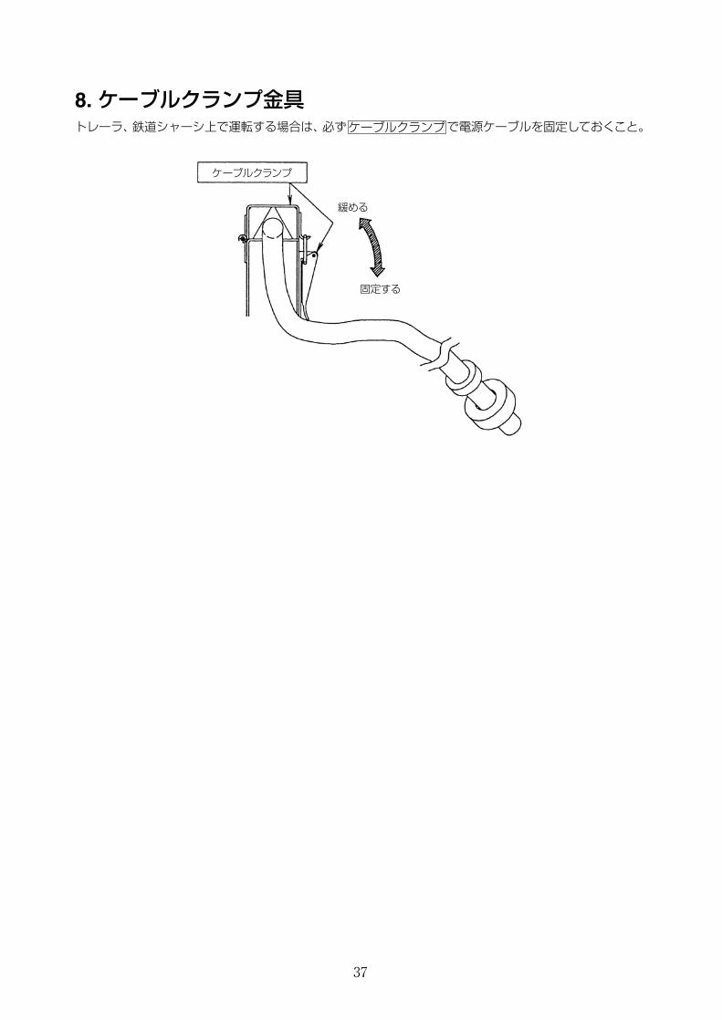
8. ケーブルクランプ金具トレーラ、鉄道シャーシ上で運転する場合は、必ず で電源ケーブルを固定しておくこと。ケーブルクランプ
ケーブルクランプ
緩める
固定する
38
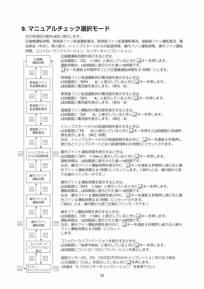
9. マニュアルチェック選択モード次の各項目の値をLEDに表示します。圧縮機運転時間、蒸発器ファン高速運転電流、蒸発器ファン低速運転電流、凝縮器ファン運転電流、電池寿命(年月)、馬力表示、トリップスタートからの経過時間、庫内ファン運転時間、庫外ファン運転時間、コントローラソフトバージョン、センサーキャリブレーション。
圧縮機運転時間を表示するときは、LCD画面に「CC ×10H」と表示しているときに キーを押します。運転時間は、LED画面に表示された値×10時間です。キーを連続 3 秒間押すことで圧縮機運転時間を 0(時間)にします。
蒸発器ファン高速運転時の電流値を表示するときは、LCD画面に「EFH A」と表示しているときに キーを押します。LED画面に電流値を表示します。(単位:A)
蒸発器ファン低速運転時の電流値を表示するときは、LCD画面に「EFL A」と表示しているときに キーを押します。LED画面に電流値を表示します。(単位:A)
凝縮器ファン運転時の電流値を表示するときは、LCD画面に「CF A」と表示しているときに キーを押します。LED画面に電流値を表示します。(単位:A)
トリップスタートからの経過時間を表示するときは、LCD画面に「TS H」と表示しているときに キーを押すとLED画面に経過時間を表示します。(単位:時間)なお、トリップスタートからの経過時間を表示中に、 キーを連続 3 秒間押し続けるとトリップスタートとなり経過時間は 0(時間)にリセットされます。
庫内ファン 1 運転時間を表示するときは、LCD画面に「EF1 ×10H」と表示しているときに キーを押します。運転時間は、LED画面に表示された値×10時間です。なお、庫内ファン 1 運転時間を表示中に、 キーを連続 3 秒間押し続けると庫内ファン 1 運転時間は 0(時間)にリセットします。(「EF1」とは、庫内側から見て右側のファンモータです。)
庫内ファン 2 運転時間を表示するときは、LCD画面に「EF2 ×10H」と表示しているときに キーを押します。運転時間は、LED画面に表示された値×10時間です。なお、庫内ファン 2 運転時間を表示中に、 キーを連続 3 秒間押し続けると庫内ファン 2 運転時間は 0(時間)にリセットされます。(「EF2」とは、庫内側から見て左側のファンモータです。)
庫外ファン運転時間を表示するときは、LCD画面に「CF ×10H」と表示しているときに キーを押します。運転時間は、LED画面に表示された値×10時間です。なお、庫外ファン運転時間を表示中に、 キーを連続 3 秒間押し続けると庫外ファン運転時間は 0(時間)にリセットします。
コントローラソフトバージョンを表示するときは、LCD画面に「SOFTVER」と表示しているときに キーを押します。LED画面にコントローラのソフトバージョンを表示します。
温度センサーSS、RS、DSS及びDRSのキャリブレーションを行なう時はLCD画面に「CAL」を表示しているときに を押します。(詳細は“5.1のセンサーキャリブレーション”を参照下さい)
圧縮機 運転時間
蒸発器ファン 高速運転電流
蒸発器ファン 低速運転電流
庫内ファン 1 運転時間
凝縮器ファン 運転電流
トリップスタート からの経過時間
庫内ファン 2 運転時間
庫外ファン 運転時間
コントローラ ソフトバージョン
表示
センサー キャリブレーション
39
外周記録
電源OFF
フロスト記録
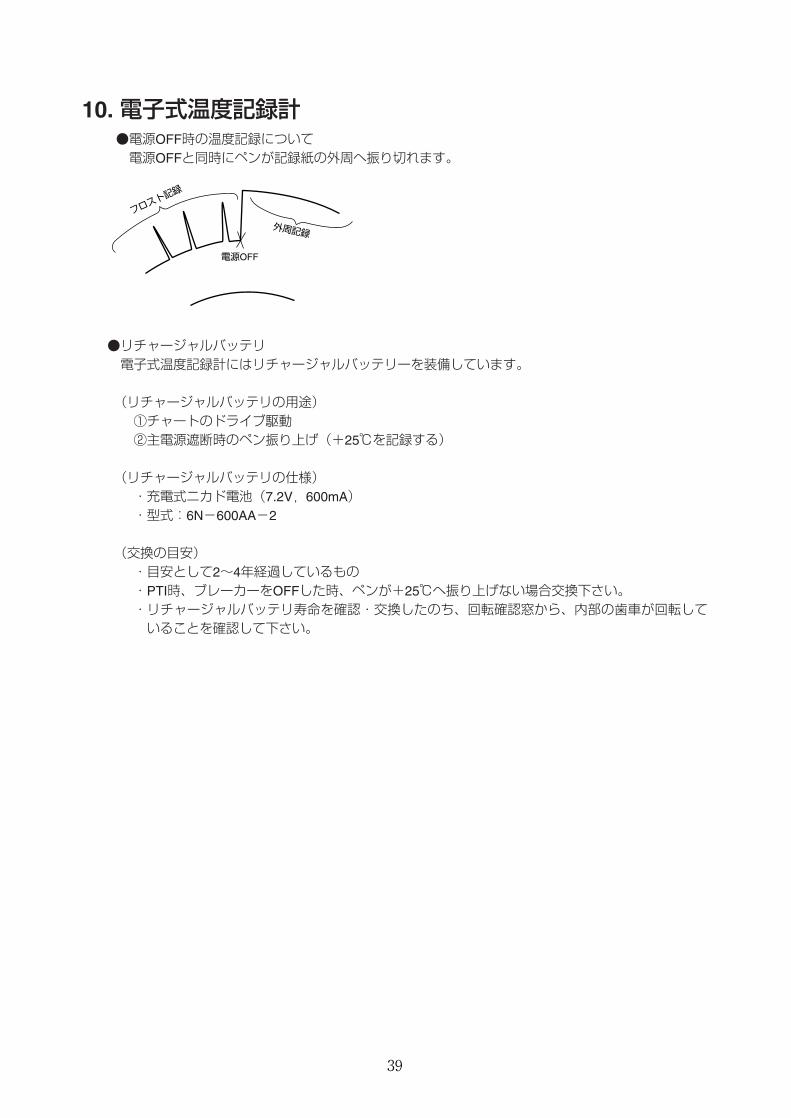
10. 電子式温度記録計●電源OFF時の温度記録について電源OFFと同時にペンが記録紙の外周へ振り切れます。
●リチャージャルバッテリ電子式温度記録計にはリチャージャルバッテリーを装備しています。
(リチャージャルバッテリの用途)①チャートのドライブ駆動②主電源遮断時のペン振り上げ(+25℃を記録する)
(リチャージャルバッテリの仕様)・充電式ニカド電池(7.2V,600mA)・型式:6N-600AA-2
(交換の目安)・目安として2~4年経過しているもの・PTI時、ブレーカーをOFFした時、ペンが+25℃へ振り上げない場合交換下さい。・リチャージャルバッテリ寿命を確認・交換したのち、回転確認窓から、内部の歯車が回転していることを確認して下さい。

40
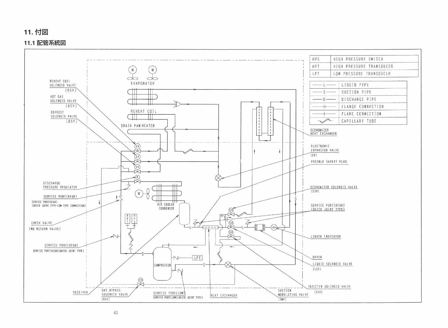
11. 付図
11.1 配管系統図
41
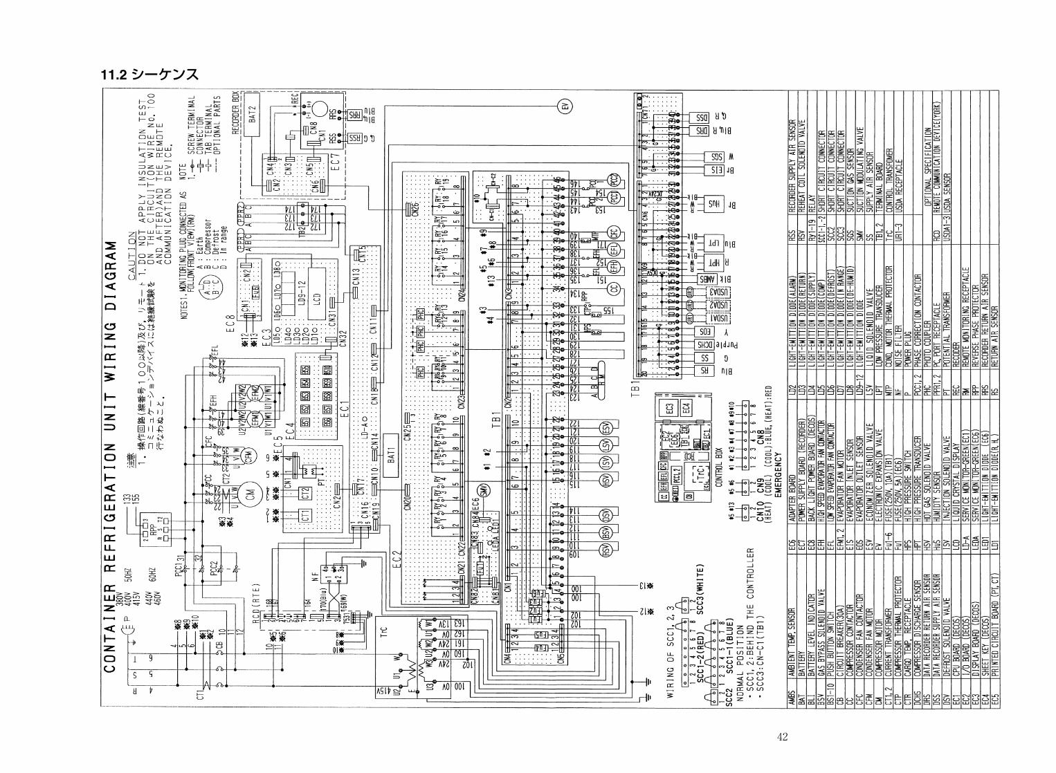
11.2 シーケンス
42
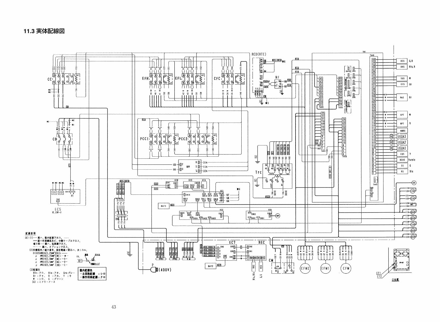
11.3 実体配線図
43

44
45
ORDERING INSTRUCTIONS
The parts list contains the parts of the DAIKIN Marine Type Container Refrigeration Units.Carefully read the following cautions before using the list.
1. When ordering the parts, be sure to describe Model No., Name of part and type.When ordering the parts No. are not shown in the PARTS NO. column, be sure todescribe DWG.NO..
2. The parts shown in the list are replacement or repairing on the spot only. Certain partsrequire a long time of delivery or are assembled in a set, so it is advisable to contactwith the nearest DAIKIN PARTS CENTRE.
パーツリスト使用上の注意
このパーツリストはダイキン海上コンテナ冷凍装置の部品を集録してあります。パーツリスト使用にあたっては、必ず次の注意事項をご一読の上使用していただくようお願いいたします。
1.部品のご注文の際は機種名、部品番号、および部品名、形式を必ずご指定ください。なお、部品番号欄が空白になっている部品は、図面番号で指示願います。
2.掲載部品の範囲は、あくまでも現地にて分解修理できるところまで記載しております。一部部品につき納期のかかるものおよびセット単位となるものもありますので、お近くのダイキンパーツセンター又はサービスステーションに相談願います。
本書は標準機と異なる箇所のみ記載しておりますので、本書に記載なき事項は別途発行パーツリスト(TR01-07)を併せて参照下さい。
The parts which are different from that of the standard model only are describedin this manual. Regarding the items which are not described in this manual, referto Parts List (TR01-07) as well.

46
47
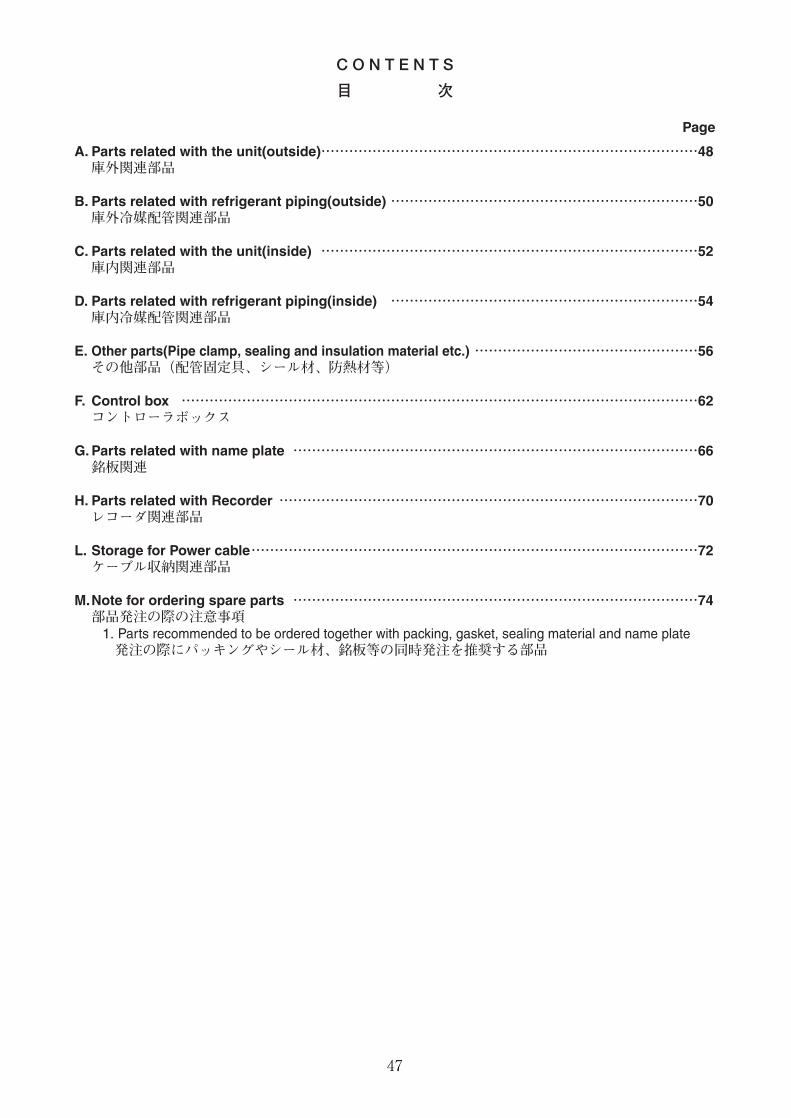
C O N T E N T S
目 次
Page
A. Parts related with the unit(outside)………………………………………………………………………48庫外関連部品
B. Parts related with refrigerant piping(outside) …………………………………………………………50庫外冷媒配管関連部品
C. Parts related with the unit(inside) ………………………………………………………………………52庫内関連部品
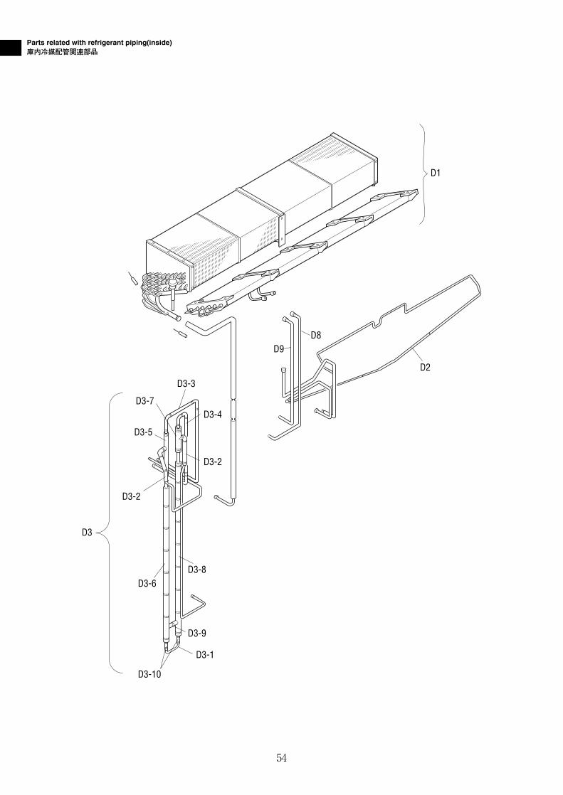
D. Parts related with refrigerant piping(inside) …………………………………………………………54庫内冷媒配管関連部品
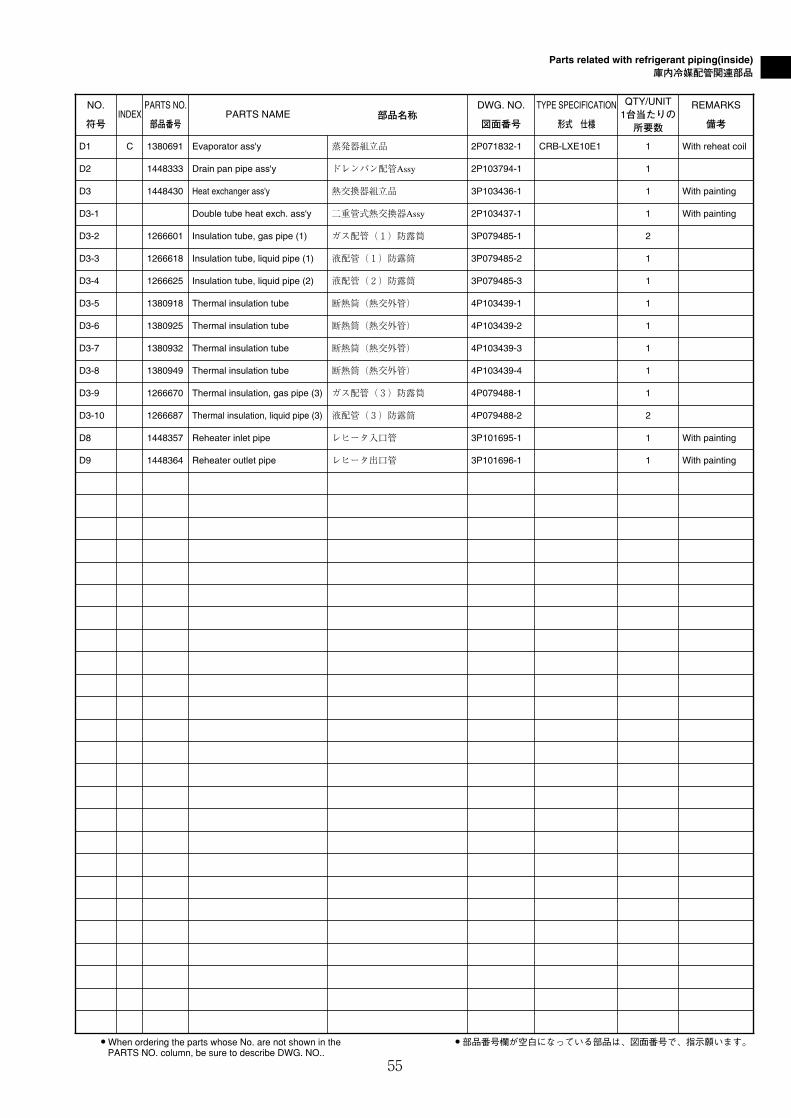
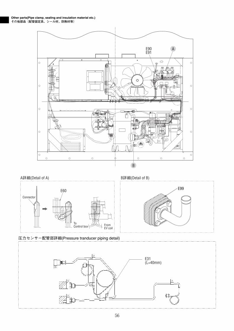
E. Other parts(Pipe clamp, sealing and insulation material etc.) …………………………………………56その他部品(配管固定具、シール材、防熱材等)
F. Control box …………………………………………………………………………………………………62コントローラボックス
G. Parts related with name plate ……………………………………………………………………………66銘板関連
H. Parts related with Recorder ………………………………………………………………………………70レコーダ関連部品
L. Storage for Power cable……………………………………………………………………………………72ケーブル収納関連部品
M.Note for ordering spare parts ……………………………………………………………………………74部品発注の際の注意事項
1. Parts recommended to be ordered together with packing, gasket, sealing material and name plate発注の際にパッキングやシール材、銘板等の同時発注を推奨する部品
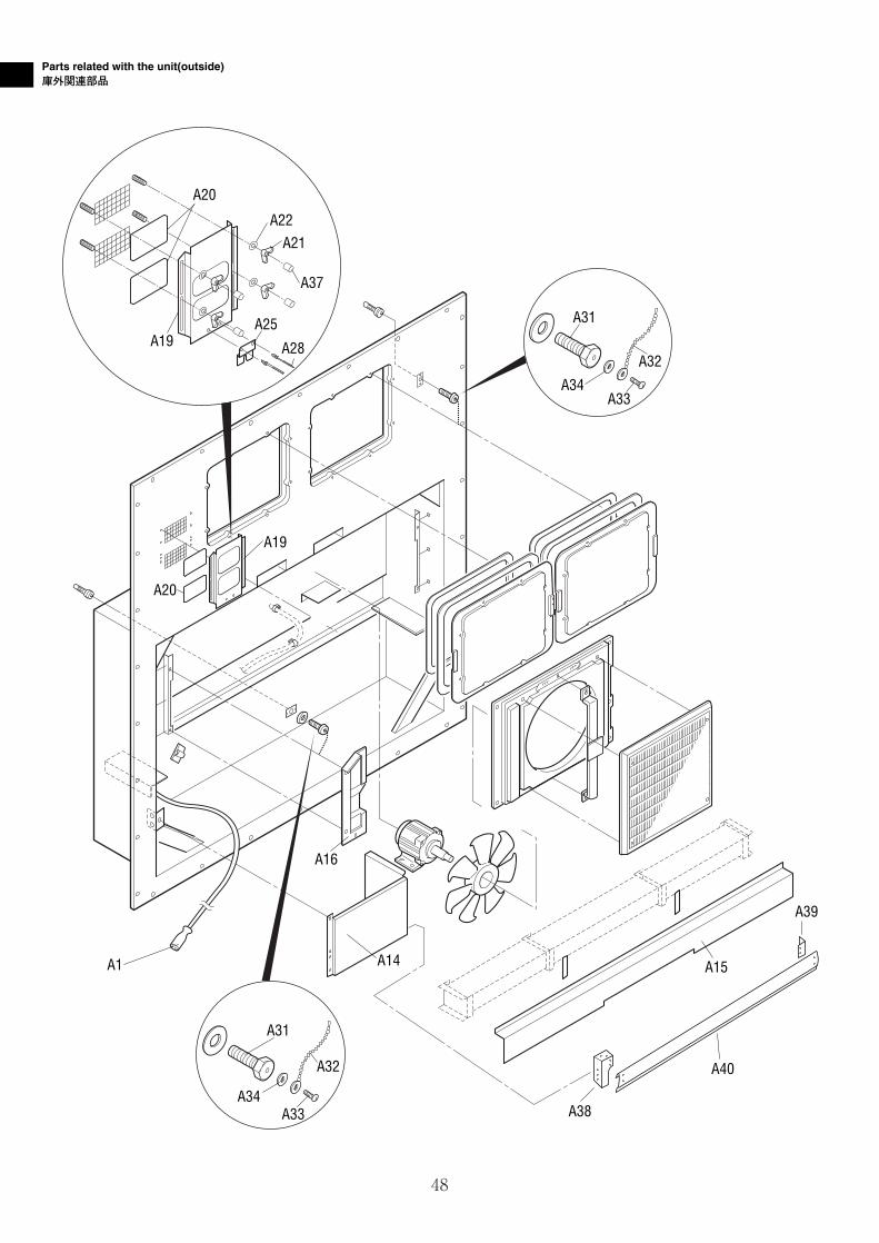
Parts related with the unit(outside)庫外関連部品
A20
A19
A31
A32
A33A34
A1
A31
A32
A33A34
A14
A16
A19
A21
A37
A22
A20
A28
A25
A39
A40
A15
A38
48
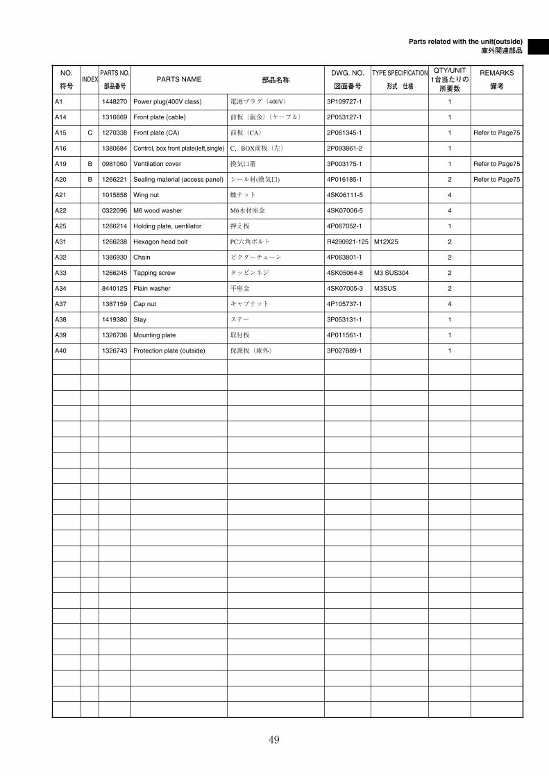
Parts related with the unit(outside)庫外関連部品
49
NO.
符号INDEX
PARTS NO.
部品番号PARTS NAME 部品名称
DWG. NO.
図面番号
TYPE SPECIFICATION
形式 仕様
QTY/UNIT1台当たりの所要数
REMARKS
備考
A1 1448270 Power plug(400V class) 電源プラグ(400V) 3P109727-1 1
A14 1316669 Front plate (cable) 前板(鈑金)(ケーブル) 2P053127-1 1
A16 1380684 Control, box front plate(left,single) C,BOX前板(左) 2P093861-2 1
A19 B 0981060 Ventilation cover 換気口蓋 3P003175-1 1 Refer to Page75
A20 B 1266221 Sealing material (access panel) シール材(換気口) 4P016185-1 2 Refer to Page75
A21 1015858 Wing nut 蝶ナット 4SK06111-5 4
A22 0322096 M6 wood washer M6木材座金 4SK07006-5 4
A25 1266214 Holding plate, uentilator 押え板 4P067052-1 1
A31 1266238 Hexagon head bolt PC六角ボルト R4290921-125 M12X25 2
A32 1386930 Chain ビクターチェーン 4P063801-1 2
A33 1266245 Tapping screw タッピンネジ 4SK05064-8 M3 SUS304 2
A34 844012S Plain washer 平座金 4SK07005-3 M3SUS 2
A37 1387159 Cap nut キャプナット 4P105737-1 4
A38 1419380 Stay ステー 3P053131-1 1
A39 1326736 Mounting plate 取付板 4P011561-1 1
A40 1326743 Protection plate (outside) 保護板(庫外) 3P027889-1 1
A15 C 1270338 Front plate (CA) 前板(CA) 2P061345-1 1 Refer to Page75
50
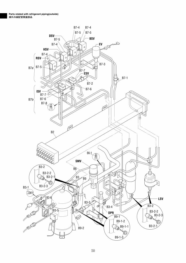
Parts related with refrigerant piping(outside)庫外冷媒配管関連部品
B7-5
B7-5
B7-4B7-4
DSVBSV
HSV
RSV
ISV
ESV
EVB7-4
B7-4
B7-5B7-5
B7a
B7b B7-6
B7-6
B2
B7-2
B7-3
B7-7
B7-7
B7-1
B7-8
B3-6
B9-2
DPR
B3-4
B9-1-2
B9-1-1
B9-1
B9-1-3
B3-2-2
B3-2-1
B3-2
B3-2-3
SMV
B9B3
B6
B3-5
B3-3
B3-2-2
B3-2
B3-2-1
B3-2-3
LSV
B3-1
B6-1
Parts related with refrigerant piping(outside)庫外冷媒配管関連部品
51
NO.
符号INDEX
PARTS NO.
部品番号PARTS NAME 部品名称
DWG. NO.
図面番号
TYPE SPECIFICATION
形式 仕様
QTY/UNIT1台当たりの所要数
REMARKS
備考
B3 Discharge pipe ass'y 吐出配管ASSY 2P090618-1 1
B3-1 1199167 Strainer ストレーナ 4P051389-1 1
B3-2 C 1178920 Service valve ass'y サービスバルブ組立品 3P048905-1 3
B3-2-1 B 1175921 Service valve cap キャップ 3P048905-1-KU 3
B3-2-2 B Service valve body 本体 3P048905-1-KA 3
B3-2-3 B 1178850 Valve core バルブコア 3P048905-1-KI 3
B3-3 B 0684220 Check valve 逆止弁 3SA27008-1 1
B3-4 A 1241361 Discharge pressure regulating valve 吐出圧力調整弁 3P074558-1 1 DPR
B3-5 1266276 Flange(convex) 吐出管フランジ(凸) 4P065933-1 1
B3-6 B 292011 Gauge joint(with check valve) 逆止弁付ゲージ接手 2PF00177-1 VCG2DA 1
B6 Injection tube ass'y インジェクション管組立品 3P093305-1 1
B7-8 0964166 Strainer ストレーナ 4P012568-1 1
B9 Suction piping ass'y(1) 吸入配管ASSY(1) 2P084863-1 1
B9-1 C 1178937 Service valve ass'y サービスバルブ組立品 3P048907-1 2
B9-1-1 B 1178867 Valve core バルブコア 3P048907-1-KI 2
B9-1-2 B Service valve body 本体 3P048907-1-KA 2
B9-1-3 B 1175914 Service valve cap キャップ 3P048907-1-KU 2
B9-2 1266315 Square flange 角フランジ 4PA61542-1 1
● When ordering the parts whose No. are not shown in thePARTS NO. column, be sure to describe DWG. NO..
● 部品番号欄が空白になっている部品は、図面番号で、指示願います。
B2 C 1387173 Air cooled condenser 空冷凝縮器 2P089486-1 CA-LXE10E1 1 With reheat coil
B6-1 0085296 Strainer ストレーナ R4697892 1
B7a Expansion valve pipe ass'y 膨張弁配管組立品 2P101637-1 1
B7-1 0975522 Filter フィルタ 3P011071-1 1
B7-2 0299134 Filter フィルタ 3SA26004-2 1
B7-3 A 1256495 Electronic expansion valve body ass'y 電子膨張弁本体組立品 2SA50010-2-KU 1 EV
B7-5 A 0955287 Solenoid valve coil 電磁弁コイル 3P010453-1 4 HSV, DSV ,BSV, RSV
B7b ISV, ESV pipe ass'y ISV, ESV配管組立品 2P090529-1 1
B7-6 A 0088738 NEV type solenoid valve body NEV型電磁弁本体 R3305099-1-KI NEV-202DXF 2 ISV, ESV
B7-7 A 0955287 Solenoid valve coil 電磁弁コイル 3P010453-1 2 ISV, ESV
B7-4 A 0944566 NEV type solenoid valve body NEV型電磁弁本体 R3305118-1 NEV-803DXF 4 HSV, DSV ,BSV, RSV
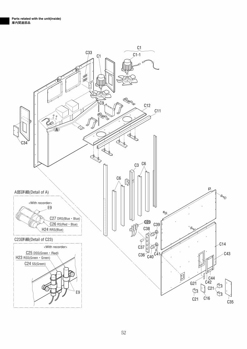
Parts related with the unit(inside)庫内関連部品
A部詳細(Detail of A)
C23詳細(Detail of C23)
C27 DRS(Blue・Blue)
C25 DSS(Green・Red)
C24 SS(Green)
H23 RSS(Green・Green)
C26 RS(Red・Blue)
H24 RRS(Blue)
E9
E9
<With recorder>
<With recorder>
C34
C33C1 C1-1
C1
C12C11
C3 C6
C6
C9
A
C23 C39
C37
C36
C38
C40
C14
C21C42G21
C44
C21 C16
C43
C35
C41
52
Parts related with the unit(inside)庫内関連部品
53
NO.
符号INDEX
PARTS NO.
部品番号PARTS NAME 部品名称
DWG. NO.
図面番号
TYPE SPECIFICATION
形式 仕様
QTY/UNIT1台当たりの所要数
REMARKS
備考
C1 A 0955340 Three phase AC fan motor 三相交流ファン電動機(ケーブル付) 3PA07524-5 SPRK91A-42 2 Cable length 3270
C1-1 A 0807333 Three phase AC fan motor 三相交流ファン電動機(ケーブル無) 3P07524-3 2 Without cable
C6 1380730 Rear stay(Reheat) 背面ステー(レヒート) 3P103621-1 t2.0 Aluminum 4
C11 1380778 Support plate, fan guide ファンガイド補強板 2P103496-1 1
C12 1380785 Fan guide ass'y ファンガイドASSY 3P103377-1 1
C14 1418426 Rear plate(lower) 裏板(下) 2P094960-2 1
C16 1380817 Inspection door 点検蓋 3P094961-1 t2.0 Aluminum 1
C21 1135125 Hinge 蝶番 3P043374-1 3
C24 A 1375310 Sensor(SS) センサー(SS) 3PA61769-11 ST9503-11(green) 1
C25 A 1375327 Sensor(DSS) センサー(DSS) 3PA61769-12 ST9503-12(green,red) 1
C27 A 1375341 Sensor(DRS) センサー(DRS) 3PA61769-14 ST9503-14(blue,red) 1
C33 1380831 Insect screen ass'y 防虫網組立品 3P009594-1 2
C34 1380848 Cover カバー 3P090387-1 1
C35 1266500 Inspection door(USDA) 点検蓋(USDA) 4P094962-1 1
C40 0991531 PC port connector パソコンポートコネクタ 3P010803-1 1
C41 1267541 Cap, PC port connector パソコンポートキャップ 3P010743-1 1
C42 1448294 Sealing material(USDA patch plate 3) シール材(USDA 当板3) 4P005225-1 1
C43 1448302 Sealing material(USDA patch plate 2) シール材(USDA 当板2) 4P005226-1 1
C44 1448319 Sealing material(USDA patch plate 1) シール材(USDA 当板1) 4P005221-1 2
C3 1380716 Center stay(Reheat) 中央ステー(レヒート) 3P092840-1 t2.5 Aluminum 1
C9 1410509 Fixing plate, fan guide ファンガイド固定板 3P083180-1 1
C26 A 1375334 Sensor(RS) センサー(RS) 3PA61769-13 ST9503-13(blue) 1
C36 1448287 Mounting plate, receptacles レセプタクル取付板 3P111485-1 1
C37 1266548 Vinyl tube ビニールチューブ 4P039446-1 TRANSPARENT 3
C38 0991548 Receptacle レセプタクルSHELL 3PA47173-1 3
C39 0767226 Cap, receptacle キャップ 4PA47172-1 3
G21 1448326 Name plate, USDA USDA銘板 3P113946-1 English 1 Refer to Page68
E9 0118273 Resin clamp 樹脂バンド NE41015-2 Milk white 3
H23 A 0798307 Sensor(RSS) センサー(RSS) 3PA61769-4 ST9503-4 1
H24 A 0798282 Sensor(RRS) センサー(RRS) 3PA61769-2 ST9503-2 1
Parts related with refrigerant piping(inside)庫内冷媒配管関連部品
D3-1
D3-10
D3-6
D3-2
D3-2
D1
D3-4
D3-3
D2
D8D9
D3-5
D3-7
D3
D3-9
D3-8
54
Parts related with refrigerant piping(inside)庫内冷媒配管関連部品
55
NO.
符号INDEX
PARTS NO.
部品番号PARTS NAME 部品名称
DWG. NO.
図面番号
TYPE SPECIFICATION
形式 仕様
QTY/UNIT1台当たりの所要数
REMARKS
備考
D1 C 1380691 Evaporator ass'y 蒸発器組立品 2P071832-1 CRB-LXE10E1 1 With reheat coil
D2 1448333 Drain pan pipe ass'y ドレンパン配管Assy 2P103794-1 1
D3 1448430 Heat exchanger ass'y 熱交換器組立品 3P103436-1 1 With painting
D3-1 Double tube heat exch. ass'y 二重管式熱交換器Assy 2P103437-1 1 With painting
D3-2 1266601 Insulation tube, gas pipe (1) ガス配管(1)防露筒 3P079485-1 2
D3-3 1266618 Insulation tube, liquid pipe (1) 液配管(1)防露筒 3P079485-2 1
D3-4 1266625 Insulation tube, liquid pipe (2) 液配管(2)防露筒 3P079485-3 1
D3-5 1380918 Thermal insulation tube 断熱筒(熱交外管) 4P103439-1 1
D3-6 1380925 Thermal insulation tube 断熱筒(熱交外管) 4P103439-2 1
D3-7 1380932 Thermal insulation tube 断熱筒(熱交外管) 4P103439-3 1
D3-8 1380949 Thermal insulation tube 断熱筒(熱交外管) 4P103439-4 1
D3-9 1266670 Thermal insulation, gas pipe (3) ガス配管(3)防露筒 4P079488-1 1
D3-10 1266687 Thermal insulation, liquid pipe (3) 液配管(3)防露筒 4P079488-2 2
● When ordering the parts whose No. are not shown in thePARTS NO. column, be sure to describe DWG. NO..
● 部品番号欄が空白になっている部品は、図面番号で、指示願います。
D8 1448357 Reheater inlet pipe レヒータ入口管 3P101695-1 1 With painting
D9 1448364 Reheater outlet pipe レヒータ出口管 3P101696-1 1 With painting
E31(L=40mm)
Other parts(Pipe clamp, sealing and insulation material etc.)その他部品(配管固定具、シール材、防熱材等)
A詳細(Detail of A) B詳細(Detail of B)
E60
E90E91
A
Connector
ToControl box From
EV coil
B
56
圧力センサー配管部詳細(Pressure tranducer piping detail)
E99
57
E60
E92
E90E91
E60
E60
E87
E87
E71
E5
E29
E96
E92
E74
E24(L=30mm)
E97
Other parts(Pipe clamp, sealing and insulation material etc.)その他部品(配管固定具、シール材、防熱材等)
※(L = XX mm) indicates the length of cushion rubber E35.(Cut to suit pipe size.)
※(L = XX mm)と表記のものは、緩衝ゴム(E35)の長さです。(配管のサイズに合わせて切って使用ください。)
矢視C/D(View C/D)
矢視H(View H)
冷媒配管詳細 ( Refrigerant piping detail )E詳細(Detail E)
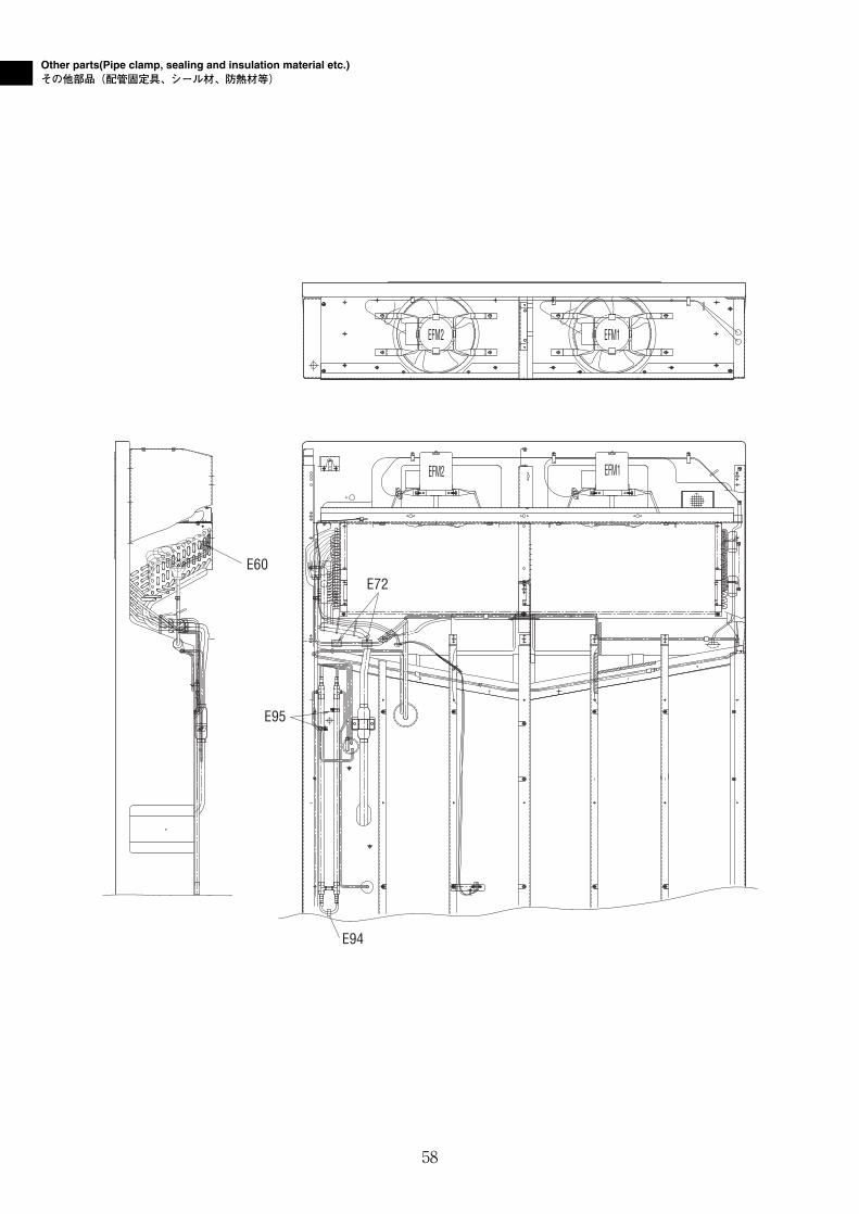
Other parts(Pipe clamp, sealing and insulation material etc.)その他部品(配管固定具、シール材、防熱材等)
EFM2
EFM1
EFM1
EFM2
E72E60
E95
E94
58
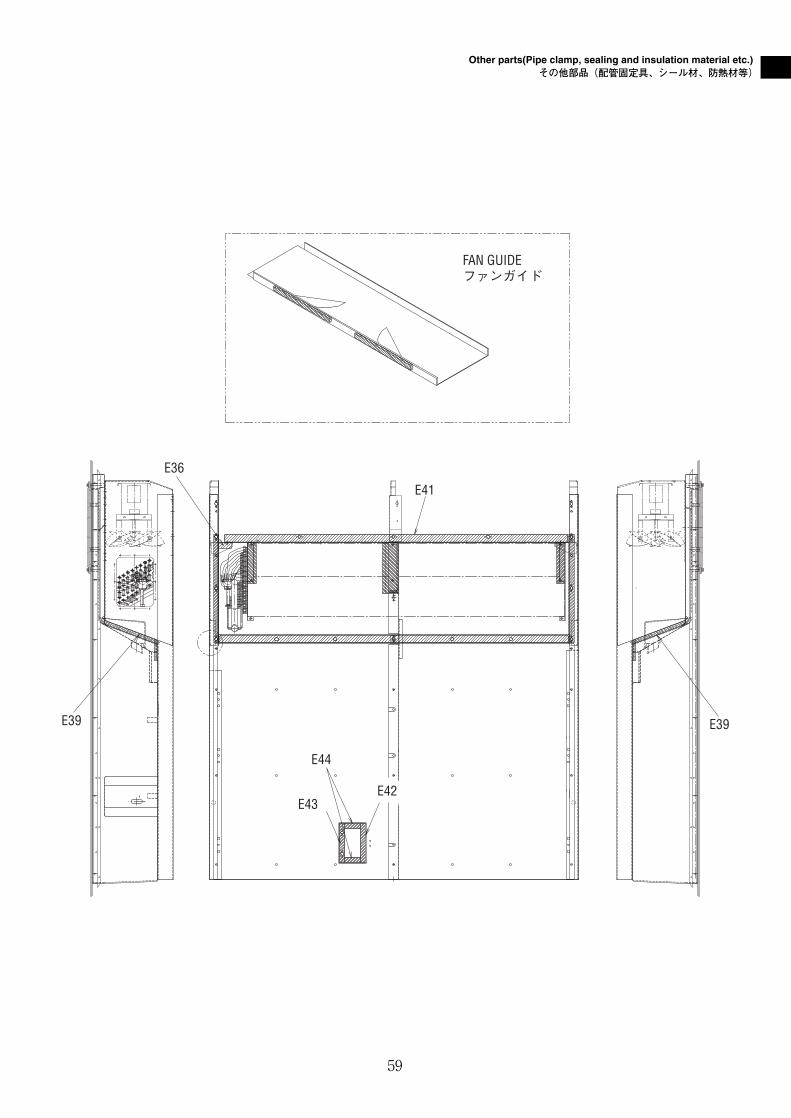
Other parts(Pipe clamp, sealing and insulation material etc.)その他部品(配管固定具、シール材、防熱材等)
FAN GUIDEファンガイド
E43
E44
E39E39
E42
E41
E36
59
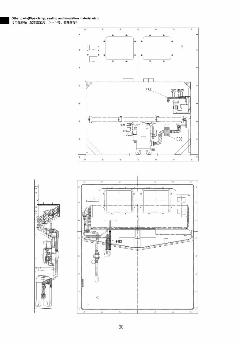
Other parts(Pipe clamp, sealing and insulation material etc.)その他部品(配管固定具、シール材、防熱材等)
E93
E61
E98
60
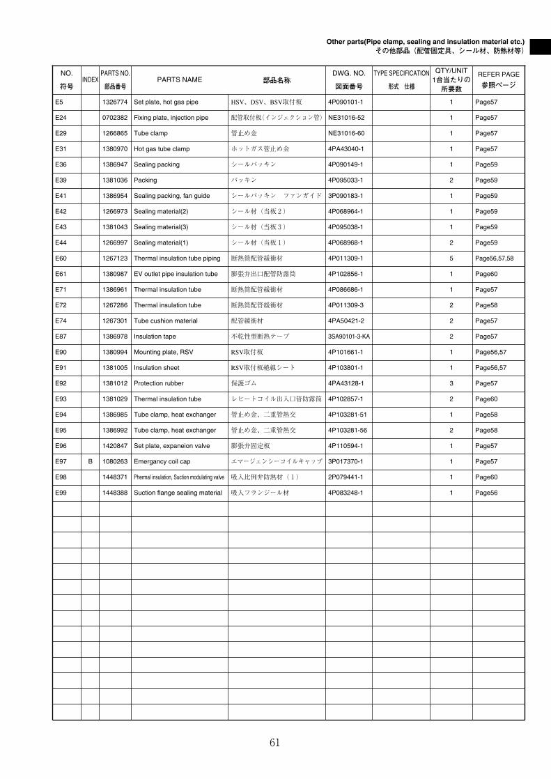
Other parts(Pipe clamp, sealing and insulation material etc.)その他部品(配管固定具、シール材、防熱材等)
61
NO.
符号INDEX
PARTS NO.
部品番号PARTS NAME 部品名称
DWG. NO.
図面番号
TYPE SPECIFICATION
形式 仕様
QTY/UNIT1台当たりの所要数
REFER PAGE
参照ページ
E5 1326774 Set plate, hot gas pipe HSV、DSV、BSV取付板 4P090101-1 1 Page57
E24 0702382 Fixing plate, injection pipe 配管取付板(インジェクション管) NE31016-52 1 Page57
E29 1266865 Tube clamp 管止め金 NE31016-60 1 Page57
E31 1380970 Hot gas tube clamp ホットガス管止め金 4PA43040-1 1 Page57
E36 1386947 Sealing packing シールパッキン 4P090149-1 1 Page59
E39 1381036 Packing パッキン 4P095033-1 2 Page59
E41 1386954 Sealing packing, fan guide シールパッキン ファンガイド 3P090183-1 1 Page59
E42 1266973 Sealing material(2) シール材(当板2) 4P068964-1 1 Page59
E43 1381043 Sealing material(3) シール材(当板3) 4P095038-1 1 Page59
E44 1266997 Sealing material(1) シール材(当板1) 4P068968-1 2 Page59
E60 1267123 Thermal insulation tube piping 断熱筒配管緩衝材 4P011309-1 5 Page56,57,58
E61 1380987 EV outlet pipe insulation tube 膨張弁出口配管防露筒 4P102856-1 1 Page60
E71 1386961 Thermal insulation tube 断熱筒配管緩衝材 4P086686-1 1 Page57
E72 1267286 Thermal insulation tube 断熱筒配管緩衝材 4P011309-3 2 Page58
E74 1267301 Tube cushion material 配管緩衝材 4PA50421-2 2 Page57
E87 1386978 Insulation tape 不乾性型断熱テープ 3SA90101-3-KA 2 Page57
E90 1380994 Mounting plate, RSV RSV取付板 4P101661-1 1 Page56,57
E91 1381005 Insulation sheet RSV取付板絶線シート 4P103801-1 1 Page56,57
E92 1381012 Protection rubber 保護ゴム 4PA43128-1 3 Page57
E93 1381029 Thermal insulation tube レヒートコイル出入口管防露筒 4P102857-1 2 Page60
E94 1386985 Tube clamp, heat exchanger 管止め金、二重管熱交 4P103281-51 1 Page58
E95 1386992 Tube clamp, heat exchanger 管止め金、二重管熱交 4P103281-56 2 Page58
E96 1420847 Set plate, expaneion valve 膨張弁固定板 4P110594-1 1 Page57
E97 B 1080263 Emergancy coil cap エマージェンシーコイルキャップ 3P017370-1 1 Page57
E98 1448371 Phermal insulation, Suction modulating valve 吸入比例弁防熱材(1) 2P079441-1 1 Page60
E99 1448388 Suction flange sealing material 吸入フランジール材 4P083248-1 1 Page56
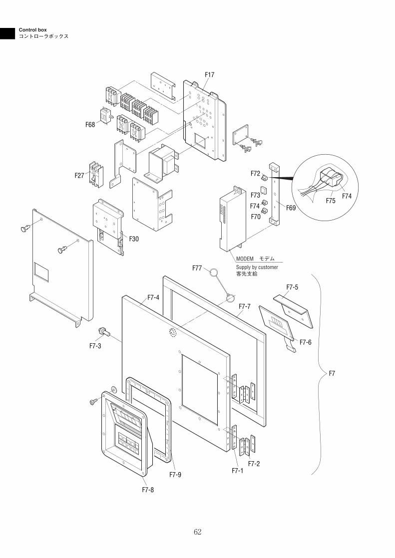
Control boxコントローラボックス
MODEM モデム
Supply by customer客先支給
F7-2F7-1F7-9
F7-3
F7-8
F7-4F7-7
F7-5
F7-6
F30
F77
F27
F68
F17
F7
F69
F72
F73
F74
F70
F75F74
62
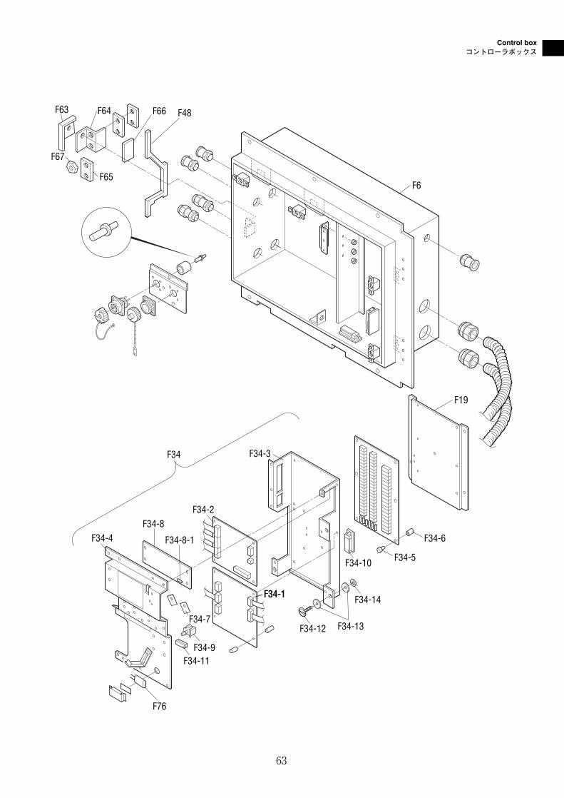
Control boxコントローラボックス
F34-1
F34-7
F34 F34-3
F34-2
F34-4
F34-1
F19
F6
F66 F48F64F63
F65
F67
F34-8-1
F34-8
F34-11
F76
F34-12 F34-13
F34-14
F34-10 F34-5
F34-6
F34-9
63
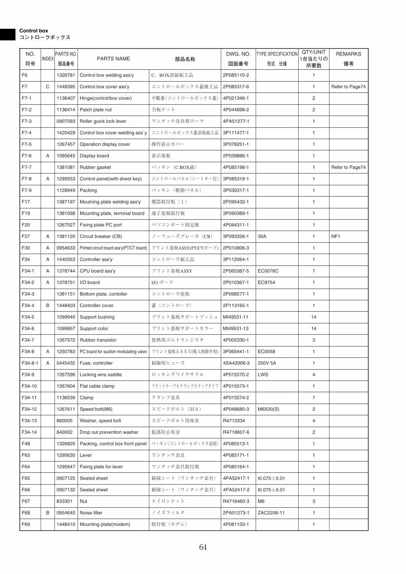
Control boxコントローラボックス
64
NO.
符号INDEX
PARTS NO.
部品番号PARTS NAME 部品名称
DWG. NO.
図面番号
TYPE SPECIFICATION
形式 仕様
QTY/UNIT1台当たりの所要数
REMARKS
備考
F6 1326781 Control box welding ass'y C.BOX溶接組立品 2P085110-2 1
F7 C 1448395 Control box cover ass'y コントロールボックス蓋組立品 2P085317-6 1 Refer to Page74
F7-1 1136407 Hinge(control/box cover) 平蝶番(コントロールボックス蓋) 4P021346-1 2
F7-2 1136414 Patch plate nut 当板ナット 4P044898-2 2
F7-3 0907093 Roller guick lock lever ワンタッチ金具用ローラ 4PA51277-1 1
F7-4 1420429 Control box cover welding ass`y コントロールボックス蓋溶接組立品 3P111477-1 1
F7-5 1267457 Operation display cover 操作表示カバー 3P078251-1 1
F7-6 A 1095645 Display board 表示基板 2P039886-1 1
F7-7 1381081 Rubber gasket パッキン(C.BOX蓋) 4P085198-1 1 Refer to Page74
F7-8 A 1295553 Control panel(with sheet key) コントロールパネル(シートキー付) 3P085319-1 1
F7-9 1128949 Packing パッキン(樹脂パネル) 3P030317-1 1
F17 1387197 Moutning plate welding ass'y 機器取付板(1) 2P095432-1 1
F19 1381098 Mounting plate, terminal board 端子基板取付板 3P090389-1 1
F34-3 1381151 Bottom plate, contoller コントローラ底板 2P098577-1 1
F34-9 1267596 Locking wire saddle ロッキングワイヤサドル 4P015570-2 LWS 4
F34-10 1267604 Flat cable clamp フラットケーブルクランプスナップタイプ 4P015573-1 1
F34-11 1136539 Clamp クランプ金具 4P015574-2 1
F34-12 1267611 Speed bolt(M6) スピードボルト(M6) 4P048680-3 M6X20(S) 2
F48 1326820 Packing, control box front panel パッキン(コントロールボックス前板) 4P085513-1 1
F63 1295630 Lever ワンタッチ金具 4P085171-1 1
F20 1267527 Fixing plate PC port パソコンポート固定板 4P044311-1 1
F27 A 1381120 Circuit breaker (CB) ノーフューズブレーカ(CB) 3P093326-1 30A 1 NF1
F30 A 0954633 Printed circuit board ass'y(PT/CT board) プリント基板ASSY(PT/CTボード) 2P010906-3 1
F34 A 1440353 Controller ass'y コントローラ組立品 3P112064-1 1
F34-1 A 1378744 CPU board ass'y プリント基板ASSY 2P065387-5 EC0076C 1
F34-2 A 1378751 I/O board I/O ボード 2P010367-1 EC9754 1
F34-4 B 1448403 Controller cover 蓋(コントローラ) 2P113165-1 1
F34-5 1099940 Support bushing プリント基板サポートブッシュ MI49531-11 14
F34-6 1099957 Support color プリント基板サポートカラー MI49531-13 14
F34-7 1267572 Rubber transistor 放熱用ゴムトランジスタ 4P005330-1 3
F34-8 A 1250783 PC board for suction modulating valve プリント基板ASSY(吸入制御弁用) 3P065441-1 EC0058 1
F34-8-1 A 0445432 Fuse, controller 制御用ヒューズ 4SA42006-3 250V 5A 1
F69 1448410 Mounting plate(modem) 取付板(モデム) 4P081133-1 1
F34-13 860005 Washer, speed bolt スピードボルト用座金 R4713334 4
F64 1295647 Fixing plate for lever ワンタッチ金具取付板 4P085164-1 1
F65 0907125 Sealed sheet 絶縁シート(ワンタッチ金具) 4PA52417-1 t0.075±0.01 1
F66 0907132 Sealed sheet 絶縁シート(ワンタッチ金具) 4PA52417-2 t0.075±0.01 1
F34-14 840002 Drop out prevention washer 脱落防止座金 R4718607-6 2
F67 833301 Nut ナイロンナット R4716460-3 M6 3
F68 B 0954640 Noise filter ノイズフィルタ 2PA51273-1 ZAC2206-11 1
Control boxコントローラボックス
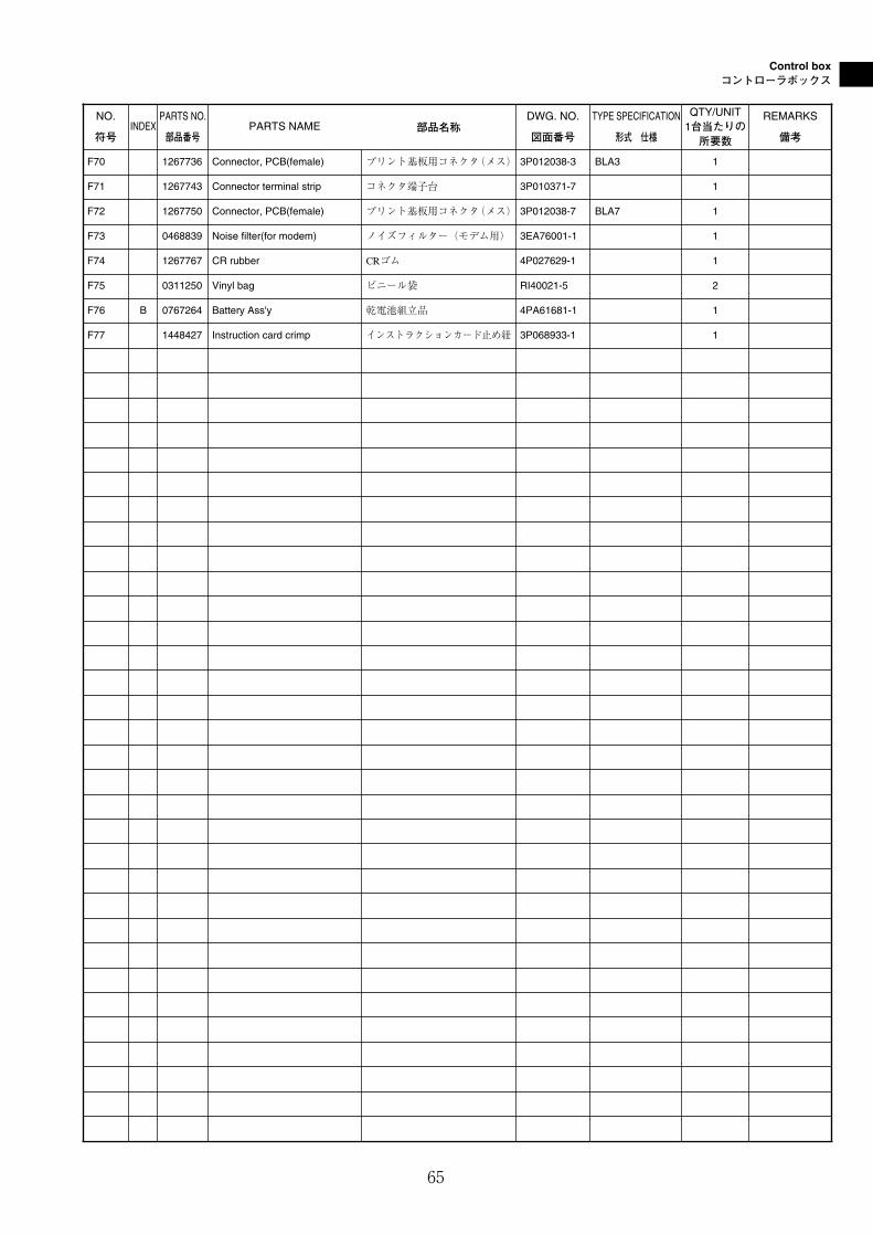
65
NO.
符号INDEX
PARTS NO.
部品番号PARTS NAME 部品名称
DWG. NO.
図面番号
TYPE SPECIFICATION
形式 仕様
QTY/UNIT1台当たりの所要数
REMARKS
備考
F70 1267736 Connector, PCB(female) プリント基板用コネクタ(メス) 3P012038-3 BLA3 1
F72 1267750 Connector, PCB(female) プリント基板用コネクタ(メス) 3P012038-7 BLA7 1
F73 0468839 Noise filter(for modem) ノイズフィルター(モデム用) 3EA76001-1 1
F74 1267767 CR rubber CRゴム 4P027629-1 1
F75 0311250 Vinyl bag ビニール袋 RI40021-5 2
F76 B 0767264 Battery Ass'y 乾電池組立品 4PA61681-1 1
F77 1448427 Instruction card crimp インストラクションカード止め紐 3P068933-1 1
F71 1267743 Connector terminal strip コネクタ端子台 3P010371-7 1
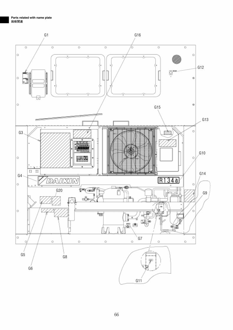
Parts related with name plate銘板関連
G1 G16
G12
G3
G4
G20
G5
G6
G8
G11
G7
G9
G14
G10
G13
G15
66
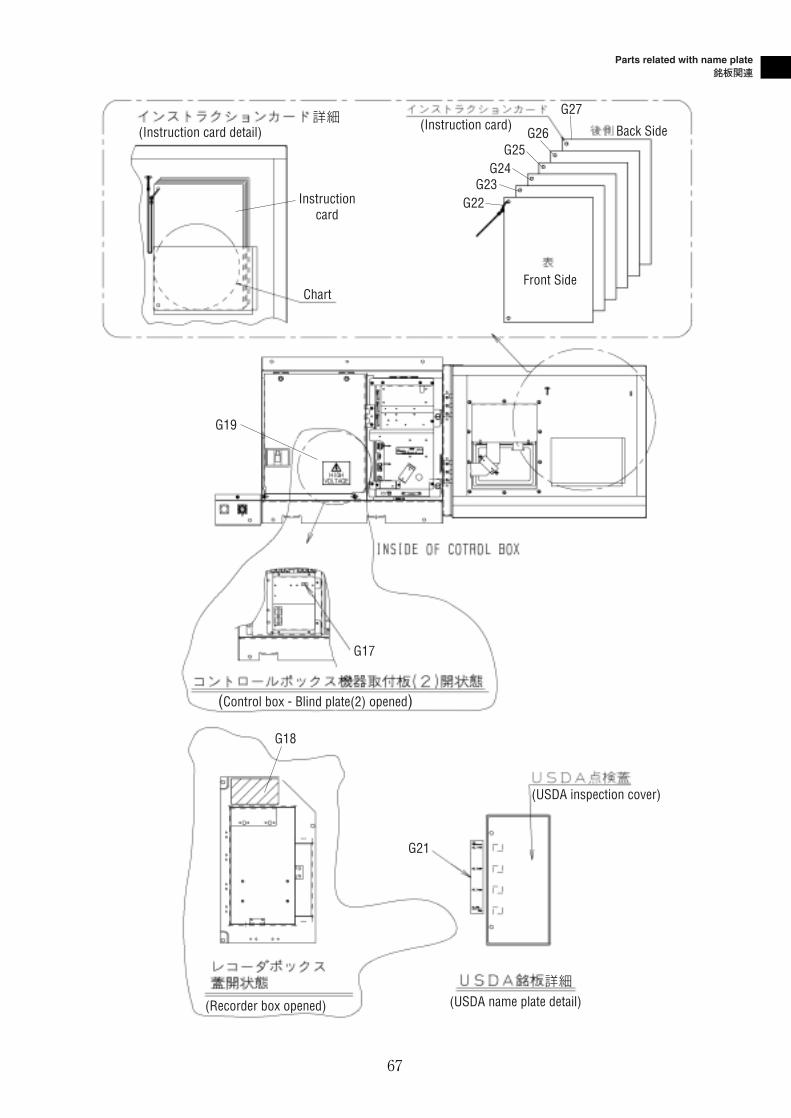
67
G27
Back Side
Front Side
G26G25
G24G23
G22
G19
G17
G21
G18
Chart
Instructioncard
(Instruction card detail) (Instruction card)詳細
(Control box - Blind plate(2) opened)
(USDA inspection cover)
詳細
(USDA name plate detail)(Recorder box opened)
Parts related with name plate銘板関連
Parts related with name plate銘板関連
68
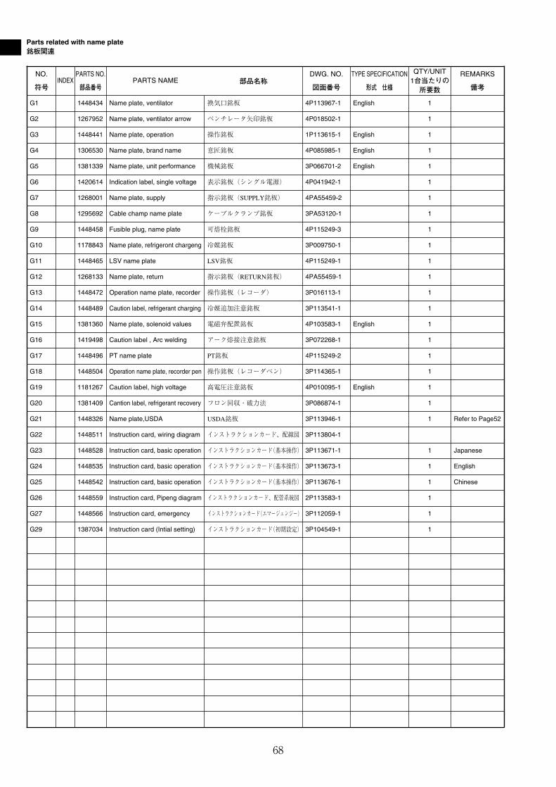
NO.
符号INDEX
PARTS NO.
部品番号PARTS NAME 部品名称
DWG. NO.
図面番号
TYPE SPECIFICATION
形式 仕様
QTY/UNIT1台当たりの所要数
REMARKS
備考
G1 1448434 Name plate, ventilator 換気口銘板 4P113967-1 English 1
G2 1267952 Name plate, ventilator arrow ベンチレータ矢印銘板 4P018502-1 1
G3 1448441 Name plate, operation 操作銘板 1P113615-1 English 1
G4 1306530 Name plate, brand name 意匠銘板 4P085985-1 English 1
G5 1381339 Name plate, unit performance 機械銘板 3P066701-2 English 1
G7 1268001 Name plate, supply 指示銘板(SUPPLY銘板) 4PA55459-2 1
G8 1295692 Cable champ name plate ケーブルクランプ銘板 3PA53120-1 1
G9 1448458 Fusible plug, name plate 可熔栓銘板 4P115249-3 1
G10 1178843 Name plate, refrigeront chargeng 冷媒銘板 3P009750-1 1
G11 1448465 LSV name plate LSV銘板 4P115249-1 1
G12 1268133 Name plate, return 指示銘板(RETURN銘板) 4PA55459-1 1
G13 1448472 Operation name plate, recorder 操作銘板(レコーダ) 3P016113-1 1
G14 1448489 Caution label, refrigerant charging 冷媒追加注意銘板 3P113541-1 1
G15 1381360 Name plate, solenoid values 電磁弁配置銘板 4P103583-1 English 1
G16 1419498 Caution label , Arc welding アーク熔接注意銘板 3P072268-1 1
G17 1448496 PT name plate PT銘板 4P115249-2 1
G26 1448559 Instruction card, Pipeng diagram インストラクションカード、配管系統図 2P113583-1 1
G18 1448504 Operation name plate, recorder pen 操作銘板(レコーダペン) 3P114365-1 1
G19 1181267 Caution label, high voltage 高電圧注意銘板 4P010095-1 English 1
G20 1381409 Cantion label, refrigerant recovery フロン回収・破力法 3P086874-1 1
G21 1448326 Name plate,USDA USDA銘板 3P113946-1 1 Refer to Page52
G22 1448511 Instruction card, wiring diagram インストラクションカード、配線図 3P113804-1
G23 1448528 Instruction card, basic operation インストラクションカード(基本操作) 3P113671-1 1 Japanese
G24 1448535 Instruction card, basic operation インストラクションカード(基本操作) 3P113673-1 1 English
G25 1448542 Instruction card, basic operation インストラクションカード(基本操作) 3P113676-1 1 Chinese
G27 1448566 Instruction card, emergency インストラクションカード(エマージェンジー) 3P112059-1 1
G29 1387034 Instruction card (Intial setting) インストラクションカード(初期設定) 3P104549-1 1
G6 1420614 Indication label, single voltage 表示銘板(シングル電源) 4P041942-1 1
Parts related with name plate銘板関連
69
NO.
符号INDEX
PARTS NO.
部品番号PARTS NAME 部品名称
DWG. NO.
図面番号
TYPE SPECIFICATION
形式 仕様
QTY/UNIT1台当たりの所要数
REMARKS
備考
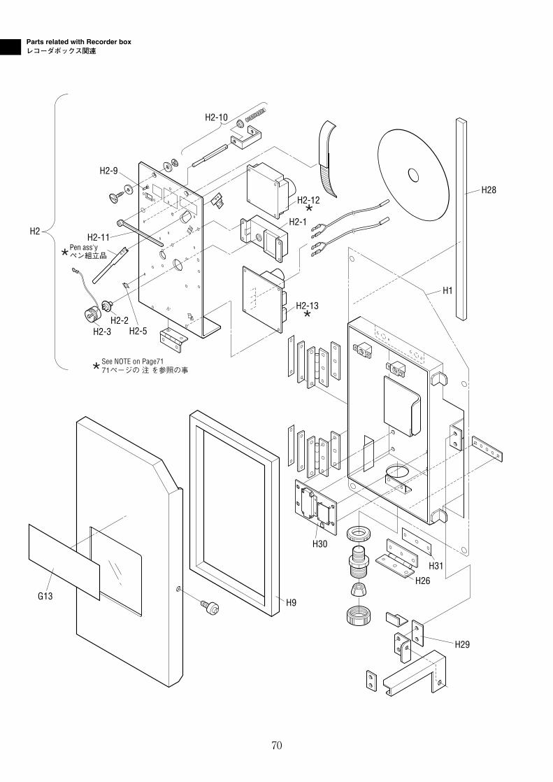
Parts related with Recorder boxレコーダボックス関連
See NOTE on Page7171ページの 注 を参照の事
H2-10
H2-9
H2-11Pen ass'yペン組立品
H2-3
H2
H2-2H2-5
H2-1
H2-12
H2-13
H29
H26
H31
H9G13
H30
H1
H28
70
71
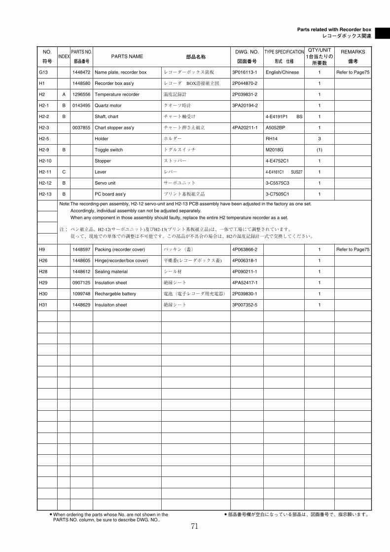
Parts related with Recorder boxレコーダボックス関連
NO.
符号INDEX
PARTS NO.
部品番号PARTS NAME 部品名称
DWG. NO.
図面番号
TYPE SPECIFICATION
形式 仕様
QTY/UNIT1台当たりの所要数
REMARKS
備考
H1 1448580 Recorder box ass'y レコーダ BOX溶接組立図 2P044870-2 1
H2 A 1296556 Temperature recorder 温度記録計 2P039831-2 1
H2-1 B 0143495 Quartz motor クオーツ時計 3PA20194-2 1
H2-2 B Shaft, chart チャート軸受け 4-E4191P1 BS 1
H2-3 0037855 Chart stopper ass'y チャート押さえ組立 4PA20211-1 A5052BP 1
H2-5 Holder ホルダー RH14 3
H2-9 B Toggle switch トグルスイッチ M2018G (1)
H2-10 Stopper ストッパー 4-E4752C1 1
H2-11 C Lever レバー 4-E4161C1 SUS27 1
H2-12 B Servo unit サーボユニット 3-C5575C3 1
H2-13 B PC board ass'y プリント基板組立品 3-C7505C1 1
Note:The recording-pen assembly, H2-12 servo-unit and H2-13 PCB assembly have been adjusted in the factory as one set.
Accordingly, individual assembly can not be adjusted separately.
When any component in those assembly should faulty, replace the entire H2 temperature recorder as a set.
注: ペン組立品、H2-12(サーボユニット)及びH2-13(プリント基板組立品)は、一体で工場にて調整されています。従って、現地での単体での調整は不可能です。この部品が不具合の場合は、H2の温度記録計一式で交換してください。
H9 1448597 Packing (recorder cover) パッキン(蓋) 4P063866-2 1 Refer to Page75
H26 1448605 Hinge(recorder/box cover) 平蝶番(レコーダボックス蓋) 4P006318-1 1
H28 1448612 Sealing material シール材 4P090211-1 1
H29 0907125 Insulation sheet 絶縁シート 4PA52417-1 1
H30 1099748 Rechargeble battery 電池(電子レコーダ用充電器) 2P039830-1 1
H31 1448629 Insulaiton sheet 絶縁シート 3P007352-5 1
G13 1448472 Name plate, recorder box レコーダーボックス銘板 3P016113-1 English/Chinese 1 Refer to Page75
● When ordering the parts whose No. are not shown in thePARTS NO. column, be sure to describe DWG. NO..
● 部品番号欄が空白になっている部品は、図面番号で、指示願います。
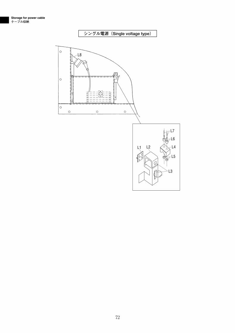
Storage for power cableケーブル収納
72
シングル電源(Single voltage type)
L2L1
L3
L6
L4
L5
L7
L8
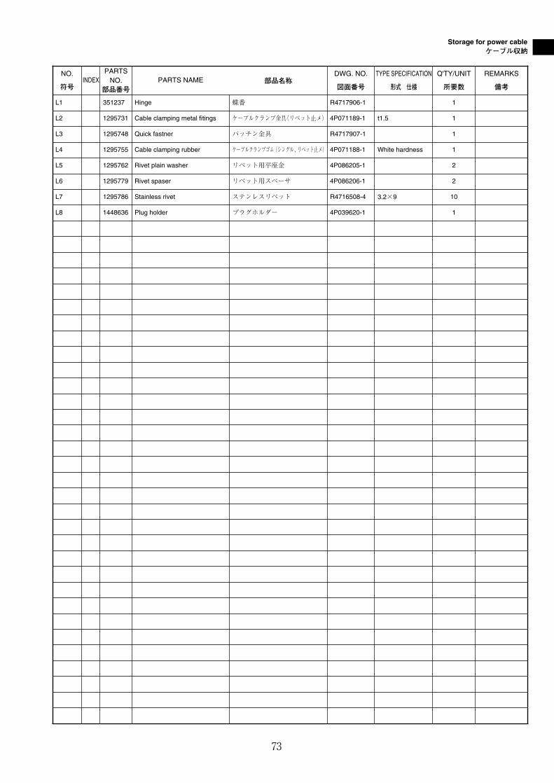
Storage for power cableケーブル収納
73
L1 351237 Hinge 蝶番 R4717906-1 1
L2 1295731 Cable clamping metal fitings ケーブルクランプ金具(リベット止メ) 4P071189-1 t1.5 1
L3 1295748 Quick fastner パッチン金具 R4717907-1 1
L4 1295755 Cable clamping rubber ケーブルクランプゴム(シングル、リベット止メ) 4P071188-1 White hardness 1
L5 1295762 Rivet plain washer リベット用平座金 4P086205-1 2
L6 1295779 Rivet spaser リベット用スペーサ 4P086206-1 2
L7 1295786 Stainless rivet ステンレスリベット R4716508-4 3.2×9 10
L8 1448636 Plug holder プラグホルダー 4P039620-1 1
NO.
符号INDEX
PARTS NO.
部品番号PARTS NAME 部品名称
DWG. NO.
図面番号
TYPE SPECIFICATION
形式 仕様
Q'TY/UNIT
所要数
REMARKS
備考
74
Notes for ordering spare parts部品発注の際の注意事項
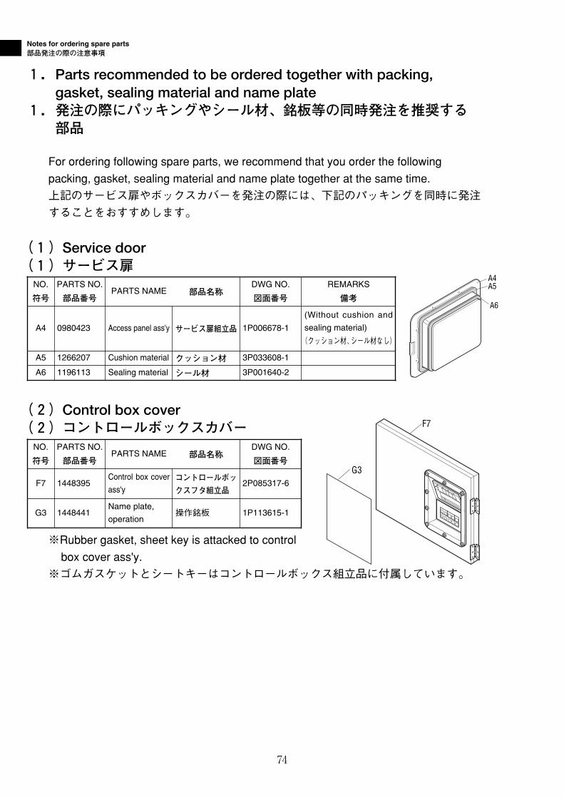
1.Parts recommended to be ordered together with packing,gasket, sealing material and name plate
1.発注の際にパッキングやシール材、銘板等の同時発注を推奨する部品
For ordering following spare parts, we recommend that you order the followingpacking, gasket, sealing material and name plate together at the same time.上記のサービス扉やボックスカバーを発注の際には、下記のパッキングを同時に発注することをおすすめします。
(1)Service door(1)サービス扉
(2)Control box cover(2)コントロールボックスカバー
※Rubber gasket, sheet key is attacked to controlbox cover ass'y.
※ゴムガスケットとシートキーはコントロールボックス組立品に付属しています。
NO.
符号
PARTS NO.
部品番号PARTS NAME 部品名称
REMARKS
備考
A4 0980423 Access panel ass'y サービス扉組立品
(Without cushion and
sealing material)
(クッション材、シール材なし)
A6 1196113 Sealing material シール材
F7
G3
NO.
符号
PARTS NO.
部品番号PARTS NAME 部品名称
DWG NO.
図面番号
F7 1448395Control box cover
ass'yコントロールボッ
クスフタ組立品2P085317-6
DWG NO.
図面番号
1P006678-1
A5 1266207 Cushion material クッション材 3P033608-1
3P001640-2
A4A5
A6
G3 1448441Name plate,
operation操作銘板 1P113615-1
75
Notes for ordering spare parts部品発注の際の注意事項
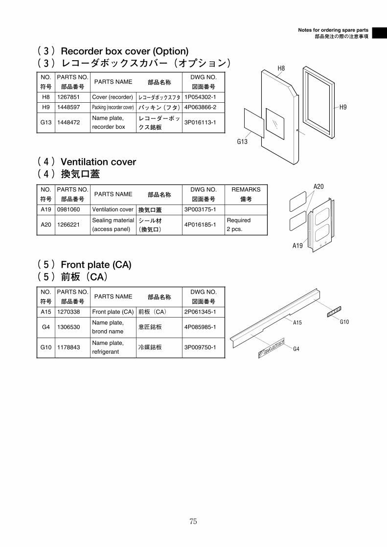
(4)Ventilation cover(4)換気口蓋
(5)Front plate (CA)(5)前板(CA)
NO.
符号
PARTS NO.
部品番号PARTS NAME 部品名称
REMARKS
備考
A19 0981060 Ventilation cover 換気口蓋
A19
A20
NO.
符号
PARTS NO.
部品番号PARTS NAME 部品名称
DWG NO.
図面番号
A15 1270338 Front plate (CA) 前板(CA) 2P061345-1
G10 1178843Name plate,
refrigerant冷媒銘板 3P009750-1
G4 1306530Name plate,
brond name意匠銘板 4P085985-1
A15
G4
G10R 1 3 4 a
DWG NO.
図面番号
3P003175-1
A20 1266221Sealing material
(access panel)シール材
(換気口)4P016185-1
Required
2 pcs.
(3)Recorder box cover (Option)(3)レコーダボックスカバー(オプション)
G13
H8
H9
NO.
符号
PARTS NO.
部品番号PARTS NAME 部品名称
DWG NO.
図面番号
H8 1267851 Cover (recorder) レコーダボックスフタ 1P054302-1
G13 1448472Name plate,
recorder boxレコーダーボッ
クス銘板3P016113-1
H9 1448597 Packing (recorder cover) パッキン(フタ)4P063866-2

76

TR03-02
(2003.7.00080)NK
本 社 大阪市北区中崎西2丁目4番12号 梅田センタービル郵便番号 530-8323 電話 大 阪(06)6373-1201 (大 代 表)
東京支社 東京都新宿区3丁目20番2号 東京オペラシティタワー12階東京オペラシティ郵便局私書箱2558号
郵便番号 163-1412 電話 東 京(03)5353-7860
Head Office. Umeda Center Bldg., 4-12, Nakazaki-Nishi 2-chome, Kita-ku, Osaka, 530-8323 Japan.
Tel: 06-6373-4338
Fax: 03-6373-7297
Tokyo Office. Tokyo Opera City Tower 12F. 3-20-2 Nishi-Shinjuku, Shinjuku-ku, Tokyo 163-1412, Japan.
Tel: 03-5353-7860
Fax: 03-5353-7913