Embed Size (px)
Citation preview

Technical dataDati tecniciDonnées techniquesDatos técnicosТехнические характеристики
Operating instructionsIstruzioni per l’usoNotice d’emploiManual de usoРуководство по эксплуатации
Electric and hydraulic diagramsSchemi elettrico e idraulicoSchémas électrique et hydrauliqueEsquemas eléctrico e hidráulicoЭлектрические и гидравлические схемы
Spare parts listPièces de rechangeParti ricambiЗапчастиPiezas de recambio
www.ecoflam-burners.comLIGHT OIL BURNERS
ENITFRESRU
MAX 1 / 1 RMAX 4 / 4 RMAX 8MAX 12
MAX 1 TC 3142709MAX 1 TL 3142710MAX 1 R TC 3142711MAX 1 R TL 3142712MAX 4 TC 3142714MAX 4 TL 3142715MAX 4 R TC 3142720MAX 4 R TL 3142721MAX 8 TC 3142716MAX 8 TL 3142717MAX 12 TC 3142718MAX 12 TL 3142719

www.ecoflam-burners.com 420010370401
ENITFRESRU
2
Technical dataDati tecniciDonnées techniquesDatos técnicosТехнические характеристики
ENITFRESRU
3
Working fieldsCampi di lavoroDomaine de fonctionnementÁmbito de funcionamientoРабочий диапазон
ENITFRESRU
4
DimensionsDimensioniDimensionsDimensionesРазмеры
ENITFRESRU
5
Operating instructions for authorised specialists EN 6 - 17
Istruzione per l’uso per il personale qualificato IT 18 - 29
Notice d’emploi pour l’installateur spécialiste FR 30 - 41
Instrucciones de montaje para el instalador especialista ES 42 - 53
Инструкция по эксплутации Предназначено для квалифицированных специалистов по установке RU 54 - 65
Electric diagramsSchemi elettricoSchémas électriqueEsquemas eléctricoЭлектрические схемы
ENITFRESRU
66 - 67
Spare parts listParti di ricambioPièces de rechangePiezas de recambioЗапчасти
ENITFRESRU
68 - 71
Overview - Index of contents / Panoramica - Indice dei contenuti / Vue d'ensemble - Table des matièresDescripción - Sumario / Обзор - Содержание

3www.ecoflam-burners.com420010370401
ENITFRESRU
Tech
nica
l dat
a -
D
ati t
ecni
ci
- D
onné
es te
chni
ques
-
Dat
os té
cnic
os
- Технические
характеристики
MA
X 1
/ 1R
MA
X 4
/ 4R
MA
X 8
MA
X 12
Burn
er o
utpu
tm
ax/m
in k
W -
kcal
/hPo
tenz
a br
ucia
tore
max
/min
kW
- kc
al/h
Puis
sanc
e du
brû
leur
max
/min
kW
- kc
al/h
Pote
ncia
del
quem
ador
máx
/min
kW
- kc
al/h
Мощность горелки
макс.
/мин
., кВт
- ккал/час
41,4
17,6
5920
105
4713
060
3560
415
136
5074
017
200
9030
040
420
1118
0051
600
Oil
thro
ughp
utm
ax/m
in k
g/h
Porta
ta g
asol
iom
ax/m
in k
g/h
Déb
it de
fuel
max
/min
kg/
hC
auda
l de
gasó
leo
máx
/min
kg/
hРасход
топлива
макс.
/мин
., кг
/ч3,
51,
55
1,7
8,9
411
5,1
Hyd
raul
ic s
yste
m1
stag
eSi
stem
a id
raul
ico
1 st
adio
Syst
ème
hydr
auliq
ue1
allu
reSi
stem
a hi
dráu
lico
1 et
apa
Гидросистема
1 ступень
11
11
Reg
ulat
ing
ratio
Rap
porto
di
rego
lazi
one
Rap
port
de ré
gula
tion
Rel
ació
n de
re
gula
ción
Коэффициент
регулирования
1:1
Fuel
oil
Com
bust
ibile
Fuel
Com
bust
ible
Топливо
Ligh
t oil
(L.C
.V. 1
0.20
0 kc
al/k
g m
ax. v
isc
1,5°
E at
20°
C)
(EL)
Hu
= 11
,86
kWh/
kg
Emis
sion
cla
ssC
lass
e di
em
issi
one
Cla
sse
d’ém
issi
onTi
po d
e em
isió
nКласс выделения
загрязняющих
веществ
Stan
dard
Cla
ss 2
- O
IL E
N26
7 (N
Ox
< 18
5 m
g/kW
h)
Con
trol b
oxAp
pare
cchi
atur
a di
cont
rollo
Cof
fret d
e sé
curit
éC
ajet
ín d
e se
gurid
adБлок
управления и
безопасности
E-BC
U E
cofla
m
Air r
egul
atio
nAi
r fla
pR
egol
azio
ne a
riaSe
rrand
a de
ll'aria
Rég
lage
de
l’air
Vole
t d’a
irAj
uste
del
aire
Válv
ula
de a
ireНастройка подачи
воздуха
Воздушная заслонка
--
--
Flam
e m
onito
rR
ivel
ator
e di
fiam
ma
Surv
eilla
nce
de fl
amm
eVi
gila
ncia
de
llam
aКонтроль
пламени
phot
ores
isto
rph
otor
esis
tor
phot
ores
isto
rph
otor
esis
tor
Igni
tion
trans
form
erTr
asfo
rmat
ore
d'ac
cens
ione
Allu
meu
rEn
cend
edor
Устройство
розжига
danf
oss
/ cof
ida
nfos
s / c
ofi
danf
oss
/ cof
ida
nfos
s / c
ofi
Fuel
-oil
pum
pPo
mpa
di p
ress
ione
gaso
lioPo
mpe
de
pulv
éris
atio
n fu
elBo
mba
de
pulve
rizac
ión
de g
asól
eoНасос
распыления
дизельного
топлива
danf
oss
/ sun
tec
danf
oss
/ sun
tec
danf
oss
/ sun
tec
danf
oss
/ sun
tec
Elec
tric
mot
or
rpm
- w
att
Mot
ore
elet
trico
gi
ri m
otor
e - w
att
Mot
eur
rpm
- w
att
Mot
orrp
m -
wat
tЭлектродвигатель
об/мин
- w
att
2800
(340
0) rp
m28
00 (3
400)
rpm
2800
(340
0) rp
m28
00 (3
400)
rpm
75 W
75 W
100
W13
0 W
Volta
geTe
nsio
neTe
nsio
nTe
nsió
nНапряжение
230
V / 5
0 (6
0) H
z
Pow
er c
onsu
mpt
ion
(ope
ratio
n)Po
tenz
a el
ettri
caas
sorb
ita (E
serc
izio
)Pu
issa
nce
élec
triqu
eab
sorb
ée (e
n se
rvic
e)Po
t. el
éctri
ca a
bsor
bida
(en
func
iona
mie
nto)
Потребляемая
электрическая
мощность:
(при
работе)
300
W30
0 W
350
W40
0 W
Wei
ght
Peso
Poid
sPe
soПриблизительная
масса
7 kg
9 kg
9,5
kg10
kg
Prot
ectio
n le
vel
Cla
sse
di p
rote
zion
eIn
dice
de
prot
ectio
nÍn
dice
de
prot
ecci
ónКласс электрозащиты
IP40
Soun
d pr
essu
re
leve
l dB(
A)Li
vello
pre
ssio
ne
sono
ra d
B(A)
Niv
eau
pres
ion
acou
stiq
ue d
B(A)
Niv
el d
e pr
esio
n ac
ústic
o dB
(A)
Уровень шума,
dB(
A)60
6565
65
Ambi
ent
tem
p. fo
rst
orag
eTe
mpe
ratu
ra a
mbi
ente
di
sto
ccag
gio
Tem
péra
ture
am
bian
te
de s
tock
age
Tem
pera
tura
am
bien
te
de a
lmac
enam
ient
oтемпература
хранения
-20°
…+7
0° C
Tem
pera
ture
fo
r use
Tem
pera
tura
d’ut
ilizza
zion
eTe
mpé
ratu
re
d’ut
ilisat
ion
Tem
pera
tura
am
bien
tede
util
izac
ión
Рабочая температура
-10°
…+6
0° C
Overview / Panoramica / Vue d'ensemble / Descripción / Обзор
4 www.ecoflam-burners.com 420010370401
ENITFRESRU
0
0,51
1,52
2,53
3,54
020
4060
8010
012
014
0
mba
r
020
4060
8010
012
0kW kg/h
kcal/h*100
0
02
46
810
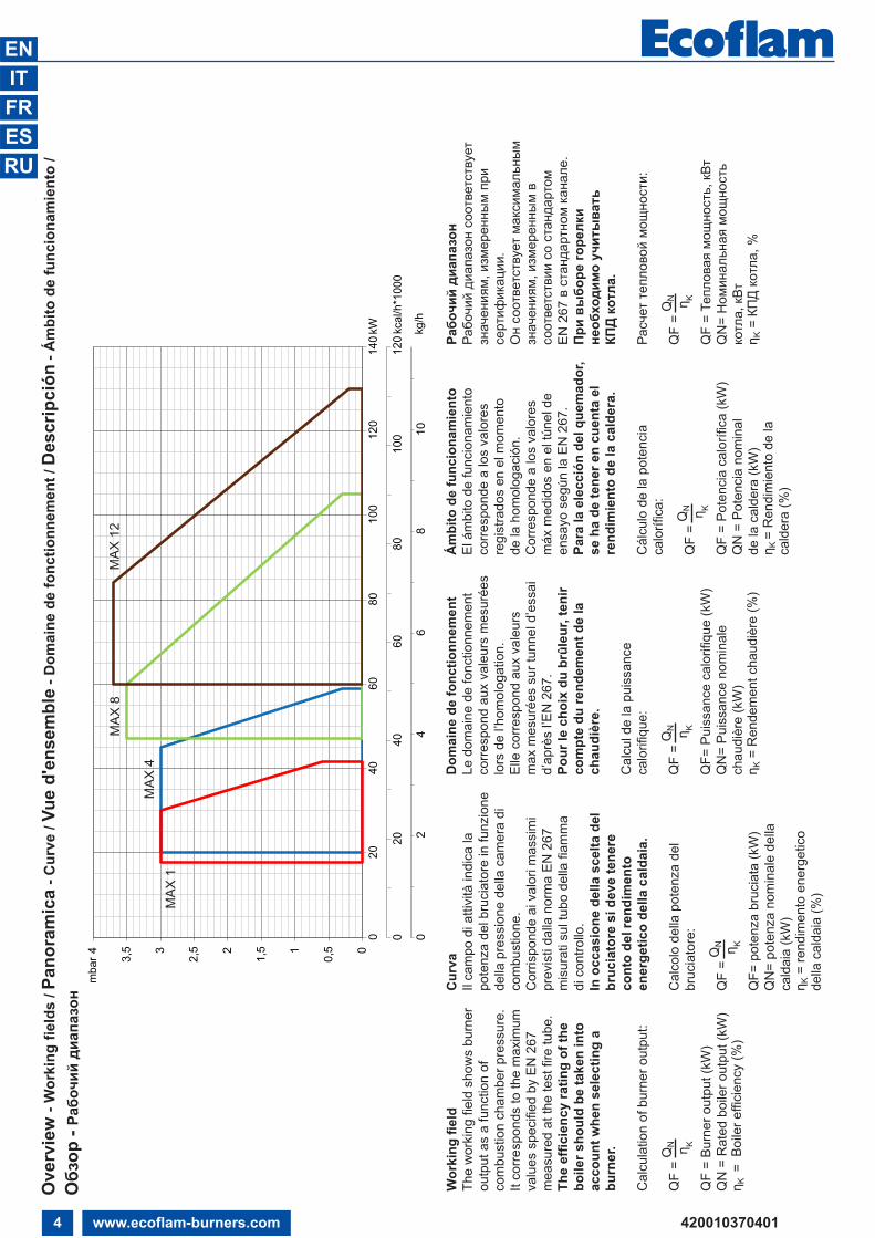
Wor
king
fiel
dTh
e w
orki
ng fi
eld
show
s bu
rner
ou
tput
as
a fu
nctio
n of
co
mbu
stio
n ch
ambe
r pre
ssur
e.
It co
rresp
onds
to th
e m
axim
um
valu
es s
peci
fied
by E
N 2
67
mea
sure
d at
the
test
fire
tube
.Th
e ef
ficie
ncy
ratin
g of
the
boile
r sho
uld
be ta
ken
into
ac
coun
t whe
n se
lect
ing
a bu
rner
.
Cal
cula
tion
of b
urne
r out
put:
QF
= Q
N η KQ
F =
Burn
er o
utpu
t (kW
)Q
N =
Rat
ed b
oile
r out
put (
kW)
η K=
Boi
ler e
ffici
ency
(%)
Cur
vaIl
cam
po d
i atti
vità
indi
ca la
po
tenz
a de
l bru
ciat
ore
in fu
nzio
ne
della
pre
ssio
ne d
ella
cam
era
di
com
bust
ione
. C
orris
pond
e ai
val
ori m
assi
mi
prev
isti
dalla
nor
ma
EN 2
67
mis
urat
i sul
tubo
del
la fi
amm
a di
con
trollo
.In
occ
asio
ne d
ella
sce
lta d
el
bruc
iato
re s
i dev
e te
nere
co
nto
del r
endi
men
to
ener
getic
o de
lla c
alda
ia.
Cal
colo
del
la p
oten
za d
elbr
ucia
tore
:
QF
= Q
N η KQ
F= p
oten
za b
ruci
ata
(kW
)Q
N=
pote
nza
nom
inal
e de
lla
cald
aia
(kW
)η K
= re
ndim
ento
ene
rget
ico
della
cal
daia
(%)
Dom
aine
de
fonc
tionn
emen
tLe
dom
aine
de
fonc
tionn
emen
t co
rresp
ond
aux
vale
urs
mes
urée
s lo
rs d
e l’h
omol
ogat
ion.
Elle
cor
resp
ond
aux
vale
urs
max
mes
urée
s su
r tun
nel d
’ess
ai
d’ap
rès
l’EN
267
.Po
ur le
cho
ix d
u br
ûleu
r, te
nir
com
pte
du re
ndem
ent d
e la
ch
audi
ère.
Cal
cul d
e la
pui
ssan
ce
calo
rifiq
ue:
QF
= Q
N η KQ
F= P
uiss
ance
cal
orifi
que
(kW
)Q
N=
Puis
sanc
e no
min
ale
chau
dièr
e (k
W)
η K=
Ren
dem
ent c
haud
ière
(%)
Ám
bito
de
func
iona
mie
nto
El á
mbi
to d
e fu
ncio
nam
ient
o co
rresp
onde
a lo
s va
lore
s re
gist
rado
s en
el m
omen
to
de la
hom
olog
ació
n.C
orre
spon
de a
los
valo
res
máx
med
idos
en
el tú
nel d
e en
sayo
seg
ún la
EN
267
.Pa
ra la
ele
cció
n de
l que
mad
or,
se h
a de
tene
r en
cuen
ta e
lre
ndim
ient
o de
la c
alde
ra.
Cál
culo
de
la p
oten
cia
calo
rífic
a:
QF
= Q
N η KQ
F =
Pote
ncia
cal
orífi
ca (k
W)
QN
= P
oten
cia
nom
inal
de
la c
alde
ra (k
W)
η K =
Ren
dim
ient
o de
la
cald
era
(%)
Рабочий диапазон
Рабочий диапазон
соответствует
значениям
, измеренным
при
сертификации
.Он соответствует максимальным
значениям
, измеренным
всоответствии
со стандартом
EN
267
в стандартном
канале.
При
выборе
горелки
необходимо учитывать
КПД
котла
.
Расчет
тепловой мощности:
QF
= Q
N η KQ
F = Тепловая
мощность,
кВт
QN
= Номинальная
мощность
котла,
кВт
η K= КПД котла,
%
MAX
4
MAX
12
MAX
8
MAX
1
Ove
rvie
w -
Wor
king
fiel
ds /
Pano
ram
ica
- Cur
ve /
Vue
d'en
sem
ble
- Dom
aine
de
fonc
tionn
emen
t / D
escr
ipci
ón- Á
mbi
to d
e fu
ncio
nam
ient
o /
Обзор
- Рабочий диапазон

5www.ecoflam-burners.com420010370401
ENITFRESRU
Ove
rvie
w -
Dim
ensi
ons
/ Pan
oram
ica
- Dim
ensi
oni /
Vue
d'e
nsem
ble
- Dim
ensi
ons
/ Des
crip
ción
-D
imen
sion
es / Обзор
-Размеры
XY
Z
Pack
agin
g
MAX
1
d..°
Ø a
Ø b
Ø c
125
153
M
MAX
8-1
2
M
d..°
Ø a
Ø b
Ø c
MAX
4
d..°
Ø a
Ø b
Ø c
125
M
MAX
1
CB
A
ED
-D1
FG
M
126
151 I
L
Max
Gas
70P
-120
P
NP
O
MAX
4 -
8 - 1
2
Mod
elA
BC
DD
1E
FG
IL
MM
AX 1
288
143
145
8014
015
389
160
92/1
0792
/107
M8
MAX
429
714
914
890
145
204
8916
090
/107
90/1
07M
8M
AX 8
303
155
148
9014
520
489
160
100/
120
100/
120
M8
MAX
12
317
169
148
100
155
204
9816
010
0/12
010
0/12
0M
8
Mod
elØ
aØ
bØ
cd°
..M
AX 1
100
130
150
45°
MAX
411
012
6,5
151,
545
°M
AX 8
110
140
170
45°
MAX
12
110
140
170
45°
Mod
elX
YZ
KgM
AX 1
310
400
320
7M
AX 4
415
400
310
9M
AX 8
415
400
310
9,5
MAX
12
415
400
310
10
AB
CD
/ D1
E
M
L
FG
125 I
6 www.ecoflam-burners.com
EN
420010370401
Contents - Index - General warnings - Conformity declaration
Important notesThe MAX burners are designed for thecombustion of domestic fuel oil EL inaccordance with EN267 standards.
Assembly, commissioning andmaintenance must be carried out only byauthorised specialists and all applicableguidelines and regulations must beobserved.
Burner descriptionThe MAX burner is a single-stage, fully-automatic monoblock-type burner. It issuitable for use, within its range ofperformance, with boilers complying withEN 303 or hot-air generators in line withDIN 4794, DIN 30697 or EN 621.Use for any other application requires theapproval of Ecoflam.
The following standards should beobserved in order to ensure safe,environmentally sound and energy-efficientoperation:
EN 226Connection of vaporising oil and forceddraught gas burners to the heat generator.
EN 60335-2Safety of electrical equipment for domesticuse.
Installation locationThe burner must not be operated in roomscontaining aggressive vapours (e.g. spray,perchloroethylene, hydrocarbontetrachloride, solvent, etc.) or tending toheavy dust formation or high air humidity.Adequate ventilation must be provided atthe place of installation of the furnacesystem to ensure a reliable supply withcombustion air.Variations may arise as a result of localregulations.
We can accept no warranty liabilitywhatsoever for loss, damage or injurycaused by any of the following:- Inappropriate use.- Incorrect assembly or repair by the
customer or any third party, including thefitting of non-original parts.
Provision of the system and theoperating instructionsThe firing system manufacturer mustsupply the operator of the system withoperating and maintenance instructions onor before final delivery. These instructionsshould be displayed in a prominentlocation at the point of installation of theheat generator, and should include theaddress and telephone number of thenearest customer service centre.
Notes for the operatorThe system should be inspected by aspecialist at least once a year. It isadvisable to take out a maintenancecontract to guarantee regular servicing.
Declaration of conformityfor oil burners
We,Ecoflam Bruciatori S.p.A.declare under our sole responsibilitythat the light oil burners named
MAXconform to the following standards:EN 267: 2010EN 60335-1: 2008EN 60335-2-30: 2006EN 60335-2-102: 2007EN 55014-1: 2008 + A1: 2009EN 55014-2: 1998 + A1: 2001 + A2:2008
These products bear the CE mark in accordance with the stipulations of thefollowing directives:
2006/95/EEC Low Voltage Directive 2004/108/EEC EMC Directive2006/42/EC Machinery directive
Resana, 28th June 2011 M. PANIZZON
Ecoflam burners have been designed and built in compliance with all current regulations and directives. All burners comply to the safety and energy saving operation regulations within the standard of their respective performance range. The quality is guaranteed by a quality and managementsystem certified in accordance with ISO 9001:2008.
Overview Technical data 3Working fields 4Dimensions 5
Contents Index 6General warnings 6Conformity declaration 6Burner description 7
Function General safety functions 8E-BCU OIL control and safety unit 9Oil burner pump 10
Installation Burner assembly 11Electrical connection 12Checks before commissioning 12Oil feeding and suction line 13
Start up Setting data table - air regulation 14Adjusting burner output 15Oil pressure regulation 15
Service Maintenance 16Troubleshooting 17
Overview Electrical diagrams 66-67Spare parts list 68-71

7www.ecoflam-burners.com
EN
420010370401
A1 E-BCU OIL control boxM1 Electric motor for pump and
blower wheelT1 Ignition transformerY Graduated rodY1 Solenoid valve3 Air regulation in the burner head5 Fastening screws for equipment plate9 Wieland socket15 Burner flange16 Release knob102 Fuel-oil pump103B Air regulation113 Air intake
15 14
MAX 4 LN TW TC - 230V/50-60Hz
MAX Light oil
RANGE NAME BY FUEL TYPE
MAX 4 4 kg/h
MODEL SIZE (Gas: kW; Oil: kg/h)
MAX Low NOx Low NOx Class 3 yellow flame (<120 mg/kWh)MAX Standard Class 2-OIL EN267 (<185 mg/kWh)
EMISSION COMBUSTION TYPE
- 1 stageR 1 stage with preheatherTW Thermowatt E-BCU
OPERATION TYPE
TC Short headTL Long head
HEAD TYPE
- Light oilKER KeroseneBIODIESEL BiodieselD Heavy oil: max visc. 50° E at 50°C
FUEL
230V/50-60Hz 230 Volt, 50-60 Hz
ELECTRICAL SUPPLY TO THE SYSTEM
3
113 103B5
Y1
A1
M1 T1
15
16102 9 Y
Contents - Burner description
Scope of deliveryCB: COMPLETE BURNER - 1 bag including :
- multilanguage technical manual.- filter and hoses.- wieland plug.- nozzle and spanner.- screws, nuts and washer.
KIT & ACS delivered separately
8 www.ecoflam-burners.com
EN
420010370401
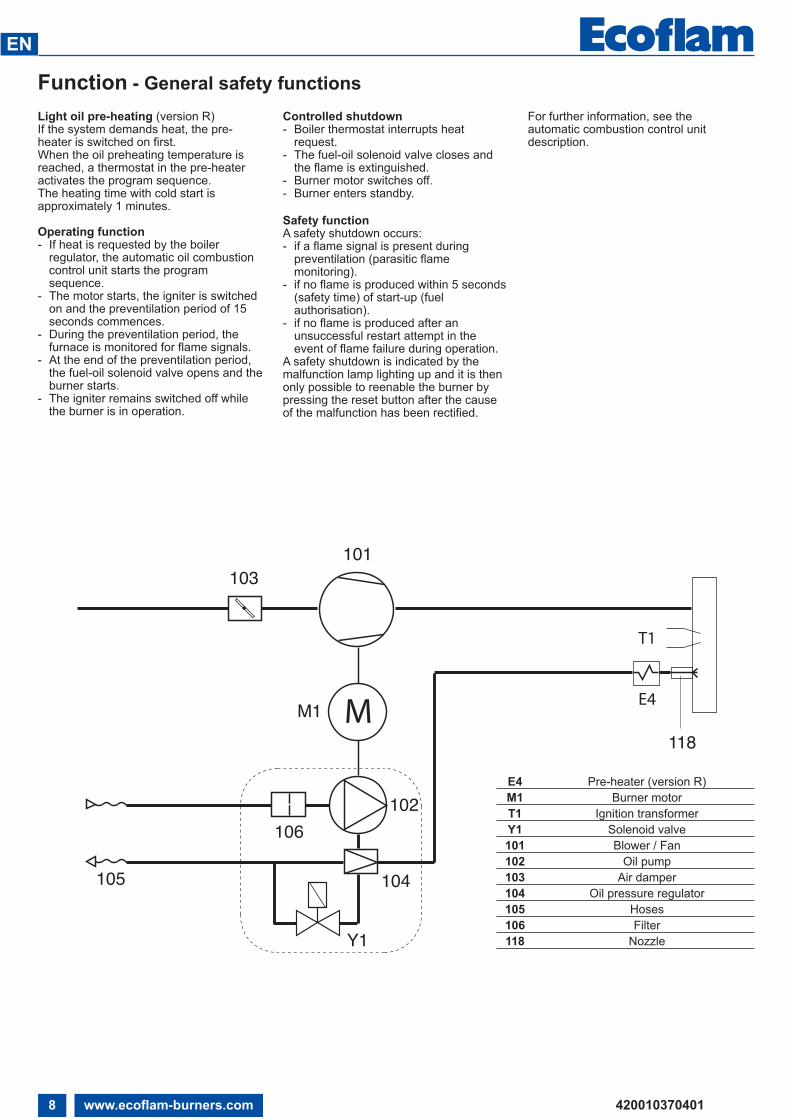
Function - General safety functionsLight oil pre-heating (version R)If the system demands heat, the pre-heater is switched on first.When the oil preheating temperature isreached, a thermostat in the pre-heateractivates the program sequence.The heating time with cold start isapproximately 1 minutes.
Operating function- If heat is requested by the boiler
regulator, the automatic oil combustioncontrol unit starts the programsequence.
- The motor starts, the igniter is switchedon and the preventilation period of 15seconds commences.
- During the preventilation period, thefurnace is monitored for flame signals.
- At the end of the preventilation period,the fuel-oil solenoid valve opens and theburner starts.
- The igniter remains switched off whilethe burner is in operation.
Controlled shutdown- Boiler thermostat interrupts heat
request.- The fuel-oil solenoid valve closes and
the flame is extinguished.- Burner motor switches off.- Burner enters standby.
Safety functionA safety shutdown occurs:- if a flame signal is present during
preventilation (parasitic flamemonitoring).
- if no flame is produced within 5 seconds(safety time) of start-up (fuelauthorisation).
- if no flame is produced after anunsuccessful restart attempt in theevent of flame failure during operation.
A safety shutdown is indicated by themalfunction lamp lighting up and it is thenonly possible to reenable the burner bypressing the reset button after the causeof the malfunction has been rectified.
For further information, see the automatic combustion control unitdescription.
M M1118
103101
E4
T1
104
102106
105
Y1
E4 Pre-heater (version R) M1 Burner motor T1 Ignition transformer Y1 Solenoid valve 101 Blower / Fan 102 Oil pump 103 Air damper 104 Oil pressure regulator 105 Hoses 106 Filter 118 Nozzle
9www.ecoflam-burners.com
EN
420010370401
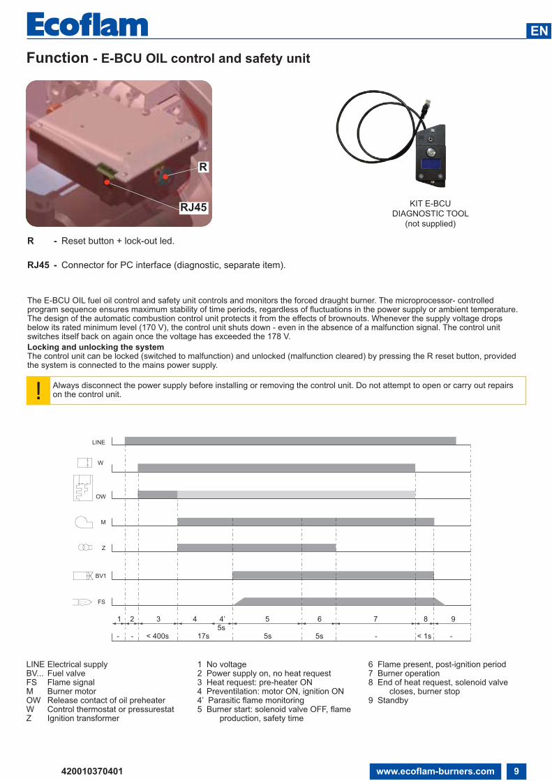
The E-BCU OIL fuel oil control and safety unit controls and monitors the forced draught burner. The microprocessor- controlledprogram sequence ensures maximum stability of time periods, regardless of fluctuations in the power supply or ambient temperature.The design of the automatic combustion control unit protects it from the effects of brownouts. Whenever the supply voltage dropsbelow its rated minimum level (170 V), the control unit shuts down - even in the absence of a malfunction signal. The control unitswitches itself back on again once the voltage has exceeded the 178 V. Locking and unlocking the systemThe control unit can be locked (switched to malfunction) and unlocked (malfunction cleared) by pressing the R reset button, providedthe system is connected to the mains power supply.
R
RJ45
R - Reset button + lock-out led.
RJ45 - Connector for PC interface (diagnostic, separate item).
W
OW
M
Z
BV1
FS
LINE
1
< 400s 17s 5s5s
5s --- -< 1s
2 3 4 4’ 5 6 7 8 9
LINE Electrical supplyBV... Fuel valveFS Flame signalM Burner motorOW Release contact of oil preheaterW Control thermostat or pressurestatZ Ignition transformer
1 No voltage2 Power supply on, no heat request3 Heat request: pre-heater ON4 Preventilation: motor ON, ignition ON4’ Parasitic flame monitoring5 Burner start: solenoid valve OFF, flame production, safety time
6 Flame present, post-ignition period7 Burner operation8 End of heat request, solenoid valve closes, burner stop9 Standby
! Always disconnect the power supply before installing or removing the control unit. Do not attempt to open or carry out repairs on the control unit.
Function - E-BCU OIL control and safety unit
KIT E-BCUDIAGNOSTIC TOOL
(not supplied)

10 www.ecoflam-burners.com
EN
420010370401
Function - Oil burner pump1 suction intake connection.2 return connection.3 pressure connection.4 oil pressure gauge connection.5 negative pressure gauge connection.6 oil pressure regulator.10 Solenoid valve electrical connection.Y1 fuel-oil solenoid valve.6
1 2
3
45
Y1 10
P V
SUNTEC AS V 47 A
2 1
4
5
6P
- + V
P
3
10Y1
DANFOSS BFP 21 R3
The oil burner pump used is a self-priminggear pump, which must be connected astwo-line pump via a bleed filter. There is anintake filter and an oil pressure regulatorintegrated in the pump. Pressure gaugesfor pressure measurements and negativepressure measurements must beconnected before the equipment iscommissioned.
NB: before starting the burner, check thatthe return pipe is open. An eventualobstraction could damage the pumpsealing device.
321 1321
1
1 Hoses2 Filter3 Oil cock 4 Plug5 By-pass plug
5
4
One-pipe system ONE PIPE SYSTEM: If the oil supplycircuit is one-pipe system, the pumpneeds to be modified following intructionsin the picture.
321 321
SUNTEC
DANFOSS
SUNTEC
DANFOSS

11www.ecoflam-burners.com
EN
420010370401
Installation - Burner assembly
Oil connectionThe filter must be located in such a waythat the correct hose routing cannot beimpaired. The hoses must not kink.
Burner assemblyThe burner is fixed by mean of connectingflange and therefore to the boiler.
Installation:• To fix the flange 3 to the boiler with
the screws 4.• Turn the burner slightly, guide it into
the flange and secure using screw 5.
Removal:• Loosen screw 5.• Turn the burner out and pull it out of
the flange.
Burner pipe insertion depth and brickworkUnless otherwise specified by the boiler manufacturer, heat generators without a cooled front wall require brickwork or insulation 5 as shown in the illustration. The brickwork must not protrude beyond the leading edge of the flame tube, and should have a maximum conical angle of 60°. Gap 6 must be filled with an elastic, non-combustible insulation material. For boilers with reverse firing, the minimum burner tube insertion depth A as specified in the boiler manufacturer’s instructions must be observed.
Exhaust systemTo avoid unfavourable noise emissions, right-angled connectors should not be used on the flue gas side of the boiler.
1
34 –
+
2
35

12 www.ecoflam-burners.com
EN
420010370401
Installation - Electrical connection - Checks before commissioning
Electrical connectionThe electrical installation and connectionwork must only be carried out by anauthorised electrical specialist.All applicable rules and regulations mustbe observed.The electrical installation should include atype A circuit breaker.The applicable guidelines anddirectives must be observed, as well asthe electrical circuit diagram suppliedwith the burner!
• Check to ensure that the power supplyvoltage is as specified in the electricdiagram and in data plate.
• Burner fuse: 5 A.
Checks before commissioningThe following must be checked before initial commissioning:• That the burner is assembled in accordance with the instructions givenhere.• That the burner is pre-set in accordancewith the values in the adjustment table.• Setting the combustion components.• The heat generator must be ready foroperation, and the operating regulationsfor the heat generator must be observed.• All electrical connections must be correct.• The heat generator and heating system
must be filled with water and thecirculating pumps must be in operation.• The thermostats, pressure regulator, lowwater detectors and any other safety orlimiting devices that might be fitted mustbe connected and operational.• The exhaust gas duct must beunobstructed and the secondary airsystem, if available, must be operational.• An adequate supply of fresh air must beguaranteed.• The heat request must be available.• Fuel tanks must be full.• The fuel supply lines must be
assembled correctly, checked for leaksand bled.• A standard-compliant measuring pointmust be available, the exhaust gas ductup to the measuring point must be free ofleaks to prevent anomalies in themeasurement results.
1
Input Voltage
S3B4 T2 NT1 L1
T P
STC
PE
N
L
Q
HLF HLBT P
STS
Electrical connection (plug-in)It must be possible to disconnect theburner from the mains using anomnipolar shutdown device complyingwith the standards in force. The burnerand heat generator (boiler) are connectedby a 7-pin connector (fig.1).
Position of electrodesNote: Always check the position ofelectrodes after having replaced thenozzle (see illustration). A wrong positioncould cause ignition troubles.
3 mm
5/6 mm
4 mm

13www.ecoflam-burners.com
EN
420010370401
Installation - Oil feeding and suction line
H
H (m)
ø 6 mm ø 10 mm
0,51
1,52
2,53
3,5
151311975-
100998468533722
H (m)
ø 6 mm ø 10 mm0,51
1,52
2,53
3,5
19212325272931
ø 8 mm
4741342822159
ø 8 mm60667279859198
100100100100100100100
H = x-y
y
x
Two-pipe siphon feed system
Two-pipe lift systemLength pipe (m)
Length pipe (m)
FEEDING LINE WITH DANFOSS BFP21 R3
H
H (m) ø 8 mm ø 10 mm0,51
1,52
2,53
3,5
30354045505560
65707580859095
H (m)
ø 8 mm ø 10 mm0,51
1,52
2,53
3,5
232119171494
55504540342822
y
xH = x-y
Two-pipe siphon feed system
Two-pipe lift system Length pipe (m)
Length pipe (m)
FEEDING LINE WITH SUNTEC AS V 47 A

14 www.ecoflam-burners.com
EN
420010370401
Start up - Setting data table - Air regulation
The settings above are basic settings.These adjustment values are normallysuitable for commissioning the burner.These values have been determined in our test labs and are useful for the first
switch-on as final setting must be doneusing a combustion analyzer.Favourable combustion values can beachieved using the following nozzles:
DANFOSS H÷S 80°÷60°DELAVAN W 60°STEINEN S 60°
NOZZLE PUMP OUTPUT FIRING HEAD SETTING AIR DAMPER SETTING gph spry bar kg/h Pos. Pos. 0,40 60°S 12 1,6 0 1,8 0,50 60°S 12 2 0,3 2,3 0,55 60°S 12 2,3 0,5 3 0,60 60°S 12 2,4 1 3,5 0,65 60°S 12 2,7 1,5 4,5 0,75 60°S 12 3,1 2 5,3 0,85 60°S 12 3,5 2,5 6,5 0,50 60°S 12 2 0 3 0,60 60°S 12 2,4 0,5 4 0,65 60°S 12 2,7 0,5 5 0,75 60°S 12 3,1 1 6,3 0,85 60°S 12 3,5 3 8 1,00 60°S 12 4,35 4 10 1,00 60°S 12 4,35 1 4 1,10 60°S 12 4,5 1 5,5 1,25 60°S 12 5 2 6,2 1,35 60°S 12 5,6 2,5 7,3 1,50 60°S 12 6,2 3,5 8,5 1,65 60°S 12 7 4 9,2 1,75 60°S 12 7,6 4,5 10,5 1,50 60°S 12 6,2 0 2 1,65 60°S 12 7 1 3,5 1,75 60°S 12 7,6 2 5 2,00 60°S 12 8,3 3 7 2,25 60°S 12 9,3 3,5 8,5 2,50 60°S 12 10,4 4 9,5 2,75 60°S 12 11,5 4,5 10,5
MA
X 4
MA
X 12
MA
X 8
MA
X 1
+
-
A Air damper setting (A).To act on the screw in figure: • to increase output, turn screwdriver
clockwise• to reduce output, turn screwdriver
counterclockwise
Firing head setting (B).To act on the screw in figure:• turn Allen key till you reach the
requested value (index 0-4,5).
+-
A MAX 1 MAX 4-8-12
+-
+-
B
+-
+-
B
MAX 1 MAX 4-8-12

6
1 2
3
45
Y1 10
SUNTECSUNTEC
P V
15www.ecoflam-burners.com
EN
420010370401
Start up - Adjusting burner output - Oil pressure regulation
Burner startBefore starting the burner, draw oil in untilthe filter is completely filled.Then start the burner by switching on theboiler regulator. Open the bleed screw onthe oil filter to allow the oil line to bleedfully during the preventilation phase. Thenegative pressure must not fall below 0.4bar. Close the bleed screw when the filteris completely filled with oil and oil isflowing out without bubbles.
Burner output adjustmentUse the pressure regulator to adjust the oilpressure in accordance with the burner output desired. Monitor the combustion values continuously as you do so (CO,CO2, soot test). Adjust the airflow gradually if necessary.
1 suction intake connection.2 return connection.3 pressure connection.4 oil pressure gauge connection.5 negative pressure gauge connection.6 oil pressure regulator.10 Solenoid valve electrical connection.Y1 fuel-oil solenoid valve.
SUNTEC AS V 47 A
2 1
4
5
6P
- + V
P
3
10Y1
DANFOSS BFP 21 R3
Optimising combustion valuesIf the combustion values are notsatisfactory modify the position of thecombustion head. By doing this the burnerignition conditions and the combustionvalues change. Compensate for thechange in airflow if necessary by adjustingthe air flap position.
Note: observe the minimum requiredflue gas temperature specified by theboiler manufacturer and therequirements demanded of flue gasducts for avoiding condensation.
Oil pressure regulationThe oil pressure, and therefore burneroutput, is adjusted using oil pressureregulator 6 in the pump. Turn to- right: to increase pressure- left: to reduce pressureConnect a pressure gauge at point 4 (withR1/8" thread).
Checking negative pressureThe vacuum meter for checking negativepressure must be connected to point 5,R1/8". Maximum permissible negativepressure is 0.4 bar. At higher negativepressures, the fuel oil gasifies, whichcauses scraping noises in the pump andultimately leads to pump damage.
Cleaning the pump filterThe filter is located under the pumpcover(SUNTEC) or in appropriatecartridge(DANFOSS). To be able to cleanthe filter, it is necessary to loosen thescrews and remove the cover first(SUNTEC) or to unscrew the screw(DANFOSS).• Check the pump cover seal and replace
the gasket if necessary.
Operating checkFlame monitoring must be checked forsafety as part of initial commissioning andalso after servicing or if the system hasbeen out of operation for any significantperiod of time.
- Starting attempt with flame monitor unlit:the automatic combustion control unitmust switch to malfunction at the end ofthe safety time
- Start with flame monitor lit: the automatic combustion control unit must switch to malfunction after 10 seconds of preventilation
- Normal start-up: flame monitor goes outwhen burner in operation; the automaticcombustion control unit must switch tomalfunction after the restart and end ofthe safety time
!Risk of air blast!Continuously check CO, CO2 and soot emissions when adjusting the output ofthe burner. Optimise combustion values in the event of CO formation. CO mustnot exceed 50 ppm.

16 www.ecoflam-burners.com
EN
420010370401
Service - Maintenance
+
–
Fan assemblyObserve the positioning diagram belowwhen replacing the motor and blowerwheel. The inside flange A of the blowerwheel must be fitted at the same level asthe equipment plate B. Insert a straightedge between the wing of the blower wheeland set A and B to the same height, tightenthe set screw on the blower wheel(maintenance position 1).
Burner and boiler servicing must onlybe carried out by qualified personell.The system operator is advised to takeout a service contract to guaranteeregular servicing.
Attention• Disconnect the electrical supply before
carrying out any maintenance orcleaning work.
• The blast tube and firing head may behot.
Checking the exhaust gas temperature• Check the flue gas temperature at
regular intervals.• Clean the boiler if the flue gas
temperature is more than 30°C abovethe value measured at the time ofcommissioning.
• To simplify the check, use a flue gastemperature indicator.
Burner maintenance positions• After removing the screws 5 turn theburner and pull it out of the flange. It ispossible to fix the burner in three positions
for maintenance.
Position 1Maintenance line air (cleaning/substitution fan)Position 2Burner head maintenance.Position 3Maintenance components (filter and lightoil pump).
Maintenance on the burner
Maintenance position 1• Clean fan and housing and check for
damage.Maintenance position 2• Check and clean the combustion head.• Replace oil nozzle.• Check ignition electrodes, readjust or
replace as necessary.• Fit combustion head. Observe
adjustment dimensions.• Fit burner.• Start burner, check flue gas data, correct
burner settings if necessary.Maintenance position 3• Check oil supply components (tubes,
pumps, oil feed tube) and theirconnections for leaks or signs of wear,replace if necessary.
• Check electrical connections andconnection cables for damage, replace ifnecessary.
• Check pump filter and clean ifnecessary.
1 2 3
Nozzle and cleaning replacementUse only the suitable box wrench providedfor this operation to remove the nozzle,taking care to not damage the electrodes.Fit the new nozzle by the same care. Note: Always check the position ofelectrodes after having replaced thenozzle (see illustration). A wrong positioncould cause ignition troubles.
Max 1
Max 4-8-12
–+
2
35

17www.ecoflam-burners.com
EN
420010370401
Fault diagnosis and repairIn the event of a malfunction, first checkthat the prerequisites for correct operationare fulfilled:1. is the system connected to the powersupply?2. is there oil in the tank?3. are all shut-off valves open?4. are all control and safety devices,such as the boiler thermostat, low-waterdetector, limit switch, etc.adjusted correctly?If the malfunction persists, use thefollowing table.It is not permitted to repair anycomponents relevant to safety. These
components must be replaced by partswith the same order number.
Only use original spare parts.
NB: after each operation:• under normal operating conditions(doors closed, hood fitted, etc.), checkcombustion and check the individuallines for leaks.• Record the results in the relevantdocuments.
E-BCU display interface must be usedto read the faults by service personell.
Service - Troubleshooting
Fault Symbol fault Cause Remedy
No heat request Thermostats defective or incorrectly adjusted Adjust the thermostats, replace if necessary.
Burner does not start after thermostat shutdown.No malfunction indicated on the automatic combustion control unit.
Drop in supply voltage or power failure.Control unit malfunction
Check the cause of the fall in voltage or thepower failure.Replace the control unit.
Burner starts at switch-on for very short period andthen shuts down and the redLED lights up
The control unit has been intentionally locked Reset control unit.
Burner starts and then shuts down afterpreventilation
Flaring during pre-ventilation orpre-ignition
Check ignition sparks/adjust or replaceelectrodeCheck/replace fuel-oil solenoid valve
Burner starts and then shutsdown after the solenoidvalves have opened
No flame signal at end of safety time
Check the oil level in the tank.Top tank up as required.Open the valves.Check the oil pressure and the operation ofthe pump, coupling, filter, solenoid valve.Check ignition circuit, electrode adjustment.Clean/replace electrodes.Clean/replace flame monitor.Replace the following items as required:Ignition electrodes/ignition cables/ignition transformer/nozzle/pump/solenoid valve/automatic combustion control unit.
Flame extinguishing during operation
Flame goes out during operating phase
66 www.ecoflam-burners.com 420010370401
ENITFRESRU
ELEC
TROV
ALVU
LA D
E GAS
OLEO
ELCT
ROVA
NNE M
AZOU
T OI
L SOL
ENOI
D VAL
VE
ELET
TROV
ALVO
LA G
ASOL
IO
YVg
STS
STC
HLB
TV
TERM
OSTA
TO D
E SEG
URID
ADTH
ERMO
STAT
DE S
ECUR
ITESA
FETY
THER
MOST
AT
TRAN
SFOR
MATE
UR D
'ALLU
MAGE
IGNI
TION T
RANS
FORM
ER
TERM
OSTA
TO CA
LDER
ATH
ERMO
STAT
CHAU
DIER
E
TERM
OSTA
TO D
I SICU
REZZ
A
TERM
OSTA
TO CA
LDAI
A
LAMP
E DE S
ECUR
ITE
BOILE
R THE
RMOS
TAT
ESPIA
DE B
LOQU
EO
TRAN
SFOR
MADO
R
LOCK
-OUT
LAMP
LAMP
ADA D
I BLO
CCO
TRAS
FORM
ATOR
E
MVQB
FOTO
RESIS
TENC
IA
INTE
RRUP
TOR G
ENER
AL CO
N FU
SIBLE
INTE
RRUP
TEUR
GEN
ERAL
AVEC
FUSIB
LEMA
IN SW
ITCH W
ITH FU
SEIN
TERR
UTTO
RE G
ENER
ALE C
ON FU
SIBILE
MOTO
R VEN
TILAD
ORMU
TEUR
VENT
ILATE
URMO
TOR F
ANMO
TORE
VENT
ILATO
RE
PHOT
ORES
ISTAN
CEPH
OTO-
RESIS
TOR
FOTO
RESIS
TENZ
A
TVB
YVg
M1
MV
HLF
LAMP
ADA D
I FUN
ZIONA
MENT
OW
ORKIN
G LA
MPLA
MPE D
E FON
CTIO
NNEM
ENT
ESPIA
DE F
UNCIO
NAMI
ENTO
CN01
CN02
CN03
CN08
CN07
MODE
LLO
/ MOD
EL
50Hz
220
V/24
0V
50/6
0 Hz
220V
/240
V
MAX 1
5-20-3
0
MAX 1
-4-8-1
2
ALIM
ENTA
ZIONE
/ POW
ER SU
PPLY
Tens
ione d
i alim
entaz
ione /
Inpu
t Volt
age
Input
Volta
ge
11
11
1
ZFIL
TRO
ANTID
ISTUR
BO
ANTJA
MMIN
G FIL
TER
FILTR
E ANT
IPARA
SITES
FIL
TRO
DE PT
OTEC
ION
ANTID
ISTUR
BIO
Z
S3B4
T2N
T1L1
S3B4
T1T2
NL1
TP
STC
PE NL
Q
HLF
HLB
TP
STS
THER
MO
WAT
T E-
BCU
OIL
TOT.
SHEE
T
SHEE
TDE
SIGNE
RDE
SCRIP
TION
DATE
FIST
CREA
TION
CODE
SIGNA
TURE
R&D
DEPA
RTME
NT
CONT
ROLL
EREc
oflam
Bru
ciat
ori
SERV
OMOT
OR
FLAM
E SEN
SOR
S.p.
AEC
N FIR
ST CR
EATIO
N
BY TERM LAWS WE RESERVED THE PROPERTY OF THIS WIRING DIAGRAM WITH PROHIBITION OF USE AND REPRODUCTION
LEAK
AGE C
ONTR
OL
CONT
ROL B
OX
DATE
ECN
MODI
CATIO
NMO
DIFIC
ATIO
N DE
SCRIP
TION
ECN
MODI
FICAT
ION
MAX 1
-4-8-1
2-15-2
0-30
A.POZ
ZOBO
N
24-09
-2010
1
4201
1004
2301
1 A
.RIGO
NI
B
RBA1
0NP0
09TH
ERMO
WATT
E-BC
U OI
L
20-04
-2011
RBA1
1PM0
12
F
1
ED
23
4
CBA
12
34
56
78
FED
56
7
CB
8
A
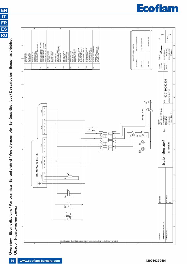
Ove
rvie
w -
Elec
tric
diag
ram
s / P
anor
amic
a- S
chem
i ele
ttric
i / V
ue d
'ens
embl
e- S
chém
as é
lect
rique
/ Des
crip
ción
- Esq
uem
as e
léct
rico
/Обзор
- Электрические
схемы

67www.ecoflam-burners.com420010370401
ENITFRESRU
ELEC
TROV
ALVU
LA D
E GAS
OLEO
EL
CTRO
VANN
E MAZ
OUT
OIL S
OLEN
OID V
ALVE
EL
ETTR
OVAL
VOLA
GAS
OLIO
YV
g
STS
STC
HLB
TV
TERM
OSTA
TO D
E SEG
URID
ADTH
ERMO
STAT
DE S
ECUR
ITESA
FETY
THER
MOST
AT
TRAN
SFOR
MATE
UR D
'ALLU
MAGE
IGNI
TION T
RANS
FORM
ER
TERM
OSTA
TO CA
LDER
ATH
ERMO
STAT
CHAU
DIER
E
TERM
OSTA
TO D
I SICU
REZZ
A
TERM
OSTA
TO CA
LDAI
A
LAMP
E DE S
ECUR
ITE
BOILE
R THE
RMOS
TAT
ESPIA
DE B
LOQU
EO
TRAN
SFOR
MADO
R
LOCK
-OUT
LAMP
LAMP
ADA D
I BLO
CCO
TRAS
FORM
ATOR
E
MVQB
FOTO
RESIS
TENC
IA
INTE
RRUP
TOR G
ENER
AL CO
N FU
SIBLE
INTE
RRUP
TEUR
GEN
ERAL
AVEC
FUSIB
LEMA
IN SW
ITCH W
ITH FU
SEIN
TERR
UTTO
RE G
ENER
ALE C
ON FU
SIBILE
MOTO
R VEN
TILAD
ORMU
TEUR
VENT
ILATE
URMO
TOR F
ANMO
TORE
VENT
ILATO
RE
PHOT
ORES
ISTAN
CEPH
OTO-
RESIS
TOR
FOTO
RESIS
TENZ
A
TVB
YVg
M1
MV
HLF
LAMP
ADA D
I FUN
ZIONA
MENT
OW
ORKIN
G LA
MPLA
MPE D
E FON
CTIO
NNEM
ENT
ESPIA
DE F
UNCIO
NAMI
ENTO
CN01
CN02
CN03
CN08
CN07
MODE
LLO
/ MOD
EL
50/6
0 Hz
220V
/240
VMA
X 1R -
4R
ALIM
ENTA
ZIONE
/ POW
ER SU
PPLY
Tens
ione d
i alim
entaz
ione /
Inpu
t Volt
age
Input
Volta
ge
11
11
1
STCA
R
TERM
OSTA
TO CO
NSEN
SO AC
CENS
IONE
MAIN
OIL
TANK
THER
MAST
ATTH
ERMO
STAT
CONS
ENT.
ALLU
MAGE
TERM
OSTA
TO D
E ENC
ENDI
DO
RESIS
TENZ
APR
E-HEA
TER
RESIS
TANC
EPR
ECAL
ENTA
DOR
ZFIL
TRO
ANTID
ISTUR
BOAN
TJAMM
ING
FILTE
RFIL
TRE A
NTIPA
RASIT
ES
FILTR
O DE
PTOT
ECIO
N AN
TIDIST
URBIO
Z
S3B4
T2N
T1L1
S3B4
T1T2
NL1
TP
STC
PE NL
Q
HLF
HLB
TP
STS
THER
MO
WAT
T E-
BCU
OIL
TOT.
SHEE
T
SHEE
TDE
SIGNE
RDE
SCRIP
TION
DATE
FIST
CREA
TION
CODE
SIGNA
TURE
R&D
DEPA
RTME
NT
CONT
ROLL
EREc
oflam
Bru
ciat
ori
SERV
OMOT
OR
FLAM
E SEN
SOR
S.p.
AEC
N FIR
ST CR
EATIO
N
BY TERM LAWS WE RESERVED THE PROPERTY OF THIS WIRING DIAGRAM WITH PROHIBITION OF USE AND REPRODUCTION
LEAK
AGE C
ONTR
OL
CONT
ROL B
OX
DATE
ECN
MODI
CATIO
NMO
DIFIC
ATIO
N DE
SCRIP
TION
ECN
MODI
FICAT
ION
MAX 1
R - 4R
A.POZ
ZOBO
N
25-02
-2011
1
4201
1005
2901
1 A
.RIGO
NI
B
RBA1
0NP0
09TH
ERMO
WATT
E-BC
U OI
L
20-04
-2011
RBA1
1PM0
12
F
1
ED
23
4
CBA
12
34
56
78
FED
56
7
CB
8
A
R
PT
STCA
Ove
rvie
w -
Elec
tric
diag
ram
s / P
anor
amic
a- S
chem
i ele
ttric
i / V
ue d
'ens
embl
e- S
chém
as é
lect
rique
/ Des
crip
ción
- Esq
uem
as e
léct
rico
/Обзор
- Электрические
схемы

68 www.ecoflam-burners.com 420010370401
ENITFRESRU
MAX
1
19
2 3
46
1312
1
910
11
8
2930
3328
2526
22
2723
17
20
18
34
34 3515
16
14
31
Ove
rvie
w -
Spar
e pa
rts
list/
Pan
oram
ica
- Par
ti di
rica
mbi
o / V
ue d
'ens
embl
e- P
ièce
s de
rech
ange
/ Des
crip
ción
- Pie
zas
de re
cam
bio
/ Обзор
- Запчасти

69www.ecoflam-burners.com420010370401
ENITFRESRU
20
4
2 3 1
6
17
910
14
8
2722
28
2526
19
MAX
4 - M
AX 8
- MAX
12 24
18
MAX
8M
AX 1
2
30 29
23
21
24
27
2825
2622
32
MAX
8-1
2
MAX
12
33
36
35
36
65
13
12
11
1615
34
37
Ove
rvie
w -
Spar
e pa
rts
list/
Pan
oram
ica
- Par
ti di
rica
mbi
o / V
ue d
'ens
embl
e- P
ièce
s de
rech
ange
/ Des
crip
ción
- Pie
zas
de re
cam
bio
/ Обзор
- Запчасти

70 www.ecoflam-burners.com 420010370401
ENITFRESRU
MAX
1MA
X 1R
n°De
scrip
tion
Desc
rizion
eDé
signa
tion
Desc
ripció
n)А"56)О8А)"6
code
code
1OI
L PUM
P PO
MPA
PO
MPE
COM
PLET
EPO
MPA
)А9О9
6532
5015
6532
5015
2CO
ILBO
BINA
BOBI
NE E
LECT
ROVA
NNE
BOBI
NA$А,У&$А
DANF
OSS
6532
3773
6532
3773
SUNT
EC65
3237
6765
3237
673
OIL V
ALVE
VALV
OLA
VANN
EVA
LVUL
A$'
А;А)
DANF
OSS
6532
3751
6532
3751
SUNT
EC65
3237
4465
3237
444
COUP
LING
GIUN
TOJO
INT
D'AC
COUP
LEM
ENAC
OPLA
MIE
NTO
5У*
,А65
3229
2065
3229
205
NIPP
LERA
CCOR
DO P
ER F
LESS
IBIL
EM
AMEL
ONS
TUER
CA*",")! <'Я !"#$
. &'А)!А
--
6HO
SES
TUBO
FLE
SSIB
ILE
FLEX
IBLE
SLA
TIGU
ILLO
S!"#$"%
&'А)!
PARI
GI N
W 4
MG
6532
3216
6532
3216
7FI
LTER
FILT
ROFI
LTRE
FILT
RO*"'Ь,-
ART.7
0451
-006
AV65
3250
4665
3250
468
COVE
RCO
PERC
HIO
COUV
ERCL
ETA
PA$->&$А
6532
0569
6532
0569
9M
OTOR
MOT
ORE
MOT
EUR
MOT
OR<8"!А,6'Ь
75 W
AEG
6532
2868
6532
2868
10CA
PACI
TOR
COND
ENSA
TORE
COND
ENSA
TEUR
COND
ENSA
DOR
$О)<6)9А,О-
3 µF
AEG
6532
1857
6532
1857
5 µF
SIM
EL65
3250
3865
3250
3811
IGNI
TION
TRA
NSFO
RMER
TRAS
FORM
ATOR
ETR
ANSF
ORM
ATEU
RTR
ANSF
ORM
ADOR
,-А)9*О-5
А,О-
6532
3257
6532
3257
12SU
PPOR
TSU
PPOR
TOSU
PPOR
TSO
PORT
E;О<<6-?$А
6532
5251
6532
5251
13CO
NTRO
L BOX
WIT
H CA
BLES
APPA
RECC
HIAT
URA
CON
CAVI
COFF
RET
DE S
ECUR
ITE
AVEC
CAB
LEEQ
UIPO
CON
TROL
LLA
MA
CON
CABL
ES$О
),-О'Ь)АЯ
А;;А-А,У-А 9
$А#6'
Я5"
THER
MOW
AT E
-BCU
OIL
6532
5255
6532
5255
14PH
OTOR
ESIS
TOR
FOTO
RESI
STEN
ZACE
LLUL
EFO
TORR
ESIS
TENC
IA*О,О-6@"9,О-
SATR
ONIC
6532
0083
6532
0083
15SO
CKET
WIE
LAND
PRES
A W
IELA
NDFI
CHE
FEM
ELE
WIE
LAND
TOM
A W
IELA
ND-А@Ъ
65 W
IELA
ND
6532
2070
6532
2070
16PL
UG W
IELA
NDSP
INA
WIE
LAND
FICH
E M
ALE
WIE
LAND
ESPI
NA W
IELA
ND8"'$А
WIE
LAN
D65
3220
6965
3220
6917
FAN
VENT
OLA
TURB
INE
VENT
ILAD
OR86),"'Я,О-
120
x 42
6532
3826
6532
3826
18AI
R DA
MPE
RSE
RRAN
DARE
GLAG
E D'
AIR
SORT
IERE
GIST
RO A
IRE
<6*
'6$,О-
6532
0523
6532
0523
19OR
ING
GUAR
NIZI
ONE
ORIN
GOR
ING
У;'О,)",6'Ь)АЯ
;-О
$'А<
$А65
3210
6665
3210
6620
COVE
R AI
R IN
LET
CUFF
IAVO
LET
D'AI
RCI
ERRE
EN
ASPI
RACI
ÓN8О
@<УBО@А#О
-65
3205
2265
3205
2221
CABL
ESCA
VI A
CCEN
SION
ECA
BLE
HTCA
BLES
;-О
8О<А -О
@?"!А
TC65
3252
5265
3252
52TL
6532
5253
6532
5253
22EL
ECTR
ODES
ELET
TROD
IEL
ECTR
ODE
ELEC
TROD
OSЭ'6$,-О<>
6532
0924
6532
0924
23BL
AST
TUBE
BOCC
AGLI
OGU
EULA
RDTU
BO L
LAM
A9,А$А)
TC65
3203
3365
3203
33TL
6532
0339
6532
0339
24FI
RING
HEA
DTE
STA
DI C
OMBU
STIO
NETE
TE D
E CO
MBU
STIO
NCA
BEZA
DE
COM
BUST
IÓN
О!)68АЯ
!О'О8$А
TC TL25
NOZZ
LE H
OLDE
R SU
PPOR
TCR
OCIE
RASU
PPOR
T PO
RTE
GICL
EUR
SOPO
RTE
PORT
AINY
ECTO
R$-69,О8")А
TC65
3206
9565
3206
98TL
6532
0699
6510
8818
26NO
ZZLE
HOL
DER
PORT
A UG
ELLO
PORT
E GI
CLEU
RPO
RTAI
NYEC
TOR
<6-?А,6'
Ь *О-9У)$"
TC65
3207
08-
TL65
3207
10-
FPHB
3 D
ANFO
SS-
6532
3009
27DI
FFUS
ERDI
FFUS
ORE
DEFL
ECTE
URDI
FUSO
R-А996$А,6'
Ь65
3207
6065
3207
6028
ROD
ASTA
DI R
EGOL
AZIO
NE T
ESTA
SUPP
ORT
SOPO
RTE
CABE
ZA D
E CO
MBU
STIÓ
N-6!У'"-О
8ОD)
>%
&,О$ О!)68О%
!О'О8$"
TC65
3240
5665
3240
57TL
6532
0204
6510
8820
29FL
ANGE
FLAN
GIA
BRID
EBR
IDA
*'А)6E
6532
0973
6532
0973
30GA
SKET
GUAR
NIZI
ONE
BRUC
IATO
REJO
INT
DE B
RULE
URJU
NTA
;-О
$'А<
$А !О-6'$"
6532
1110
6532
1110
31AN
TIJA
MM
ING
FILT
ERFI
LTRO
ANT
IDIS
TURB
OFI
LTRE
ANT
IPAR
ASIT
ESFI
LTRO
ANT
ITRA
STOR
NO*"'Ь,- ;О<А8'6)"Я ;О56B
32RE
AR D
ISC
DISC
O PO
STER
IORE
DISQ
UE P
OSTE
RIEU
RDI
SCO
POST
ERIO
R@А<)"%
<"9$
--
33FA
N SC
OOP
DEFL
ETTO
REVO
LET
FIXE
SOPO
RTE
<6*
'6$,О-
TC65
3205
0565
3205
05TL
6532
0506
6532
0506
34PI
PE G
ASKE
TGU
ARNI
ZION
E TU
BOJO
INT
DE T
UYAT
ERIE
JUNT
A DE
TUB
O)А#"8$А ,-У#>
6532
1065
6532
1065
35PI
PETU
BOTU
YATE
RIE
TUBO
,-У#А
6532
1508
6532
1508
TC=
Testa
corta
/ Sh
ort H
ead
/ Tet
e co
urte
/ Ca
beza
corta
/ !О
#О$!
АЯ О'(
)*АЯ
'О+О
*!А
TL=
Testa
lung
a / L
ong
Head
/ Tet
e lon
gue
/ Cab
eza
larga
/ ,+-
((АЯ
О'(
)*АЯ
'О+О
*!А
R= V
ersio
ne p
reris
cald
ata /
Ver
sion
pre-
heat
er / V
ersio
n re
chau
ffeur
/ Ver
sion
con
prec
alent
ador
/ .О,)+
Ь 0 1#
),*А
#-$)
+Ь(2
. 1О,О'#
)*О.
Ove
rvie
w -
Spar
e pa
rts
list/
Pan
oram
ica
- Par
ti di
rica
mbi
o / V
ue d
'ens
embl
e- P
ièce
s de
rech
ange
/ Des
crip
ción
- Pie
zas
de re
cam
bio
/ Обзор
- Запчасти

71www.ecoflam-burners.com420010370401
ENITFRESRU
MAX
4MA
X 8
MAX
12n°
Desc
riptio
nDe
scriz
ione
Désig
natio
nDe
scrip
ción
)А"56)О8А)"6
code
code
code
1OI
L PUM
P PO
MPA
PO
MPE
COM
PLET
EBO
MBA
)А9О9
65
3250
1565
3250
1565
3250
152
COIL
BOBI
NABO
BINE
ELE
CTRO
VANN
EBO
BINA
$А,У&$А
DANF
OSS
6532
3773
6532
3773
6532
3773
SUNT
EC65
3237
6765
3237
6765
3237
673
OIL V
ALVE
VALV
OLA
VANN
EVA
LVUL
A$'
А;А)
DANF
OSS
6532
3751
6532
3751
6532
3751
SUNT
EC65
3237
4465
3237
4465
3237
444
COUP
LING
GIUN
TOJO
INT
D'AC
COUP
LEM
ENAC
OPLA
MIE
NTO
5У*
,А65
3229
2065
3229
2065
3229
205
NIPP
LERA
CCOR
DO P
ER F
LESS
IBIL
EM
AMEL
ONS
TUER
CA*",")! <'Я !"#$
. &'А)!А
--
-6
HOSE
STU
BO F
LESS
IBIL
EFL
EXIB
LES
LATI
GUIL
LOS
!"#$"%
&'А)!
PARI
GI N
W 4
MG
6532
3216
6532
3216
6532
3216
7FI
LTER
FILT
ROFI
LTRE
FILT
RO*"'Ь,-
ART.7
0451
-006
AV65
3250
4665
3250
4665
3250
468
COVE
RCO
PERC
HIO
COUV
ERCL
ETA
PA$->&$А
6532
5254
6532
5254
6532
5254
9M
OTOR
MOT
ORE
MOT
EUR
MOT
OR<8"!А,6'Ь
75 W
6532
2867
--
100
W-
6532
4998
-13
0 W
--
6532
2873
10CA
PACI
TOR
COND
ENSA
TORE
COND
ENSA
TEUR
COND
ENSA
DOR
$О)<6)9А,О-
3 µF
AEG
6532
1857
-65
3218
575
µF S
IMEL
6532
5038
--
4 µF
AEG
-65
3218
48-
6,3
µF S
IMEL
-65
3250
0065
3250
0011
IGNI
TION
TRA
NSFO
RMER
TRAS
FORM
ATOR
ETR
ANSF
ORM
ATEU
RTR
ANSF
ORM
ADOR
,-А)9*О-5
А,О-
6532
3257
6532
3257
6532
3257
12SU
PPOR
TSU
PPOR
TOSU
PPOR
TSO
PORT
E<6*
'6$,О-
6532
5251
6532
5251
6532
5251
13CO
NTRO
L BOX
WIT
H CA
BLES
APPA
RECC
HIAT
URA
CON
CAVI
COFF
RET
DE S
ECUR
ITE
AVEC
CAB
LEEQ
UIPO
CON
TROL
LLA
MA
CON
CABL
ES$О
),-О'Ь)АЯ
А;;А-А,У-А 9
$А#6'
Я5"
THER
MOW
AT E
-BCU
OIL
6532
5255
6532
5255
6532
5255
14PH
OTOR
ESIS
TOR
FOTO
RESI
STEN
ZACE
LLUL
EFO
TORR
ESIS
TENC
IA*О,О-6@"9,О-
SATR
ONIC
6532
0083
6532
0083
6532
0083
15SO
CKET
WIE
LAND
PRES
A W
IELA
NDFI
CHE
FEM
ELE
WIE
LAND
TOM
A W
IELA
ND-А@Ъ
65W
IELA
ND
6532
2070
6532
2070
6532
2070
16PL
UG W
IELA
NDSP
INA
WIE
LAND
FICH
E M
ALE
WIE
LAND
ESPI
NA W
IELA
ND8"'$А
WIE
LAN
D65
3220
6965
3220
6965
3220
6917
FAN
VENT
OLA
TURB
INE
VENT
ILAD
OR86),"'Я,О-
120
x 50
6532
1770
6532
1770
6532
1770
18FA
N SC
OOP
SURP
RESS
ORE
VOLE
T FI
XESO
PORT
E<6*
'6$,О-
-65
3206
2165
3206
2119
ORIN
GGU
ARNI
ZION
EOR
ING
ORIN
GУ;'О,)",6'Ь)АЯ
;-О
$'А<
$А65
3210
6165
3210
6165
3210
6120
COVE
R AI
R IN
LET
CUFF
IAVO
LET
D'AI
RCI
ERRE
EN
ASPI
RACI
ÓN8О
@<УBО@А#О
-65
3201
3165
3201
3065
3201
3065
3222
47-
-21
CABL
ESCA
VI A
CCEN
SION
ECA
BLE
HTCA
BLES
;-О
8О<А -О
@?"!А
TC65
3252
5265
3252
5265
3252
52TL
6532
5253
6532
5253
6532
5253
22EL
ECTR
ODES
ELET
TROD
IEL
ECTR
ODE
ELEC
TROD
OSЭ'6$,-О<>
6532
0924
6532
0924
6532
0924
23BL
AST
TUBE
BOCC
AGLI
OGU
EULA
RDTU
BO L
LAM
A9,А$А)
TC65
3203
2565
3202
9865
3203
62TL
6532
0327
6532
0299
6532
0363
24FI
RING
HEA
DTE
STA
DI C
OMBU
STIO
NETE
TE D
E CO
MBU
STIO
NCA
BEZA
DE
COM
BUST
IÓN
О!)68АЯ
!О'О8$А
TC65
3225
5465
3225
5665
3225
58TL
6532
2555
6532
2557
6532
2559
25NO
ZZLE
HOL
DER
SUPP
ORT
CROC
IERA
SUPP
ORT
PORT
E GI
CLEU
RSO
PORT
E PO
RTAI
NYEC
TOR
$-69,О8")А
6532
0687
6532
0687
6532
0687
( R )
6532
0689
--
26NO
ZZLE
HOL
DER
PORT
A UG
ELLO
PORT
E GI
CLEU
RPO
RTAI
NYEC
TOR
<6-?А,6'
Ь *О-9У)$"
6532
0707
6532
0707
6532
0707
Danf
oss F
PHB
365
3230
09-
-27
DIFF
USER
DIFF
USOR
EDE
FLEC
TEUR
DIFU
SOR
-А996$А,6'
Ь65
3207
4765
3207
5065
3207
5328
ROD
ASTA
DI R
EGOL
AZIO
NE T
ESTA
SUPP
ORT
SOPO
RTE
CABE
ZA D
E CO
MBU
STIÓ
N-6!У'"-О
8ОD)
>%
&,О$ О!)68О%
!О'О8$"
TC65
3201
8165
3201
8365
3201
87TC
( R
)65
3201
85-
-TL
6532
0182
6532
0184
6532
0188
TL (
R )
6532
0186
--
29FL
ANGE
FLAN
GIA
BRID
EBR
IDA
*'А)6E
6532
0968
6532
0972
6532
0972
30GA
SKET
GUAR
NIZI
ONE
BRUC
IATO
REJO
INT
DE B
RULE
URJU
NTA
;-О
$'А<
$А !О-6'$"
6532
1104
6532
1109
6532
1109
31RE
AR D
ISC
DISC
O PO
STER
IORE
DISQ
UE P
OSTE
RIEU
RDI
SCO
POST
ERIO
R@А<)"%
<"9$
-65
3207
2365
3207
2632
SNOR
KEL
SNOR
KEL
SNOR
KEL
SNOR
KEL
ШНО
РКЕЛ
Ь-
--
33GR
ATE
GRIG
LIA
GRIN
CER
CHIM
ENEA
-6&6,$А
--
6532
0517
34CA
RTER
CART
ERCA
RTER
CART
ER$А-,6-
6532
0518
6532
0518
-35
PIPE
GAS
KET
GUAR
NIZI
ONE
TUBO
JOIN
T DE
TUY
ATER
IEJU
NTA
DE T
UBO
)А#"8$А ,-У#>
6532
1065
6532
1065
6532
1065
36PI
PETU
BOTU
YATE
RIE
TUBO
,-У#А
6532
1500
6532
1500
6532
1500
37AN
TIJA
MM
ING
FILT
ERFI
LTRO
ANT
IDIS
TURB
OFI
LTRE
ANT
IPAR
ASIT
ESFI
LTRO
ANT
ITRA
STOR
NO*"'Ь,- ;О<А8'6)"Я ;О56B
TC=
Testa
corta
/ Sh
ort H
ead
/ Tet
e co
urte
/ Ca
beza
corta
/ !О
#О$!
АЯ О'(
)*АЯ
'О+О
*!А
TL=
Testa
lung
a / L
ong
Head
/ Tet
e lon
gue
/ Cab
eza
larga
/ ,+-
((АЯ
О'(
)*АЯ
'О+О
*!А
R= V
ersio
ne p
reris
cald
ata /
Ver
sion
pre-
heat
er / V
ersio
n re
chau
ffeur
/ Ver
sion
con
prec
alent
ador
/ .О,)+
Ь 0 1#
),*А
#-$)
+Ь(2
. 1О,О'#
)*О.
Ove
rvie
w -
Spar
e pa
rts
list/
Pan
oram
ica
- Par
ti di
rica
mbi
o / V
ue d
'ens
embl
e- P
ièce
s de
rech
ange
/ Des
crip
ción
- Pie
zas
de re
cam
bio
/ Обзор
- Запчасти