Embed Size (px)
Citation preview
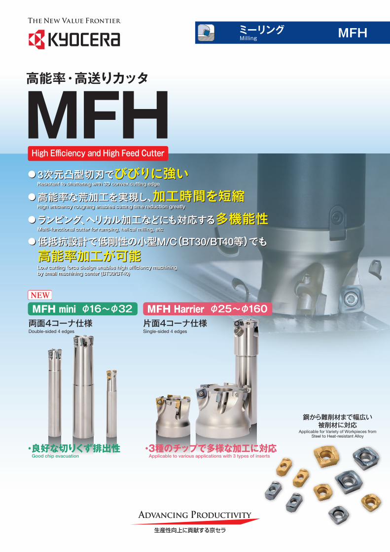
High Efficiency and High Feed Cutter
MFH高能率・高送りカッタ
●ランピング、ヘリカル加工などにも対応する多機能性Multi-functional cutter for ramping, helical milling, etc.
● 3次元凸型切刃でびびりに強いResistant to chattering with 3D convex cutting edge
●高能率な荒加工を実現し、加工時間を短縮High efficiency roughing enables cutting time reduction greatly
●低抵抗設計で低剛性の小型M/C(BT30/BT40等)でも 高能率加工が可能
Low catting force design enables high efficiency machining by small machining center (BT30/BT40)
Millingミーリング
鋼から難削材まで幅広い被削材に対応
Applicable for Variety of Workpieces from Steel to Heat-resistant Alloy
MFH
両面4コーナ仕様Double-sided 4 edges
MFH mini φ16~φ32NEW
・良好な切りくず排出性 Good chip evacuation
片面4コーナ仕様Single-sided 4 edges
MFH Harrier φ25~φ160
・3種のチップで多様な加工に対応 Applicable to various applications with 3 types of inserts
1
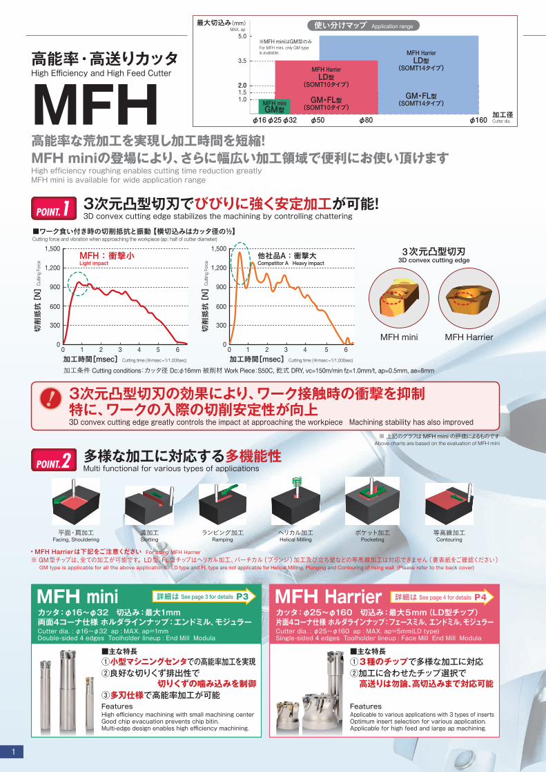
MFH高能率な荒加工を実現し加工時間を短縮!MFH miniの登場により、さらに幅広い加工領域で便利にお使い頂けますHigh efficiency roughing enables cutting time reduction greatlyMFH mini is available for wide application range
高能率・高送りカッタ High Efficiency and High Feed Cutter
最大切込み(mm)
φ25 φ50 φ80φ32 φ160φ16
MAX. ap
2.0
1.0
加工径Cutter dia.
※MFH miniはGM型のみFor MFH mini, only GM type is available.
使い分けマップ Application range
1.52.0
3.5
5.0
MFH HarrierLD型
(SOMT10タイプ)
MFH HarrierLD型
(SOMT14タイプ)
GM・FL型(SOMT10タイプ)
GM・FL型(SOMT14タイプ)MFH mini
GM型
FeaturesHigh efficiency machining with small machining centerGood chip evacuation prevents chip bitin.Multi-edge design enables high efficiency machining.
■主な特長①小型マシニングセンタでの高能率加工を実現②良好な切りくず排出性で
切りくずの噛み込みを制御③多刃仕様で高能率加工が可能
MFH miniカッタ:φ16~φ32 切込み:最大1mm 両面4コーナ仕様 ホルダラインナップ:エンドミル、モジュラーCutter dia. : φ16~φ32 ap : MAX. ap=1mm Double-sided 4 edges Toolholder lineup : End Mill Modula
詳細は See page 3 for details P3
FeaturesApplicable to various applications with 3 types of insertsOptimum insert selection for various application. Applicable for high feed and large ap machining.
■主な特長①3種のチップで多様な加工に対応②加工に合わせたチップ選択で 高送りは勿論、高切込みまで対応可能
MFH Harrierカッタ:φ25~φ160 切込み:最大5mm(LD型チップ) 片面4コーナ仕様 ホルダラインナップ:フェースミル、エンドミル、モジュラーCutter dia. : φ25~φ160 ap : MAX. ap=5mm(LD type) Single-sided 4 edges Toolholder lineup : Face Mill End Mill Modula
詳細は See page 4 for details P4
多様な加工に対応する多機能性Multi functional for various types of applications
・MFH Harrierは下記をご注意ください For using MFH Harrier ※ GM型チップは、全ての加工が可能です。LD型、FL型チップはヘリカル加工、バーチカル(プランジ)加工及び立ち壁などの等高線加工は対応できません(裏表紙をご確認ください) GM type is applicable for all the above applications. LD type and FL type are not applicable for Helical Milling, Plunging and Contouring of rising wall (Please refer to the back cover)
平面・肩加工Facing, Shouldering
ヘリカル加工Helical Milling
等高線加工Contouring
溝加工Slotting
ポケット加工Pocketing
ランピング加工Ramping
POINT.2
切削抵抗
[N]
■ワーク食い付き時の切削抵抗と振動 【横切込みはカッタ径の½】Cutting force and vibration when approaching the workpiece (ap: half of cutter diameter)
Cut
ting
Forc
e
加工時間[msec] Cutting time (※msec=1/1,000sec) 加工時間[msec] Cutting time (※msec=1/1,000sec)
0
600
1,200
1,500
900
300 切削抵抗
[N]
Cut
ting
Forc
e
0
600
1,200
1,500
900
300
0 01 2 3 4 5 6 1 2 3 4 5 6
他社品A : 衝撃大Competitor A Heavy impact
MFH : 衝撃小Light impact
加工条件 Cutting conditions:カッタ径 Dc:φ16mm 被削材 Work Piece:S50C, 乾式 DRY, vc=150m/min fz=1.0mm/t, ap=0.5mm, ae=8mm
3次元凸型切刃3D convex cutting edge
MFH mini MFH Harrier
3次元凸型切刃でびびりに強く安定加工が可能!3D convex cutting edge stabilizes the machining by controlling chatteringPOINT.1
※ 上記のグラフはMFH miniの評価によるものですAbove charts are based on the evaluation of MFH mini
3次元凸型切刃の効果により、ワーク接触時の衝撃を抑制特に、ワークの入際の切削安定性が向上3D convex cutting edge greatly controls the impact at approaching the workpiece Machining stability has also improved
!

2
MFH High Efficiency and High Feed Cutter
鋼から難削材まで幅広い被削材に対応する充実のチップレパートリー Applicable for Variety of Workpieces from Steel to Heat-resistant Alloy
耐摩耗性重視Long Tool Life Serious Consideration
薄膜CVDコーティング
CA6535 鋼加工用For Steel
MEGACOAT NANO
PR1525 鋳物加工用For Cast Iron
MEGACOAT NANO
PR1510
難削材加工第一推奨First recommendation for difficult-to-cut materials
MEGACOAT NANO
PR1535耐熱合金、チタン合金、析出硬化系ステンレス鋼用For Ni-base heat resistant alloy, titanium alloy and precipitation hardened stainless steel
加工実例 Case Studies
突発欠損を抑制し安定加工を実現する難削材用新材種登場!New grade for difficult-to-cut material which controls sudden fracture and realizes stable machining
母材粒子の最適化と均一化による安定性の向上 Stability improvement by optimization and homogenization of the particles of matrix.
・粒子の最適化により、強い衝撃、不安定加工に対応 The optimization of the particles, corresponding strong impact and processing Instability
・熱伝導率:※約11% 向上、湿式加工時のヒートクラックを抑制 Conductivity is at approximately 11% improvements in Heat cracks at wet machining is repressed
・組織を均一化する事で、組織内の破壊源を低減 In uniformalize tissue, fracture origins of interstitial is reduced.
※:当社従来比Our conventional material ratio
POINT.2 ダイヤモンド圧子によるクラック比較Cracks compare by diamond indentor
クラックが長いClacks is long
クラックが短く分散Clacks are doing short dispersion
→ 耐衝撃性向上 High-impact improvement
従来材種Conventional material
PR1535母材PR1535 base material
新開発高靭性母材Newly Developed Tougher Substrate
新コバルト配合比率による強靭化 Toughening by a new cobalt mixing ratio. POINT.1
破壊靭性値: 約23%向上※ Fracture toughness values are at approximately 23% improvements
50
20
析出硬化系ステンレス鋼Precipitation hardening stainless steels
・航空機部品 Aircraft parts ・Vc=120m/min ・fz=0.6mm/t・ap×ae=0.7 x~25mm ・乾式 Dry
・MFH25-S25-03-4T (4枚刃) 4 inserts ・LOGU030310ER-GM (PR1535)
PR1535 加工個数 100個Machining efficiency:100pcs
他社品 A (5枚刃)Competitor A (5 inserts)
加工個数 55個Machining efficiency:55 pcs
・PR1535は、100個加工後も刃先状態が良好で安定加工が可能・PR1535 kept good edge condition and stable machining after machining 100 pcs.
(ユーザー様の評価による) User Evaluation
寿命1.8倍以上More than Tool life 1.8times
MFH mini SUS304F
・クラッチ Clutch ・Vc=120m/min ・fz=1.2mm/t・ap×ae=1.0×20mm ・乾式 Dry
・MFH32-S32-10-2T(2枚刃) 2 inserts ・SOMT100420ER-GM (PR1535)
PR1535 切りくず排出量=58cc/分Chip evacuation
他社品 BCompetitor B
切りくず排出量=36cc/分Chip evacuation
ビビリ解消Chattering reduced
加工能率1.6倍Efficiency: 1.6 times
・他社品Bはビビリが発生していたが、MFH型は安定加工が可能・刃先状態が良好で、長寿命加工が可能・Competitor B caused chattering but MFH realized stable machining・Good edge condition and long tool life
(ユーザー様の評価による) User Evaluation
MFH Harrier
3
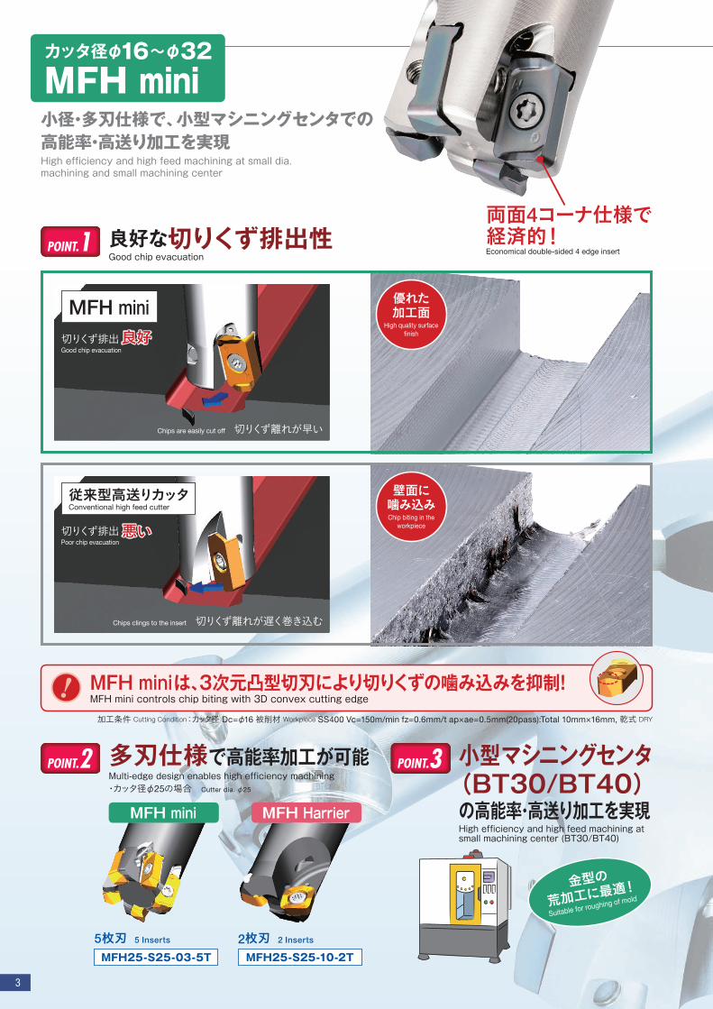
良好な切りくず排出性Good chip evacuation
POINT.1
カッタ径φ16~φ32
MFH mini小径・多刃仕様で、小型マシニングセンタでの高能率・高送り加工を実現High efficiency and high feed machining at small dia. machining and small machining center
両面4コーナ仕様で経済的!Economical double-sided 4 edge insert
POINT.2 多刃仕様で高能率加工が可能Multi-edge design enables high efficiency machining・カッタ径φ25の場合 Cutter dia. φ25
POINT.3 小型マシニングセンタ(BT30/BT40)
の高能率・高送り加工を実現High efficiency and high feed machining at small machining center (BT30/BT40)
MFH mini
Chips are easily cut off 切りくず離れが早い
切りくず排出 良好Good chip evacuation
優れた加工面
High quality surface finish
従来型高送りカッタConventional high feed cutter
Chips clings to the insert 切りくず離れが遅く巻き込む
切りくず排出 悪いPoor chip evacuation
壁面に噛み込みChip biting in the
workpiece
MFH mini
MFH25-S25-03-5T
5枚刃 5 Inserts
MFH Harrier
MFH25-S25-10-2T2枚刃 2 Inserts
金型の荒加工に最
適!Suitable for roughing of mold
加工条件 Cutting Condition:カッタ径 Dc=φ16 被削材 Workpiece SS400 Vc=150m/min fz=0.6mm/t ap×ae=0.5mm(20pass):Total 10mm×16mm, 乾式 DRY
MFH miniは、3次元凸型切刃により切りくずの噛み込みを抑制!MFH mini controls chip biting with 3D convex cutting edge
!

4
3種のチップで多様な加工に対応Various applications with 3 types of inserts
POINT.1GM型(汎用)GM (General purpose)
汎用加工の第一推奨面加工からランピング、ヘリカルなど
多様な加工に対応First recommendation for general machining
For various application from facing, ramping to helical milling
LD型(高切込み対応)LD (Large ap)
最大 ap=5mm まで対応黒皮からの加工が可能で高送りもこなす1台2役
MAX. ap=5mmApplicable to scaling as well
as high feed cutting
FL型(低抵抗)FL (Low cutting force)
低抵抗設計でさらい刃付きびびり低減と優れた仕上げ面の
両立を実現Wiper insert with low cutting force
Excellent surface finish and chattering reduction
カッタ径φ25~φ160
MFH Harrier3種のチップで幅広い加工に対応加工時間短縮を実現Applicable to various applications with 3 types of insertsSignificant cutting time reduction
加工に合わせたチップ選択で多様な加工に対応可能!Optimum insert selection for various application. Applicable for high feed and large ap machining.
黒皮部は高切込み、その後の荒加工は高送りで高能率
加工を実現しますMachining efficiency can be improved by large ap machining
for removing scale and high-feed machining for roughing
I want a cutter which can be used both at large ap and high feed rate
LD type is available for large ap (Max.5mm) as well as high feed rate at low ap machining
For both large ap and high feed rate Tips for using LD type insert
高切込みも、高送りもしたい LD型チップ の上手な使い方※10タイプは3.5mm
3.5mm for 10-type insert
MFH型は汎用カッタに比べ2.6倍の加工能率 !!MFH improved machining efficiency by 2.6 times compared with the conventional cutter
黒皮部は高切込みで加工Large ap for scale removal
(fz=0.25mm/t ap=4mm) ガッツリ削れる!High chipremoval volume
その後の加工は高送りHigh feed rate after scaling
(fz=1.5mm/t ap=2mm)
高送り加工!High feed machining
MFH型
● 荒加工(2パス)黒皮部は高切込みで加工 Roughing for scale removal (2 passes): Large ap
Vc=200m/min fz=0.25mm/t ap×ae=4×40mm Vf=1,264mm/min
● その後の荒加工(2パス)は高送りで加工 Roughing (2 passes)after scaling: High feed rate
Vc=200m/min fz=1.5mm/t ap×ae=2×40mm Vf=7,583mm/min 被削材:SS400 Workpiece
切りくず排出量=404cc/minChip evacuation
※MFH063R-14-5T-22M(カッタ径 Cutter dia.φ63 5枚刃 63mm, 5 inserts)
汎用45°カッタConventional 45°cutter
● 荒加工(4パス)は一定の取り代、送りで加工 Roughing (4 passes): Constant ap and feed rate
Vc=200m/min fz=0.25mm/t ap×ae=3×40mm Vf=1,264mm/min 被削材:SS400 Workpiece
切りくず排出量=151cc/minChip evacuation
※カッタ径 Cutter dia.φ63 5枚刃 63mm, 5 inserts

5
MFH mini エンドミル MFH mini End Mill
最高回転数の表記についてCaution with Max. Revolution
誤って最高回転数以上に回転させた場合、遠心力によりチップや部品の飛散等が生じる場合がありますのでご注意願います。When running an endmill or a cutter at the maximum revolution, the insert or cutter may be damaged or scatter by centrifugal force.
焼付き防止剤(MP-1)は、チップを固定する際、クランプスクリューのテーパ部とねじ部に薄く塗布してご使用ください。Apply Anti-seize Compound (MP-1) thinly on portion of taper and thread when insert is fixed.
●
●
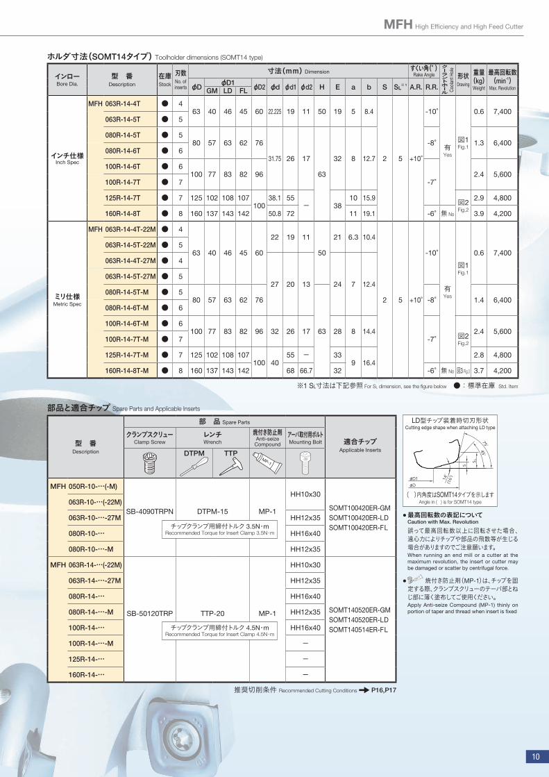
部品と適合チップ Spare Parts and Applicable Inserts
推奨切削条件 Recommended Cutting Conditions P7
型 番Description
部 品 Spare Parts
適合チップApplicable Inserts
クランプスクリューClamp Screw
レンチWrench
焼付き防止剤Anti-seize Compound
MFH …-03-…SB-3065TRP DTPM-8 MP-1
LOGU030310ER-GMチップクランプ用締付トルク 1.2N・mRecommended Torque for Insert Clamp 1.2N・m
ホルダ寸法 Toolholder dimensions
●:標準在庫 Std. Item
シャンクShank
型 番Description
在庫Stock
刃数No. of inserts
寸法(mm) Dimension すくい角(° )Rake Angle
クーラントホール
形状Drawing
重量(kg)
Weight
最高回転数(min-1)
Max. RevolutionφD φD1 φd L ℓ S A.R. R.R.
標準シャンクStandard (Straight)
MFH 16-S16-03-2T ● 2 16 8 16 100 30
1 -10° -15° 有Yes
図1Fig.1
0.1 18,800 20-S20-03-3T ● 3
20 12 20 130 50 0.3 15,700 20-S20-03-4T ●
425-S25-03-4T ●
25 17 25 140 60 0.5 13,400 25-S25-03-5T ●
532-S32-03-5T ●
32 24 32 150 70 0.8 11,400 32-S32-03-6T ● 6
オーバーサイズシャンクOver Size(Straight)
MFH 17-S16-03-2T ●2
17 916 100 20
図2Fig.2
0.117,900
18-S16-03-2T ● 18 10 17,000 22-S20-03-3T ● 3
22 14 20 130 30 0.3 14,700 22-S20-03-4T ●
428-S25-03-4T ●
28 20 25 140 40 0.5 12,400 28-S25-03-5T ● 5
ウェルドンシャンクStandard(Weldon)
MFH 16-W16-03-2T ● 2 16 8 16 79 30
図3Fig.3
0.1 18,800 20-W20-03-3T ● 3
20 12 20 101 50 0.2 15,700 20-W20-03-4T ●
425-W25-03-4T ●
25 17 25 117 60 0.4 13,400 25-W25-03-5T ●
532-W32-03-5T ●
32 24 32 131 70 0.7 11,400 32-W32-03-6T ● 6
ロングシャンクLong Shank
(Straight)
MFH 16-S16-03-2T-150 ● 2 16 8 16 150 50
図1Fig.1
0.2 18,800 20-S20-03-3T-160 ● 3 20 12 20 160 80 0.3 15,700 25-S25-03-4T-180 ● 4 25 17 25 180 100 0.6 13,400 32-S32-03-5T-200 ● 5 32 24 32 200 120 1.1 11,400
Coo
lant
Hol
e
図1Fig.1
図2Fig.2
図3Fig.3
S
S
ℓL
φdh6
φdh6
φdh6
φD1
φD1
φD
φD
ℓL
(ストレートシャンク)Standard (Straight)
カッタ径φ16~φ32MFH mini

6
MFH High Efficiency and High Feed Cutter
●:標準在庫 Std. Item
ホルダ寸法 Toolholder dimensions
型 番Description
在庫Stock
刃数No. of inserts
寸法(mm) Dimension すくい角(° )Rake Angle
クーラントホール
最高回転数(min-1)
Max. RevolutionφD φD1 φD2 φd L ℓ M1 H B S A.R. R.R.
MFH 16-M08-03-2T ●2
16 814.7 8.5 43 25 M8xP1.25 12 8
1 -10° -15° 有Yes
18,88017-M08-03-2T ● 17 9 17,90018-M08-03-2T ● 18 10 17,00020-M10-03-3T ● 3
20 1218.7 10.5 49 30 M10xP1.5 15 9
15,70020-M10-03-4T ● 422-M10-03-3T ● 3
22 14 14,70022-M10-03-4T ●
425-M12-03-4T ●
25 17 2312.5 57 35 M12xP1.75 19 10
13,40025-M12-03-5T ● 528-M12-03-4T ● 4
28 20 23 12,40028-M12-03-5T ●
532-M16-03-5T ●
32 24 30 17 63 40 M16xP2 24 12 11,40032-M16-03-6T ● 6
Coo
lant
Hol
e
● : 標準在庫 Std. Item
適合チップ Applicable Inserts
形 状Insert
型 番Description
寸法(mm)Dimension
角度(° )Angle
MEGACOAT NANOCVD
コーティングCVD Coated Carbide
A T φd W Z rε α PR1535 PR1525 PR1510 CA6535
汎用General Purpose
T
W
A
rε
φd
LOGU 030310ER-GM 6.2 3.96 3.45 11.9 - 1.0 - ● ● ● ●
MFH mini ヘッド MFH mini Head
S
ℓ
L
B
M1
A
A H
φD1
φd
φD2
φD
A-A断面A-A Section
L1 L2
φD
M
アーバ型番Arbor Description
適合エンドミルApplicable End Mill
エンドミル有効深さ (mm)Actual End Mill depth
型 番Description
加工径Cutting Dia.
寸法Dimension
M L2φD L1
BT30K- M08-45MFH16-M08-03… φ16
2531.8 6.8
MFH17-M08-03… φ17 33.2 8.2MFH18-M08-03… φ18 34.2 9.2
M10-45 MFH20-M10-03… φ20
3036.8 6.8
MFH22-M10-03… φ22 39.2 9.2
M12-45MFH25-M12-03… φ25
3542.8 7.8
MFH28-M12-03… φ28 45.5 10.5
BT40K- M08-55 MFH16-M08-03… φ16
2531.7 6.7
MFH17-M08-03… φ17 33.2 8.2MFH18-M08-03… φ18 34.3 9.3
M10-60 MFH20-M10-03… φ20
3038.7 8.7
MFH22-M10-03… φ22 44.5 14.5
M12-55 MFH25-M12-03… φ25
3544.6 9.6
MFH28-M12-03… φ28 47.6 12.6M16-65 MFH32-M16-03… φ32 40 51.2 11.2
エンドミル有効深さ Actual end mill depth
BTアーバーはP14をご確認ください For BT type arbor, see page 14.

7
切削能力(GM型) Cutting Performance (GM)
注) 多刃仕様は標準刃仕様に比べ推奨条件を下げる必要があります。 When using close pitch type, reduce the cutting conditions compared with standard type
0.5 1.0 1.5
0.5
1.0
送り Feed Rate fz(mm/t)
切込み深さ
ap(
mm
)C
uttin
g D
epth
多刃仕様Close pitch
0.3
0.8
0.5 1.0 1.5
0.5
1.0
送り Feed Rate fz(mm/t)
切込み深さ
ap(
mm
)C
uttin
g D
epth
標準刃仕様 (カッタ径φ16~φ22)Standard pitch
0.6
1.2
0.5 1.0 1.5
0.5
1.0
送り Feed Rate fz(mm/t)
切込み深さ
ap(
mm
)C
uttin
g D
epth
標準刃仕様 (カッタ径φ25~φ32)Standard pitch
0.8
形状Shape
型 番Holder
チップ形状Insert
切込み角 γ(° )Cutting edge angle
近似 R(mm)Approx. R
削り残し量 K(mm)
Unmachined part
等高線加工時のワーク最大傾斜角(° )
Max. inclination angle of workpiece at contouring
MFH…-03-… GM 12° 1.6 0.39 90°
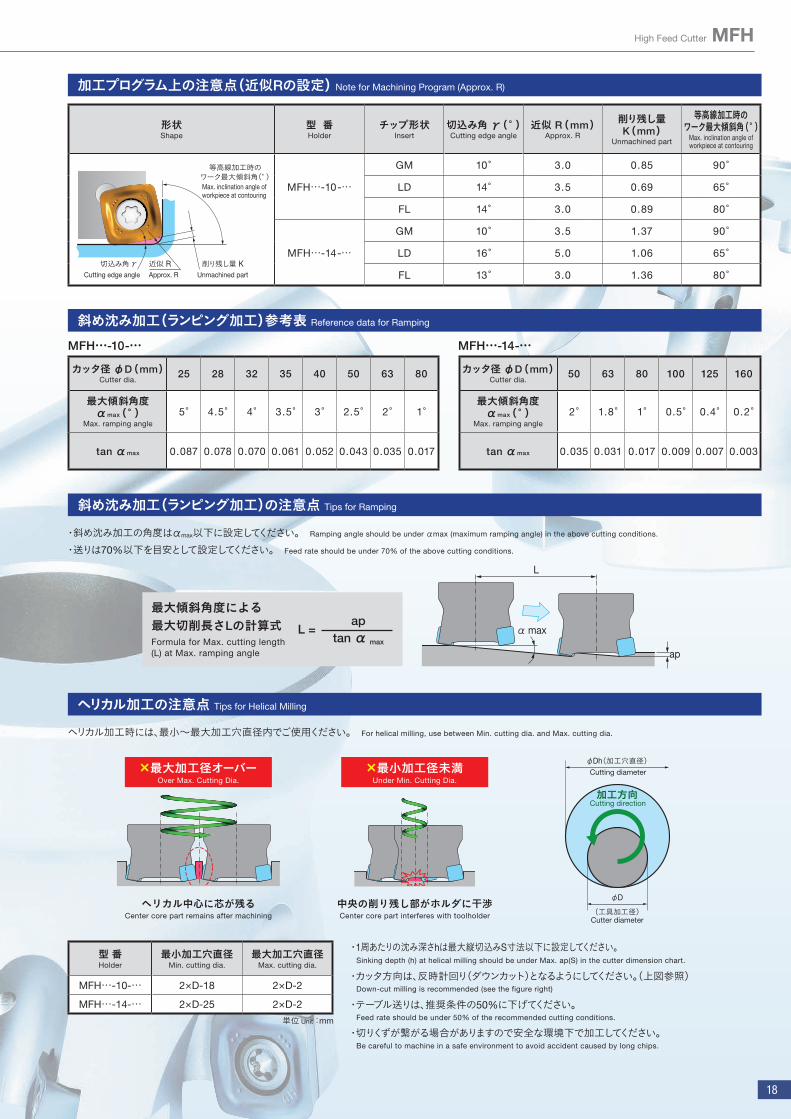
加工プログラム上の注意点(近似Rの設定) Note for Machining Program (Approx. R)
削り残し量 KUnmachined partApprox. R
近似 R
切込み角 γ(° )Cutting edge angle切込み角 γ(° )Cutting edge angle
Max. inclination angle of workpiece at contouringMax. inclination angle of workpiece at contouring
等高線加工時のワーク最大傾斜角(° )等高線加工時のワーク最大傾斜角(° )
MFH20-…-4T, MFH22-…-4T, MFH25-…-5TMFH28-…-5T, MF32-…-6T
MFH16-…-2T, MFH17-…-2T, MFH18-…-2T MFH20-…-3T, MFH22-…-3T
MFH25-…-4T, MFH28-…-4T, MFH32-…-5T
カッタ径φ16~φ32MFH mini
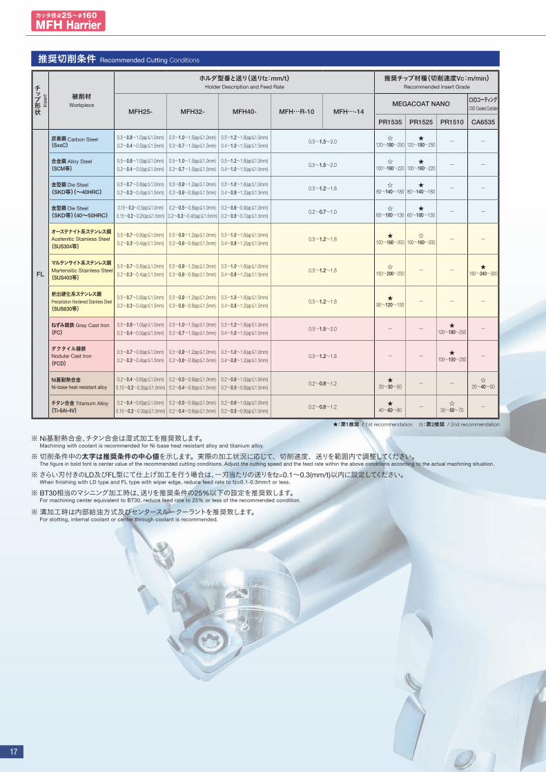
※ Ni基耐熱合金、チタン合金は湿式加工を推奨致します。 切削条件中の太字は推奨条件の中心値を示します。実際の加工状況に応じて、切削速度、送りを範囲内で調整してください。BT30相当のマシニング加 工時は、送りを推奨条件の 25%以下の設定を推奨致します。溝加工時は内部給油方式及びセンタースルークーラントを推奨致します。 Machining with coolant is recommended for Ni-base heat resistant alloy and titanium alloy. The figure in bold font is center value of the recommended cutting conditions. Adjust the cutting speed and the feed rate within the above conditions according to the actual machining situation. For machining center equivalent to BT30, reduce feed rate to 25% or less of the recommended condition. For slotting, internal coolant or center through coolant is recommended.
推奨切削条件 Recommended Cutting Conditions
■標準刃仕様 / Standard pitch ■多刃仕様 / Close pitch ★:第1推奨 / 1st recommendation ☆:第2推奨 / 2nd recommendation
チップ形状
被削材Workpiece
ホルダ型番と送り(送りfz:mm/t)Holder Description and Feed Rate
推奨チップ材種(切削速度Vc:m/min) Recommended Insert Grade
MFH16-…-2T
MFH20-…-3T
MFH20-…-4T
MFH25-…-4T
MFH25-…-5T
MFH32-…-5T
MFH32-…-6T
MEGACOAT NANO CVDコーティングCVD Coated Carbide
PR1535 PR1525 PR1510 CA6535
GM
炭素鋼 Carbon Steel (SxxC)
0.2~0.7~1.2 0.2~0.5~0.8 0.2~0.8~1.5 0.2~0.5~0.8 0.2~0.8~1.5 0.2~0.5~0.8
☆ 120~180~250
★ 120~180~250 - -
合金鋼 Alloy Steel (SCM等)
☆ 100~160~220
★ 100~160~220 - -
金型鋼 Die Steel(SKD等)(~40HRC)
0.2~0.5~0.9 0.2~0.4~0.6 0.2~0.6~1.2 0.2~0.4~0.6 0.2~0.6~1.2 0.2~0.4~0.6 ☆ 80~140~180
★ 80~140~180 - -
金型鋼 Die Steel(SKD等)(40~50HRC)
0.2~0.3~0.5 0.2~0.25~0.3 0.2~0.3~0.6 0.2~0.25~0.3 0.2~0.3~0.6 0.2~0.25~0.3 ☆ 60~100~130
★ 60~100~130 - -
オーステナイト系ステンレス鋼Austenitic Stainless Steel
(SUS304等)
0.2~0.5~0.9 0.2~0.4~0.6 0.2~0.6~1.2 0.2~0.4~0.6 0.2~0.6~1.2 0.2~0.4~0.6
★ 100~160~200
☆ 100~160~200 - -
マルテンサイト系ステンレス鋼Martensitic Stainless Steel (SUS403等)
☆ 150~200~250 - - ★
180~240~300
析出硬化系ステンレス鋼Precipitation Hardened Stainless Steel(SUS630等)
★ 90~120~150 - - -
ねずみ鋳鉄 Gray Cast Iron(FC)
0.2~0.7~1.2 0.2~0.5~0.8 0.2~0.8~1.5 0.2~0.5~0.8 0.2~0.8~1.5 0.2~0.5~0.8 - - ★ 120~180~250 -
ダクタイル鋳鉄 Nodular Cast Iron
(FCD)0.2~0.5~0.9 0.2~0.4~0.6 0.2~0.6~1.2 0.2~0.4~0.6 0.2~0.6~1.2 0.2~0.4~0.6 - - ★
100~150~200 -
Ni基耐熱合金Ni-base heat resistant alloy
0.2~0.3~0.6 0.2~0.25~0.4 0.2~0.4~0.8 0.2~0.25~0.4 0.2~0.4~0.8 0.2~0.25~0.4
☆ 20~30~50 - - ★
20~30~50
チタン合金 Titanium Alloy (Ti-6Al-4V)
★ 40~60~80 - ☆
30~50~70 -
Inse
rt
※ ap=0.5mmの推奨送り(基準値)Recommended Feed ap=0.5mm(reference value)

8
MFH High Efficiency and High Feed Cutter
ヘリカル加工の注意点 Tips for Helical Milling
・ヘリカル加工時には、最小~最大加工穴直径内でご使用ください。 For helical milling, use between Min. cutting dia. and Max. cutting dia.
×最大加工径オーバーOver Max. Cutting Dia.
ヘリカル中心に芯が残るCenter core part remains after
machining
×最小加工径未満Under Min. Cutting Dia.
中央の削り残し部がホルダに干渉
Center core part interferes with toolholder
φDh(加工穴直径)
加工方向
φD
(工具加工径)
Cutting diameter
Cutter diameter
Cutting direction
・1周あたりの沈み深さは最大縦切込みap(1mm)以内にしてください。Sinking depth per rotation should be smaller than Max. ap (1mm).
・カッタ方向は、反時計回り(ダウンカット)となるようにしてください。(上図参照)Down-cut milling is recommended (see the figure right)
・テーブル送りは、推奨条件の50%に下げてください。Feed rate should be under 50% of the recommended cutting conditions.
・切りくずが繋がる場合がありますので安全な環境下で加工してください。Be careful to machine in a safe environment to avoid accident caused by long chips.
型 番Holder
最小加工穴直径 φDh1Min. cutting dia.
最大加工穴直径 φDh2Max. cutting dia.
MFH…-03-… 2×D-8 2×D-2
単位 Unit :mm
斜め沈み加工(ランピング加工)の注意点 Tips for Ramping
・斜め沈み加工の角度はαmax以下に設定してください。Ramping angle should be under αmax (maximum ramping angle) in the above cutting conditions.
・送りは70%以下を目安として設定してください。Feed rate should be under 70% of the above cutting conditions.
最大傾斜角度による最大切削長さLの計算式Formula for Max. cutting length (L) at Max. ramping angle
L = ap
tan α max
ap
α max
L
斜め沈み加工(ランピング加工)参考表 Reference data for Ramping
型 番Description
カッタ径 φD(mm)Cutter dia.
16 17 18 20 22 25 28 32
MFH …-03-…最大傾斜角度 αmax(° )
Max. ramping angle2.8° 2.5° 2.1° 1.7 ° 1.4° 1.2° 1° 0.8°
tan αmax 0.049 0.042 0.037 0.03 0.024 0.021 0.017 0.014
バーチカル(プランジ)について Vertical milling (Plunging)
バーチカル(プランジ)加工 Vertical milling (Plunging)
・バーチカル(プランジ)加工が可能です Available for vertical milling
チップ型番Maximum
最大横切込み(ae)Maximum Width of Cut (ae)
LOGU03型 3.5mm
・ バーチカル加工時の送りはfz=0.2(mm/t)以内に設定してください。For vertical milling (plunging), reduce feed rate to fz=0.2mm/t or less.
ドリリング加工の注意点 Tips for Drilling
φD
Pd
中心部コアCenter core
X 型 番Holder
GM型
最大加工深さ Pd
Max. cutting depth
底面が平坦となる最小切削長 X
Min. cutting length X for flat bottom surface
MFH…-03-… 1.0 φD-9
単位 Unit :mm
※ ドリリング後、そのまま横送り加工を行う場合は、削り残し部分が切削されるまでは内刃 (切込み角度80°部分)も切削に使用するため、テーブル送りを推奨条件の25%以下にして下さい。※ ドリリング加工時は、軸方向送り速度を0.2mm/rev以下にしてください。 When traversing directly after drilling, set the table feed at up to 25% of the recommended cutting conditions. when drilling, reduce feed rateper revolution to under f=0.2mm/rev.

9
MFH Harrier フェースミル MFH Harrier Face Mill
SH
bφdφD2
a
φ18
φ26
E
φd1φd2
φDφD1
bφdφD2
aE
φd1φD1φD
SH
bφdφD2
aE
HS
φd2φd1φD1φD
図1 図3図2Fig.3Fig.2Fig.1
SH
bφdφD2
a
φ18
φ26
E
φd1φd2
φDφD1
bφdφD2
aE
φd1φD1φD
SH
bφdφD2
aE
HS
φd2φd1φD1φD
図1 図3図2Fig.3Fig.2Fig.1
ホルダ寸法(SOMT10タイプ) Toolholder dimensions (SOMT10 type)
インローBore Dia.
型 番Description
在庫Stock
刃数No. of inserts
寸法(mm) Dimension すくい角(° )Rake Angle
クーラントホール
形状Drawing
重量(kg)
Weight
最高回転数(min-1)
Max. RevolutionφDφD1 φD2 φd φd1 φd2 H E a b S SL
※ 1 A.R. R.R.GM LD FL
インチ仕様Inch Spec
MFH 050R-10-4T ● 450 33 37.5 36.5 47
22.225 19 11 50 19 5 8.4
1.5(1.2)※ 2
3.5
+10°
-5°
有Yes図1 Fig.1
0.4 10,000050R-10-5T ● 5
063R-10-5T ● 563 46 50.5 49.5 60
-4°0.7 8,800
063R-10-6T ● 6
080R-10-7T ● 7 80 63 67.5 66.5 76 31.75 26 17 63 32 8 12.7 1.3 7,600
ミリ仕様Metric Spec
MFH 050R-10-4T-M ● 450 33 37.5 36.5 47
22 19 11
50
21 6.3 10.4
+10°
-5°
有Yes図1 Fig.1
0.4 10,000 050R-10-5T-M ● 5
063R-10-5T-22M ● 5
63 46 50.5 49.5 60-4°
0.7 8,800 063R-10-6T-22M ● 6
063R-10-5T-27M ● 5
27 20 13 24 7 12.4063R-10-6T-27M ● 6
080R-10-7T-M ● 7 80 63 67.5 66.5 76 63 1.6 7,600
※1 SL寸法はP10下記参照 For SL dimension, see P10 figure below ※2 ( )内寸法はLD型チップ装着時を示します Dimension in ( ) is when attaching LD type ● : 標準在庫 Std. Item
Cool
ant H
ole
カッタ径φ25~φ160
MFH Harrier
10
MFH High Efficiency and High Feed Cutter
部品と適合チップ Spare Parts and Applicable Inserts
型 番Description
部 品 Spare Parts
適合チップApplicable Inserts
クランプスクリューClamp Screw
レンチWrench
焼付き防止剤Anti-seize
Compound
アーバ取付用ボルトMounting Bolt
DTPM TTP
MFH 050R-10-…(-M)
SB-4090TRPN DTPM-15 MP-1
HH10x30
SOMT100420ER-GMSOMT100420ER-LDSOMT100420ER-FL
063R-10-…(-22M)
063R-10-…-27M HH12x35
080R-10-… HH16x40
080R-10-…-M HH12x35
MFH 063R-14-…(-22M)
SB-50120TRP TTP-20 MP-1
HH10x30
SOMT140520ER-GMSOMT140520ER-LDSOMT140514ER-FL
063R-14-…-27M HH12x35
080R-14-… HH16x40
080R-14-…-M HH12x35
100R-14-… HH16x40
100R-14-…-M -
125R-14-… -
160R-14-… -
ホルダ寸法(SOMT14タイプ) Toolholder dimensions (SOMT14 type)
インローBore Dia.
型 番Description
在庫Stock
刃数No. of inserts
寸法(mm) Dimension すくい角(° )Rake Angle
クーラントホール
形状Drawing
重量(kg)
Weight
最高回転数(min-1)
Max. RevolutionφDφD1 φD2 φd φd1 φd2 H E a b S SL
※ 1 A.R. R.R.GM LD FL
インチ仕様Inch Spec
MFH 063R-14-4T ● 463 40 46 45 60 22.225 19 11 50 19 5 8.4
2 5 +10°
-10°
有Yes
図1Fig.1
0.6 7,400063R-14-5T ● 5
080R-14-5T ● 580 57 63 62 76
31.75 26 17
63
32 8 12.7
-8° 1.3 6,400080R-14-6T ● 6
100R-14-6T ● 6100 77 83 82 96
-7°2.4 5,600
100R-14-7T ● 7
125R-14-7T ● 7 125 102 108 107100
38.1 55- 38
10 15.9 図2Fig.2
2.9 4,800
160R-14-8T ● 8 160 137 143 142 50.8 72 11 19.1 -6° 無 No 3.9 4,200
ミリ仕様Metric Spec
MFH 063R-14-4T-22M ● 4
63 40 46 45 60
22 19 11
50
21 6.3 10.4
2 5 +10°
-10°
有Yes
図1Fig.1
0.6 7,400063R-14-5T-22M ● 5
063R-14-4T-27M ● 4
27 20 13 24 7 12.4063R-14-5T-27M ● 5
080R-14-5T-M ● 580 57 63 62 76
63
-8° 1.4 6,400 080R-14-6T-M ● 6
100R-14-6T-M ● 6100 77 83 82 96 32 26 17 28 8 14.4
-7° 図2Fig.2
2.4 5,600 100R-14-7T-M ● 7
125R-14-7T-M ● 7 125 102 108 107100 40
55 - 339 16.4
2.8 4,800
160R-14-8T-M ● 8 160 137 143 142 68 66.7 32 -6° 無 No 図3 Fig.3 3.7 4,200
※1 SL寸法は下記参照 For SL dimension, see the figure below ● : 標準在庫 Std. Item
S
S L
14°
(16°)
45°75°
φD1φD
LD型チップ装着時切刃形状
Angle in ( ) is for SOMT14 type
Cutting edge shape when attaching LD type
( )内角度はSOMT14タイプを示します
最高回転数の表記についてCaution with Max. Revolution
誤って最高回転数以上に回転させた場合、遠心力によりチップや部品の飛散等が生じる場合がありますのでご注意願います。When running an end mill or a cutter at the maximum revolution, the insert or cutter may be damaged or scatter by centrifugal force.
焼付き防止剤(MP-1)は、チップを固定する際、クランプスクリューのテーパ部とねじ部に薄く塗布してご使用ください。Apply Anti-seize Compound (MP-1) thinly on portion of taper and thread when insert is fixed
●
●
チップクランプ用締付トルク 3.5N・mRecommended Torque for Insert Clamp 3.5N・m
チップクランプ用締付トルク 4.5N・mRecommended Torque for Insert Clamp 4.5N・m
Cool
ant H
ole
推奨切削条件 Recommended Cutting Conditions P16,P17
11
MFH Harrier エンドミル(SOMT10タイプ) MFH Harrier End Mill (SOMT10 type)
部品と適合チップ Spare Parts and Applicable Inserts
図1Fig.1
図2Fig.2
図3Fig.3
図4Fig.4
S
S
ℓ
ℓ
L
L
φdh6
φdh6
φdh6
φdh6
φD1
φD1
φD
φD(ストレートシャンク)Standard (Straight)
最高回転数の表記についてCaution with Max. Revolution
誤って最高回転数以上に回転させた場合、遠心力によりチップや部品の飛散等が生じる場合がありますのでご注意願います。When running an endmill or a cutter at the maximum revolution, the insert or cutter may be damaged or scatter by centrifugal force.
焼付き防止剤(MP-1)は、チップを固定する際、クランプスクリューのテーパ部とねじ部に薄く塗布してご使用ください。Apply Anti-seize Compound (MP-1) thinly on portion of taper and thread when insert is fixed.
●
●
型 番Description
部 品 Spare Parts
適合チップApplicable Inserts
クランプスクリューClamp Screw
レンチWrench
焼付き防止剤Anti-seize Compound
MFH …-10-…SB-4075TRP DTPM-15 MP-1 SOMT100420ER-GM
SOMT100420ER-LDSOMT100420ER-FL
チップクランプ用締付トルク 3.5N・mRecommended Torque for Insert Clamp 3.5N・m
推奨切削条件 Recommended Cutting Conditions P16,P17
ホルダ寸法(SOMT10タイプ) Toolholder dimensions (SOMT10 type)
型 番Description
在庫Stock
刃数No. of inserts
寸法(mm) Dimension すくい角(° )Rake Angle
クーラントホール
形状Drawing
重量(kg)
Weight
最高回転数(min-1)
Max. RevolutionφDφD1 φd L ℓ S SL A.R. R.R.GM LD FL
ストレートシャンクStandard (Straight)
MFH 25-S25-10-2T ● 2 25 8 12.5 11.525 140
60
1.5(1.2)
※3.5 +10° -5° 有
Yes
図3 Fig.3 0.4 17,000 28-S25-10-2T ● 2 28 11 15.5 14.5 40 図1 Fig.1 0.5 15,500 32-S32-10-2T ● 2
32 15 19.5 18.5
32 150
70 図3Fig.3
0.814,000
32-S32-10-3T ● 335-S32-10-2T ● 2
35 18 22.5 21.550 図1
Fig.1
13,000 35-S32-10-3T ● 340-S32-10-3T ● 3
40 23 27.5 26.5 0.9 11,500 40-S32-10-4T ● 4
ウェルドンシャンクStandard(Weldon)
MFH 25-W25-10-2T ● 2 25 8 12.5 11.5 25 117 601.5(1.2)
※3.5 +10° -5° 有
Yes
図4Fig.4
0.4 17,000 32-W32-10-3T ● 3 32 15 19.5 18.5
32131 70
0.714,000
40-W32-10-3T ● 340 23 27.5 26.5 112 50 図2
Fig.211,500
40-W32-10-4T ● 4
ロングシャンクLong Shank
(Straight)
MFH 25-S25-10-2T-200 ● 2 25 8 12.5 11.525
200
120
1.5(1.2)
※3.5 +10° -5° 有
Yes
図3 Fig.3 0.6 17,000 28-S25-10-2T-200 ● 2 28 11 15.5 14.5 40 図1 Fig.1 0.7 15,500 32-S32-10-2T-200 ● 2 32 15 19.5 18.5
32120 図3 Fig.3 1.0 14,000
35-S32-10-2T-200 ● 2 35 18 22.5 21.550 図1
Fig.1
1.4 13,000 40-S32-10-4T-250 ● 4 40 23 27.5 26.5 250 1.5 11,500
エキストラロングシャンク
Extra Long Shank(Straight)
MFH 25-S25-10-2T-300 ● 2 25 8 12.5 11.525
300
180
1.5(1.2)
※3.5 +10° -5° 有
Yes
図3 Fig.3 1.0 17,00028-S25-10-2T-300 ● 2 28 11 15.5 14.5 40 図1 Fig.1 1.1 15,50032-S32-10-2T-300 ● 2 32 15 19.5 18.5
32180 図3 Fig.3 1.6 14,000
35-S32-10-2T-300 ● 2 35 18 22.5 21.550 図1
Fig.1
1.7 13,00040-S32-10-4T-300 ● 4 40 23 27.5 26.5 1.8 11,500
※ ( )内寸法はLD型チップ装着時を示します Dimension in ( ) is when attaching LD type ●:標準在庫 Std. Item
Cool
ant H
ole
S
S L
14°
45°75°
φD1φD
LD型チップ装着時切刃形状Cutting edge shape when attaching LD type
カッタ径φ25~φ160
MFH Harrier

12
MFH High Efficiency and High Feed Cutter
MFH Harrier エンドミル(SOMT14タイプ) MFH Harrier End Mill (SOMT14 type)
部品と適合チップ Spare Parts and Applicable Inserts
型 番Description
部 品 Spare Parts
適合チップApplicable Inserts
クランプスクリューClamp Screw
レンチWrench
焼付き防止剤Anti-seize Compound
MFH …-14-…SB-50120TRP TTP-20 MP-1 SOMT140520ER-GM
SOMT140520ER-LDSOMT140514ER-FL
チップクランプ用締付トルク 4.5N・mRecommended Torque for Insert Clamp 4.5N・m
最高回転数の表記についてCaution with Max. Revolution
誤って最高回転数以上に回転させた場合、遠心力によりチップや部品の飛散等が生じる場合がありますのでご注意願います。When running an endmill or a cutter at the maximum revolution, the insert or cutter may be damaged by centrifugal force.
焼付き防止剤(MP-1)は、チップを固定する際、クランプスクリューのテーパ部とねじ部に薄く塗布してご使用ください。Coat Anti-seize Compound (MP-1) thinly on portion of taper and thread when insert is fixed.
●
●
ホルダ寸法(SOMT14タイプ) Toolholder dimensions (SOMT14 type)
●:標準在庫 Std. Item
型 番Description
在庫Stock
刃数No. of inserts
寸法(mm) Dimension すくい角(° )Rake Angle
クーラント
ホール
形状Drawing
重量(kg)
Weight
最高回転数(min-1)
Max. RevolutionφDφD1 φd L ℓ S SL A.R. R.R.GM LD FL
MFH 50-S42-14-3T ● 3 50 27 33 32
42 150 50 2 5 +10°-10° 有
Yes
図 1 Fig.1 1.4 8,800
63-S42-14-4T ● 4 63 40 46 45図 2 Fig.2
1.7 7,400
80-S42-14-5T ● 5 80 57 63 62 -8° 2.3 6,400
Coo
lant
Hol
e
φdh6
Sℓ
L
φD1
φD
φdh6
Sℓ
L
φD
φD1
図1Fig.1
図2Fig.2
S
S L
16°
45°75°
φD1φD
LD型チップ装着時切刃形状Cutting edge shape when attaching LD type
推奨切削条件 Recommended Cutting Conditions P16,P17
13
MFH Harrier ヘッド MFH Harrier Head
部品と適合チップ Spare Parts and Applicable Inserts
型 番Description
部 品 Spare Parts
適合チップApplicable Inserts
クランプスクリューClamp Screw
レンチWrench
焼付き防止剤Anti-seize Compound
MFH …-10-…SB-4075TRP DTPM-15 MP-1 SOMT100420ER-GM
SOMT100420ER-LDSOMT100420ER-FL
チップクランプ用締付トルク 3.5N・mRecommended Torque for Insert Clamp 3.5N・m
最高回転数の表記についてCaution with Max. Revolution
誤って最高回転数以上に回転させた場合、遠心力によりチップや部品の飛散等が生じる場合がありますのでご注意願います。When running an endmill or a cutter at the maximum revolution, the insert or cutter may be damaged by centrifugal force.
焼付き防止剤(MP-1)は、チップを固定する際、クランプスクリューのテーパ部とねじ部に薄く塗布してご使用ください。Coat Anti-seize Compound (MP-1) thinly on portion of taper and thread when insert is fixed.
●
●
ホルダ寸法 Toolholder dimensions
※ ( )内寸法はLD型チップ装着時を示します Dimension in ( ) is when attaching LD type ●:標準在庫 Std. Item
型 番Description
在庫Stock
刃数No. of inserts
寸法(mm) Dimension すくい角(° )Rake Angle
クーラント
ホール
最高回転数(min-1)
Max. RevolutionφDφD1 φD2 φd L L1 M1 H B S SL A.R. R.R.GM LD FL
MFH 25-M12-10-2T ● 2 25 8 12.5 11.523 12.5 57 35 M12xP1.75 19 10
1.5(1.2)※
3.5 +10° -5° 有Yes
17,000
28-M12-10-2T ● 2 28 11 15.5 14.5 15,500
32-M16-10-2T ● 232 15 19.5 18.5
30 17 63 40 M16xP2.0 24 12
14,00032-M16-10-3T ● 3
35-M16-10-2T ● 235 18 22.5 21.5 13,000
35-M16-10-3T ● 3
40-M16-10-3T ● 340 23 27.5 26.5 11,500
40-M16-10-4T ● 4
Coo
lant
Hol
e
S
L
L1
φD
2
φD
1
φd
B
M1φDH
A-A断面
A
A
A-A Section
S
S L
14°
45°75°
φD1φD
LD型チップ装着時切刃形状Cutting edge shape when attaching LD type
推奨切削条件 Recommended Cutting Conditions P16,P17
カッタ径φ25~φ160
MFH Harrier
14
MFH High Efficiency and High Feed Cutter
L1 L2
φD
M
アーバ型番Arbor Description
適合エンドミル Applicable End Millエンドミル有効深さ (mm)
Actual End Mill depth
型 番Description
加工径Cutting Dia.
寸法Dimension
M L2φD L1
BT30K- M12-45MFH25-M12-10-2T φ25
3542.8 7.8
MFH28-M12-10-2T φ28 45.5 10.5
BT40K- M12-55MFH25-M12-10-2T φ25
3544.6 9.6
MFH28-M12-10-2T φ28 47.6 12.6
M16-65
MFH32-M16-10-○T φ32
40
51.2 11.2
MFH35-M16-10-○T φ35 60.2 20.2
MFH40-M16-10-○T φ40 64 24
エンドミル有効深さ Actual end mill depth
型 番Description
在庫Stock
寸法 Dimension (mm)クーラントホール
Coolant Hole
アーバ(二面拘束)
Arbor(Two-face clamping) 適合エンドミル
Applicable End Mill
L φD1 φd1 S ℓ1 ℓ2 M1 G
BT30K- M12-45 ● 45 23 12.5 24 9 15 M12×P1.75 有Yes
BT30MFH25-M12··MFH28-M12··
BT40K- M12-55 ● 55 23 12.5 24
9
15 M12×P1.75
有Yes
BT40
MFH25-M12··MFH28-M12··
M16-65 ● 65 30 17 25 16 M16×P2.0MFH32-M16··MFH35-M16··MFH40-M16··
寸法 Dimensions
アーバ型番の見方 Arbor Identification System
2 面拘束主軸対応
Two-face Clamping Spindle
締結用ねじサイズ
Thread Size for Clamping
ゲージライン からの長さ
Length from the Gage
BT30 K - M12 - 45
アーバサイズArbor Size
クーラントホール(センタースルー方式)
組付け図
ゲージライン(ゲージ面)
M1
S
ℓ1 ℓ2
φd
1
φD
1
L
G
Coolant Hole(Center Through System)
適合エンドミルApplicable End Mill
適合アーバApplicable Arbor
Attachment image
Gage line(Gage Face)
BTアーバ(ヘッド交換用・2面拘束主軸対応) BT Arbor ( for exchangeable head/two face contact )
● : 標準在庫 Std. Stock

15
切削能力(GM型・FL型) Cutting Performance (GM, FL)
適合チップ Applicable Inserts
使用分類の目安Classification of Usage
P炭素鋼・合金鋼 Carbon Steel / Alloy Steel ☆ ★
適合ホルダ参照ページ
金型鋼 Die Steel ☆ ★
★:荒加工/第1推奨 Roughing / 1st Choice
☆:荒加工/第2推奨 Roughing / 2nd Choice
■:仕上げ/第1推奨 Finishing / 1st Choice
□:仕上げ/第2推奨 Finishing / 2nd Choice
Mオーステナイト系ステンレス鋼(SUS304等) Austenitic Stainless Steel ★ ☆マルテンサイト系ステンレス鋼(SUS403等) Martensitic Stainless Steel ☆ ★
Kねずみ鋳鉄 Gray Cast Iron ★ダクタイル鋳鉄 Nodular Cast Iron ★
S耐熱合金(Ni基耐熱合金) Ni-base heat resistant alloy ★ ☆チタン合金(Ti-6Al-4V) Titanium Alloy ★ ☆
H 高硬度材 High Hardness Steel □
形 状Insert
型 番Description
寸法(mm)Dimension
角度(° )Angle
MEGACOAT NANOCVD
コーティングCVD Coated Carbide
A T φd Z rε α PR1535 PR1525 PR1510 CA6535
汎用General Purpose
A
φd
α
T
rε
SOMT 100420ER-GM 10.30 4.58 4.6
- 2.0 16
● ● ● ●
P9
~
P13
140520ER-GM 14.14 5.56 5.8 ● ● ● ●
高切込みLarge ap
A
α
φd
TZ
rε
SOMT 100420ER-LD 10.45 4.58 4.6 0.9
2.0 16
● ● ● ●
140520ER-LD 14.76 5.56 5.8 1.6 ● ● ● ●
さらい刃付きWiper edge
A
α
φd
TZ
rε
SOMT 100420ER-FL 10.44 4.58 4.6 1.4 2.0
16
● ● ● ●
140514ER-FL 14.57 5.56 5.8 3.1 1.4 ● ● ● ●
● : 標準在庫 Std. Item
0.5
0.5 1.0 1.5 2.0
1.0
2.0
1.5
MFH050R~080R-10-○T
切込み深さ
ap(
mm
)C
uttin
g D
epth
送り Feed Rate fz(mm/t)
0.5
0.5 1.0 1.5 2.0
1.0
2.0
1.5
MFH‥-14-○T
送り Feed Rate fz(mm/t)
切込み深さ
ap(
mm
)C
uttin
g D
epth
● LD型チップは最大5mmまで加工可能です。(10サイズは3.5mまで) 送りはP12をご参照ください。Max. ap for LD type is 5mm (3.5mm for 10-type). Please refer to page 12 for feed rate.
● エンドミルタイプの推奨条件は上記の推奨条件MAPをもとに下げてください。Please refer to recommended cutting conditions in the chart for endmill type.
● フェースミルタイプの送り上限は1刃当りの送りfz=2.0mm/tとしてください。Maximum feed rate (feed per tooth) of face mill type is fz=2.0mm/t.
0.5
0.5 1.0 1.5 2.0
1.0
2.0
1.5
MFH25-S25-10-2T
送り Feed Rate fz(mm/t)
切込み深さ
ap(
mm
)C
uttin
g D
epth
0.5
0.5 1.0 1.5 2.0
1.0
2.0
1.5
MFH32-S32-10-○T
送り Feed Rate fz(mm/t)
切込み深さ
ap(
mm
)C
uttin
g D
epth
0.5
0.5 1.0 1.5 2.0
1.0
2.0
1.5
MFH40-S32-10-○T
切込み深さ
ap(
mm
)C
uttin
g D
epth
送り Feed Rate fz(mm/t)
Ap
plic
able
Hol
der
Ref
eren
ce P
age
カッタ径φ25~φ160
MFH Harrier
High Feed Cutter MFH
16
推奨切削条件 Recommended Cutting Conditions
チップ形状
被削材Workpiece
ホルダ型番と送り(送りfz:mm/t)Holder Description and Feed Rate
推奨チップ材種(切削速度Vc:m/min) Recommended Insert Grade
MFH25- MFH32- MFH40- MFH…R-10 MFH…-14MEGACOAT NANO
CVDコーティングCVD Coated Carbide
PR1535 PR1525 PR1510 CA6535
GM
炭素鋼 Carbon Steel (SxxC)
0.5~0.8~1.0(ap≦1.0mm)
0.2~0.4~0.5(ap≦1.5mm)
0.5~1.0~1.5(ap≦1.0mm)
0.3~0.7~1.0(ap≦1.5mm)
0.5~1.2~1.8(ap≦1.0mm)
0.4~1.0~1.5(ap≦1.5mm)0.5~1.5~2.0 ☆
120~180~250★
120~180~250 - -
合金鋼 Alloy Steel (SCM等)
0.5~0.8~1.0(ap≦1.0mm)
0.2~0.4~0.5(ap≦1.5mm)
0.5~1.0~1.5(ap≦1.0mm)
0.3~0.7~1.0(ap≦1.5mm)
0.5~1.2~1.8(ap≦1.0mm)
0.4~1.0~1.5(ap≦1.5mm)0.5~1.5~2.0 ☆
100~160~220★
100~160~220 - -
金型鋼 Die Steel(SKD等)(~40HRC)
0.5~0.7~0.8(ap≦1.0mm)
0.2~0.3~0.4(ap≦1.5mm)
0.5~0.8~1.2(ap≦1.0mm)
0.3~0.6~0.8(ap≦1.5mm)
0.5~1.0~1.6(ap≦1.0mm)
0.4~0.8~1.2(ap≦1.5mm)0.5~1.2~1.8 ☆
80~140~180★
80~140~180 - -
金型鋼 Die Steel(SKD等)(40~50HRC)
0.15~0.3~0.5(ap≦1.0mm)
0.15~0.2~0.25(ap≦1.5mm)
0.2~0.5~0.8(ap≦1.0mm)
0.2~0.3~0.45(ap≦1.5mm)
0.2~0.6~0.9(ap≦1.0mm)
0.2~0.5~0.7(ap≦1.5mm)0.2~0.7~1.0 ☆
60~100~130★
60~100~130 - -
オーステナイト系ステンレス鋼Austenitic Stainless Steel
(SUS304等)
0.5~0.7~0.8(ap≦1.0mm)
0.2~0.3~0.4(ap≦1.5mm)
0.5~0.8~1.2(ap≦1.0mm)
0.3~0.6~0.8(ap≦1.5mm)
0.5~1.0~1.6(ap≦1.0mm)
0.4~0.8~1.2(ap≦1.5mm)0.5~1.2~1.8 ★
100~160~200☆
100~160~200 - -
マルテンサイト系ステンレス鋼Martensitic Stainless Steel (SUS403等)
0.5~0.7~0.8(ap≦1.0mm)
0.2~0.3~0.4(ap≦1.5mm)
0.5~0.8~1.2(ap≦1.0mm)
0.3~0.6~0.8(ap≦1.5mm)
0.5~1.0~1.6(ap≦1.0mm)
0.4~0.8~1.2(ap≦1.5mm)0.5~1.2~1.8 ☆
150~200~250 - - ★ 180~240~300
析出硬化系ステンレス鋼Precipitation Hardened Stainless Steel(SUS630等)
0.5~0.7~0.8(ap≦1.0mm)
0.2~0.3~0.4(ap≦1.5mm)
0.5~0.8~1.2(ap≦1.0mm)
0.3~0.6~0.8(ap≦1.5mm)
0.5~1.0~1.6(ap≦1.0mm)
0.4~0.8~1.2(ap≦1.5mm)0.5~1.2~1.8 ★
90~120~150 - - -
ねずみ鋳鉄 Gray Cast Iron(FC)
0.5~0.8~1.0(ap≦1.0mm)
0.2~0.4~0.5(ap≦1.5mm)
0.5~1.0~1.5(ap≦1.0mm)
0.3~0.7~1.0(ap≦1.5mm)
0.5~1.2~1.8(ap≦1.0mm)
0.4~1.0~1.5(ap≦1.5mm)0.5~1.5~2.0 - - ★
120~180~250 -
ダクタイル鋳鉄 Nodular Cast Iron
(FCD)
0.5~0.7~0.8(ap≦1.0mm)
0.2~0.3~0.4(ap≦1.5mm)
0.5~0.8~1.2(ap≦1.0mm)
0.3~0.6~0.8(ap≦1.5mm)
0.5~1.0~1.6(ap≦1.0mm)
0.4~0.8~1.2(ap≦1.5mm)0.5~1.2~1.8 - - ★
100~150~200 -
Ni基耐熱合金Ni-base heat resistant alloy
0.2~0.4~0.6(ap≦1.0mm)
0.15~0.2~0.3(ap≦1.5mm)
0.2~0.5~0.9(ap≦1.0mm)
0.2~0.4~0.6(ap≦1.5mm)
0.2~0.6~1.0(ap≦1.0mm)
0.2~0.5~0.8(ap≦1.5mm)0.2~0.8~1.2 ★
20~30~50 - - ☆ 20~40~50
チタン合金 Titanium Alloy (Ti-6Al-4V)
0.2~0.4~0.6(ap≦1.0mm)
0.15~0.2~0.3(ap≦1.5mm)
0.2~0.5~0.9(ap≦1.0mm)
0.2~0.4~0.6(ap≦1.5mm)
0.2~0.6~1.0(ap≦1.0mm)
0.2~0.5~0.8(ap≦1.5mm)0.2~0.8~1.2 ★
40~60~80 - ☆ 30~50~70 -
LD
炭素鋼 Carbon Steel (SxxC)
0.5~0.8~1.0(ap≦1.0mm)
0.06~0.1~0.2(ap≦3.5mm)
0.5~1.0~1.5(ap≦1.0mm)
0.06~0.15~0.3(ap≦3.5mm)
0.5~1.2~1.8(ap≦1.0mm)
0.06~0.2~0.3(ap≦3.5mm)
0.5~1.5~2.0(ap≦1.0mm)
0.06~0.2~0.3(ap≦3.5mm)
0.5~1.5~2.0(ap≦2.0mm)
0.06~0.2~0.4(ap≦5.0mm)☆
120~180~250★
120~180~250 - -
合金鋼 Alloy Steel (SCM等)
0.5~0.8~1.0(ap≦1.0mm)
0.06~0.1~0.2(ap≦3.5mm)
0.5~1.0~1.5(ap≦1.0mm)
0.06~0.15~0.3(ap≦3.5mm)
0.5~1.2~1.8(ap≦1.0mm)
0.06~0.2~0.3(ap≦3.5mm)
0.5~1.5~2.0(ap≦1.0mm)
0.06~0.2~0.3(ap≦3.5mm)
0.5~1.5~2.0(ap≦2.0mm)
0.06~0.2~0.4(ap≦5.0mm)☆
100~160~220★
100~160~220 - -
金型鋼 Die Steel(SKD等)(~40HRC)
0.5~0.7~0.8(ap≦1.0mm)
0.06~0.08~0.15(ap≦3.5mm)
0.5~0.8~1.2(ap≦1.0mm)
0.06~0.1~0.2(ap≦3.5mm)
0.5~1.0~1.6(ap≦1.0mm)
0.06~0.15~0.2(ap≦3.5mm)
0.5~1.2~1.8(ap≦1.0mm)
0.06~0.15~0.2(ap≦3.5mm)
0.5~1.2~1.8(ap≦2.0mm)
0.06~0.15~0.3(ap≦5.0mm)☆
80~140~180★
80~140~180 - -
金型鋼 Die Steel(SKD等)(40~50HRC)
0.2~0.3~0.5(ap≦1.0mm)
0.03~0.05~0.1(ap≦3.5mm)
0.2~0.5~0.8(ap≦1.0mm)
0.03~0.08~0.15(ap≦3.5mm)
0.2~0.6~0.9(ap≦1.0mm)
0.03~0.1~0.15(ap≦3.5mm)
0.2~0.7~1.0(ap≦1.0mm)
0.03~0.1~0.15(ap≦3.5mm)
0.2~0.7~1.0(ap≦2.0mm)
0.03~0.1~0.2(ap≦5.0mm)☆
60~100~130★
60~100~130 - -
オーステナイト系ステンレス鋼Austenitic Stainless Steel
(SUS304等)
0.5~0.7~0.8(ap≦1.0mm)
0.06~0.08~0.15(ap≦3.5mm)
0.5~0.8~1.2(ap≦1.0mm)
0.06~0.1~0.2(ap≦3.5mm)
0.5~1.0~1.6(ap≦1.0mm)
0.06~0.15~0.2(ap≦3.5mm)
0.5~1.2~1.8(ap≦1.0mm)
0.06~0.15~0.2(ap≦3.5mm)
0.5~1.2~1.8(ap≦2.0mm)
0.06~0.15~0.3(ap≦5.0mm)★
100~160~200☆
100~160~200 - -
マルテンサイト系ステンレス鋼Martensitic Stainless Steel (SUS403等)
0.5~0.7~0.8(ap≦1.0mm)
0.06~0.08~0.15(ap≦3.5mm)
0.5~0.8~1.2(ap≦1.0mm)
0.06~0.1~0.2(ap≦3.5mm)
0.5~1.0~1.6(ap≦1.0mm)
0.06~0.15~0.2(ap≦3.5mm)
0.5~1.2~1.8(ap≦1.0mm)
0.06~0.15~0.2(ap≦3.5mm)
0.5~1.2~1.8(ap≦2.0mm)
0.06~0.15~0.3(ap≦5.0mm)☆
150~200~250 - - ★ 180~240~300
析出硬化系ステンレス鋼Precipitation Hardened Stainless Steel(SUS630等)
0.5~0.7~0.8(ap≦1.0mm)
0.06~0.08~0.15(ap≦3.5mm)
0.5~0.8~1.2(ap≦1.0mm)
0.06~0.1~0.2(ap≦3.5mm)
0.5~1.0~1.6(ap≦1.0mm)
0.06~0.15~0.2(ap≦3.5mm)
0.5~1.2~1.8(ap≦1.0mm)
0.06~0.15~0.2(ap≦3.5mm)
0.5~1.2~1.8(ap≦2.0mm)
0.06~0.15~0.3(ap≦5.0mm)★
90~120~150 - - -
ねずみ鋳鉄 Gray Cast Iron(FC)
0.5~0.8~1.0(ap≦1.0mm)
0.06~0.1~0.2(ap≦3.5mm)
0.5~1.0~1.5(ap≦1.0mm)
0.06~0.15~0.3(ap≦3.5mm)
0.5~1.2~1.8(ap≦1.0mm)
0.06~0.2~0.3(ap≦3.5mm)
0.5~1.5~2.0(ap≦1.0mm)
0.06~0.2~0.3(ap≦3.5mm)
0.5~1.5~2.0(ap≦2.0mm)
0.06~0.2~0.4(ap≦5.0mm)- - ★
120~180~250 -
ダクタイル鋳鉄 Nodular Cast Iron
(FCD)
0.5~0.7~0.8(ap≦1.0mm)
0.06~0.08~0.15(ap≦3.5mm)
0.5~0.8~1.2(ap≦1.0mm)
0.06~0.1~0.2(ap≦3.5mm)
0.5~1.0~1.6(ap≦1.0mm)
0.06~0.15~0.2(ap≦3.5mm)
0.5~1.2~1.8(ap≦1.0mm)
0.06~0.15~0.2(ap≦3.5mm)
0.5~1.2~1.8(ap≦2.0mm)
0.06~0.15~0.3(ap≦5.0mm)- - ★
100~150~200 -
Ni基耐熱合金Ni-base heat resistant alloy
0.2~0.4~0.6(ap≦1.0mm)
0.03~0.05~0.1(ap≦3.5mm)
0.2~0.5~0.9(ap≦1.0mm)
0.03~0.08~0.15(ap≦3.5mm)
0.2~0.6~1.0(ap≦1.0mm)
0.03~0.1~0.15(ap≦3.5mm)
0.2~0.8~1.2(ap≦1.0mm)
0.03~0.1~0.15(ap≦3.5mm)
0.2~0.8~1.2(ap≦2.0mm)
0.03~0.1~0.2(ap≦5.0mm)★
20~30~50 - - ☆ 20~40~50
チタン合金 Titanium Alloy (Ti-6Al-4V)
0.2~0.4~0.6(ap≦1.0mm)
0.03~0.05~0.1(ap≦3.5mm)
0.2~0.5~0.9(ap≦1.0mm)
0.03~0.08~0.15(ap≦3.5mm)
0.2~0.6~1.0(ap≦1.0mm)
0.03~0.1~0.15(ap≦3.5mm)
0.2~0.8~1.2(ap≦1.0mm)
0.03~0.1~0.15(ap≦3.5mm)
0.2~0.8~1.2(ap≦2.0mm)
0.03~0.1~0.2(ap≦5.0mm)★
40~60~80 - ☆ 30~50~70 -
Inse
rt
★:第1推奨 / 1st recommendation ☆:第2推奨 / 2nd recommendation
17
推奨切削条件 Recommended Cutting Conditions
★:第1推奨 / 1st recommendation ☆:第2推奨 / 2nd recommendation
※ Ni基耐熱合金、チタン合金は湿式加工を推奨致します。 Machining with coolant is recommended for Ni-base heat resistant alloy and titanium alloy.
※ 切削条件中の太字は推奨条件の中心値を示します。実際の加工状況に応じて、切削速度、送りを範囲内で調整してください。 The figure in bold font is center value of the recommended cutting conditions. Adjust the cutting speed and the feed rate within the above conditions according to the actual machining situation.
※ さらい刃付きのLD及びFL型にて仕上げ加工を行う場合は、一刃当たりの送りをfz=0.1~0.3(mm/t)以内に設定してください。 When finishing with LD type and FL type with wiper edge, reduce feed rate to fz=0.1-0.3mm/t or less.
※ BT30相当のマシニング加工時は、送りを推奨条件の25%以下の設定を推奨致します。 For machining center equivalent to BT30, reduce feed rate to 25% or less of the recommended condition.
※ 溝加工時は内部給油方式及びセンタースルークーラントを推奨致します。 For slotting, internal coolant or center through coolant is recommended.
チップ形状
被削材Workpiece
ホルダ型番と送り(送りfz:mm/t)Holder Description and Feed Rate
推奨チップ材種(切削速度Vc:m/min) Recommended Insert Grade
MFH25- MFH32- MFH40- MFH…R-10 MFH…-14MEGACOAT NANO
CVDコーティングCVD Coated Carbide
PR1535 PR1525 PR1510 CA6535
FL
炭素鋼 Carbon Steel (SxxC)
0.5~0.8~1.0(ap≦1.0mm)
0.2~0.4~0.5(ap≦1.5mm)
0.5~1.0~1.5(ap≦1.0mm)
0.3~0.7~1.0(ap≦1.5mm)
0.5~1.2~1.8(ap≦1.0mm)
0.4~1.0~1.5(ap≦1.5mm)0.5~1.5~2.0 ☆
120~180~250★
120~180~250 - -
合金鋼 Alloy Steel (SCM等)
0.5~0.8~1.0(ap≦1.0mm)
0.2~0.4~0.5(ap≦1.5mm)
0.5~1.0~1.5(ap≦1.0mm)
0.3~0.7~1.0(ap≦1.5mm)
0.5~1.2~1.8(ap≦1.0mm)
0.4~1.0~1.5(ap≦1.5mm)0.5~1.5~2.0 ☆
100~160~220★
100~160~220 - -
金型鋼 Die Steel(SKD等)(~40HRC)
0.5~0.7~0.8(ap≦1.0mm)
0.2~0.3~0.4(ap≦1.5mm)
0.5~0.8~1.2(ap≦1.0mm)
0.3~0.6~0.8(ap≦1.5mm)
0.5~1.0~1.6(ap≦1.0mm)
0.4~0.8~1.2(ap≦1.5mm)0.5~1.2~1.8 ☆
80~140~180★
80~140~180 - -
金型鋼 Die Steel(SKD等)(40~50HRC)
0.15~0.3~0.5(ap≦1.0mm)
0.15~0.2~0.25(ap≦1.5mm)
0.2~0.5~0.8(ap≦1.0mm)
0.2~0.3~0.45(ap≦1.5mm)
0.2~0.6~0.9(ap≦1.0mm)
0.2~0.5~0.7(ap≦1.5mm)0.2~0.7~1.0 ☆
60~100~130★
60~100~130 - -
オーステナイト系ステンレス鋼Austenitic Stainless Steel
(SUS304等)
0.5~0.7~0.8(ap≦1.0mm)
0.2~0.3~0.4(ap≦1.5mm)
0.5~0.8~1.2(ap≦1.0mm)
0.3~0.6~0.8(ap≦1.5mm)
0.5~1.0~1.6(ap≦1.0mm)
0.4~0.8~1.2(ap≦1.5mm)0.5~1.2~1.8 ★
100~160~200☆
100~160~200 - -
マルテンサイト系ステンレス鋼Martensitic Stainless Steel (SUS403等)
0.5~0.7~0.8(ap≦1.0mm)
0.2~0.3~0.4(ap≦1.5mm)
0.5~0.8~1.2(ap≦1.0mm)
0.3~0.6~0.8(ap≦1.5mm)
0.5~1.0~1.6(ap≦1.0mm)
0.4~0.8~1.2(ap≦1.5mm)0.5~1.2~1.8 ☆
150~200~250 - - ★ 180~240~300
析出硬化系ステンレス鋼Precipitation Hardened Stainless Steel(SUS630等)
0.5~0.7~0.8(ap≦1.0mm)
0.2~0.3~0.4(ap≦1.5mm)
0.5~0.8~1.2(ap≦1.0mm)
0.3~0.6~0.8(ap≦1.5mm)
0.5~1.0~1.6(ap≦1.0mm)
0.4~0.8~1.2(ap≦1.5mm)0.5~1.2~1.8 ★
90~120~150 - - -
ねずみ鋳鉄 Gray Cast Iron(FC)
0.5~0.8~1.0(ap≦1.0mm)
0.2~0.4~0.5(ap≦1.5mm)
0.5~1.0~1.5(ap≦1.0mm)
0.3~0.7~1.0(ap≦1.5mm)
0.5~1.2~1.8(ap≦1.0mm)
0.4~1.0~1.5(ap≦1.5mm)0.5~1.5~2.0 - - ★
120~180~250 -
ダクタイル鋳鉄 Nodular Cast Iron
(FCD)
0.5~0.7~0.8(ap≦1.0mm)
0.2~0.3~0.4(ap≦1.5mm)
0.5~0.8~1.2(ap≦1.0mm)
0.3~0.6~0.8(ap≦1.5mm)
0.5~1.0~1.6(ap≦1.0mm)
0.4~0.8~1.2(ap≦1.5mm)0.5~1.2~1.8 - - ★
100~150~200 -
Ni基耐熱合金Ni-base heat resistant alloy
0.2~0.4~0.6(ap≦1.0mm)
0.15~0.2~0.3(ap≦1.5mm)
0.2~0.5~0.9(ap≦1.0mm)
0.2~0.4~0.6(ap≦1.5mm)
0.2~0.6~1.0(ap≦1.0mm)
0.2~0.5~0.8(ap≦1.5mm)0.2~0.8~1.2 ★
20~30~50 - - ☆ 20~40~50
チタン合金 Titanium Alloy (Ti-6Al-4V)
0.2~0.4~0.6(ap≦1.0mm)
0.15~0.2~0.3(ap≦1.5mm)
0.2~0.5~0.9(ap≦1.0mm)
0.2~0.4~0.6(ap≦1.5mm)
0.2~0.6~1.0(ap≦1.0mm)
0.2~0.5~0.8(ap≦1.5mm)0.2~0.8~1.2 ★
40~60~80 - ☆ 30~50~70 -
Inse
rt
カッタ径φ25~φ160
MFH Harrier
High Feed Cutter MFH
18
ヘリカル加工の注意点 Tips for Helical Milling
ヘリカル加工時には、最小~最大加工穴直径内でご使用ください。 For helical milling, use between Min. cutting dia. and Max. cutting dia.
・1周あたりの沈み深さhは最大縦切込みS寸法以下に設定してください。Sinking depth (h) at helical milling should be under Max. ap(S) in the cutter dimension chart.
・カッタ方向は、反時計回り(ダウンカット)となるようにしてください。(上図参照)Down-cut milling is recommended (see the figure right)
・テーブル送りは、推奨条件の50%に下げてください。Feed rate should be under 50% of the recommended cutting conditions.
・切りくずが繋がる場合がありますので安全な環境下で加工してください。Be careful to machine in a safe environment to avoid accident caused by long chips.
型 番Holder
最小加工穴直径Min. cutting dia.
最大加工穴直径Max. cutting dia.
MFH…-10-… 2×D-18 2×D-2
MFH…-14-… 2×D-25 2×D-2
×最大加工径オーバーOver Max. Cutting Dia.
ヘリカル中心に芯が残るCenter core part remains after machining
×最小加工径未満Under Min. Cutting Dia.
中央の削り残し部がホルダに干渉Center core part interferes with toolholder
φDh(加工穴直径)
加工方向
φD
(工具加工径)
Cutting diameter
Cutter diameter
Cutting direction
単位 Unit :mm
斜め沈み加工(ランピング加工)の注意点 Tips for Ramping
・斜め沈み加工の角度はαmax以下に設定してください。 Ramping angle should be under αmax (maximum ramping angle) in the above cutting conditions.
・送りは70%以下を目安として設定してください。 Feed rate should be under 70% of the above cutting conditions.
最大傾斜角度による最大切削長さLの計算式Formula for Max. cutting length (L) at Max. ramping angle
L = ap
tan α max
ap
α max
L
加工プログラム上の注意点(近似Rの設定) Note for Machining Program (Approx. R)
形状Shape
型 番Holder
チップ形状Insert
切込み角 γ(° )Cutting edge angle
近似 R(mm)Approx. R
削り残し量 K(mm)
Unmachined part
等高線加工時のワーク最大傾斜角(° )
Max. inclination angle of workpiece at contouring
MFH…-10-…
GM 10° 3.0 0.85 90°
LD 14° 3.5 0.69 65°
FL 14° 3.0 0.89 80°
MFH…-14-…
GM 10° 3.5 1.37 90°
LD 16° 5.0 1.06 65°
FL 13° 3.0 1.36 80°削り残し量 K
Unmachined part
Max. inclination angle of workpiece at contouring
Approx. RCutting edge angle
等高線加工時のワーク最大傾斜角(° )
近似 R切込み角 γ
斜め沈み加工(ランピング加工)参考表 Reference data for Ramping
MFH…-10-…カッタ径 φD(mm)
Cutter dia.25 28 32 35 40 50 63 80
最大傾斜角度αmax(° )
Max. ramping angle5° 4.5° 4° 3.5° 3° 2.5° 2° 1°
tan αmax 0.087 0.078 0.070 0.061 0.052 0.043 0.035 0.017
MFH…-14-…カッタ径 φD(mm)
Cutter dia.50 63 80 100 125 160
最大傾斜角度αmax(° )
Max. ramping angle2° 1.8° 1° 0.5° 0.4° 0.2°
tan αmax 0.035 0.031 0.017 0.009 0.007 0.003

切削工具に関する技術的なご相談は●受付時間 9:00~12:00・13:00~17:00●土曜・日曜・祝日・会社休日は受付しておりません
京セラ カスタマーサポートセンター(携帯・PHSからもご利用できます)
※個人情報の利用…お問合せの回答やサービス向上、情報提供に使用いたします。※お問合せの際は、番号をお間違えないようにお願い申し上げます。
機 械 工 具 事 業 本 部〒612-8501 京都市伏見区竹田鳥羽殿町6番地TEL:075-604-3651 FAX:075-604-3472
CP344 CAT/10T1504GPY
0120-39-6369FAX:075-602-0335
MAIL: [email protected]
2つのiPhone用アプリで、お客様の生産性を向上します切削条件計算機ミーリング、ドリル、旋削に関する計算のお手伝い。加工時間も導く事ができるので、タクトタイムの算出にもお役立てください。
他社型番対照表他社材種、ブレーカ型番から京セラ該当品を簡単に導けます。異なる切削条件にも適合した検索結果を得る事ができます。
App Storeでゲット!!App Storeで「京セラ」と検索し該当のアプリを入手してください。※App Storeは米国apple.inc.登録商標です。 ※iPadでもお使い頂けます。
アプリは無料です
http://www.kyocera.co.jp/prdct/tool/index.html
京セラのウェブサイトで最新の情報をご覧いただけます
メールマガジン会員募集中!
京セラ 工具 検索
ドリリング加工の注意点 Tips for Drilling
バーチカル(プランジ)について Vertical milling (Plunging)
3次元加工について 3D machining
【ドリリングの深さ】 Drilling depth
表の Pd 値をご参照ください。(Pd:最大加工深さを示す) Please see Pd (Max. drilling depth) in the chart.
【ドリリング後の横送り加工】 Traversing after drilling
① 中心部のコア(削り残し部分)が切削されるまで、テーブル送りを推奨条件の25%以下にしてください。 Reduce feed rate 25% or less of the recommended conditions until the center core part (unmachined part) is removed.
② ドリリング加工時は、軸方向の1回転当り送り速度をƒ=0.2(mm/rev)以下にしてください。 When drilling, reduce feed rate per revolution to under f=0.2mm/rev.
X
φD
Pd
中心部コアCenter core
型 番Holder
GM型 LD型 FL型
最大加工深さ Pd
Max. cutting depth
底面が平坦となる最小切削長 X
Min. cutting length X for flat bottom surface
最大加工深さ Pd
Max. cutting depth
底面が平坦となる最小切削長 X
Min. cutting length X for flat bottom surface
最大加工深さ Pd
Max. cutting depth
底面が平坦となる最小切削長 X
Min. cutting length X for flat bottom surface
MFH…-10-… 1.5 D-18 1.5 D-14 1.5 D-15
MFH…-14-… 2 D-24 2 D-18 2 D-19
単位 Unit :mm
チップ形状 Insert
ランピング Ramping
等高線加工(対応立壁角度)
Contouring (rising wall angle)
バーチカル Vertical
ヘリカル Helical Milling
ポケット Pocketing
GM ○ ○ (90°) ○ ○ ○
LD ○ △ (65°) × × ×
FL ○ △ (80°) × × ×
●バーチカル(プランジ)加工が可能です Available for vertical milling
バーチカル(プランジ)加工 Vertical milling (Plunging)
チップ型番Maximum
最大横切込み(ae)Maximum Width of Cut (ae)
SOMT10型 8mm
SOMT14型 11.5mm
・ バーチカル加工時の送りはfz=0.2(mm/t)以内に設定してください。For vertical milling (plunging), reduce feed rate to fz=0.2mm/t or less.
・チップ形状によって、対応していない加工形態がありますのでご注意ください。 Some applications are not available depending on insert shape.
・また、FLとLDの等高線加工の立ち壁角度には制限があります。 For FL and LD type, there is a limit of rising wall angle at contouring.