Embed Size (px)
Citation preview
1. Si la antena tiene un 2 - o 3-sección crossarm pluma, reunir las secciones witln tornillos y tuercas de mariposa. (Ver Fig. 1) 3-para la sección de antenas, reunirse con los elementos de corto al frente de la antena y los elementos Iong a la parte trasera de la antena. Cuando el montaje, empuje la parte delantera o posterior de las secciones en el centro de la sección con la ranura en la parte delantera o trasera secciones empujado contra el remache, con el aislante al centro de la sección. Esto Iine hasta los agujeros para el tornillo y tuerca mariposa.
2. Ali abrir elementos de la antena. NOTA: Los elementos de esta antena está fi rmemente remachadas. Para evitar que se doble, mientras que la apertura de los elementos, los elementos de agarre cerca de los remaches. (Ver Figs. 2 y 3)
3. Swing gradual varillas (remachadas a la sección centro) en la posición en la primera sección y segura con tuercas de mariposa. (Véase la fi g. 4) NOTA: No conectar cable o transmisión balun a estos puntos. Transmisión de alambre o balun se adjuntan a la parte inferior de las terminales de dipolo plegado UHF, como se muestra en el paso 5.
4. Standout hilo en el orifi cio en Iower refl ector crossarm. (Ver Fig. 5.) 5. Conecte el alambre de transmisión (o balun, si la instalación coaxial) para
aprovechar el despegue terminales en la parte inferior de la dipolo UHF, como se muestra en la fi g. 6 (o 6A si un tornillo dipolo recto UHF).
6. Fije la antena al mástil utilizando U-perno de montaje como se muestra en la Figs, 7 y 8.
7. Si la antena tiene auge llaves, seguro que el mástil debajo de la antena como se muestra en la fi g. 9. (Asegúrese de que el principal crossarm recta al apretar los pernos en U nueces asegurar el auge de tirantes).
MONTAJE DE ANTENA
Standout(sold separately)
HACIA LA ESTACIÓNTRANSMISORA
HACIA LA ESTACIÓNTRANSMISORA
www.channelmaster.com1.866.430.1307 | 1.919.934.7078 | [email protected]
©2009 Channel Master. Tempe AZ USA.Pub CM.INST.3016_3018_3020.20090413
Especifi caciones sujetas a cambio. Todos los derechos reservados.
3
HIGH-DEFINIT ION TELEVISION
ADVANTAGEADVANTAGEMEDIUM AND LONG RANGE TV ANTENNASMEDIUM AND LONG RANGE TV ANTENNASHD DIGITAL / VHF / UHF / FMHD DIGITAL / VHF / UHF / FM
Up to
6060Miles
Best for
LONG RANGE
3018
Models3016, 3018
and 3020INSTALLATION INSTRUCTIONSINSTALLATION INSTRUCTIONS
3016
3020Up to
100100Miles
Best for
LONG RANGE
Up to
4545Miles
Best for
MEDIUM RANGE
www.channelmaster.com
WARNING: Installation of this product near power lines is DANGEROUS! For your safety, read the enclosed “DANGER” booklet before beginning your installation.
1
A. INSTALACIÓN DE HERRAMIENTAS ÚTILES
• Grandes y pequeños destornilladores cuchilla • Llave ajustable • Cortadores de cable • Alicates
B. DONDE MONTAR LA ANTENALa antena se puede montar en la chimenea o bien, la raíz o en una pared exterior o en un ático. Elija el método que mejor se adapte a su situación particular.
C. LÍNEA DE TRANSMISIÓN75 Ohm cable coaxial tiene una vida Ionger-span de 300 Ohm twinlead cable y no se ve afectada por el contacto con el metal o la humedad. Para instalar el cable coaxial, empezar por conectar la antena extremo del cable a la antena balun (suministrado con la antena). Conecte la entrada de los cables a la antena balun terminales, y, después, el cable coaxial a través de un standout montado en el mástil. Esto evitará que el peso de la Iine tirando de las conexiones de la antena.
D. PROTECCIÓN CONTRA RAYOSEl mástil y la transmisión Iine debe Iightning a tierra para protección. Ejecutar un # 8 (o mayor), de aluminio o cobre de un perno en el mástil o de su base, hasta un 8 ‘vara de tierra. Mantenga el Iine a un respetable distancia del cable de transmisión de señal para evitar interferencias. Un bloque
de tierra coaxial (Channel Master Modelo 3274), debe estar conectado a la antena de transmisión de cable en el punto en que entra en la casa.
E. ENCAMINADA HACIA SU ANTENA TRANSMITE LA ESTACIÓN
Una vez que la antena se haya completado la instalación, encienda su televisor y tener un ayudante observar la recepción. En el techo, el U-Ioosen tuercas y pernos a su vez la antena hasta obtener la mejor recepción. Una vez que esto se logra, apriete los pernos en U nueces segura.NOTA: i las emisoras se encuentran en distintas direcciones, necesitará una antena de los
rotadores. Esto le permitirá girar la antena y estaciones aisladas de identifi car desde el interior de su hogar. (Para más información sobre rotadores, visite www.channelmaster.com.)
Find the installation you plan to make on the following pages - READ THE INSTRUCTIONS FOR ASSEMBLING THE ANTENNA AND THE INSTALLATION BEFORE YOU START THE ACTUAL WORK!Encuentra la instalación va a hacer en las páginas siguientes - LEA LAS INSTRUCCIONES DE MONTAJE DE LA ANTENA Y LA INSTALACIÓN antes de comenzar el trabajo real! Visite a su distribuidor local o nuestro sitio web disponible para monturas y accesorios que usted necesita para su instalación. Desde este punto, el resto de la coaxial pueden ser grabadas para el mástil.
CONSEJOS DE INSTALACIÓNATTIC MOUNT ROOF MOUNT
(Using Guy Wire) CHIMNEY MOUNT WALL MOUNT TRIPOD
2
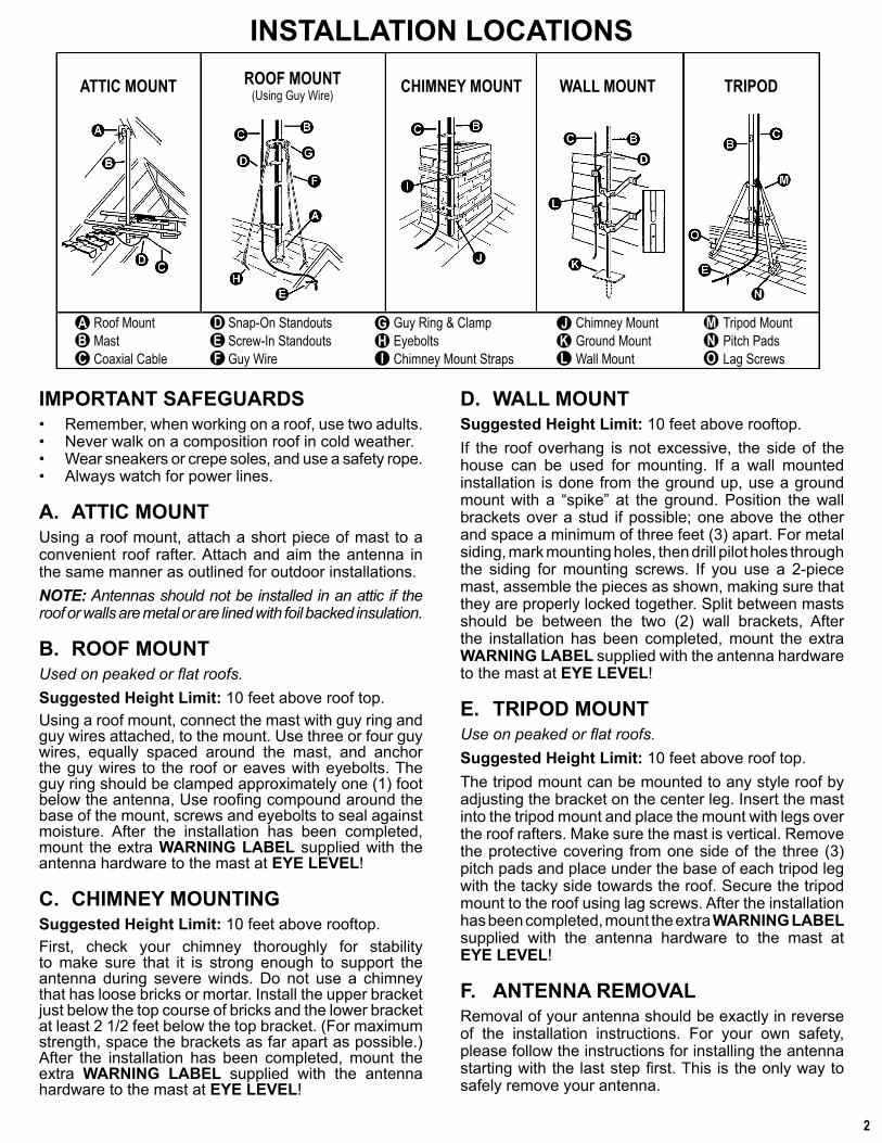
IMPORTANT SAFEGUARDS• Remember, when working on a roof, use two adults.• Never walk on a composition roof in cold weather.• Wear sneakers or crepe soles, and use a safety rope.• Always watch for power lines.
A. ATTIC MOUNTUsing a roof mount, attach a short piece of mast to a convenient roof rafter. Attach and aim the antenna in the same manner as outlined for outdoor installations. NOTE: Antennas should not be installed in an attic if the roof or walls are metal or are lined with foil backed insulation.
B. ROOF MOUNTUsed on peaked or fl at roofs.Suggested Height Limit: 10 feet above roof top.Using a roof mount, connect the mast with guy ring and guy wires attached, to the mount. Use three or four guy wires, equally spaced around the mast, and anchor the guy wires to the roof or eaves with eyebolts. The guy ring should be clamped approximately one (1) foot below the antenna, Use roofi ng compound around the base of the mount, screws and eyebolts to seal against moisture. After the installation has been completed, mount the extra WARNING LABEL supplied with the antenna hardware to the mast at EYE LEVEL!
C. CHIMNEY MOUNTINGSuggested Height Limit: 10 feet above rooftop.First, check your chimney thoroughly for stability to make sure that it is strong enough to support the antenna during severe winds. Do not use a chimney that has loose bricks or mortar. Install the upper bracket just below the top course of bricks and the lower bracket at least 2 1/2 feet below the top bracket. (For maximum strength, space the brackets as far apart as possible.) After the installation has been completed, mount the extra WARNING LABEL supplied with the antenna hardware to the mast at EYE LEVEL!
D. WALL MOUNTSuggested Height Limit: 10 feet above rooftop.If the roof overhang is not excessive, the side of the house can be used for mounting. If a wall mounted installation is done from the ground up, use a ground mount with a “spike” at the ground. Position the wall brackets over a stud if possible; one above the other and space a minimum of three feet (3) apart. For metal siding, mark mounting holes, then drill pilot holes through the siding for mounting screws. If you use a 2-piece mast, assemble the pieces as shown, making sure that they are properly locked together. Split between masts should be between the two (2) wall brackets, After the installation has been completed, mount the extra WARNING LABEL supplied with the antenna hardware to the mast at EYE LEVEL!
E. TRIPOD MOUNTUse on peaked or fl at roofs.Suggested Height Limit: 10 feet above roof top.The tripod mount can be mounted to any style roof by adjusting the bracket on the center leg. Insert the mast into the tripod mount and place the mount with legs over the roof rafters. Make sure the mast is vertical. Remove the protective covering from one side of the three (3) pitch pads and place under the base of each tripod leg with the tacky side towards the roof. Secure the tripod mount to the roof using lag screws. After the installation has been completed, mount the extra WARNING LABEL supplied with the antenna hardware to the mast at EYE LEVEL!
F. ANTENNA REMOVALRemoval of your antenna should be exactly in reverse of the installation instructions. For your own safety, please follow the instructions for installing the antenna starting with the last step fi rst. This is the only way to safely remove your antenna.
INSTALLATION LOCATIONS
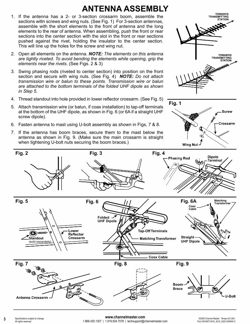
1. If the antenna has a 2- or 3-section crossarm boom, assemble the sections witln screws and wing nuts. (See Fig. 1) For 3-section antennas, assemble with the short elements to the front of antenna and the Iong elements to the rear of antenna. When assembling, push the front or rear sections into the center section with the slot in the front or rear sections pushed against the rivet, holding the insulator to the center section. This will Iine up the holes for the screw and wing nut.
2. Open alI elements on the antenna. NOTE: The elements on this antenna are tightly riveted. To avoid bending the elements while opening, grip the elements near the rivets. (See Figs. 2 & 3)
3. Swing phasing rods (riveted to center section) into position on the front section and secure with wing nuts. (See Fig. 4) NOTE: Do not attach transmission wire or balun to these points. Transmission wire or balun are attached to the bottom terminals of the folded UHF dipole as shown in Step 5.
4. Thread standout into hole provided in Iower refl ector crossarm. (See Fig. 5)
5. Attach transmission wire (or balun, if coax installation) to tap-off terminals at the bottom of the UHF dipole, as shown in Fig. 6 (or 6A if a straight UHF screw dipole).
6. Fasten antenna to mast using U-bolt assembly as shown in Figs, 7 & 8.
7. If the antenna has boom braces, secure them to the mast below the antenna as shown in Fig. 9. (Make sure the main crossarm is straight when tightening U-bolt nuts securing the boom braces.)
ANTENNA ASSEMBLY
Standout(sold separately)
www.channelmaster.com1.866.430.1307 | 1.919.934.7078 | [email protected]
©2009 Channel Master. Tempe AZ USA.Pub CM.INST.3016_3018_3020.20090413
Specifi cations subject to change. All rights reserved.
3
HIGH-DEFINIT ION TELEVISION
ADVANTAGEADVANTAGEMEDIANO Y LARGO ALCANCE ANTENAS DE TELEVISIÓNMEDIANO Y LARGO ALCANCE ANTENAS DE TELEVISIÓNHD DIGITAL / VHF / UHF / FMHD DIGITAL / VHF / UHF / FM
Hasta
6060Millas
mejor para
LARGA DISTANCIA
3018
Modelos3016, 3018
and 3020INSTRUCCIONES DE INSTALACIÓNINSTRUCCIONES DE INSTALACIÓN
3016
3020Hasta
100100Millas
mejor para
LARGA DISTANCIA
Hasta
4545Millas
mejor para
MEDIANO DISTANCIA
www.channelmaster.com
ADVERTENCIA: Instalar este producto cerca de líneas eléctricas es PELIGROSO! Por su seguridad, lea el folleto incluido antes de empezar su instalación.
1
A. USEFUL INSTALLATION TOOLS• Large and small blade screwdrivers• Adjustable Wrench• Wire Cutters• Pliers
B. WHERE TO MOUNT YOUR ANTENNA
Your antenna can be mounted on either the chimney, the root or on an outside wall or in an attic. Choose the method that best suits your particular location.
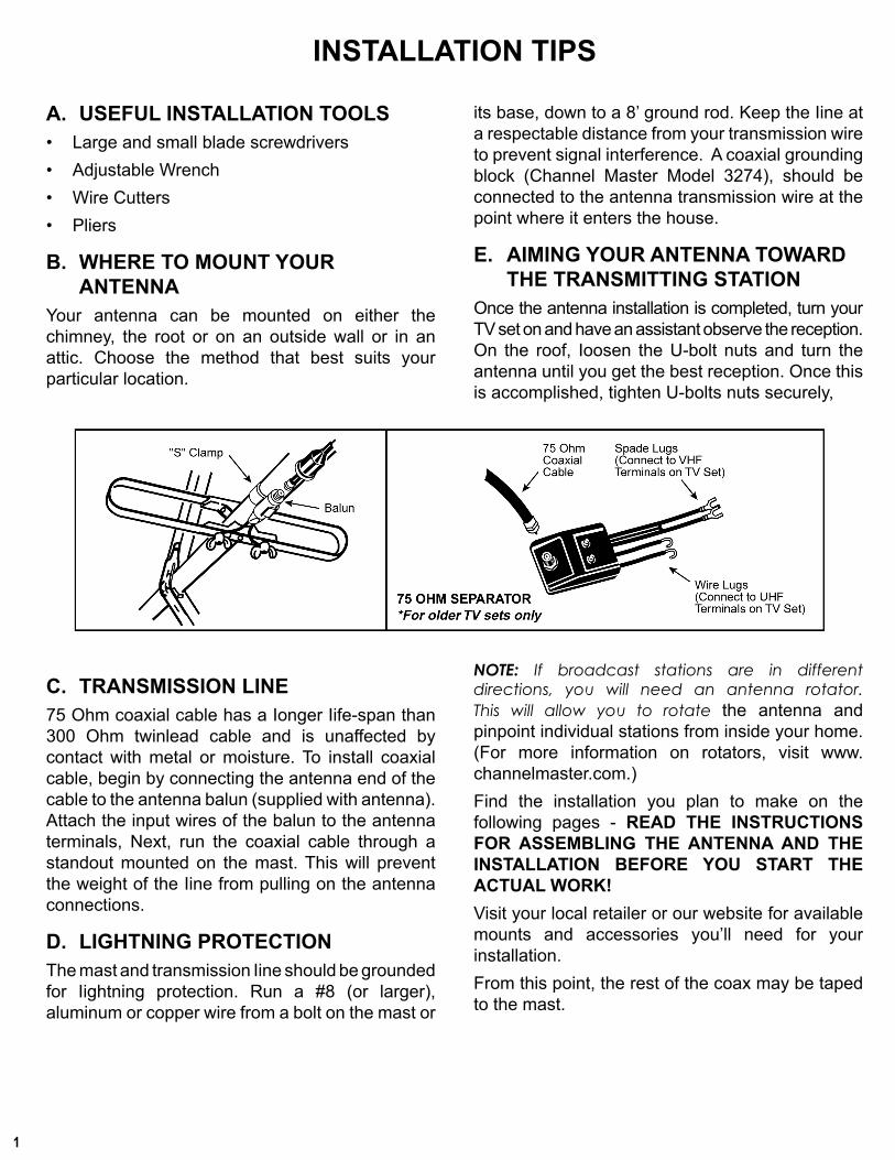
C. TRANSMISSION LINE75 Ohm coaxial cable has a Ionger Iife-span than 300 Ohm twinlead cable and is unaffected by contact with metal or moisture. To install coaxial cable, begin by connecting the antenna end of the cable to the antenna balun (supplied with antenna). Attach the input wires of the balun to the antenna terminals, Next, run the coaxial cable through a standout mounted on the mast. This will prevent the weight of the Iine from pulling on the antenna connections.
D. LIGHTNING PROTECTIONThe mast and transmission Iine should be grounded for Iightning protection. Run a #8 (or larger), aluminum or copper wire from a bolt on the mast or
its base, down to a 8’ ground rod. Keep the Iine at a respectable distance from your transmission wire to prevent signal interference. A coaxial grounding block (Channel Master Model 3274), should be connected to the antenna transmission wire at the point where it enters the house.
E. AIMING YOUR ANTENNA TOWARD THE TRANSMITTING STATION
Once the antenna installation is completed, turn your TV set on and have an assistant observe the reception. On the roof, Ioosen the U-bolt nuts and turn the antenna until you get the best reception. Once this is accomplished, tighten U-bolts nuts securely,
NOTE: If broadcast stations are in different directions, you will need an antenna rotator. This will allow you to rotate the antenna and pinpoint individual stations from inside your home. (For more information on rotators, visit www.channelmaster.com.)Find the installation you plan to make on the following pages - READ THE INSTRUCTIONS FOR ASSEMBLING THE ANTENNA AND THE INSTALLATION BEFORE YOU START THE ACTUAL WORK!Visit your local retailer or our website for available mounts and accessories you’ll need for your installation.From this point, the rest of the coax may be taped to the mast.
INSTALLATION TIPSÁTICO
DE MONTAJETECHO DE MONTAJE
(Uso de Guy Wire) CHIMENEA MONTE DE MONTAJE EN PARED TRÍPOD
Tejado monte Mástil Cable coaxial
Snap-on destacan Tornillo de las destacan Alambre guy
Anillo de sujeción y guyCáncamos Chimenea monte correas
Chimenea monte Monte terreno De montaje en pared
Trípode monte Pitch blocs Tirafondos
2
IMPORTANTES MEDIDAS DE SEGURIDAD• Recuerde, cuando se trabaja en un techo, utilice dos adultos. • Nunca camine sobre el techo de una composición en frío. • Use zapatillas o crepé soles, y utilizar una cuerda de seguridad. • Siempre atentos a las líneas eléctricas.
A. ÁTICO MONTEEl uso de un techo de montaje, adjuntar un breve trozo de mástil a una viga del techo. Conecte la antena y el objetivo de la misma manera como se indica para instalaciones al aire libre. NOTA: Las antenas no deben ser instalados en un ático si el techo o las paredes son de metal o revestidas con lámina de aislamiento respaldada.
B. TECHO DE MONTAJEUtilizado en picos o techos planos.Sugiere Altura Límite: 10 pies por encima de la azotea.El uso de un techo de montar, conectar con el mástil tipo anillo y cables tipo, a la montura. Uso de tres o cuatro cables tipo, igualmente espaciados alrededor del mástil, el tipo de anclaje y los cables en el techo o aleros con cáncamos. El tipo anillo deben sujetarse alrededor de un (1) pies por debajo de la antena, la utilización de techo compuesto alrededor de la base de la montaña, tornillos y cáncamos para sellar contra la humedad. Después de la instalación se ha completado, monte LA ETIQUETA DE ADVERTENCIA adicional suministrada con el hardware de la antena al mástil AL NIVEL DE LOS OJOS!
C. CHIMENEA DE MONTAJE Sugiere Altura Límite: 10 pies por encima de la azotea.En primer lugar, revise su chimenea fondo de estabilidad para asegurarse de que es lo sufi cientemente fuerte como para apoyar la antena durante vientos severos. No use una chimenea que suelta los ladrillos o mortero. Instale la parte superior del soporte justo por debajo de la parte superior del curso inferior de los ladrillos y el soporte, al menos, 2 1 / 2 pies por debajo de la abrazadera superior. (Para conseguir la máxima fuerza, el espacio entre paréntesis tan distantes como sea posible.) Después de la instalación se ha completado, monte LA ETIQUETA DE ADVERTENCIA adicional suministrada con el hardware de la antena al mástil AL NIVEL DE LOS OJOS!
D. DE MONTAJE EN PAREDSugiere Altura Límite: 10 pies por encima de la azotea.Si el techo de pendiente no es excesiva, el lado de la casa puede ser usado para el montaje. Si una instalación mural se hace de la tierra para arriba, use un terreno de montaje con un “pico” en el terreno. Posición de la pared entre paréntesis durante un semental, si es posible, uno encima del otro y el espacio de un mínimo de tres pies (3) de separación. Para el revestimiento de metal, marca de agujeros de montaje, entonces piloto de perforación a través de los agujeros para tornillos de montaje de revestimiento. Si utiliza un mástil de 2 piezas, las piezas tal y como se muestra, asegurándose de que estén debidamente bloqueados juntos. Separación entre postes debe ser entre los dos (2) soportes de pared, después de la instalación se ha completado, monte LA ETIQUETA DE ADVERTENCIA adicional suministrada con el hardware de la antena al mástil AL NIVEL DE LOS OJOS!
E. MONTURA PARA TRÍPODE Su uso en techos planos o máximo. Sugiere Altura Límite: 10 pies por encima de la azotea.La montura para trípode se puede montar en cualquier estilo techo ajustando el soporte en el centro de la pierna. Introduzca el mástil en la montura para trípode y el lugar de montaje con las piernas sobre el techo de vigas. Asegúrese de que el mástil vertical. Quite la cubierta protectora de un lado de los tres (3) pastillas de brea y de lugar en la base de cada pata del trípode con el lado pegajoso hacia el techo. Asegure el trípode de montaje en el techo mediante tirafondos. Después de la instalación se ha completado, monte LA ETIQUETA DE ADVERTENCIA adicional suministrado con el hardware de la antena en el mástil NIVEL DE LOS OJOS!
F. ANTENA ELIMINACIÓN Eliminación de la antena debe ser exactamente al revés de las instrucciones de instalación. Por su propia seguridad, por favor, siga las instrucciones para la instalación de la antena a partir de la última etapa en primer lugar. Esta es la única manera de eliminar la antena.
LUGARES DE INSTALACIÓN
![· Web view– ceturtdaļviļņa vertikālā antena [“ground plane” tipa antena], – antena ar parazītelementiem [jagi],](https://img.pdfslide.tips/doc/110x75/5aae6cbd7f8b9adb688c5507/view-ceturtdalvilna-vertikala-antena-ground-plane-tipa-antena-.jpg)