Embed Size (px)
Citation preview

MRI Free Pacemaker: Why & How?
아주대학교 병원 순환기 내과
황 교 승

Magnetic Resonance Imaging (MRI)
“Gold standard for imaging soft tissues in the body”

• Electronic Devices: - Pacemakers - implantable cardioverter defibrillators (ICD) - neurostimulation systems - cochlear implants - drug infusion pump - bone fusion stimulator
• Pacemaker or ICD patients: - generally older and sicker - between a 50 and 75% of having a clinical indication for magnetic resonance imaging (MRI) over the lifetime of the device
Pacing Clin Electrophysiol 2005;28:326–8
Electronic Devices and MRI
Principles of Magnetic Resonance
Gx,Gy,Gz
B1
Bo

Static Field
Gradient Field
RF Field
Three Powerful Fields

Spin up
Spin down
Bo
Signal
Signal amplification & processing
Spin down Spin up
Magnetic Resonance Imaging (MRI)
* The signal used in MRI: Protons (H) of water and fat molecules

• T (Tesla), G (Gauss), Wb/m² • 1T = 1Wb/m² = 10,000G • 자기장에서 1T의 크기는 자기장에 수직으로 매초 1m의 속도로 움직이는 1C의 전하가 1N의 힘을 받는 것을 의미 1T = (1N/C)/(1m/s) = 1N/Am • Coulomb's law (쿨롱의 법칙) : F:두 자극 사이에 작용하는 힘[N], k:비례상수(k=1/(4πμ0)), r:두 자극 사이의 거리[m], m1,m2:자하[Wb]. μ0:진공의 투자율(μ0=4π×10-7[H/m]), μR:비투자율[단위없음]
Magnetic Field (자기장, 磁氣場)

N
S
Magnetic Field (자기장, 磁氣場)

Magnetic Field (자기장, 磁氣場)

• Specific absorption rate (SAR) = the power absorbed per unit mass of tissue : key variable in determining patient heating potential in an MRI • Application of RF energy during MR scanning is adjusted to avoid producing: - a core temperature rise in excess of 1°C - localized heating greater than 38°C in the head 39°C in the trunk 40°C in the extremities • SAR and heating is decreased by changing MR parameters - increasing the RF repetition time - adjusting flip angles - changing matrix size • SAR as a poor indicator of MRI implant heating across different MR systems with different software
Europace 2010;12:947–51
Invest Radiol 2005;40:773–6
Magnetic field (자기장, 磁氣場)

A Potential Interactions Between Implantable Cardiac Devices and MRI
• Mechanical forces on ferromagnetic components • RF-induced heating of leads • Unintended cardiac stimulation • Interference with pacemaker function • Electrical reset

Potential Adverse Interactions Between Pacemakers and MRI
• Heating • Induction of ventricular fibrillation • Rapid atrial pacing • Pacing at multiples of the RF pulse and associated rapid ventricular pacing • Reed switch malfunction • Asynchronous pacing • Inhibition of pacing output • Alteration of programming with potential damage to the pacemaker circuitry • Movement of the device
J Am Coll Cardiol 2004;43:1315–24

Interaction Between Pacemakers and MRI

Pacing Clin Electrophysiol 2001;24:199–205
• Force and torque A 1.5-T MRI scanner on pacemakers and ICDs In pacemakers - Force: 0.05 to 3.6 N - measured acceleration: lower than the gravity of the earth (< 9.81 N/kg) - torque levels: < or = 2 from a scale of 6 In ICDs - Force: 1.03-5.85 N - Acceleration: 9.5-34.2 N/kg - Torque: 5-6 out of 6 * Modern pacemakers present no safety risk with respect to magnetic force and torque induced by the static magnetic field of a 1.5-T MRI scanner. However, ICD devices may still pose problems due to strong magnetic force and torque
Interaction Between Pacemakers and MRI

• Lead tip heating:
Fifty-four patients underwent a total of 62 MRI examinations at 1.5-T - No limitation of the type of MRI examination (various whole-body averaged SAR of RF power: cardiac, vascular, and general MRI studies) - No restrictions on the type of pacemaker present - 40/107 (37%) leads: pacing threshold changes - 10 (9.4%) leads: significant change (defined as a change >1 voltage or pulse– width increment or decrement) - Two leads (1.9%) required a change in programmed output.
J Am Coll Cardiol 2004;43:1315–24
Interaction Between Pacemakers and MRI

• Lead tip heating: Extrathoracic MRI at 1.5 T in the Presence of Pacemakers in Non–Pacemaker-Depen dent Patients: A Prospective Study With 115 Examinations - limiting the SAR to 1.5 W/kg - excluding the thoracic spine, heart, and breasts - The total active scan time: limited to 30 min - cardiac troponins: increased in 4 of 114 examinations; in one case these increases were associated with a significant increase in pacing capture threshold. - pacing-capture threshold changes ≥1.0 V: in 6 cases - Possible long-term effects of scanning (> 3 month follow-up) : in two cases (increased pacing capture threshold)
Circulation 2006;114:1285–92
Interaction Between Pacemakers and MRI

Lead tip Heating

Lead tip Heating
Tesla Maximal Temperature (T) Conditions
0.5T 23.5C Pacemaker/leads in the isocenter of RF cloil
SAR 1.3W/kg
1.5T 63.1C Pacemaker/leads in the center of RF cloils
Sommer T. Radiology 2000 Achenbach S. Am Heart 1997
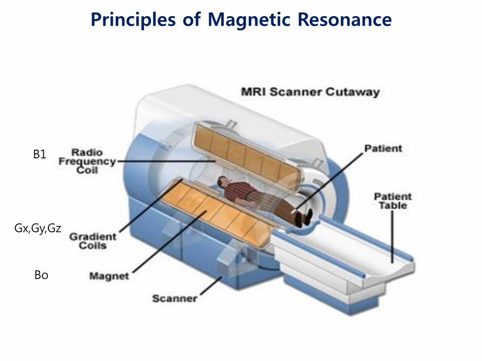
• Reed switches - If the reed switches were oriented parallel to the magnetic fields : closed at 1.0±0.2 mT opened at 0.7±0.2 mT. - In 50% of all tested orientations: : closed in low magnetic fields (< 50 mT) opened in high magnetic fields (> 200 mT), Pacing Clin Electrophysiol 2002;25:1419–23
- During extrathoracic MRI at 1.5 T -The reed switch: inactivated in 21/47 (44.7%) of patients
Interaction Between Pacemakers and MRI
Circulation 2006;114:1285–92

• Electrical reset: - If reset occurs concomitant with an open reed switch, bradycardia/asystole may occur in patients with low intrinsic heart rates as a result of inhibition of pacemaker output by time-varying gradient fields. - The default pacing mode may not provide adequate functionality for some patients - occurred in 7/115 (6.1%) examinations during extrathoracic MRI at 1.5 T
Europace 2008;10:336–46
Circulation 2006;114:1285–92
A Potential Interactions Between Implantable Cardiac Devices and MRI

Gimbel J R Europace 2009;11:1241-1242
Unexpected Asystole During 3T MRI of a Pacemaker-dependent Patient With a ‘Modern’ Pacemaker
Brain MRI, VOO 60 ppm at maximum output in a bipolar configuration
gradient field application

Gradient Waveform
Am
plit
ude
0.4 ms
500 ms – 750 ms
Pacing Pulse
Time
~ 0.005 ms
Gradient Induced Pulse
Gradient Induced Pulse
Gradient Induced Stimulation Mechanism

Gradient-induced High Rate Pacing
Start of Scan
EKG
Pulse Ox
Canine Test

Indication for MRI in Patients With Cardiac Device
Europace (2012) 14, 631–637

Strategies for performing safe MRI procedures - Programming the pacemaker device subthreshold - Asynchronous mode - Programming to a bipolar lead configuration if possible - Non–pacemaker-dependent patients - Limiting exposure to RF power during MRI - Only performing MRI examinations if the pulse generator is positioned outside of the bore of the MR system - Explanting the pulse generator prior to MRI
Eur Heart J 2001;22:113–24
Interaction Between Pacemakers and MRI

Positioning Criteria
iso-center
iso-center
C1
T12

Heart Rhythm 2009;6:138–43
Programming for performing safe MRI procedures
• In pacemaker-dependent patients: asynchronous, dedicated pacing mode • In non-pacemaker-dependent patients: - non-tracking ventricular or dual-chamber inhibited pacing mode - deactivation of rate response PVC response ventricular sense response conducted AF response magnet mode • Deactivation of tachyarrhythmia monitoring • SAR < 2.0 W/kg
Pacemakers and MRI

Heart Rhythm 2009;6:138–43
• Exclusion for performing safe MRI procedures
- Older devices (manufactured before 2000) - Patients with < 6 weeks time since device implant and those with no fixation - Prone to healing (e.g. non-transvenous epicardial and capped leads) - Pacemaker-dependent patients with ICDs
Pacemakers and MRI

• MRI at 1.5 T in patients with cardiac devices resulted in no device or lead failures
Am J Cardiol. 2012 Dec 1;110(11):1631-6
• Patients with pacemakers have been successfully imaged using MRI operating at static field strengths ranging from 0.35 T to 1.5-T without any clinically adverse events
Coman JA J Am Coll Cardiol 2001
Interaction Between Pacemakers and MRI
• Cardiac MRI may be performed safely when limiting SAR(< 1.5 W/kg), appropriately monitoring patients, and following device reprogramming. Cardiac MR delivers good image quality and diagnostic value in patients with right sided device
Am Heart J 2011;161:1096-105

• 1500 scans of patients with pacemakers or ICDs in the literature in any form • Reputable venues have included a grand total of 344 patients: 81 at a field strength of 0.5 T 13 at a field strength of 2.0 T 250 at a field strength of 1.5 T
Europace (2012) 14, 631–637
Pacemakers and MRI
Europace 2010;12: 915–7

New Pacemaker Design for MRI
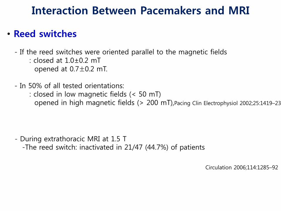
• The leads were modified to reduce RF lead tip heating • Internal circuits were changed to reduce the potential for cardiac stimulation • The amount of ferromagnetic materials was limited • Internal circuit protection was improved to prevent disruption of the internal power supply • The reed switch was replaced by a Hall sensor • A dedicated programming care pathway was developed to facilitate the choice between asynchronous versus nonstimulation modes, increase the pacing output to 5.0 V/1.0 ms during MRI scanning, prevent programming the MRI mode if the device failed any of the 7 system integrity checks, and facilitate restoration of prescan program states and values
Heart Rhythm 2010;8:65–73
1. Pacemaker and both leads implanted >6 weeks
2. Pectoral implantation
3. No other active pacing or ICD devices or leads
4. No abandoned leads, lead extenders, or adapters
5. Leads electrically intact, with stable and normal function
6. Lead impedance between 200 and 1,500 Ω
7. Capture threshold <2.0 V at 0.4 ms
Pacing System Integrity Checks
Heart Rhythm 2010;8:65–73

• The ability of new pacemaker system to be exposed in a controlled fashion to MRI in a 1.5 T scanner without adverse impact on patient outcomes or pacemaker system function Heart Rhythm 2010;8:65–73
• The feasibility and safety of new technology compare favorably with those of the conventional technique
Heart Rhythm 2010;7:750–4
• The new pacemaker system is safe and effective in the 1.5 T MRI environment without positioning restrictions for MRI scans or limitations of body parts scanned Rod Gimbel J et al. Heart Rhythm. 2013 Jan 17
New Pacemaker Design for MRI

Conclusions
• MRI of pacemaker patients can be performed with an acceptable risk-benefit ratio under controlled conditions and by taking both MR- and pacemaker-related precautions • New devices for MRI have been adequately evaluated only at field strengths of up to 1.5 T and—as 3.0 T MR scanners come into broader use—there is an urgent need to evaluate the safety of scanning these devices at higher field strengths

감사합니다
![PACEMAKER 발표용[1].ppt 최종](https://img.pdfslide.tips/doc/110x75/541ea6627bef0afc188b47bd/pacemaker-1ppt-.jpg)