Embed Size (px)
Citation preview
NANOVERB 2
QUICKSTART GUIDE ENGLISH (3 - 6)
GUÍA DE INICIO RÁPIDO
ESPAÑOL (7 - 10)
GUIDE D'UTILISATION RAPIDE FRANÇAIS (11 - 14)
GUIDA RAPIDA
ITALIANO (15 - 18)
KURZANLEITUNG DEUTSCH (19 – 22)

3
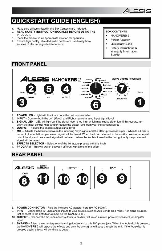
QUICKSTART GUIDE (ENGLISH) 1. Make sure all items listed in the Box Contents are included. 2. READ SAFETY INSTRUCTION BOOKLET BEFORE USING THE
PRODUCT. 3. Place the product in an appropriate location for operation. 4. Ensure high quality, shielded audio cables are used away from
sources of electromagnetic interference.
FRONT PANEL
1. POWER LED – Light will illuminate once the unit is powered on 2. INPUT – Controls both the Left (Mono) and Right channel analog input signal level 3. SIGNAL LED – LED will light up if the signal level is too high which may cause distortion. If this occurs, turn
down the Input control knob and/or reduce the output level from your instrument source 4. OUTPUT – Adjusts the analog output signal level 5. MIX – Adjusts the balance between the incoming "dry" signal and the effect-processed signal. When this knob is
turned to the far left, no processed signal will be heard. When the knob is turned to the middle position, an equal mix of the dry and processed signal will be heard. When the knob is turned to the far right, only the processed signal will be heard
6. EFFECTS SELECTOR – Select one of the 16 factory presets with this knob 7. PROGRAM – This will switch between different variations of the effect
REAR PANEL
8. POWER CONNECTOR – Plug the included AC adapter here (9v AC 500mA) 9. INPUT – Connect the ¼” unbalanced inputs to your source, such as Aux Sends on a mixer. For mono sources,
just connect to the Left (Mono) input on the NANOVERB 2 10. OUTPUT – Connect the ¼” unbalanced outputs to an Aux Return on a mixer, powered speakers, or amplifer
input 11. BYPASS – Attach a momentary (non-latching) footswitch to this 1/4" phone jack. When the footswitch is pressed,
the NANOVERB 2 will bypass the effects and only the dry signal will pass through the unit. If the footswitch is pressed again, effects will continue to output
BOX CONTENTS NANOVERB 2 Power Adapter Quickstart Guide Safety Instructions &
Warranty Information Booklet
4
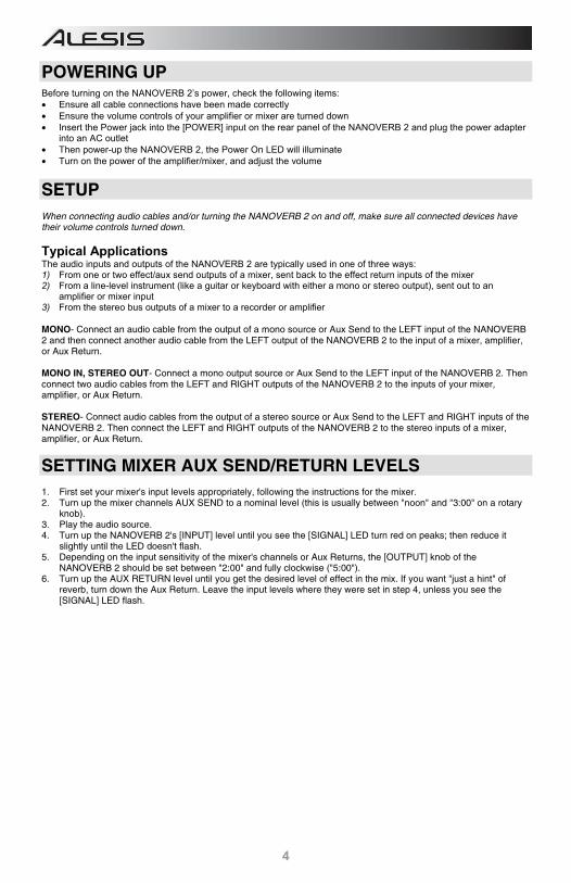
POWERING UP Before turning on the NANOVERB 2’s power, check the following items: • Ensure all cable connections have been made correctly • Ensure the volume controls of your amplifier or mixer are turned down • Insert the Power jack into the [POWER] input on the rear panel of the NANOVERB 2 and plug the power adapter
into an AC outlet • Then power-up the NANOVERB 2, the Power On LED will illuminate • Turn on the power of the amplifier/mixer, and adjust the volume
SETUP When connecting audio cables and/or turning the NANOVERB 2 on and off, make sure all connected devices have their volume controls turned down.
Typical Applications The audio inputs and outputs of the NANOVERB 2 are typically used in one of three ways: 1) From one or two effect/aux send outputs of a mixer, sent back to the effect return inputs of the mixer 2) From a line-level instrument (like a guitar or keyboard with either a mono or stereo output), sent out to an
amplifier or mixer input 3) From the stereo bus outputs of a mixer to a recorder or amplifier MONO- Connect an audio cable from the output of a mono source or Aux Send to the LEFT input of the NANOVERB 2 and then connect another audio cable from the LEFT output of the NANOVERB 2 to the input of a mixer, amplifier, or Aux Return. MONO IN, STEREO OUT- Connect a mono output source or Aux Send to the LEFT input of the NANOVERB 2. Then connect two audio cables from the LEFT and RIGHT outputs of the NANOVERB 2 to the inputs of your mixer, amplifier, or Aux Return. STEREO- Connect audio cables from the output of a stereo source or Aux Send to the LEFT and RIGHT inputs of the NANOVERB 2. Then connect the LEFT and RIGHT outputs of the NANOVERB 2 to the stereo inputs of a mixer, amplifier, or Aux Return.
SETTING MIXER AUX SEND/RETURN LEVELS 1. First set your mixer's input levels appropriately, following the instructions for the mixer. 2. Turn up the mixer channels AUX SEND to a nominal level (this is usually between "noon" and "3:00" on a rotary
knob). 3. Play the audio source. 4. Turn up the NANOVERB 2's [INPUT] level until you see the [SIGNAL] LED turn red on peaks; then reduce it
slightly until the LED doesn't flash. 5. Depending on the input sensitivity of the mixer's channels or Aux Returns, the [OUTPUT] knob of the
NANOVERB 2 should be set between "2:00" and fully clockwise ("5:00"). 6. Turn up the AUX RETURN level until you get the desired level of effect in the mix. If you want "just a hint" of
reverb, turn down the Aux Return. Leave the input levels where they were set in step 4, unless you see the [SIGNAL] LED flash.
5
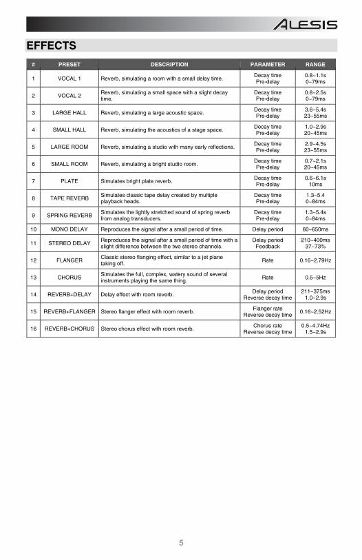
EFFECTS
# PRESET DESCRIPTION PARAMETER RANGE
1 VOCAL 1 Reverb, simulating a room with a small delay time. Decay timePre-delay
0.8~1.1s 0~79ms
2 VOCAL 2 Reverb, simulating a small space with a slight decay time.
Decay timePre-delay
0.8~2.5s 0~79ms
3 LARGE HALL Reverb, simulating a large acoustic space. Decay timePre-delay
3.6~5.4s 23~55ms
4 SMALL HALL Reverb, simulating the acoustics of a stage space. Decay timePre-delay
1.0~2.9s 20~45ms
5 LARGE ROOM Reverb, simulating a studio with many early reflections. Decay timePre-delay
2.9~4.5s 23~55ms
6 SMALL ROOM Reverb, simulating a bright studio room. Decay timePre-delay
0.7~2.1s 20~45ms
7 PLATE Simulates bright plate reverb. Decay timePre-delay
0.6~6.1s 10ms
8 TAPE REVERB Simulates classic tape delay created by multiple playback heads.
Decay timePre-delay
1.3~5.4 0~84ms
9 SPRING REVERB Simulates the lightly stretched sound of spring reverb from analog transducers.
Decay timePre-delay
1.3~5.4s 0~84ms
10 MONO DELAY Reproduces the signal after a small period of time. Delay period 60~650ms
11 STEREO DELAY Reproduces the signal after a small period of time with a slight difference between the two stereo channels.
Delay periodFeedback
210~400ms 37~73%
12 FLANGER Classic stereo flanging effect, similar to a jet plane taking off.
Rate 0.16~2.79Hz
13 CHORUS Simulates the full, complex, watery sound of several instruments playing the same thing.
Rate 0.5~5Hz
14 REVERB+DELAY Delay effect with room reverb. Delay period
Reverse decay time 211~375ms
1.0~2.9s
15 REVERB+FLANGER Stereo flanger effect with room reverb. Flanger rateReverse decay time
0.16~2.52Hz
16 REVERB+CHORUS Stereo chorus effect with room reverb. Chorus rate
Reverse decay time 0.5~4.74Hz
1.5~2.9s
6
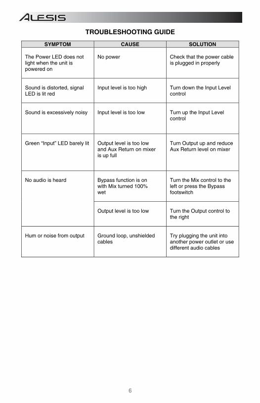
TROUBLESHOOTING GUIDE
SYMPTOM CAUSE SOLUTION The Power LED does not light when the unit is powered on
No power
Check that the power cable is plugged in properly
Sound is distorted, signal LED is lit red
Input level is too high
Turn down the Input Level control
Sound is excessively noisy
Input level is too low
Turn up the Input Level control
Green “Input” LED barely lit
Output level is too low and Aux Return on mixer is up full
Turn Output up and reduce Aux Return level on mixer
No audio is heard
Bypass function is on with Mix turned 100% wet
Turn the Mix control to the left or press the Bypass footswitch
Output level is too low
Turn the Output control to the right
Hum or noise from output
Ground loop, unshielded cables
Try plugging the unit into another power outlet or use different audio cables
7
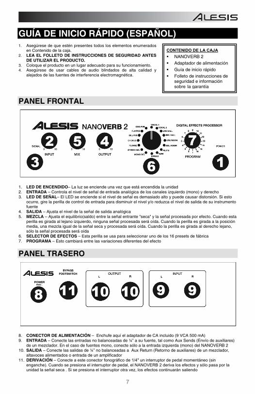
GUÍA DE INICIO RÁPIDO (ESPAÑOL) 1. Asegúrese de que estén presentes todos los elementos enumerados
en Contenido de la caja. 2. LEA EL FOLLETO DE INSTRUCCIONES DE SEGURIDAD ANTES
DE UTILIZAR EL PRODUCTO. 3. Coloque el producto en un lugar adecuado para su funcionamiento. 4. Asegúrese de usar cables de audio blindados de alta calidad y
alejados de las fuentes de interferencia electromagnética.
PANEL FRONTAL
1. LED DE ENCENDIDO– La luz se enciende una vez que está encendida la unidad 2. ENTRADA – Controla el nivel de señal de entrada analógica de los canales izquierdo (mono) y derecho 3. LED DE SEÑAL– El LED se enciende si el nivel de señal es demasiado alto y puede causar distorsión. Si esto
ocurre, gire la perilla de control de entrada para disminuir el nivel y/o reduzca el nivel de salida de su instrumento fuente
4. SALIDA – Ajusta el nivel de la señal de salida analógica 5. MEZCLA – Ajusta el equilibrio(saldo) entre la señal entrante "seca" y la señal procesada por efecto. Cuando esta
perilla es girada al lejano izquierdo, ninguna señal procesada será oída. Cuando la perilla es girada a la posición media, una mezcla igual de la señal seca y procesada será oída. Cuando la perilla es girada al derecho lejano, sólo la señal procesada será oída
6. SELECTOR DE EFECTOS – Esta perilla se usa para seleccionar uno de los 16 presets de fábrica 7. PROGRAMA – Esto cambiará entre las variaciones diferentes del efecto
PANEL TRASERO
8. CONECTOR DE ALIMENTACIÓN – Enchufe aquí el adaptador de CA incluido (9 VCA 500 mA) 9. ENTRADA – Conecte las entradas no balanceadas de ¼” a su fuente, tal como Aux Sends (Envío de auxiliares)
de un mezclador. En el caso de fuentes mono, conecte sólo a la entrada izquierda (mono) del NANOVERB 2 10. SALIDA – Conecte las salidas de ¼” no balanceadas a Aux Return (Retorno de auxiliares) de un mezclador,
altavoces alimentados o entrada de un amplificador 11. DERIVACIÓN – Conecte a este conector fonográfico de 1/4" un interruptor de pedal momentáneo (sin
enganche). Cuando se presiona el interruptor de pedal, el NANOVERB 2 deriva los efectos y sólo pasa por la unidad la señal seca . Si se presiona el interruptor otra vez, los efectos continuarán saliendo
CONTENIDO DE LA CAJA NANOVERB 2 Adaptador de alimentación Guía de inicio rápido Folleto de instrucciones de
seguridad e información sobre la garantía
8
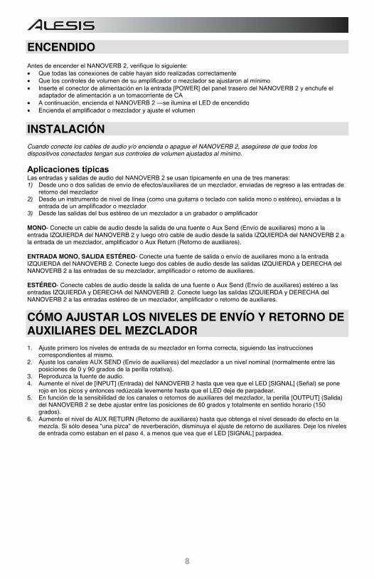
ENCENDIDO Antes de encender el NANOVERB 2, verifique lo siguiente: • Que todas las conexiones de cable hayan sido realizadas correctamente • Que los controles de volumen de su amplificador o mezclador se ajustaron al mínimo • Inserte el conector de alimentación en la entrada [POWER] del panel trasero del NANOVERB 2 y enchufe el
adaptador de alimentación a un tomacorriente de CA • A continuación, encienda el NANOVERB 2 —se ilumina el LED de encendido • Encienda el amplificador o mezclador y ajuste el volumen
INSTALACIÓN Cuando conecte los cables de audio y/o encienda o apague el NANOVERB 2, asegúrese de que todos los dispositivos conectados tengan sus controles de volumen ajustados al mínimo.
Aplicaciones típicas Las entradas y salidas de audio del NANOVERB 2 se usan típicamente en una de tres maneras: 1) Desde uno o dos salidas de envío de efectos/auxiliares de un mezclador, enviadas de regreso a las entradas de
retorno del mezclador 2) Desde un instrumento de nivel de línea (como una guitarra o teclado con salida mono o estéreo), enviadas a la
entrada de un amplificador o mezclador 3) Desde las salidas del bus estéreo de un mezclador a un grabador o amplificador MONO- Conecte un cable de audio desde la salida de una fuente o Aux Send (Envío de auxiliares) mono a la entrada IZQUIERDA del NANOVERB 2 y luego otro cable de audio desde la salida IZQUIERDA del NANOVERB 2 a la entrada de un mezclador, amplificador o Aux Return (Retorno de auxiliares). ENTRADA MONO, SALIDA ESTÉREO- Conecte una fuente de salida o envío de auxiliares mono a la entrada IZQUIERDA del NANOVERB 2. Conecte luego dos cables de audio desde las salidas IZQUIERDA y DERECHA del NANOVERB 2 a las entradas de su mezclador, amplificador o retorno de auxiliares. ESTÉREO- Conecte cables de audio desde la salida de una fuente o Aux Send (Envío de auxiliares) estéreo a las entradas IZQUIERDA y DERECHA del NANOVERB 2. Conecte luego las salidas IZQUIERDA y DERECHA del NANOVERB 2 a las entradas estéreo de un mezclador, amplificador o retorno de auxiliares.
CÓMO AJUSTAR LOS NIVELES DE ENVÍO Y RETORNO DE AUXILIARES DEL MEZCLADOR 1. Ajuste primero los niveles de entrada de su mezclador en forma correcta, siguiendo las instrucciones
correspondientes al mismo. 2. Ajuste los canales AUX SEND (Envío de auxiliares) del mezclador a un nivel nominal (normalmente entre las
posiciones de 0 y 90 grados de la perilla rotativa). 3. Reproduzca la fuente de audio. 4. Aumente el nivel de [INPUT] (Entrada) del NANOVERB 2 hasta que vea que el LED [SIGNAL] (Señal) se pone
rojo en los picos y entonces redúzcala levemente hasta que el LED deje de parpadear. 5. En función de la sensibilidad de los canales o retornos de auxiliares del mezclador, la perilla [OUTPUT] (Salida)
del NANOVERB 2 se debe ajustar entre las posiciones de 60 grados y totalmente en sentido horario (150 grados).
6. Aumente el nivel de AUX RETURN (Retorno de auxiliares) hasta que obtenga el nivel deseado de efecto en la mezcla. Si sólo desea "una pizca" de reverberación, disminuya el ajuste de retorno de auxiliares. Deje los niveles de entrada como estaban en el paso 4, a menos que vea que el LED [SIGNAL] parpadea.
9
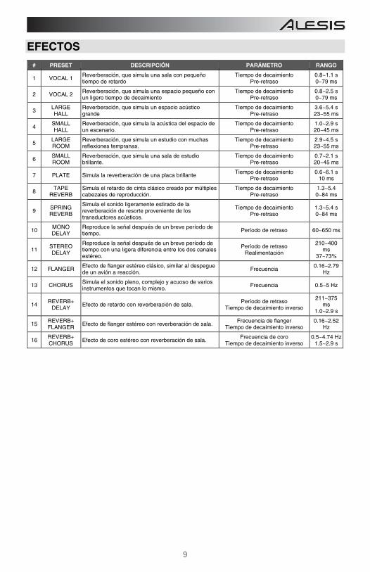
EFECTOS
# PRESET DESCRIPCIÓN PARÁMETRO RANGO 1 VOCAL 1 Reverberación, que simula una sala con pequeño
tiempo de retardoTiempo de decaimiento
Pre-retraso0.8~1.1 s 0~79 ms
2 VOCAL 2 Reverberación, que simula una espacio pequeño con un ligero tiempo de decaimiento
Tiempo de decaimientoPre-retraso
0.8~2.5 s 0~79 ms
3 LARGE HALL Reverberación, que simula un espacio acústico
grandeTiempo de decaimiento
Pre-retraso3.6~5.4 s 23~55 ms
4 SMALL HALL Reverberación, que simula la acústica del espacio de
un escenario.Tiempo de decaimiento
Pre-retraso1.0~2.9 s 20~45 ms
5 LARGE ROOM Reverberación, que simula un estudio con muchas
reflexiones tempranas.Tiempo de decaimiento
Pre-retraso2.9~4.5 s 23~55 ms
6 SMALL ROOM Reverberación, que simula una sala de estudio
brillante.Tiempo de decaimiento
Pre-retraso0.7~2.1 s 20~45 ms
7 PLATE Simula la reverberación de una placa brillante Tiempo de decaimientoPre-retraso
0.6~6.1 s 10 ms
8 TAPE
REVERB Simula el retardo de cinta clásico creado por múltiples cabezales de reproducción.
Tiempo de decaimientoPre-retraso
1.3~5.4 0~84 ms
9 SPRING REVERB
Simula el sonido ligeramente estirado de la reverberación de resorte proveniente de los transductores acústicos.
Tiempo de decaimiento Pre-retraso 1.3~5.4 s
0~84 ms 10
MONO DELAY Reproduce la señal después de un breve período de
tiempo. Período de retraso 60~650 ms
11 STEREO DELAY
Reproduce la señal después de un breve período de tiempo con una ligera diferencia entre los dos canales estéreo.
Período de retraso Realimentación
210~400 ms
37~73% 12 FLANGER Efecto de flanger estéreo clásico, similar al despegue
de un avión a reacción.Frecuencia
0.16~2.79 Hz
13 CHORUS Simula el sonido pleno, complejo y acuoso de varios instrumentos que tocan lo mismo.
Frecuencia 0.5~5 Hz
14 REVERB+ DELAY Efecto de retardo con reverberación de sala. Período de retraso
Tiempo de decaimiento inverso 211~375
ms 1.0~2.9 s
15 REVERB+ FLANGER Efecto de flanger estéreo con reverberación de sala.
Frecuencia de flangerTiempo de decaimiento inverso
0.16~2.52 Hz
16 REVERB+ CHORUS Efecto de coro estéreo con reverberación de sala.
Frecuencia de coroTiempo de decaimiento inverso
0.5~4.74 Hz 1.5~2.9 s
10
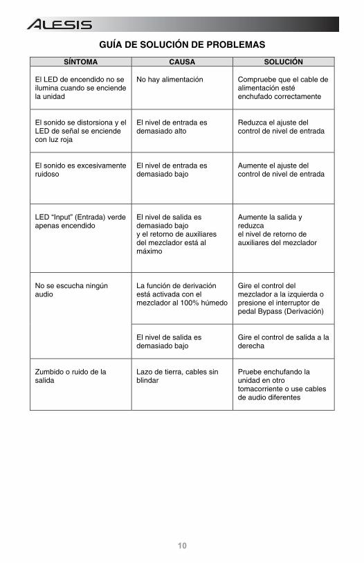
GUÍA DE SOLUCIÓN DE PROBLEMAS
SÍNTOMA CAUSA SOLUCIÓN El LED de encendido no se ilumina cuando se enciende la unidad
No hay alimentación
Compruebe que el cable de alimentación esté enchufado correctamente
El sonido se distorsiona y el LED de señal se enciende con luz roja
El nivel de entrada es demasiado alto
Reduzca el ajuste del control de nivel de entrada
El sonido es excesivamente ruidoso
El nivel de entrada es demasiado bajo
Aumente el ajuste del control de nivel de entrada
LED “Input” (Entrada) verde apenas encendido
El nivel de salida es demasiado bajo y el retorno de auxiliares del mezclador está al máximo
Aumente la salida y reduzca el nivel de retorno de auxiliares del mezclador
No se escucha ningún audio
La función de derivación está activada con el mezclador al 100% húmedo
Gire el control del mezclador a la izquierda o presione el interruptor de pedal Bypass (Derivación)
El nivel de salida es demasiado bajo
Gire el control de salida a la derecha
Zumbido o ruido de la salida
Lazo de tierra, cables sin blindar
Pruebe enchufando la unidad en otro tomacorriente o use cables de audio diferentes
11
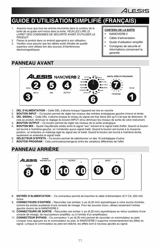
GUIDE D’UTILISATION SIMPLIFIÉ (FRANÇAIS) 1. Assurez-vous que tous les articles énumérés dans le contenu de la
boîte de ce guide sont inclus dans la boîte. VEUILLEZ LIRE LE LIVRET DES CONSIGNES DE SÉCURITÉ AVANT D'UTILISER LE PRODUIT.
2. Placez le produit dans un endroit approprié à son utilisation. 3. Veuillez vous assurer que les câbles audio blindés de qualité
supérieur sont utilisés loin des sources d’interférences électromagnétiques.
PANNEAU AVANT
1. DEL D’ALIMENTATION – Cette DEL s’allume lorsque l’appareil est mis en marche 2. BOUTON INPUT – Ce bouton permet de régler les niveaux des entrées analogiques gauche (mono) et droite 3. DEL SIGNAL – Cette DEL s’allume lorsque le niveau du signal est trop élevé afin qu’il n’ait pas de distorsion. Si
cela se produit, diminuez le réglage du bouton INPUT et/ou diminuez les niveaux de sortie de votre instrument. 4. BOUTON OUTPUT – Ce bouton permet de régler les niveaux de la sortie analogique 5. BOUTON MIX – Ajuste l'équilibre(le solde) entre le signal "sec" entrant et le signal traité d'effet. Quand ce bouton
est tourné à l'extrême-gauche, on n'entendra aucun signal traité. Quand le bouton est tourné à la moyenne position, on entendra un mélange égal du signal sec et traité. Quand le bouton est tourné à l'extrême-droite, seulement on entendra le signal traité
6. SÉLECTEUR D’EFFETS – Ce bouton permet de sélectionner un des 16 préréglages d’usine 7. BOUTON PROGRAM – Cela commutera(changera) entre les variations différentes de l'effet
PANNEAU ARRIÈRE
8. ENTRÉE D’ALIMENTATION – Ce connecteur permet de brancher le câble d’alimentation (9 V CA, 500 mA) inclus.
9. CONNECTEURS D’ENTRÉE – Raccordez ces entrées ¼ po (6,35 mm) asymétriques à votre source d’entrée, comme les sorties auxiliaires d’une console de mixage. Pour les sources mono, utilisez seulement l’entrée gauche (mono) de la NANOVERB 2.
10. CONNECTEURS DE SORTIE – Raccordez ces sorties ¼ po (6,35 mm) asymétriques au retour auxiliaire d’une console de mixage, de haut-parleurs amplifiés, ou à l’entrée d’un amplificateur.
11. CONNECTEUR BYPASS – Ce connecteur ¼ po (6,35 mm) permet de raccorder un commutateur au pied. Lorsque vous appuyez sur le commutateur au pied, le NANOVERB 2 supprime momentanément les effets du signal. Lorsque le commutateur au pied est relâché, les effets sont à nouveau ajoutés au signal.
CONTENU DE LA BOÎTE NANOVERB 2 Câble d’alimentation Guide d’utilisation simplifié Consignes de sécurité et
informations concernant la garantie
12
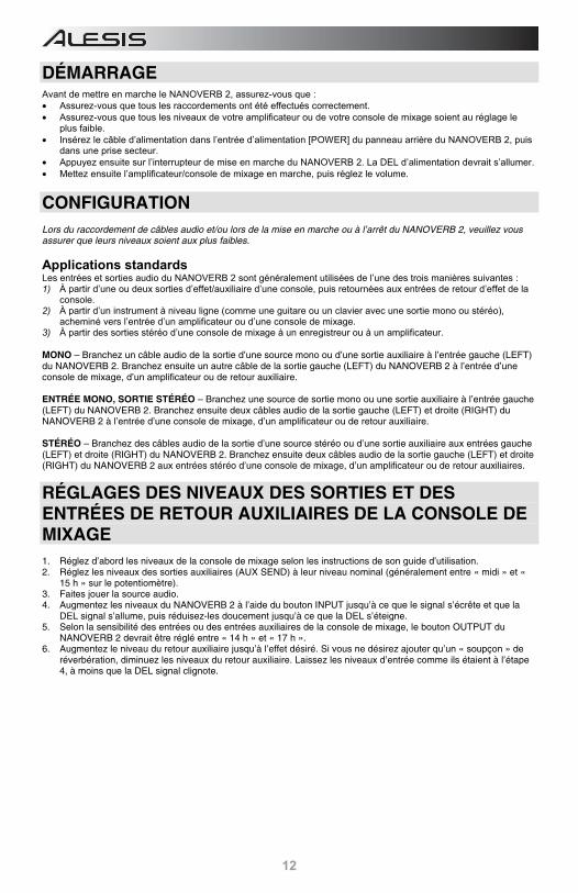
DÉMARRAGE Avant de mettre en marche le NANOVERB 2, assurez-vous que : • Assurez-vous que tous les raccordements ont été effectués correctement. • Assurez-vous que tous les niveaux de votre amplificateur ou de votre console de mixage soient au réglage le
plus faible. • Insérez le câble d’alimentation dans l’entrée d’alimentation [POWER] du panneau arrière du NANOVERB 2, puis
dans une prise secteur. • Appuyez ensuite sur l’interrupteur de mise en marche du NANOVERB 2. La DEL d’alimentation devrait s’allumer. • Mettez ensuite l’amplificateur/console de mixage en marche, puis réglez le volume.
CONFIGURATION Lors du raccordement de câbles audio et/ou lors de la mise en marche ou à l’arrêt du NANOVERB 2, veuillez vous assurer que leurs niveaux soient aux plus faibles.
Applications standards Les entrées et sorties audio du NANOVERB 2 sont généralement utilisées de l’une des trois manières suivantes : 1) À partir d’une ou deux sorties d’effet/auxiliaire d’une console, puis retournées aux entrées de retour d’effet de la
console. 2) À partir d’un instrument à niveau ligne (comme une guitare ou un clavier avec une sortie mono ou stéréo),
acheminé vers l’entrée d’un amplificateur ou d’une console de mixage. 3) À partir des sorties stéréo d’une console de mixage à un enregistreur ou à un amplificateur. MONO – Branchez un câble audio de la sortie d’une source mono ou d’une sortie auxiliaire à l’entrée gauche (LEFT) du NANOVERB 2. Branchez ensuite un autre câble de la sortie gauche (LEFT) du NANOVERB 2 à l’entrée d’une console de mixage, d’un amplificateur ou de retour auxiliaire. ENTRÉE MONO, SORTIE STÉRÉO – Branchez une source de sortie mono ou une sortie auxiliaire à l’entrée gauche (LEFT) du NANOVERB 2. Branchez ensuite deux câbles audio de la sortie gauche (LEFT) et droite (RIGHT) du NANOVERB 2 à l’entrée d’une console de mixage, d’un amplificateur ou de retour auxiliaire. STÉRÉO – Branchez des câbles audio de la sortie d’une source stéréo ou d’une sortie auxiliaire aux entrées gauche (LEFT) et droite (RIGHT) du NANOVERB 2. Branchez ensuite deux câbles audio de la sortie gauche (LEFT) et droite (RIGHT) du NANOVERB 2 aux entrées stéréo d’une console de mixage, d’un amplificateur ou de retour auxiliaires.
RÉGLAGES DES NIVEAUX DES SORTIES ET DES ENTRÉES DE RETOUR AUXILIAIRES DE LA CONSOLE DE MIXAGE 1. Réglez d’abord les niveaux de la console de mixage selon les instructions de son guide d’utilisation. 2. Réglez les niveaux des sorties auxiliaires (AUX SEND) à leur niveau nominal (généralement entre « midi » et «
15 h » sur le potentiomètre). 3. Faites jouer la source audio. 4. Augmentez les niveaux du NANOVERB 2 à l’aide du bouton INPUT jusqu’à ce que le signal s’écrête et que la
DEL signal s’allume, puis réduisez-les doucement jusqu’à ce que la DEL s’éteigne. 5. Selon la sensibilité des entrées ou des entrées auxiliaires de la console de mixage, le bouton OUTPUT du
NANOVERB 2 devrait être réglé entre « 14 h » et « 17 h ». 6. Augmentez le niveau du retour auxiliaire jusqu’à l’effet désiré. Si vous ne désirez ajouter qu’un « soupçon » de
réverbération, diminuez les niveaux du retour auxiliaire. Laissez les niveaux d’entrée comme ils étaient à l’étape 4, à moins que la DEL signal clignote.
13
EFFETS
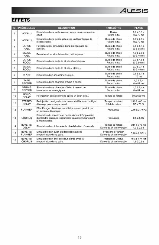
N˚ PRÉRÉGLAGE DESCRIPTION PARAMÈTRE PLAGE
1 VOCAL 1 Simulation d’une salle avec un temps de réverbération court.
DuréeRetard initial
0,8 à 1,1 s 0 à 79 ms
2 VOCAL 2 Simulation d’une petite salle avec un léger temps de réverbération.
Durée de chuteRetard initial
0,8 à 2,5 s 0 à 79 ms
3 LARGE HALL
Réverbération, simulation d’une grande salle de concert.
Durée de chuteRetard initial
3,6 à 5,4 s 23 à 55 ms
4 SMALL HALL
Réverbération, simulation d’un petit espace. Durée de chute
Retard initial 1,0 à 2,9 s 20 à 45 ms
5 LARGE ROOM Simulation d’une salle de studio réverbérante.
Durée de chuteRetard initial
2,9 à 4,5 s 23 à 55 ms
6 SMALL ROOM Simulation d’une salle de studio « claire ».
Durée de chuteRetard initial
0,7 à 2,1 s 20 à 45 ms
7 PLATE Simulation d’un son clair classique. Durée de chuteRetard initial
0,6 à 6,1 s 10 ms
8 TAPE
REVERB Simulation d’une chambre d’écho à bande.
Durée de chuteRetard initial
1,3 à 5,4 0 à 84 ms
9 SPRING REVERB
Simulation d’une chambre d’écho à ressort de transducteurs analogiques.
Durée de chuteRetard initial
1,3 à 5,4 s 0 à 84 ms
10 MONO DELAY
Ré-injection du signal mono après un court délai. Temps de retard 60 à 650 ms
11 STEREO DELAY
Ré-injection du signal après un court délai avec un léger décalage pour chaque canal.
Temps de retardEffet de retour
210 à 400 ms 37 à 73 %
12 FLANGER Effet Flanger classique, semblable au son produit par un avion au décollage.
Fréquence 0,16 à 2,79 Hz
13 CHORUS Simulation du son riche et dense donnant l’impression d’entendre plusieurs instruments jouant simultanément la même partie.
Fréquence 0,5 à 5 Hz
14 REVERB+
DELAY Simulation d’un écho avec la réverbération d’une salle.
Temps de retardDurée de chute inversée
211 à 375 ms 1,0 à 2,9 s
15 REVERB+ FLANGER
Simulation d’un avion au décollage avec la réverbération d’une salle.
Fréquence FlangerDurée de chute inversée
0,16 à 2,52 Hz
16 REVERB+ CHORUS
Simulation d’un effet de cœur stéréo avec la réverbération d’une salle.
Fréquence ChorusDurée de chute inversée
0,5 à 4,74 Hz 1,5 à 2,9 s
14
GUIDE DE DÉPANNAGE
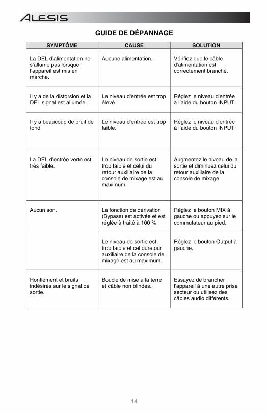
SYMPTÔME CAUSE SOLUTION La DEL d’alimentation ne s’allume pas lorsque l’appareil est mis en marche.
Aucune alimentation.
Vérifiez que le câble d’alimentation est correctement branché.
Il y a de la distorsion et la DEL signal est allumée.
Le niveau d'entrée est trop élevé
Réglez le niveau d'entrée à l’aide du bouton INPUT.
Il y a beaucoup de bruit de fond
Le niveau d'entrée est trop faible.
Réglez le niveau d'entrée à l’aide du bouton INPUT.
La DEL d’entrée verte est très faible.
Le niveau de sortie est trop faible et celui du retour auxiliaire de la console de mixage est au maximum.
Augmentez le niveau de la sortie et diminuez celui du retour auxiliaire de la console de mixage.
Aucun son.
La fonction de dérivation (Bypass) est activée et est réglée à traité à 100 %
Réglez le bouton MIX à gauche ou appuyez sur le commutateur au pied.
Le niveau de sortie est trop faible et cel duretour auxiliaire de la console de mixage est au maximum.
Réglez le bouton Output à gauche.
Ronflement et bruits indésirés sur le signal de sortie.
Boucle de mise à la terre et câble non blindés.
Essayez de brancher l’appareil à une autre prise secteur ou utilisez des câbles audio différents.
15
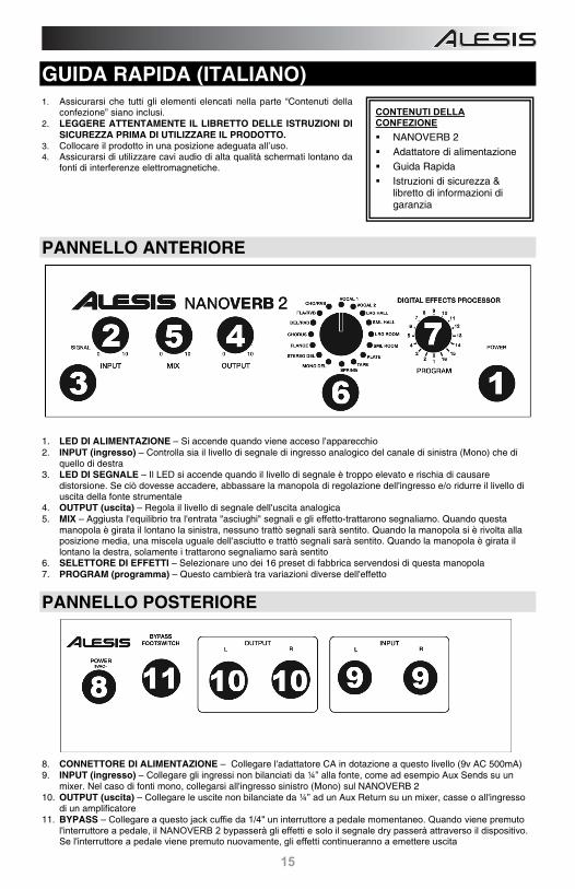
GUIDA RAPIDA (ITALIANO) 1. Assicurarsi che tutti gli elementi elencati nella parte “Contenuti della
confezione” siano inclusi. 2. LEGGERE ATTENTAMENTE IL LIBRETTO DELLE ISTRUZIONI DI
SICUREZZA PRIMA DI UTILIZZARE IL PRODOTTO. 3. Collocare il prodotto in una posizione adeguata all’uso. 4. Assicurarsi di utilizzare cavi audio di alta qualità schermati lontano da
fonti di interferenze elettromagnetiche.
PANNELLO ANTERIORE
1. LED DI ALIMENTAZIONE – Si accende quando viene acceso l'apparecchio 2. INPUT (ingresso) – Controlla sia il livello di segnale di ingresso analogico del canale di sinistra (Mono) che di
quello di destra 3. LED DI SEGNALE – Il LED si accende quando il livello di segnale è troppo elevato e rischia di causare
distorsione. Se ciò dovesse accadere, abbassare la manopola di regolazione dell'ingresso e/o ridurre il livello di uscita della fonte strumentale
4. OUTPUT (uscita) – Regola il livello di segnale dell'uscita analogica 5. MIX – Aggiusta l'equilibrio tra l'entrata "asciughi" segnali e gli effetto-trattarono segnaliamo. Quando questa
manopola è girata il lontano la sinistra, nessuno trattò segnali sarà sentito. Quando la manopola si è rivolta alla posizione media, una miscela uguale dell'asciutto e trattò segnali sarà sentito. Quando la manopola è girata il lontano la destra, solamente i trattarono segnaliamo sarà sentito
6. SELETTORE DI EFFETTI – Selezionare uno dei 16 preset di fabbrica servendosi di questa manopola 7. PROGRAM (programma) – Questo cambierà tra variazioni diverse dell'effetto
PANNELLO POSTERIORE
8. CONNETTORE DI ALIMENTAZIONE – Collegare l'adattatore CA in dotazione a questo livello (9v AC 500mA) 9. INPUT (ingresso) – Collegare gli ingressi non bilanciati da ¼” alla fonte, come ad esempio Aux Sends su un
mixer. Nel caso di fonti mono, collegarsi all'ingresso sinistro (Mono) sul NANOVERB 2 10. OUTPUT (uscita) – Collegare le uscite non bilanciate da ¼” ad un Aux Return su un mixer, casse o all'ingresso
di un amplificatore 11. BYPASS – Collegare a questo jack cuffie da 1/4" un interruttore a pedale momentaneo. Quando viene premuto
l'interruttore a pedale, il NANOVERB 2 bypasserà gli effetti e solo il segnale dry passerà attraverso il dispositivo. Se l'interruttore a pedale viene premuto nuovamente, gli effetti continueranno a emettere uscita
CONTENUTI DELLA CONFEZIONE NANOVERB 2 Adattatore di alimentazione Guida Rapida Istruzioni di sicurezza &
libretto di informazioni di garanzia
16
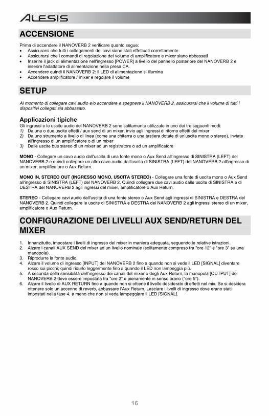
ACCENSIONE Prima di accendere il NANOVERB 2 verificare quanto segue: • Assicurarsi che tutti i collegamenti dei cavi siano stati effettuati correttamente • Assicurarsi che i comandi di regolazione del volume di amplificatore e mixer siano abbassati • Inserire il jack di alimentazione nell'ingresso [POWER] a livello del pannello posteriore del NANOVERB 2 e
inserire l'adattatore di alimentazione nella presa CA. • Accendere quindi il NANOVERB 2: il LED di alimentazione si illumina • Accendere amplificatore / mixer e regolare il volume
SETUP Al momento di collegare cavi audio e/o accendere e spegnere il NANOVERB 2, assicurarsi che il volume di tutti i dispositivi collegati sia abbassato.
Applicazioni tipiche Gli ingressi e le uscite audio del NANOVERB 2 sono solitamente utilizzate in uno dei tre seguenti modi: 1) Da una o due uscite effetti / aux send di un mixer, invio agli ingressi di ritorno effetti del mixer 2) Da uno strumento a livello di linea (come una chitarra o una tastiera dotate di un'uscita mono o stereo), inviate
all'ingresso di un amplificatore o di un mixer 3) Dalle uscite bus stereo di un mixer ad un registratore o ad un amplificatore MONO - Collegare un cavo audio dall'uscita di una fonte mono o Aux Send all'ingresso di SINISTRA (LEFT) del NANOVERB 2 e quindi collegare un altro cavo audio dall'uscita di SINISTRA (LEFT) del NANOVERB 2 all'ingresso di un mixer, amplificatore o Aux Return. MONO IN, STEREO OUT (INGRESSO MONO, USCITA STEREO) - Collegare una fonte di uscita mono o Aux Send all'ingresso di SINISTRA (LEFT) del NANOVERB 2. Quindi collegare due cavi audio dalle uscite di SINISTRA e di DESTRA del NANOVERB 2 agli ingressi del mixer, amplificatore o Aux Return. STEREO - Collegare cavi audio dall'uscita di una fonte stereo o Aux Send agli ingressi di SINISTRA e DESTRA del NANOVERB 2. Quindi collegare le uscite di SINISTRA e DESTRA del NANOVERB 2 agli ingressi stereo di un mixer, amplificatore o Aux Return.
CONFIGURAZIONE DEI LIVELLI AUX SEND/RETURN DEL MIXER 1. Innanzitutto, impostare i livelli di ingresso del mixer in maniera adeguata, seguendo le relative istruzioni. 2. Alzare i canali AUX SEND del mixer ad un livello nominale (solitamente compreso tra "ore 12" e "ore 3" su una
manopola). 3. Riprodurre la fonte audio. 4. Alzare il volume di ingresso [INPUT] del NANOVERB 2 fino a quando non si vede il LED [SIGNAL] diventare
rosso sui picchi; quindi ridurlo leggermente fino a quando il LED non lampeggia più. 5. A seconda della sensibilità dell'ingresso dei canali del mixer o degli Aux Return, la manopola [OUTPUT] del
NANOVERB 2 deve essere impostata tra "ore 2" e pienamente in senso orario ("ore 5"). 6. Alzare il livello di AUX RETURN fino a quando non si ottiene il livello desiderato di effetti nel mix. Se si desidera
ottenere solo un accenno di reverb, abbassare l'Aux Return. Lasciare i livelli di ingresso dove erano stati impostati nella fase 4, a meno che non si veda lampeggiare il LED [SIGNAL].
17
EFFETTI
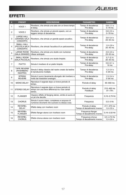
# PRESET DESCRIZIONE PARAMETRO GAMMA
1 VOCE 1 Riverbero, che simula una sala con un breve tempo di delay.
Tempo di decadenzaPre-delay
0,8~1,1 s 0~79 ms
2 VOCE 2 Riverbero, che simula un piccolo spazio, con un leggero tempo di decadenza.
Tempo di decadenzaPre-delay
0,8~2,5 s 0~79 ms
3 LARGE HALL
(GRANDE SALA CONCERTI)
Riverbero, che simula un grande spazio acustico. Tempo di decadenza
Pre-delay 3,6~5,4 s 23~55 ms
4 SMALL HALL
(PICCOLA SALA CONCERTI)
Riverbero, che simula l'acustica di un palcoscenico.Tempo di decadenza
Pre-delay 1,0~2,9 s 20~45 ms
5 LARGE ROOM
(SALA GRANDE) Riverbero, che simula uno studio con numerosi riflessi anticipati.
Tempo di decadenzaPre-delay
2,9~4,5 s 23~55 ms
6 SMALL ROOM
(SALA PICCOLA) Riverbero, che simula uno studio limpido.
Tempo di decadenzaPre-delay
0,7~2,1s 20~45 ms
7 PIATTO Simula il riverbero di un piatto limpido. Tempo di decadenza
Pre-delay0,6~6,1 s
10 ms
8 TAPE REVERB (RIVERBERO
NASTRO)
Simula il delay classico del nastro creato da testine di riproduzione multiple.
Tempo di decadenza Pre-delay
1,3~5,4 s 0~84 ms
9 SPRING REVERB
Simula il suono lievemente allungato del riverbero a molla dai trasduttori analogici.
Tempo di decadenzaPre-delay
1,3~5,4 s 0~84 ms
10 MONO DELAY Riproduce il segnale dopo un breve periodo di tempo.
Periodo di delay 60~650 ms
11 STEREO DELAY Riproduce il segnale dopo un breve periodo di tempo con una lieve differenza tra i due canali stereo.
Periodo di delay Feedback
210~400 ms 37~73%
12 FLANGER Classico effetto di flanging stereo, simile al suono di un jet che decolla.
Frequenza 0,16~2,79 Hz
13 CHORUS Simula il suono intero, complesso e acquoso di numerosi strumenti che suonano la stessa cosa.
Frequenza 0,5~5 Hz
14 REVERB+
DELAY Effetto delay con riverbero room
Periodo di delayTempo di decadimento inverso
211~375 ms 1,0~2,9 s
15 REVERB+ FLANGER
Effetto flanger stereo con riverbero room Frequenza flanger
Tempo di decadimento inverso0,16~2,52 Hz
16 REVERB+ CHORUS Effetto chorus stereo con riverbero room
Frequenza chorusTempo di decadimento inverso
0,5~4,74 Hz 1,5~2,9 s
18
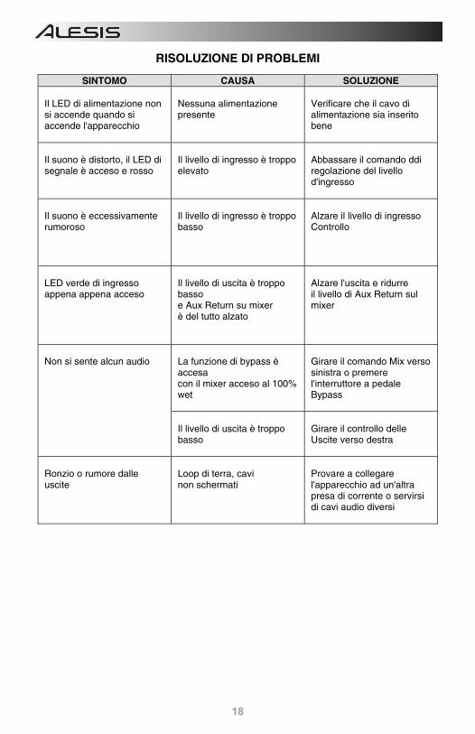
RISOLUZIONE DI PROBLEMI
SINTOMO CAUSA SOLUZIONE Il LED di alimentazione non si accende quando si accende l'apparecchio
Nessuna alimentazione presente
Verificare che il cavo di alimentazione sia inserito bene
Il suono è distorto, il LED di segnale è acceso e rosso
Il livello di ingresso è troppo elevato
Abbassare il comando ddi regolazione del livello d'ingresso
Il suono è eccessivamente rumoroso
Il livello di ingresso è troppo basso
Alzare il livello di ingresso Controllo
LED verde di ingresso appena appena acceso
Il livello di uscita è troppo basso e Aux Return su mixer è del tutto alzato
Alzare l'uscita e ridurre il livello di Aux Return sul mixer
Non si sente alcun audio
La funzione di bypass è accesa con il mixer acceso al 100% wet
Girare il comando Mix verso sinistra o premere l'interruttore a pedale Bypass
Il livello di uscita è troppo basso
Girare il controllo delle Uscite verso destra
Ronzio o rumore dalle uscite
Loop di terra, cavi non schermati
Provare a collegare l'apparecchio ad un'altra presa di corrente o servirsi di cavi audio diversi
19
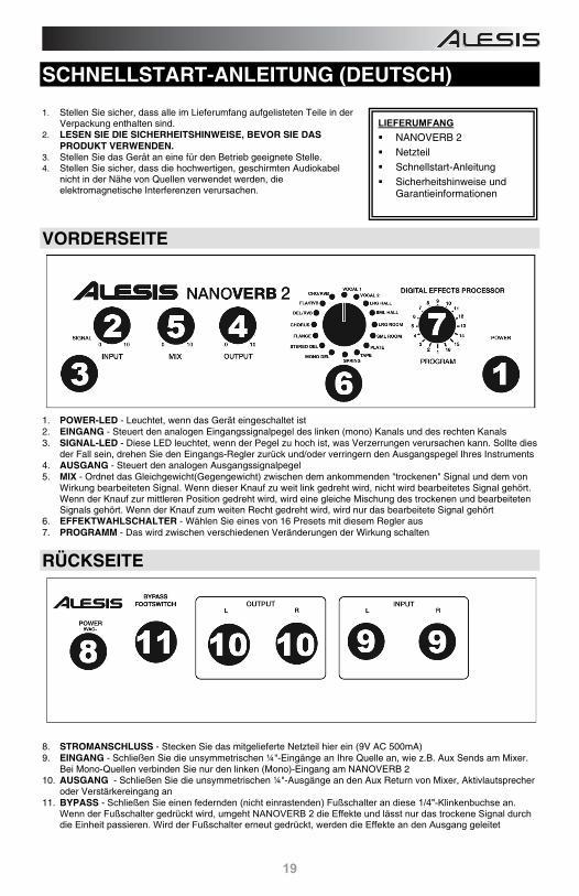
SCHNELLSTART-ANLEITUNG (DEUTSCH) 1. Stellen Sie sicher, dass alle im Lieferumfang aufgelisteten Teile in der
Verpackung enthalten sind. 2. LESEN SIE DIE SICHERHEITSHINWEISE, BEVOR SIE DAS
PRODUKT VERWENDEN. 3. Stellen Sie das Gerät an eine für den Betrieb geeignete Stelle. 4. Stellen Sie sicher, dass die hochwertigen, geschirmten Audiokabel
nicht in der Nähe von Quellen verwendet werden, die elektromagnetische Interferenzen verursachen.
VORDERSEITE
1. POWER-LED - Leuchtet, wenn das Gerät eingeschaltet ist 2. EINGANG - Steuert den analogen Eingangssignalpegel des linken (mono) Kanals und des rechten Kanals 3. SIGNAL-LED - Diese LED leuchtet, wenn der Pegel zu hoch ist, was Verzerrungen verursachen kann. Sollte dies
der Fall sein, drehen Sie den Eingangs-Regler zurück und/oder verringern den Ausgangspegel Ihres Instruments 4. AUSGANG - Steuert den analogen Ausgangssignalpegel 5. MIX - Ordnet das Gleichgewicht(Gegengewicht) zwischen dem ankommenden "trockenen" Signal und dem von
Wirkung bearbeiteten Signal. Wenn dieser Knauf zu weit link gedreht wird, nicht wird bearbeitetes Signal gehört. Wenn der Knauf zur mittleren Position gedreht wird, wird eine gleiche Mischung des trockenen und bearbeiteten Signals gehört. Wenn der Knauf zum weiten Recht gedreht wird, wird nur das bearbeitete Signal gehört
6. EFFEKTWAHLSCHALTER - Wählen Sie eines von 16 Presets mit diesem Regler aus 7. PROGRAMM - Das wird zwischen verschiedenen Veränderungen der Wirkung schalten
RÜCKSEITE
8. STROMANSCHLUSS - Stecken Sie das mitgelieferte Netzteil hier ein (9V AC 500mA) 9. EINGANG - Schließen Sie die unsymmetrischen ¼"-Eingänge an Ihre Quelle an, wie z.B. Aux Sends am Mixer.
Bei Mono-Quellen verbinden Sie nur den linken (Mono)-Eingang am NANOVERB 2 10. AUSGANG - Schließen Sie die unsymmetrischen ¼"-Ausgänge an den Aux Return von Mixer, Aktivlautsprecher
oder Verstärkereingang an 11. BYPASS - Schließen Sie einen federnden (nicht einrastenden) Fußschalter an diese 1/4"-Klinkenbuchse an.
Wenn der Fußschalter gedrückt wird, umgeht NANOVERB 2 die Effekte und lässt nur das trockene Signal durch die Einheit passieren. Wird der Fußschalter erneut gedrückt, werden die Effekte an den Ausgang geleitet
LIEFERUMFANG NANOVERB 2 Netzteil Schnellstart-Anleitung Sicherheitshinweise und
Garantieinformationen
20
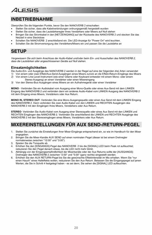
INBETRIEBNAHME Überprüfen Sie die folgenden Punkte, bevor Sie den NANOVERB 2 einschalten: • Stellen Sie sicher, dass alle Kabelverbindungen ordnungsgemäß hergestellt wurden • Stellen Sie sicher, dass die Lautstärkeregler Ihres Verstärkers oder Mixers auf Null stehen • Bringen Sie das Stromkabel in den [NETZEINGANG] auf der Rückseite des NANOVERB 2 und stecken Sie das
Netzteil in eine Steckdose • Schalten Sie NANOVERB 2 anschließend ein. Die LED-Anzeige für "Power On" wird leuchten. • Schalten Sie die Stromversorgung des Verstärkers/Mixers ein und passen Sie die Lautstärke an
SETUP Vergewissern Sie sich beim Anschluss der Audio-Kabel und/oder beim Ein- und Ausschalten des NANOVERB 2, dass die Lautstärken aller angeschlossenen Geräte auf Null stehen.
Einsatzmöglichkeiten Die Audio-Ein- und Ausgänge des NANOVERB 2 werden in der Regel auf eine der folgenden drei Arten verwendet: 1) Von einem oder zwei Effekt/Aux-Send-Ausgängen eines Mixers zurück an die Effekt-Return-Eingänge des Mixers 2) Von einem Line-Level-Instrument (wie einer Gitarre oder Keyboard entweder mit einem Mono- oder einem
Stereo-Ausgang) an einen Verstärker oder einen Mixereingang 3) Von den Stereo-Bus-Ausgängen eines Mixers an ein Aufnahmegerät oder einen Verstärker MONO - Verbinden Sie ein Audiokabel vom Ausgang einer Mono-Quelle oder eines Aux-Send mit dem LINKEN Eingang des NANOVERB 2 und verbinden dann ein anderes Audio-Kabel vom LINKEN Ausgang des NANOVERB 2 mit dem Eingang eines Mixers, Verstärkers oder Aux Return. MONO IN, STEREO OUT- Verbinden Sie eine Mono-Ausgangsquelle oder einen Aux Send mit dem LINKEN Eingang des NANOVERB 2. Dann verbinden Sie zwei Audio-Kabel von den LINKEN und RECHTEN Ausgängen des NANOVERB 2 mit den Eingängen Ihres Mixers, Verstärkers oder Aux Return. STEREO- Verbinden Sie Audio-Kabel vom Ausgang einer Stereoquelle oder eines Aux Send mit den LINKEN und RECHTEN Eingängen des NANOVERB 2. Verbinden Sie anschließend die LINKEN und RECHTEN Ausgänge des NANOVERB 2 mit den Stereoeingängen eines Mixers, Verstärkers oder Aux Return.
MIXEREINSTELLUNGEN FÜR AUX SEND-/RETURN-PEGEL 1. Stellen Sie zunächst die Einstellungen Ihrer Mixer-Eingänge entsprechend ein, so wie im Handbuch für den Mixer
angegeben. 2. Bringen Sie die Mixer-Kanäle AUX SEND auf einen nominalen Pegel (dieser ist bei einem Drehregler
normalerweise zwischen "12:00" und "3:00"). 3. Spielen Sie die Tonquelle ab. 4. Erhöhen Sie den [EINGANGS]-Pegel des NANOVERB 2 bis die [SIGNAL]-LED beim Peak rot aufleuchtet;
reduzieren Sie den Pegel danach etwas, bis die LED nicht mehr blinkt. 5. Abhängig von der Eingangsempfindlichkeit der Mixerkanäle oder der Aux Returns sollte der [AUSGANGS]-
Drehregler des NANOVERB 2 zwischen "2:00" und "5:00" (ganz rechts) eingestellt werden. 6. Erhöhen Sie den AUX RETURN-Pegel bis Sie die gewünschte Effektintensität im Mix erhalten. Wenn Sie "nur
einen Hauch" eines Halleffekts wollen, reduzieren Sie den Aux Return. Belassen Sie die Eingangspegel auf jenen Werten, die Sie in Schritt 4 festgelegt haben - es sei denn, Sie sehen die [SIGNAL] LED aufleuchten.
21
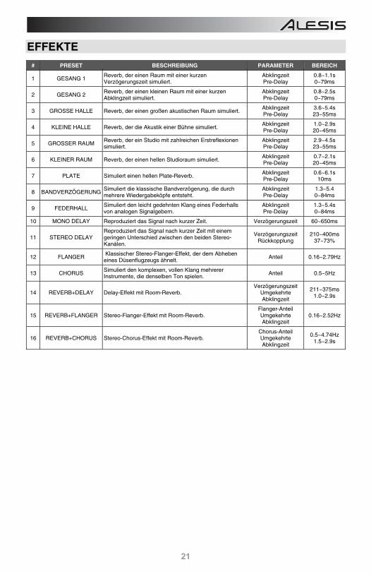
EFFEKTE
# PRESET BESCHREIBUNG PARAMETER BEREICH
1 GESANG 1 Reverb, der einen Raum mit einer kurzen Verzögerungszeit simuliert.
AbklingzeitPre-Delay
0.8~1.1s 0~79ms
2 GESANG 2 Reverb, der einen kleinen Raum mit einer kurzen Abklingzeit simuliert.
AbklingzeitPre-Delay
0.8~2.5s 0~79ms
3 GROSSE HALLE Reverb, der einen großen akustischen Raum simuliert. AbklingzeitPre-Delay
3.6~5.4s 23~55ms
4 KLEINE HALLE Reverb, der die Akustik einer Bühne simuliert. AbklingzeitPre-Delay
1.0~2.9s 20~45ms
5 GROSSER RAUM Reverb, der ein Studio mit zahlreichen Erstreflexionen simuliert.
AbklingzeitPre-Delay
2.9~4.5s 23~55ms
6 KLEINER RAUM Reverb, der einen hellen Studioraum simuliert. AbklingzeitPre-Delay
0.7~2.1s 20~45ms
7 PLATE Simuliert einen hellen Plate-Reverb. AbklingzeitPre-Delay
0.6~6.1s 10ms
8 BANDVERZÖGERUNGSimuliert die klassische Bandverzögerung, die durch mehrere Wiedergabeköpfe entsteht.
AbklingzeitPre-Delay
1.3~5.4 0~84ms
9 FEDERHALL Simuliert den leicht gedehnten Klang eines Federhalls von analogen Signalgebern.
AbklingzeitPre-Delay
1.3~5.4s 0~84ms
10 MONO DELAY Reproduziert das Signal nach kurzer Zeit. Verzögerungszeit 60~650ms
11 STEREO DELAY Reproduziert das Signal nach kurzer Zeit mit einem geringen Unterschied zwischen den beiden Stereo-Kanälen.
Verzögerungszeit Rückkopplung
210~400ms 37~73%
12 FLANGER Klassischer Stereo-Flanger-Effekt, der dem Abheben
eines Düsenflugzeugs ähnelt. Anteil 0.16~2.79Hz
13 CHORUS Simuliert den komplexen, vollen Klang mehrerer Instrumente, die denselben Ton spielen. Anteil 0.5~5Hz
14 REVERB+DELAY Delay-Effekt mit Room-Reverb. Verzögerungszeit
Umgekehrte Abklingzeit
211~375ms 1.0~2.9s
15 REVERB+FLANGER Stereo-Flanger-Effekt mit Room-Reverb. Flanger-AnteilUmgekehrte Abklingzeit
0.16~2.52Hz
16 REVERB+CHORUS Stereo-Chorus-Effekt mit Room-Reverb. Chorus-AnteilUmgekehrte Abklingzeit
0.5~4.74Hz 1.5~2.9s
22
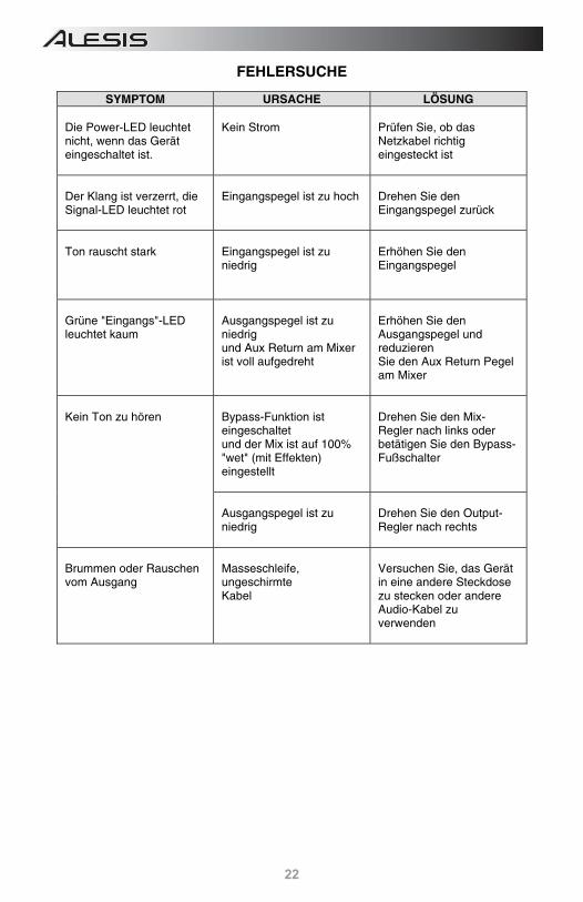
FEHLERSUCHE
SYMPTOM URSACHE LÖSUNG Die Power-LED leuchtet nicht, wenn das Gerät eingeschaltet ist.
Kein Strom
Prüfen Sie, ob das Netzkabel richtig eingesteckt ist
Der Klang ist verzerrt, die Signal-LED leuchtet rot
Eingangspegel ist zu hoch
Drehen Sie den Eingangspegel zurück
Ton rauscht stark
Eingangspegel ist zu niedrig
Erhöhen Sie den Eingangspegel
Grüne "Eingangs"-LED leuchtet kaum
Ausgangspegel ist zu niedrig und Aux Return am Mixer ist voll aufgedreht
Erhöhen Sie den Ausgangspegel und reduzieren Sie den Aux Return Pegel am Mixer
Kein Ton zu hören
Bypass-Funktion ist eingeschaltet und der Mix ist auf 100% "wet" (mit Effekten) eingestellt
Drehen Sie den Mix-Regler nach links oder betätigen Sie den Bypass-Fußschalter
Ausgangspegel ist zu niedrig
Drehen Sie den Output-Regler nach rechts
Brummen oder Rauschen vom Ausgang
Masseschleife, ungeschirmte Kabel
Versuchen Sie, das Gerät in eine andere Steckdose zu stecken oder andere Audio-Kabel zu verwenden
23
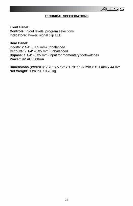
TECHNICAL SPECIFICATIONS Front Panel: Controls: In/out levels, program selections Indicators: Power, signal clip LED Rear Panel: Inputs: 2 1/4" (6.35 mm) unbalanced Outputs: 2 1/4" (6.35 mm) unbalanced Bypass: 1 1/4" (6.35 mm) input for momentary footswitches Power: 9V AC, 500mA Dimensions (WxDxH): 7.76" x 5.12" x 1.73" / 197 mm x 131 mm x 44 mm Net Weight: 1.26 lbs. / 0.76 kg

alesis.com
7-51-0357-D


![1BDJGJD +PVSOBM PG .BUIFNBUJDT · Troughout this paper the word "group" will mean "abelian group". The notation of [2] will be followed. The letter p will indicate a prime. The elements](https://img.pdfslide.tips/doc/110x75/60d862341ba5b55dfb411ec4/1bdjgjd-pvsobm-pg-buifnbujdt-troughout-this-paper-the-word-group-will.jpg)