Embed Size (px)
Citation preview

5/14/2018 Neutral Gr Reactor - slidepdf.com
http://slidepdf.com/reader/full/neutral-gr-reactor 1/6
Optimisation of Neutral Grounding Reactor Parameters - an Analysis foDouble Circuit EHV Line
学术搜索
Nayak, R.N.; Sehgal, Y.K.; Subir Sen; Gupta, M.Power India Conference, 2006 IEEE544-548April 10-12, 2006学术搜索
www.libsou.com
scholar search
5/14/2018 Neutral Gr Reactor - slidepdf.com
http://slidepdf.com/reader/full/neutral-gr-reactor 2/6
0
20
40
60
80
100
120
0 100 200 300 400 500
Line Length (in km)
SecondaryCurrent(A)
0
25
50
75
100
125
RecoveryVoltage(kV)
Optimization of Neutral Grounding Reactor Parameters - An Analysis for a Double circuit
EHV LineR. N. Nayak, Senior Member, IEEE , Y. K. Sehgal, Subir Sen, and Manju Gupta
Abstract-- In order to maintain power transmission reliability,
application of Single-phase switching (SPS) and auto-reclosing on
EHV line is a common practice. However, in some cases, it is
necessary to apply special means like Neutral Grounding Reactor
(NGR) to improve the conditions for secondary arc extinction for
successful auto-reclosing. This paper presents importance of
various parameters in optimization of NGR in a double circuit
(D/c) EHV line. In case of SPS on D/c line, the secondary arc is
maintained not only by the inter-phase coupling of the faulted
circuit but also by the mutual coupling of the other healthy
circuit. An empirical formula for NGR value of a double circuit
line along with the methodology for its optimization is presented.Magnitude of secondary arc current also depends on the line
length, power flow, source strength etc. Sensitivity of various
parameters on Secondary arc current has been demonstrated
through EMTP study.
Index Terms-- EMTP, Neutral Grounding Reactor, Recovery
voltage, Secondary arc current, Single Pole Switching
I. I NTRODUCTION
INGLE-phase-to-ground faults account for 70% - 95% of faults on EHV transmission lines and most of these are
transitory in nature. From the stand point of minimizing the
disturbances, especially loss of synchronism thus hamperingsystem stability, caused by such faults, as well as to maintainreliability, it is desirable to clear them by opening only thecircuit-breaker pole on both terminals of the faulted phase outof the three phases and then reclose after certain time gap.This allows two energized and healthy phases to continuecarrying power during the period of interruption, which hassignificant benefits [1]. The increasing difficulty of construction of new EHV transmission lines as well as highcost makes Single Phase Switching (SPS) attractive means of obtaining reliable power delivery system. SPS, also incomparison with three phase reclosing, has the additional
benefit of reducing the torsional impact on turbine-generator
shaft.During the dead time of SPS, extinction of the maintransient arc current should take place. However, the faulted
phase remains capacitively and inductively coupled with theenergized unfaulted phases resulting in a continuat5ion of thefault (arc), current, which is known as secondary arc current[2]. If single-phase switching is adopted, care must be taken
R.N.Nayak, Y.K.Sehgal, Subir Sen and Manju Gupta are with Power GridCorporation of India Ltd, Sector-29, Gurgaon(Haryana), India (Ph: 0124-2571815; Fax: 0124-2571802; E-mail: [email protected]
0-7803-9525-5/06/$20.00©2006 IEEE
that the ionized faulted path is de-ionized in time so tdielectric strength is re-built and secondary arc curren
promptly extinguished to facilitate successful reclosurecase of SPS on double circuit (D/c) EHV line, the secondarc is maintained not only by the inter-phase capacitcoupling between faulted phase and energized phases of same circuit, but also by the mutual coupling of the othealthy circuit. Use of Neutral Grounding Reactor (NGRthe neutral point of the shunt reactor on long EHV linewidely adopted to ensure successful SPS. In case of sincircuit(S/c) line, based on the given reactor size, ohmic vaof the neutral reactor necessary to compensate the inter-phcapacitance is calculated. However, very little research
been done for treatment of double circuit line.In this paper, an empirical formula for determination
NGR value for a double circuit EHV line has been establis
as an extension of single circuit line and validated throu
EMTP simulation. Methodology for optimization of N
parameters like size (ohmic value), current rating etc
presented with a sample case study. Further, impact on
size of NGR value with variation in line length, sou
strength, power flow etc. for successful SPS of double cir
line have been examined through EMTP studies and res
are discussed in the paper.
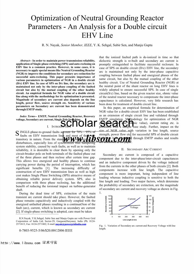
II. SECONDARY ARC CURRENT
Secondary arc current is composed of a capaci
component due to the inter-phase/inter-circuit capacitan
and an inductive component driven by the voltage indu
from the currents in the other phases of both circuits [2]. B
components increase with line length. The capacit
component is more important, being independent of
loading whereas inductive coupling is sensitive to both
line length and loading. Two major factors, which determ
the probability of secondary arc extinction, are the magnit
of secondary arc current and recovery voltage as shown in F
1.
Fig. 1. Variation of Secondary arc current and Recovery Voltage with linlength.
S
Current
Voltage
htt : www.libsou.com
www.libsou.com
scholar search
5/14/2018 Neutral Gr Reactor - slidepdf.com
http://slidepdf.com/reader/full/neutral-gr-reactor 3/6
htt : www.libsou.com
Various methods have been suggested for reducing thesecondary arc current. For successful SPS, it is desirable tohave arc extinction during the dead time for majority of thetime. Reclosing time is often set in the range of 0.5-1 seconds.Extinction time is also dependent on atmospheric conditionsand arc length. For long EHV lines, two methods are beingconsidered to minimize the secondary arc current to ensuresuccessful SPS mechanism. Out of these, four reactor schemehad a great deal of appeal for this application since phase/linereactors are required for long EHV line to control voltage. The
fourth reactor of suitable size connected at the neutral point of the three phase reactors and ground (known as NeutralGrounding Reactor), cancels the inter-phase/inter-circuitcapacitances between faulted and unfaulted phases, thus,facilitates reduction of magnitude of secondary arc current andrecovery voltage. If an optimum reactive compensationscheme is used, secondary arc current would be of lowmagnitude (driven only by the inductive coupling) and in mostof the cases, arc would be expected to extinguish within ashort dead time.
III. NGR VALUE TO COMPENSATE CAPACITIVE COUPLING
A typical double circuit line with intra and inter-phasecapacitive coupling along with shunt inductive compensationis represented in Fig. 2
Cm
Cm
CKT 2
CKT 1
Cm
C1b
c
a
c
b
a
Fig. 2. Intra and Inter-phase Capacitive Coupling.
Where,C1 : positive sequence phase capacitance of lineC0 : zero sequence capacitance of lineCm : mutual capacitance between phasesL1 : positive sequence inductance of shunt reactor L0 : zero sequence inductance of shunt reactor Ln : neutral grounding reactor inductance
The neutral grounding reactor inductance is expressed by
3
10 L L Ln
−= (1)
Equivalent phase capacitance taking into account themutual effect of other circuit is represented by
mC C C += 1 (2)Effective value of the coupling capacitances between
phases are represented in star connection, the phase value is(C - C0 ). Inductive coupling in the star connected reactor can
be determined by the following expression [3]
01
11
L L ω ω
−
The capacitive coupling between phases is totallycompensated by the inductive coupling, if [3]
0
01
11C C
L Lω ω
ω ω
−=−
Equation (3) can be rewritten as follows
0
01
11C jC j
L j L jω ω
ω ω
−=−
i.e., the resulting positive and zero sequence admittance sh be equal, to compensate the effect of coupling capacitancethe reactor inductance. Further, equation (4) can be rearran
as
0
100.. L
L L
C
C C C L
−=
−ω ω
Degree of coupling may be defined by the ratio
C
C C R 0−
= Assuming M= 1/ω2CL1 and using equations (1), (5)
(6), the neutral grounding reactor inductance can be expresin terms of shunt reactor inductance and phase and mucapacitance by the following expression
R M
R
L
Ln
−
=
3
1
1
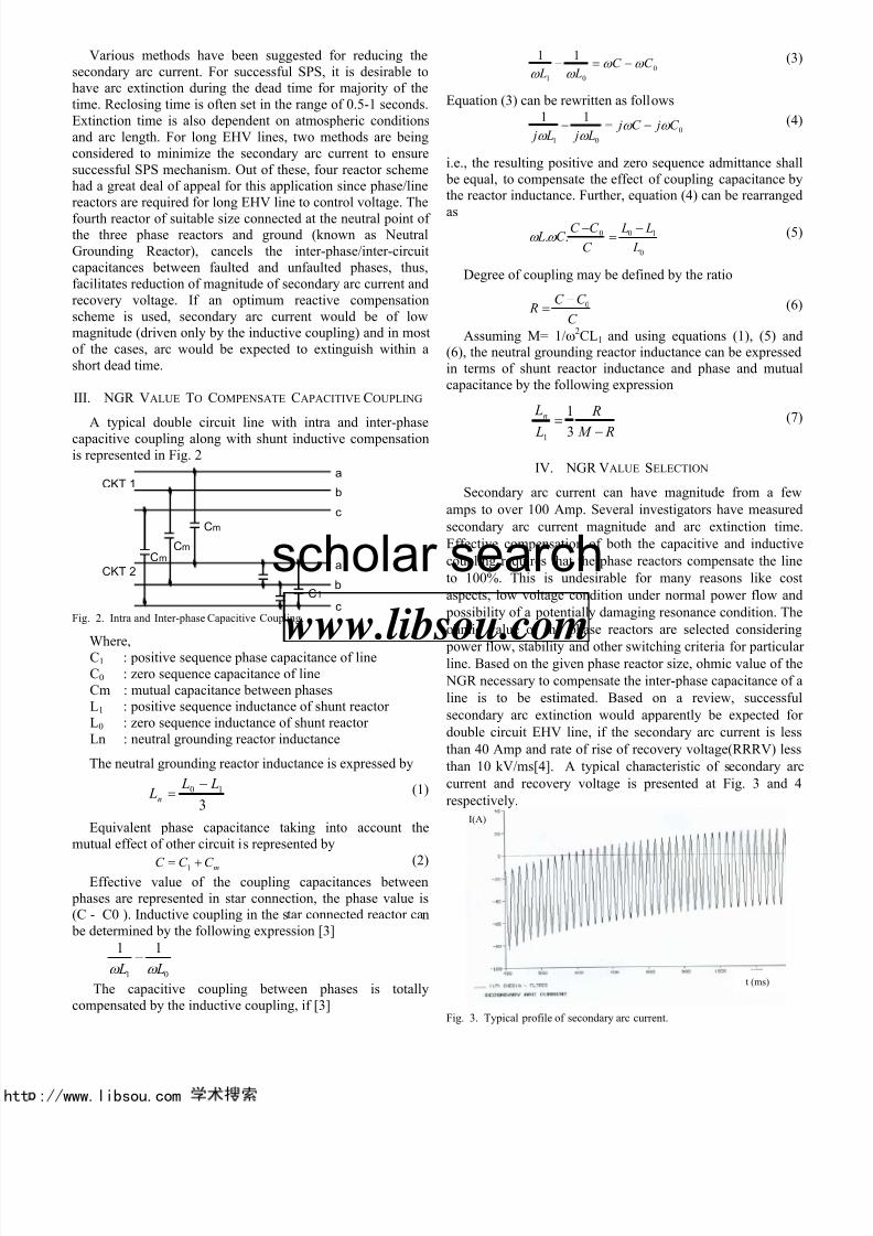
IV. NGR VALUE SELECTION
Secondary arc current can have magnitude from a
amps to over 100 Amp. Several investigators have measu
secondary arc current magnitude and arc extinction ti
Effective compensation of both the capacitive and induc
coupling requires that the phase reactors compensate the
to 100%. This is undesirable for many reasons like c
aspects, low voltage condition under normal power flow
possibility of a potentially damaging resonance condition. T
ohmic value of the phase reactors are selected consider
power flow, stability and other switching criteria for particuline. Based on the given phase reactor size, ohmic value of
NGR necessary to compensate the inter-phase capacitance o
line is to be estimated. Based on a review, succes
secondary arc extinction would apparently be expected
double circuit EHV line, if the secondary arc current is
than 40 Amp and rate of rise of recovery voltage(RRRV) l
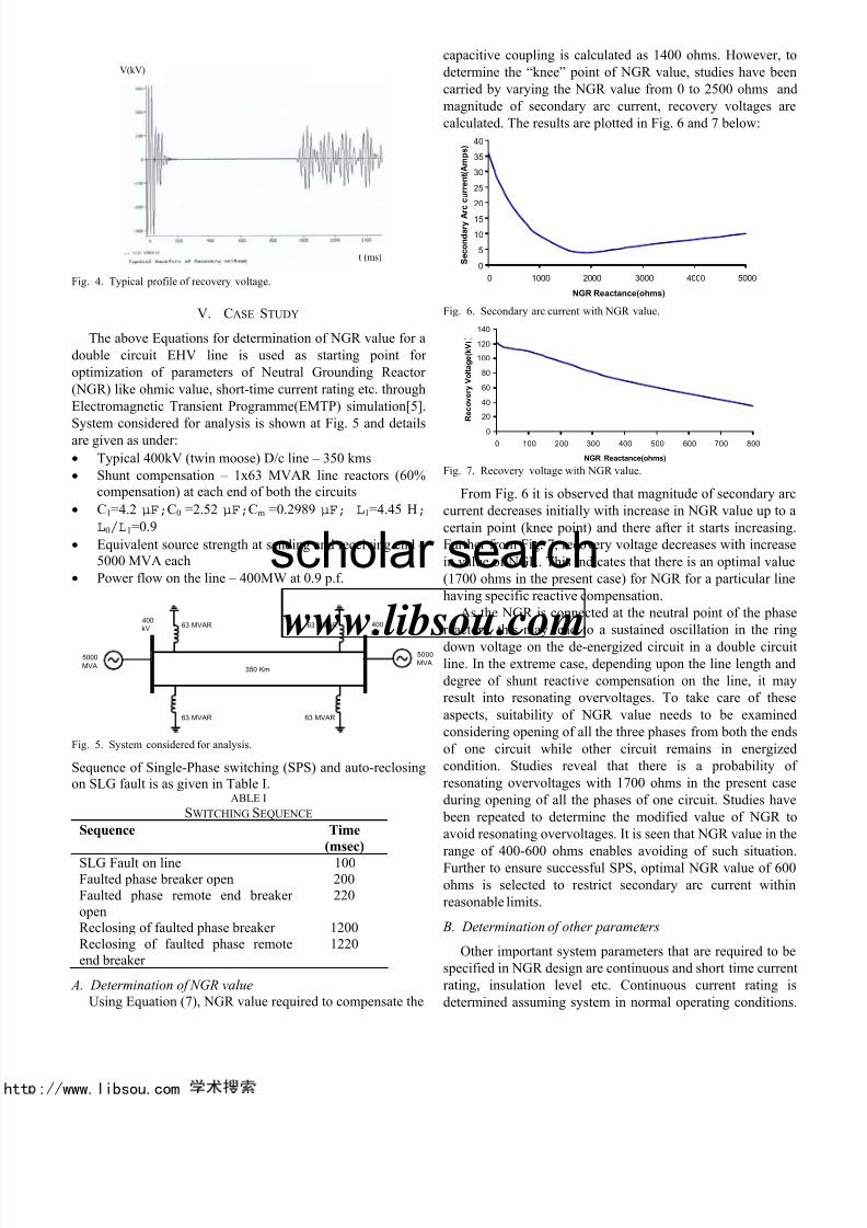
than 10 kV/ms[4]. A typical characteristic of secondary
current and recovery voltage is presented at Fig. 3 and
respectively.
Fig. 3. Typical profile of secondary arc current.
t (ms)
I(A)
htt : www.libsou.com
www.libsou.com
scholar search
5/14/2018 Neutral Gr Reactor - slidepdf.com
http://slidepdf.com/reader/full/neutral-gr-reactor 4/6
htt : www.libsou.com
Fig. 4. Typical profile of recovery voltage.
V. CASE STUDY
The above Equations for determination of NGR value for a
double circuit EHV line is used as starting point for
optimization of parameters of Neutral Grounding Reactor
(NGR) like ohmic value, short-time current rating etc. through
Electromagnetic Transient Programme(EMTP) simulation[5].
System considered for analysis is shown at Fig. 5 and detailsare given as under:
• Typical 400kV (twin moose) D/c line – 350 kms
• Shunt compensation – 1x63 MVAR line reactors (60%compensation) at each end of both the circuits
• C1=4.2 µF;C0 =2.52 µF;Cm =0.2989 µF; L1=4.45 H;
L0/L1=0.9
• Equivalent source strength at sending and receiving end – 5000 MVA each
• Power flow on the line – 400MW at 0.9 p.f.
350 Km
63 MVAR
5000
MVA
400
kV63 MVAR
63 MVAR
63 MVAR 400
kV
5000
MVA
Fig. 5. System considered for analysis.
Sequence of Single-Phase switching (SPS) and auto-reclosingon SLG fault is as given in Table I.
ABLE I
SWITCHING SEQUENCE
Sequence Time
(msec)
SLG Fault on line 100Faulted phase breaker open 200Faulted phase remote end breaker open
220
Reclosing of faulted phase breaker 1200Reclosing of faulted phase remoteend breaker
1220
A. Determination of NGR value
Using Equation (7), NGR value required to compensate the
capacitive coupling is calculated as 1400 ohms. However
determine the “knee” point of NGR value, studies have b
carried by varying the NGR value from 0 to 2500 ohms
magnitude of secondary arc current, recovery voltages
calculated. The results are plotted in Fig. 6 and 7 below:
0
5
10
15
20
25
30
35
40
0 1000 2000 3000 4000 5000
NGR Reactance(ohms)
SecondaryArccurrent(Amps)
Fig. 6. Secondary arc current with NGR value.
0
20
40
60
80
100
120
140
0 100 200 300 400 500 600 700 800
NGR Reactance(ohms)
RecoveryVoltage(kV))
Fig. 7. Recovery voltage with NGR value.
From Fig. 6 it is observed that magnitude of secondary
current decreases initially with increase in NGR value up t
certain point (knee point) and there after it starts increasi
Further from Fig. 7, recovery voltage decreases with incre
in value of NGR. This indicates that there is an optimal va
(1700 ohms in the present case) for NGR for a particular l
having specific reactive compensation.
As the NGR is connected at the neutral point of the ph
reactors, this may lead to a sustained oscillation in the r
down voltage on the de-energized circuit in a double cirline. In the extreme case, depending upon the line length
degree of shunt reactive compensation on the line, it m
result into resonating overvoltages. To take care of th
aspects, suitability of NGR value needs to be exami
considering opening of all the three phases from both the e
of one circuit while other circuit remains in energi
condition. Studies reveal that there is a probability
resonating overvoltages with 1700 ohms in the present c
during opening of all the phases of one circuit. Studies h
been repeated to determine the modified value of NGR
avoid resonating overvoltages. It is seen that NGR value in
range of 400-600 ohms enables avoiding of such situatiFurther to ensure successful SPS, optimal NGR value of
ohms is selected to restrict secondary arc current wit
reasonable limits.
B. Determination of other parameters
Other important system parameters that are required to
specified in NGR design are continuous and short time cur
rating, insulation level etc. Continuous current rating
determined assuming system in normal operating conditio
V(kV)
t (ms)
htt : www.libsou.com
www.libsou.com
scholar search
5/14/2018 Neutral Gr Reactor - slidepdf.com
http://slidepdf.com/reader/full/neutral-gr-reactor 5/6
htt : www.libsou.com
For determination of short-time current rating and insulation
level, methodology applied is given in Table II.TABLE II
SIMULATION SEQUENCE
Sequence Time
(msec)
SLG Fault on line 100Faulted phase breaker open 200Faulted phase remote end breaker open
220
Reclosing of faulted phase breaker 1200Reclosing of faulted phase remoteend breaker
1220
Opening of receiving end breakers (3- poles)
1240
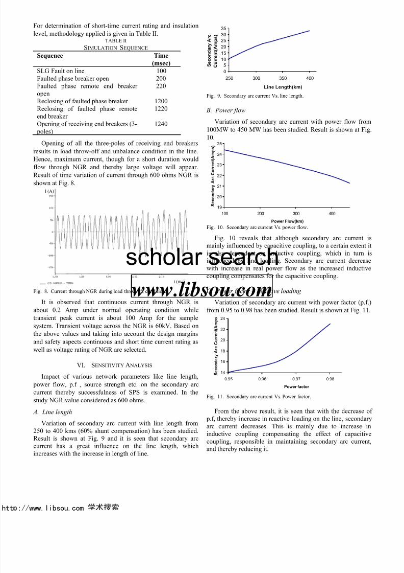
Opening of all the three-poles of receiving end breakers
results in load throw-off and unbalance condition in the line.
Hence, maximum current, though for a short duration would
flow through NGR and thereby large voltage will appear.
Result of time variation of current through 600 ohms NGR is
shown at Fig. 8.
Fig. 8. Current through NGR during load throw-off condition.
It is observed that continuous current through NGR isabout 0.2 Amp under normal operating condition while
transient peak current is about 100 Amp for the sample
system. Transient voltage across the NGR is 60kV. Based on
the above values and taking into account the design margins
and safety aspects continuous and short time current rating as
well as voltage rating of NGR are selected.
VI. SENSITIVITY A NALYSIS
Impact of various network parameters like line length,
power flow, p.f , source strength etc. on the secondary arc
current thereby successfulness of SPS is examined. In the
study NGR value considered as 600 ohms.
A. Line length
Variation of secondary arc current with line length from250 to 400 kms (60% shunt compensation) has been studied.Result is shown at Fig. 9 and it is seen that secondary arccurrent has a great influence on the line length, whichincreases with the increase in length of line.
0
5
10
15
20
25
30
35
250 300 350 400
Line Length(km)
SecondaryArc
Current(Amps)
Fig. 9. Secondary arc current Vs. line length.
B. Power flow
Variation of secondary arc current with power flow fr
100MW to 450 MW has been studied. Result is shown at F
10.
19
20
21
22
23
24
25
100 200 300 400
Power Flow(km)
SecondaryArcCurrent(Amps)
Fig. 10. Secondary arc current Vs. power flow.
Fig. 10 reveals that although secondary arc currentmainly influenced by capacitive coupling, to a certain extenis also dependent on inductive coupling, which in turninfluenced by line loading. Secondary arc current decrewith increase in real power flow as the increased induccoupling compensates for the capacitive coupling.
C. Power factor – Reactive loading
Variation of secondary arc current with power factor (pfrom 0.95 to 0.98 has been studied. Result is shown at Fig.
14
16
18
20
22
24
0.95 0.96 0.97 0.98
Power factor
SecondaryArcCurrent(Amps
Fig. 11. Secondary arc current Vs. Power factor.
From the above result, it is seen that with the decrease p.f, thereby increase in reactive loading on the line, secondarc current decreases. This is mainly due to increaseinductive coupling compensating the effect of capacicoupling, responsible in maintaining secondary arc currand thereby reducing it.
t (ms)
I (A)
htt : www.libsou.com
www.libsou.com
scholar search
5/14/2018 Neutral Gr Reactor - slidepdf.com
http://slidepdf.com/reader/full/neutral-gr-reactor 6/6
htt : www.libsou.com
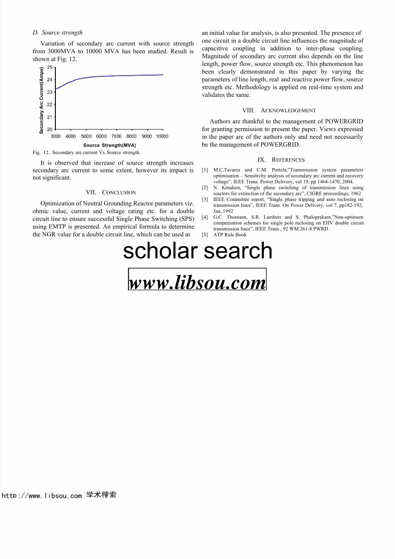
D. Source strength
Variation of secondary arc current with source strength
from 3000MVA to 10000 MVA has been studied. Result is
shown at Fig. 12.
20
21
22
23
24
25
3000 4000 500 0 600 0 70 00 8000 9000 10000
Source Strength(MVA)
SecondaryArcCurrent(Amps)
Fig. 12. Secondary arc current Vs. Source strength.
It is observed that increase of source strength increasessecondary arc current to some extent, however its impact isnot significant.
VII.
CONCLUSION Optimization of Neutral Grounding Reactor parameters viz.
ohmic value, current and voltage rating etc. for a double
circuit line to ensure successful Single Phase Switching (SPS)
using EMTP is presented. An empirical formula to determine
the NGR value for a double circuit line, which can be used as
an initial value for analysis, is also presented. The presence
one circuit in a double circuit line influences the magnitud
capacitive coupling in addition to inter-phase coupli
Magnitude of secondary arc current also depends on the
length, power flow, source strength etc. This phenomenon
been clearly demonstrated in this paper by varying
parameters of line length, real and reactive power flow, sou
strength etc. Methodology is applied on real-time system
validates the same.
VIII. ACKNOWLEDGEMENT
Authors are thankful to the management of POWERGR
for granting permission to present the paper. Views expres
in the paper are of the authors only and need not necessa
be the management of POWERGRID.
IX. R EFERENCES
[1] M.C.Tavares and C.M. Portela,”Transmission system paramoptimisation – Sensitivity analysis of secondary arc current and recovoltage”, IEEE Trans. Power Delivery, vol 19, pp 1464-1470, 2004.
[2] N. Knudsen, “Single phase switching of transmission lines
reactors for extinction of the secondary arc”, CIGRE proceedings, 19[3] IEEE Committee report, “Single phase tripping and auto reclosingtransmission lines”, IEEE Trans. On Power Delivery, vol 7, pp182-Jan, 1992
[4] G.C. Thomann, S.R. Lambert and S. Phaloprakarn,”Non-optimcompensation schemes for single pole reclosing on EHV double citransmission lines”, IEEE Trans., 92 WM 261-8 PWRD .
[5] ATP Rule Book
htt : www libsou com
www.libsou.com
scholar search