Embed Size (px)
Citation preview
1
By John Devoldere, ON4UNBy John Devoldere, ON4UNRobye Lahlum, W1MKRobye Lahlum, W1MK
Roger Vermet, ON6WURoger Vermet, ON6WU© ON4UN
Arrays on Low Bands often have all Arrays on Low Bands often have all elements fedelements fedNot necessarily: see N7JWNot necessarily: see N7JWWhat is the best feed method?What is the best feed method?
Easiest, Easiest, ““plug and playplug and play””Most flexible (optimized results)Most flexible (optimized results)How much better ?How much better ?
NEW FEED SYSTEM FOR ARRAYSNEW FEED SYSTEM FOR ARRAYS
© ON4UN

2
PHASING ANGLE & LINE LENGTHPHASING ANGLE & LINE LENGTH
In the past: In the past: phase delay = phase delay = cable lengthcable lengthIS WRONG IS WRONG (in most cases)(in most cases)
© ON4UN
BREAKTHROUGHSBREAKTHROUGHS
Forest Gehrke Forest Gehrke –– K2BTK2BT-- Ham Radio 1983Ham Radio 1983
W2CQH: the hybrid coupler QST Jan 1978W2CQH: the hybrid coupler QST Jan 1978
© ON4UN
3
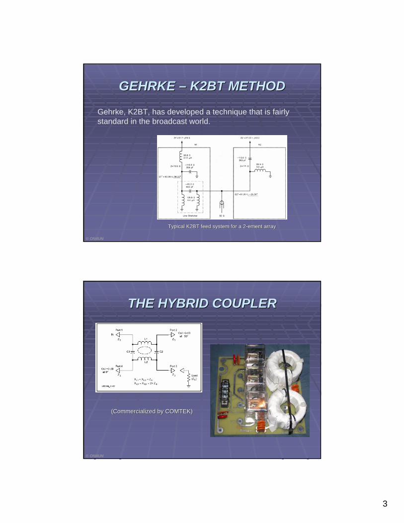
GEHRKE GEHRKE –– K2BT METHODK2BT METHOD
Gehrke, K2BT, has developed a technique that is fairly standard in the broadcast world.
Typical K2BT feed system for a 2Typical K2BT feed system for a 2--ement arrayement array
© ON4UN
THE HYBRID COUPLERTHE HYBRID COUPLER
© ON4UN
(Commercialized by COMTEK)(Commercialized by COMTEK)
4
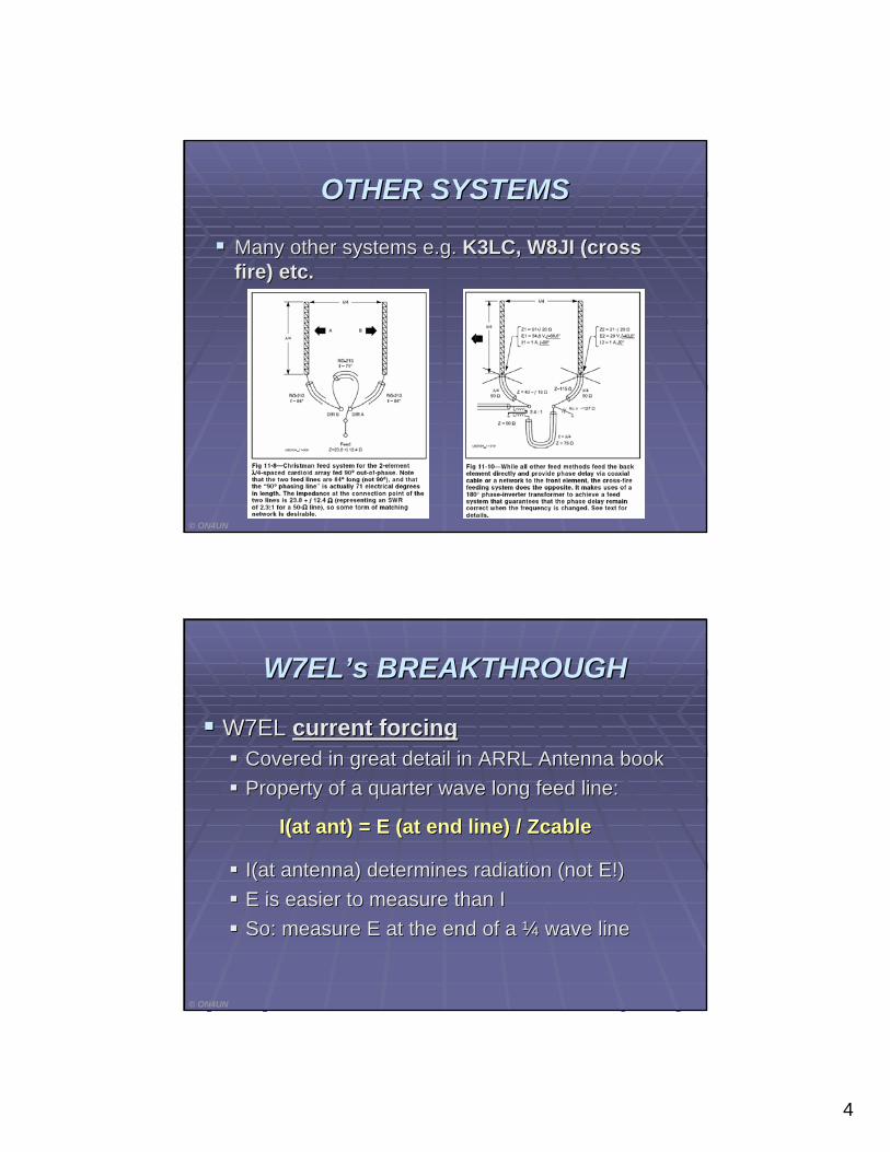
OTHER SYSTEMSOTHER SYSTEMS
Many other systems e.g. Many other systems e.g. K3LC, W8JI (cross K3LC, W8JI (cross fire) etc.fire) etc.
© ON4UN
W7ELW7EL’’s BREAKTHROUGHs BREAKTHROUGH
W7EL W7EL current forcingcurrent forcingCovered in great detail in ARRL Antenna bookCovered in great detail in ARRL Antenna bookProperty of a quarter wave long feed line:Property of a quarter wave long feed line:
I(at ant) = E (at end line) I(at ant) = E (at end line) / Zcable/ Zcable
I(at antenna) determines radiation (not E!)I(at antenna) determines radiation (not E!)E is easier to measure than IE is easier to measure than ISo: measure E at the end of a So: measure E at the end of a ¼¼ wave linewave line
© ON4UN

5
NOW: FULL DESIGN FREEDOMNOW: FULL DESIGN FREEDOM
W7EL W7EL L networkL network →→ W1MK L networkW1MK L network
Until now formulas available only for quadrature feed Until now formulas available only for quadrature feed but with any feed current magnitudebut with any feed current magnitude
( ( QuadratureQuadrature = in increments of 90 deg )= in increments of 90 deg )
Now W1MK developed the mathematics that apply Now W1MK developed the mathematics that apply for any for any magnitudemagnitude and phase angleand phase angle
It really is a Gehrke equivalent (= FULL DESIGN It really is a Gehrke equivalent (= FULL DESIGN FREEDOM) where all networks are combined in a FREEDOM) where all networks are combined in a single single L networkL network
© ON4UN
WHY?WHY?
Why do we want Why do we want ““anyany”” magnitudemagnitude and phase and phase angle?angle?
More design freedom for improved performanceMore design freedom for improved performance
LetLet’’s analyze the well s analyze the well knownknown 44--square arraysquare array
© ON4UN
6
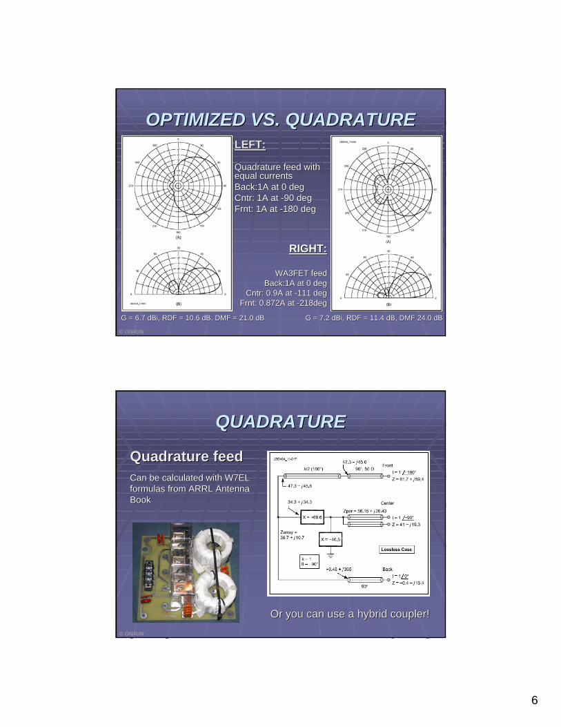
OPTIMIZED VS. QUADRATUREOPTIMIZED VS. QUADRATURE
G = 6.7 dBi, RDF = 10.6 dB, DMF = 21.0 dBG = 6.7 dBi, RDF = 10.6 dB, DMF = 21.0 dB
RIGHT:RIGHT:
WA3FET feedWA3FET feedBack:1A at 0 degBack:1A at 0 deg
CntrCntr: 0.9A at : 0.9A at --111 deg111 degFrntFrnt: 0.872A at : 0.872A at --218deg218deg
G = 7.2 dBi, RDF = 11.4 dB, DMF 24.0 dBG = 7.2 dBi, RDF = 11.4 dB, DMF 24.0 dB
LEFT:LEFT:
Quadrature feed with Quadrature feed with equal currentsequal currentsBack:1A at 0 degBack:1A at 0 degCntr: 1A at Cntr: 1A at --90 deg90 degFrnt: 1A at Frnt: 1A at --180 deg180 deg
© ON4UN
QUADRATUREQUADRATURE
Quadrature feedQuadrature feed
Or you can use a hybrid coupler!Or you can use a hybrid coupler!
Can be calculated with W7EL Can be calculated with W7EL formulas from ARRL Antenna formulas from ARRL Antenna BookBook
© ON4UN
7
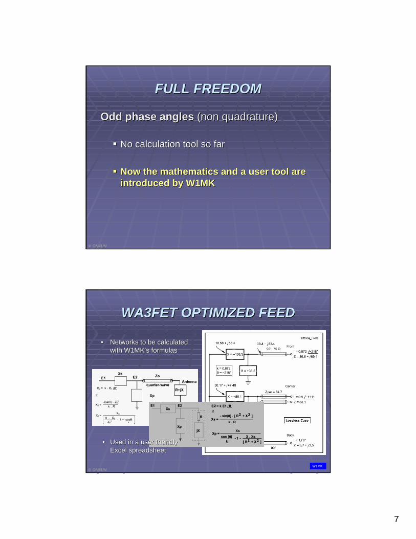
FULL FREEDOMFULL FREEDOM
Odd phase anglesOdd phase angles (non (non quadraturequadrature))
No calculation tool so farNo calculation tool so far
Now the mathematics and a user tool are Now the mathematics and a user tool are introduced by W1MKintroduced by W1MK
© ON4UN
WA3FET OPTIMIZED FEEDWA3FET OPTIMIZED FEED
•• Networks to be calculated Networks to be calculated with W1MKwith W1MK’’s formulass formulas
•• Used in a user friendly Used in a user friendly Excel spreadsheetExcel spreadsheet
© ON4UNW1MK
8
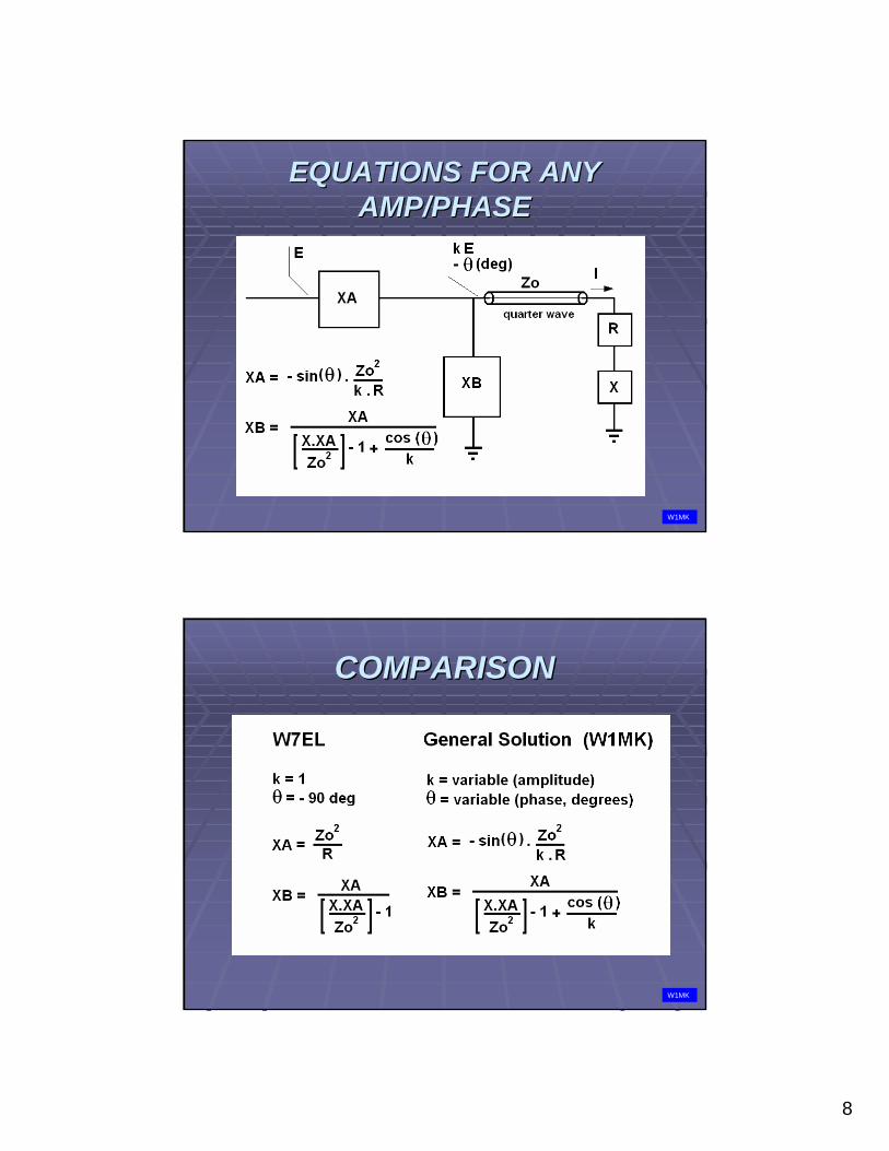
EQUATIONS FOR ANY EQUATIONS FOR ANY AMP/PHASEAMP/PHASE
W1MK
COMPARISONCOMPARISON
W1MK
9
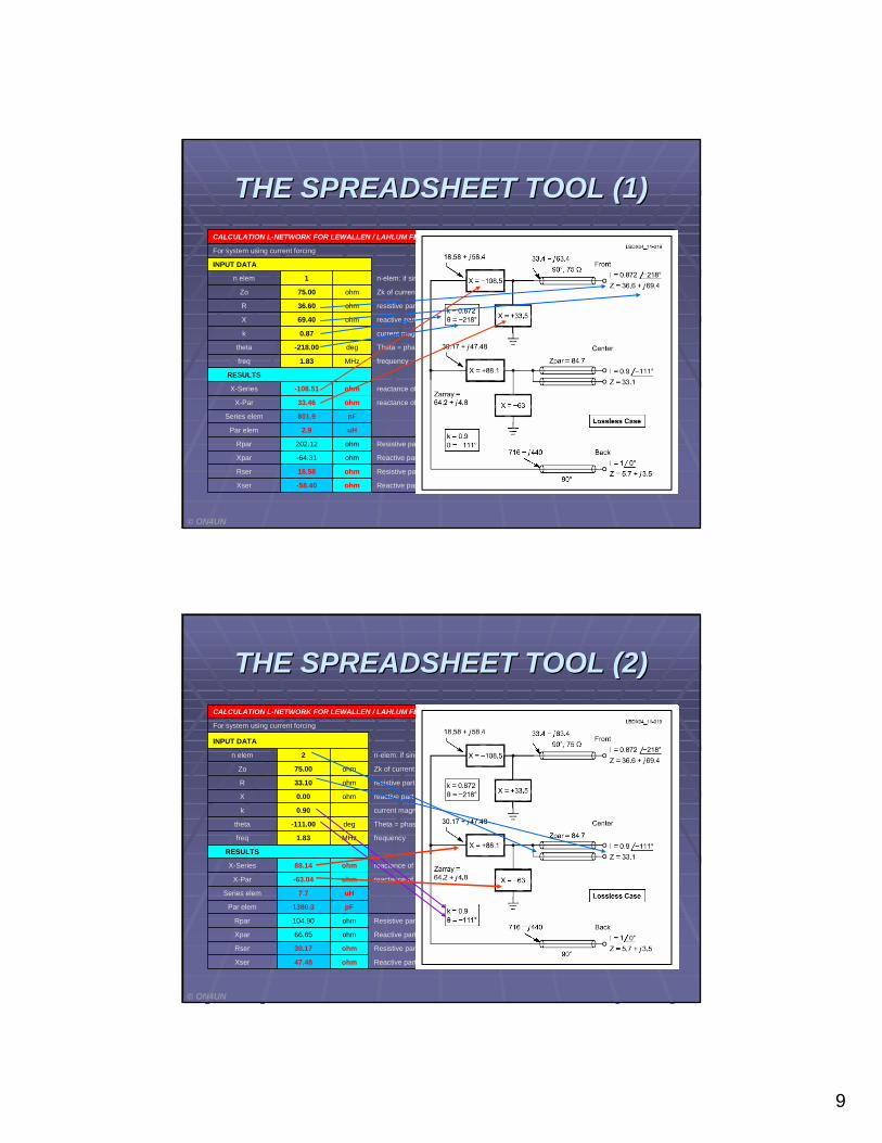
THE SPREADSHEET TOOL (1)THE SPREADSHEET TOOL (1)
Reactive part of parallel impedance at input of L-networkohm-58.40Xser
Resistive part of parallel impedance at input of L-networkohm18.58Rser
Reactive part of parallel impedance at input of L-networkohm-64.31Xpar
Resistive part of parallel impedance at input of L-networkohm202.12Rpar
uH2.9Par elem
pF801.9Series elem
reactance of parallel element in L-networkohm33.46X-Par
reactance of series element in L-networkohm-108.51X-Series
RESULTS
frequencyMHz1.83freq
Theta = phase shift to be obtained with the L-networkdeg-218.00theta
current magnitude coefficient0.87k
reactive part of impedance of element fed through L networkohm69.40X
resistive part of impedance of elem fed through L networkohm36.60R
Zk of current forcing feed linesohm75.00Zo
n-elem: if single line, enter 1, if dual line, enter 2, etc1n elem
INPUT DATA
For system using current forcing
CALCULATION L-NETWORK FOR LEWALLEN / LAHLUM FEED
© ON4UN
THE SPREADSHEET TOOL (2)THE SPREADSHEET TOOL (2)
Reactive part of parallel impedance at input of L-networkohm47.48Xser
Resistive part of parallel impedance at input of L-networkohm30.17Rser
Reactive part of parallel impedance at input of L-networkohm66.65Xpar
Resistive part of parallel impedance at input of L-networkohm104.90Rpar
pF1380.3Par elem
uH7.7Series elem
reactance of parallel element in L-networkohm-63.04X-Par
reactance of series element in L-networkohm88.14X-Series
RESULTS
frequencyMHz1.83freq
Theta = phase shift to be obtained with the L-networkdeg-111.00theta
current magnitude coefficient0.90k
reactive part of impedance of element fed through L networkohm0.00X
resistive part of impedance of elem fed through L networkohm33.10R
Zk of current forcing feed linesohm75.00Zo
n-elem: if single line, enter 1, if dual line, enter 2, etc2n elem
INPUT DATA
For system using current forcing
CALCULATION L-NETWORK FOR LEWALLEN / LAHLUM FEED
© ON4UN
10
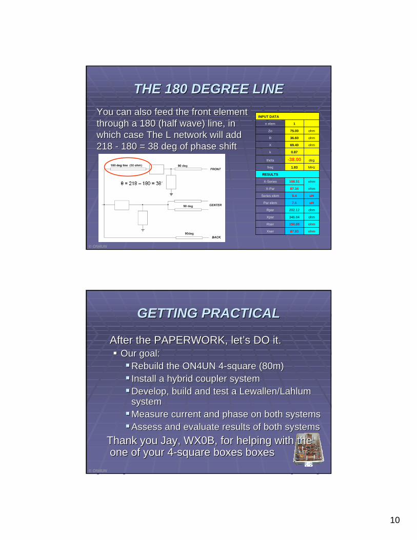
THE 180 DEGREE LINETHE 180 DEGREE LINEYou can also feed the front element You can also feed the front element through a 180 (half wave) line, in through a 180 (half wave) line, in which case The L network will add which case The L network will add 218 218 -- 180 = 38 deg of phase shift180 = 38 deg of phase shift
ohm87.93Xser
ohm150.88Rser
ohm346.84Xpar
ohm202.12Rpar
uH7.6Par elem
uH9.4Series elem
ohm87.34X-Par
ohm108.51X-Series
RESULTS
MHz1.83freq
deg-38.00theta
0.87k
ohm69.40X
ohm36.60R
ohm75.00Zo
1n elem
INPUT DATA
© ON4UN
GETTING PRACTICALGETTING PRACTICAL
After the PAPERWORK, letAfter the PAPERWORK, let’’s DO it.s DO it.Our goal:Our goal:
Rebuild the ON4UN 4Rebuild the ON4UN 4--square (80m)square (80m)Install a hybrid coupler systemInstall a hybrid coupler systemDevelop, build and test a Lewallen/Lahlum Develop, build and test a Lewallen/Lahlum systemsystemMeasure current and phase on both systemsMeasure current and phase on both systemsAssess and evaluate results of both systemsAssess and evaluate results of both systems
Thank you Jay, WX0B, for helping with the Thank you Jay, WX0B, for helping with the one of your 4one of your 4--square boxes square boxes boxesboxes
© ON4UN
11
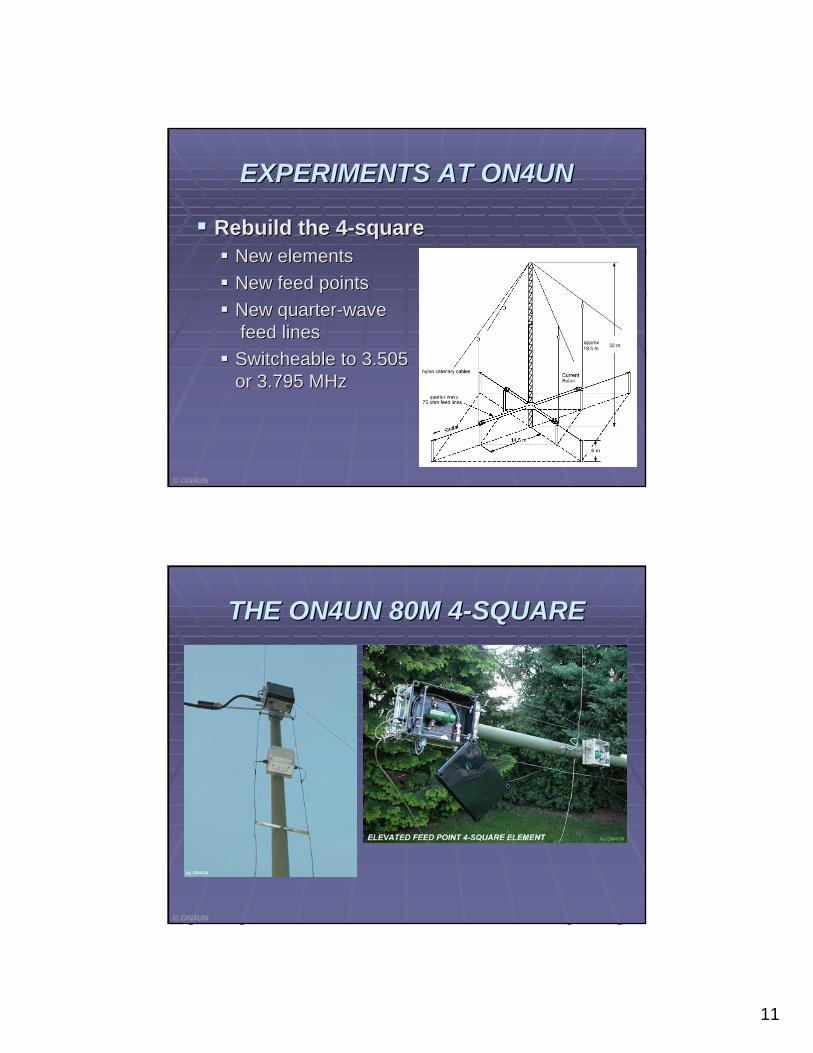
EXPERIMENTS AT ON4UNEXPERIMENTS AT ON4UN
Rebuild the 4Rebuild the 4--squaresquareNew elementsNew elementsNew feed pointsNew feed pointsNew quarterNew quarter--wavewavefeed linesfeed lines
SwitcheableSwitcheable to 3.505to 3.505or 3.795 MHzor 3.795 MHz
© ON4UN
THE ON4UN 80M 4THE ON4UN 80M 4--SQUARESQUARE
© ON4UN
12
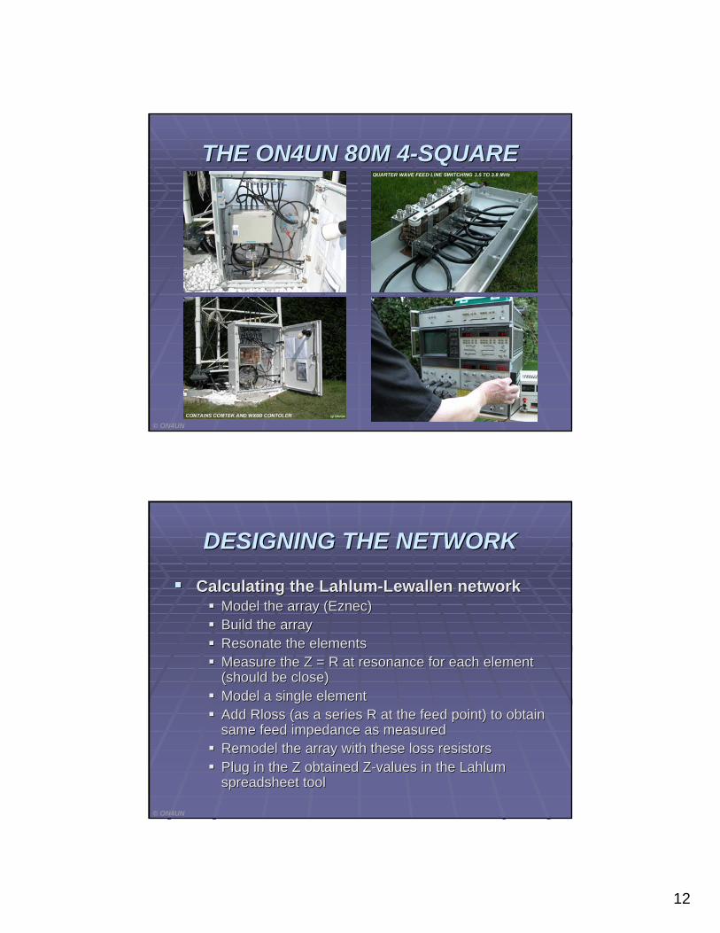
THE ON4UN 80M 4THE ON4UN 80M 4--SQUARESQUARE
© ON4UN
DESIGNING THE NETWORKDESIGNING THE NETWORK
Calculating the LahlumCalculating the Lahlum--Lewallen networkLewallen networkModel the array (Eznec)Model the array (Eznec)Build the arrayBuild the arrayResonate the elements Resonate the elements Measure the Measure the Z = RZ = R at resonance for each element at resonance for each element (should be close)(should be close)Model a single elementModel a single elementAdd Rloss (as a series R at the feed point) to obtain Add Rloss (as a series R at the feed point) to obtain same feed impedance as measuredsame feed impedance as measuredRemodel the array with these loss resistorsRemodel the array with these loss resistorsPlug in the Z obtained ZPlug in the Z obtained Z--values in the Lahlum values in the Lahlum spreadsheet toolspreadsheet tool
© ON4UN
13
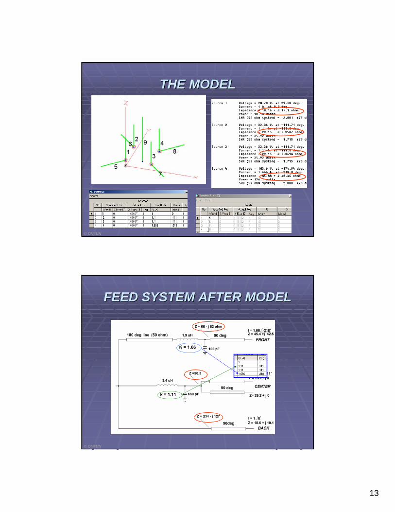
THE MODELTHE MODEL
© ON4UN
FEED SYSTEM AFTER MODELFEED SYSTEM AFTER MODEL
© ON4UN
14
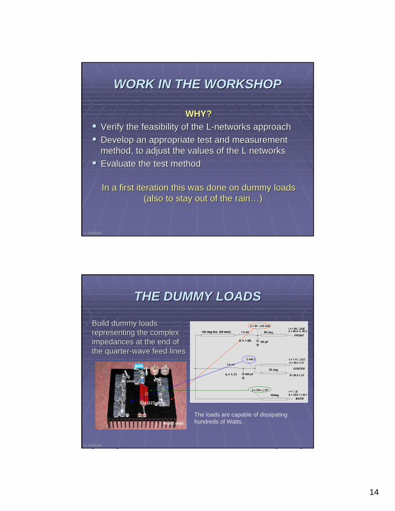
WORK IN THE WORKSHOPWORK IN THE WORKSHOP
WHY?WHY?Verify the feasibility of the LVerify the feasibility of the L--networks approachnetworks approachDevelop an appropriate test and measurement Develop an appropriate test and measurement method, to adjust the values of the L networksmethod, to adjust the values of the L networksEvaluate the test methodEvaluate the test method
In a first iteration this was done on dummy loads In a first iteration this was done on dummy loads (also to stay out of the rain(also to stay out of the rain……))
© ON4UN
THE DUMMY LOADSTHE DUMMY LOADS
© ON4UN
Build dummy loads Build dummy loads representing the complex representing the complex impedances at the end of impedances at the end of the quarterthe quarter--wave feed lineswave feed lines
97 ohm
234-j127 ohm
66-j62 ohm
The loads are capable of dissipating hundreds of Watts.
15
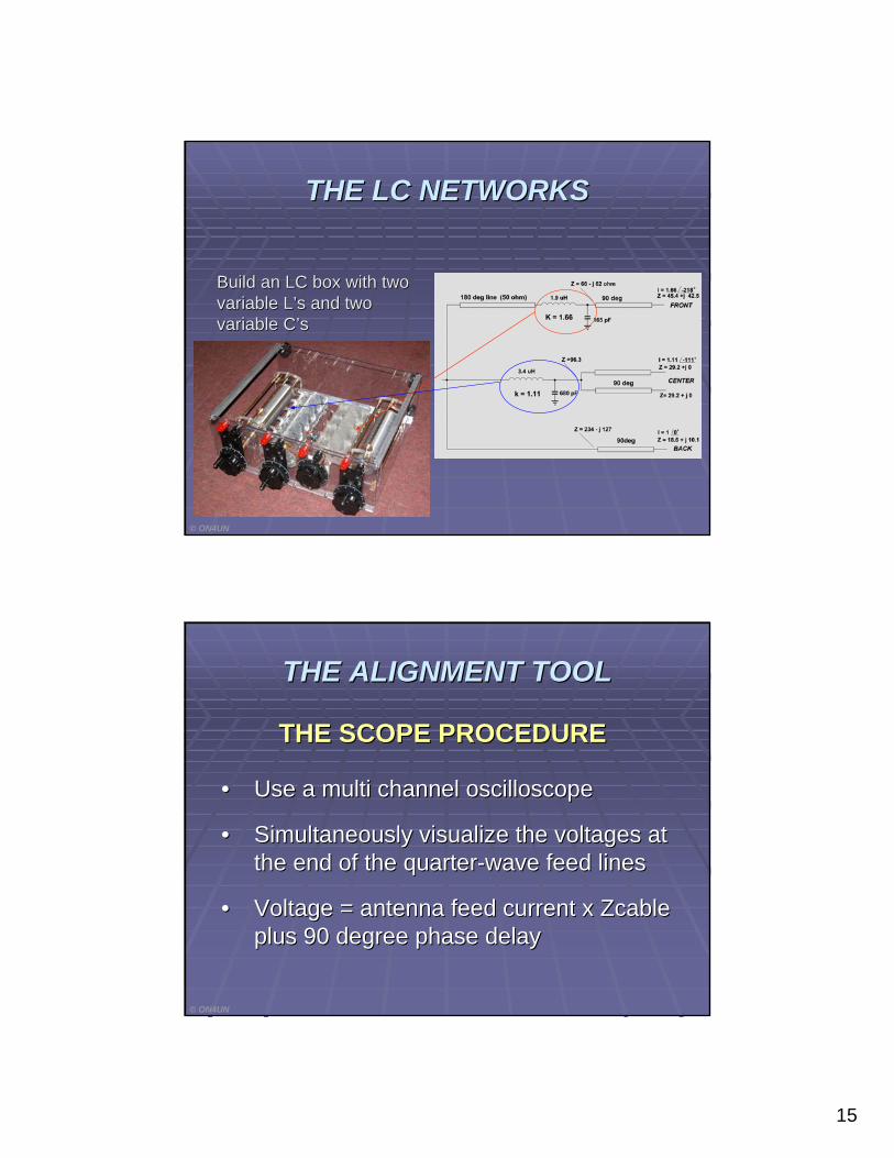
THE LC NETWORKSTHE LC NETWORKS
© ON4UN
Build an LC box with two Build an LC box with two variable Lvariable L’’s and two s and two variable Cvariable C’’ss
THE ALIGNMENT TOOLTHE ALIGNMENT TOOL
THE SCOPE PROCEDURETHE SCOPE PROCEDURE
•• Use a multi channel oscilloscopeUse a multi channel oscilloscope
•• Simultaneously visualize the voltages at Simultaneously visualize the voltages at the end of the quarterthe end of the quarter--wave feed lineswave feed lines
•• Voltage = antenna feed current x Voltage = antenna feed current x ZcableZcableplus 90 degree phase delayplus 90 degree phase delay
© ON4UN
16
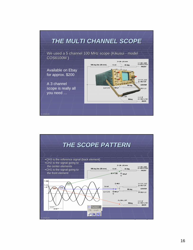
THE MULTI CHANNEL SCOPETHE MULTI CHANNEL SCOPE
Available on Ebayfor approx. $200
A 3 channel scope is really all you need …
© ON4UN
We used a 5 channel 100 MHz scope (We used a 5 channel 100 MHz scope (KikusuiKikusui -- model model COS6100MCOS6100M )
THE SCOPE PATTERNTHE SCOPE PATTERN
•• CH3 is the reference signal (back element)CH3 is the reference signal (back element)•• CH2 is the signal going to CH2 is the signal going to
the center elementsthe center elements•• CH1 is the signal going to CH1 is the signal going to
the front elementthe front element
© ON4UN
17
© ON4UN
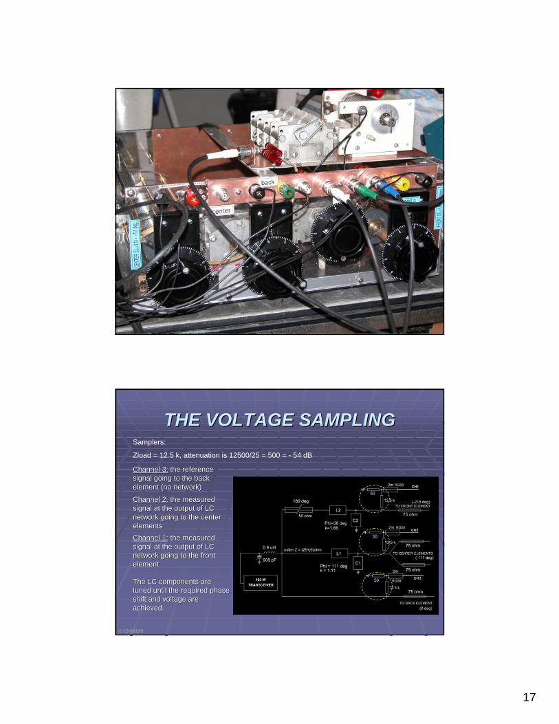
THE VOLTAGE SAMPLINGTHE VOLTAGE SAMPLINGSamplers:
Zload = 12.5 k, attenuation is 12500/25 = 500 = - 54 dB
The LC components are The LC components are tuned until the required phase tuned until the required phase shift and voltage are shift and voltage are achieved.achieved.
Channel 3:Channel 3: the reference the reference signal going to the back signal going to the back element (no network)element (no network)
Channel 2:Channel 2: the measured the measured signal at the output of LC signal at the output of LC network going to the center network going to the center elementselements
© ON4UN
Channel 1:Channel 1: the measured the measured signal at the output of LC signal at the output of LC network going to the front network going to the front elementelement
18
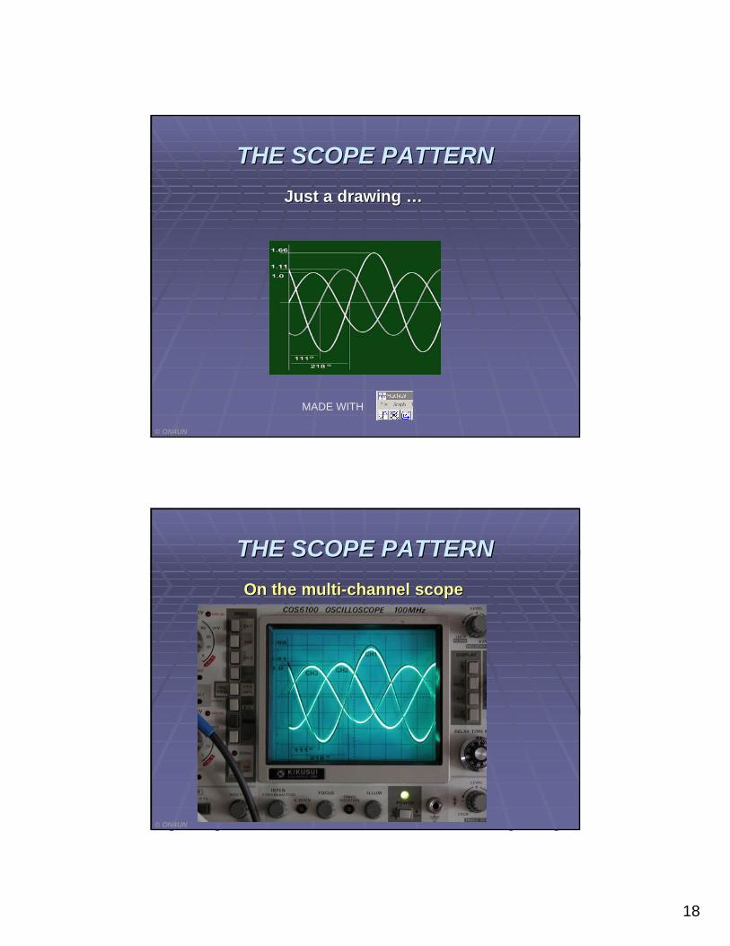
THE SCOPE PATTERNTHE SCOPE PATTERN
© ON4UN
Just a drawing Just a drawing ……
MADE WITH
MADE WITH
THE SCOPE PATTERNTHE SCOPE PATTERNOn the multiOn the multi--channel scopechannel scope
© ON4UN
19
NEW FEED SYSTEM FOR ARRAYSNEW FEED SYSTEM FOR ARRAYS
© ON4UN
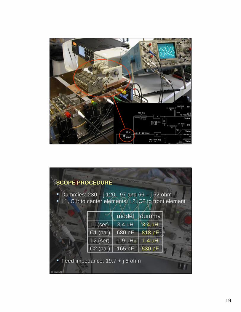
530 pF530 pF165 pF165 pFC2 (par)C2 (par)1.4 uH1.4 uH1.9 uH1.9 uHL2 (ser)L2 (ser)818 pF818 pF680 pF680 pFC1 (par)C1 (par)3.4 uH3.4 uH3.4 uH3.4 uHL1(ser)L1(ser)
dummydummymodelmodel
© ON4UN
SCOPE PROCEDURESCOPE PROCEDURE
Dummies: 230 Dummies: 230 –– j 120, 97 and 66 j 120, 97 and 66 –– j 62 ohmj 62 ohmL1, C1: to center elements, L2, C2 to front elementL1, C1: to center elements, L2, C2 to front element
Feed impedance: 19.7 + j 8 ohmFeed impedance: 19.7 + j 8 ohm

20
© ON4UN
ALIGNMENT PROCEDURE WAS VALIDATEDALIGNMENT PROCEDURE WAS VALIDATED
ALIGNMENT EASY BUT CRITICAL (TOUCHY)ALIGNMENT EASY BUT CRITICAL (TOUCHY)
NEXT STEP:NEXT STEP:
WAIT FOR BETTER WX AND GO OUT IN THE FIELDWAIT FOR BETTER WX AND GO OUT IN THE FIELD
A CONCLUSIONA CONCLUSION
© ON4UN
21
© ON4UN
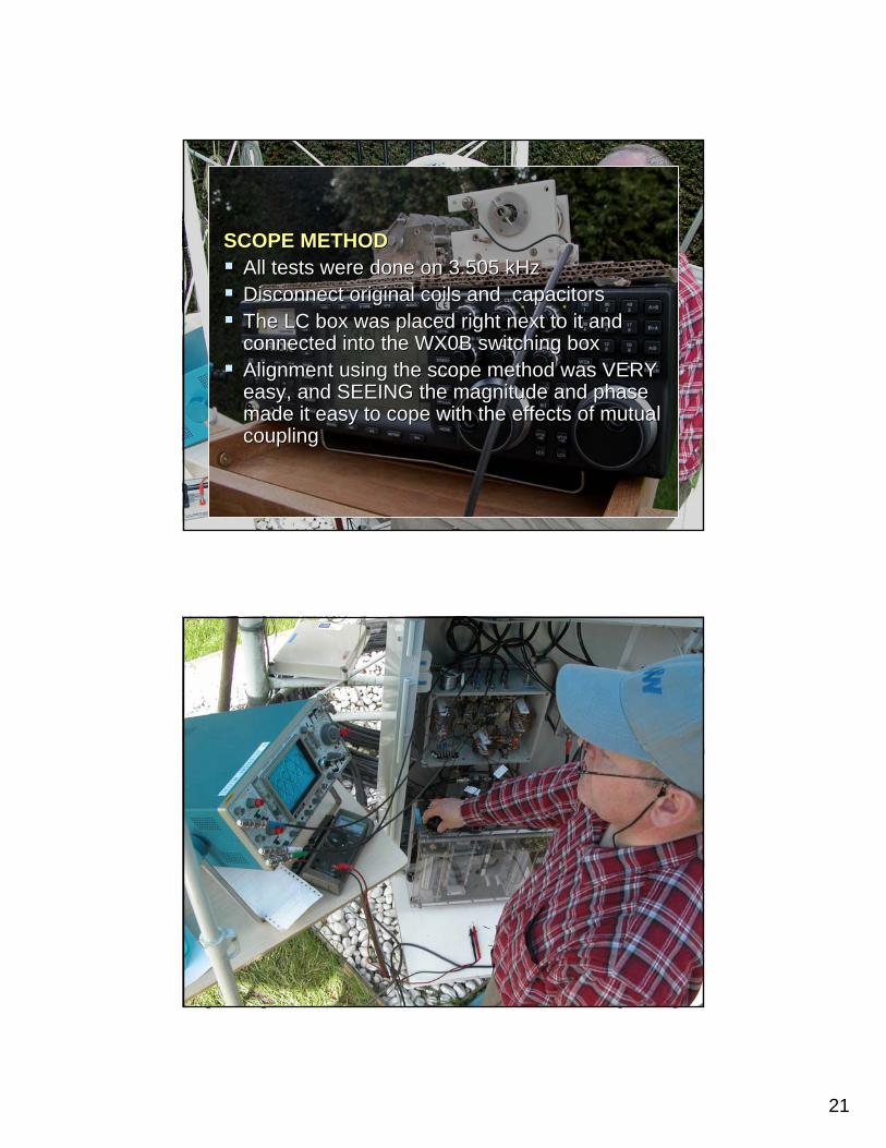
SCOPE METHODSCOPE METHODAll tests were done on 3.505 kHzAll tests were done on 3.505 kHzDisconnect original coils and Disconnect original coils and capacitorscapacitorsThe LC box was placed right next to it and The LC box was placed right next to it and connected into the WX0B switching boxconnected into the WX0B switching boxAlignment using the scope method was VERY Alignment using the scope method was VERY easy, and SEEING the easy, and SEEING the magnitudemagnitude andand phase phase made it easy to cope with the effects of mutual made it easy to cope with the effects of mutual couplingcoupling
22
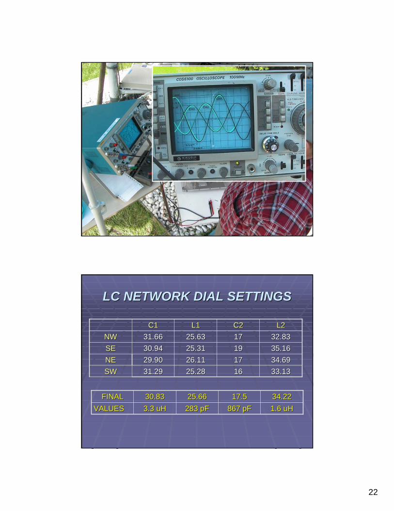
LC NETWORK DIAL SETTINGSLC NETWORK DIAL SETTINGS
33.1333.13161625.2825.2831.2931.29SWSW34.6934.69171726.1126.1129.9029.90NENE35.1635.16191925.3125.3130.9430.94SESE32.8332.83171725.6325.6331.6631.66NWNW
L2L2C2C2L1L1C1C1
1.6 1.6 uHuH867 867 pFpF283 283 pFpF3.3 3.3 uHuHVALUESVALUES34.2234.2217.517.525.6625.6630.8330.83FINALFINAL
23
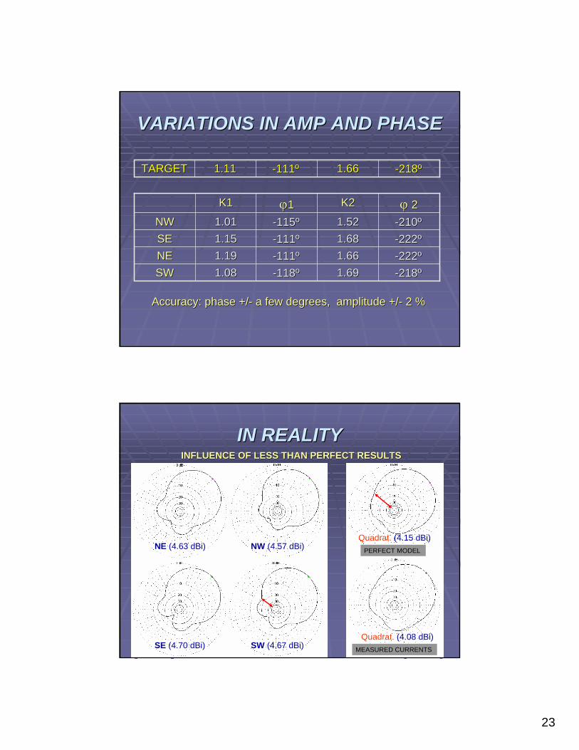
VARIATIONS IN AMP AND PHASEVARIATIONS IN AMP AND PHASE
--218218ºº1.691.69--118118ºº1.081.08SWSW--222222ºº1.661.66--111111ºº1.191.19NENE--222222ºº1.681.68--111111ºº1.151.15SESE--210210ºº1.521.52--115115ºº1.011.01NWNWϕϕ 22K2K2ϕϕ11K1K1
--218218ºº1.661.66--111111ºº1.111.11TARGETTARGET
Accuracy: phase +/Accuracy: phase +/-- a few degrees, amplitude +/a few degrees, amplitude +/-- 2 %2 %
INFLUENCE OF LESS THAN PERFECT RESULTSINFLUENCE OF LESS THAN PERFECT RESULTS
NE (4.63 dBi) NW (4.57 dBi)
SE (4.70 dBi) SW (4.67 dBi)
Quadrat. (4.15 dBi)
Quadrat. (4.08 dBi)
PERFECT MODEL
MEASURED CURRENTS
IN REALITYIN REALITY
24
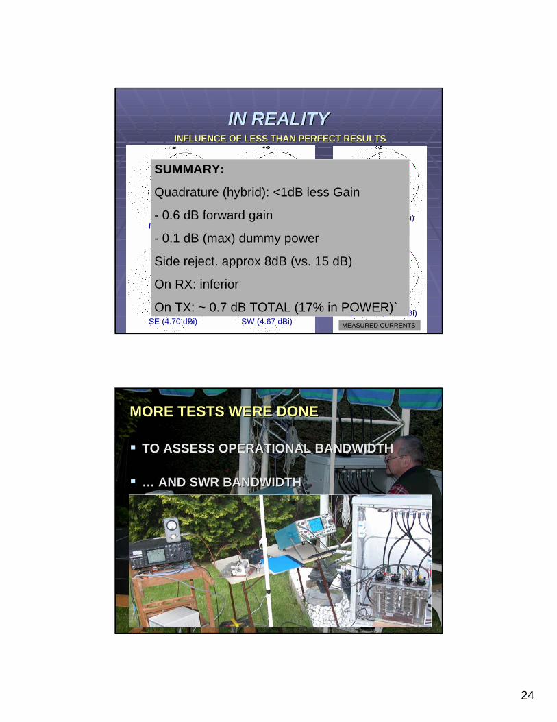
INFLUENCE OF LESS THAN PERFECT RESULTSINFLUENCE OF LESS THAN PERFECT RESULTS
NE (4.63 dBi) NW (4.57 dBi)
SE (4.70 dBi) SW (4.67 dBi)
Quadrat. (4.15 dBi)
Quadrat. (4.08 dBi)
PERFECT MODEL
MEASURED CURRENTS
SUMMARY:
Quadrature (hybrid): <1dB less Gain
- 0.6 dB forward gain
- 0.1 dB (max) dummy power
Side reject. approx 8dB (vs. 15 dB)
On RX: inferior
On TX: ~ 0.7 dB TOTAL (17% in POWER)`
IN REALITYIN REALITY
MORE TESTS WERE DONE MORE TESTS WERE DONE
TO ASSESS OPERATIONAL BANDWIDTHTO ASSESS OPERATIONAL BANDWIDTH
…… AND SWR BANDWIDTHAND SWR BANDWIDTH
25
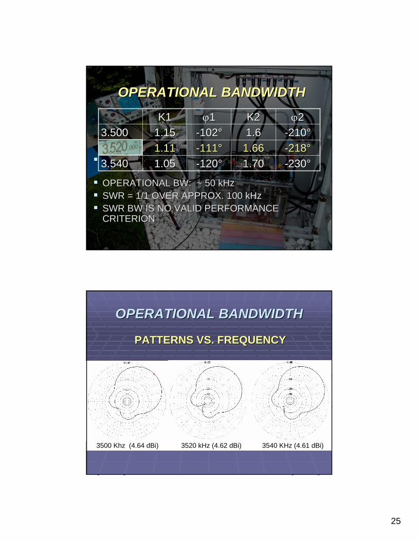
OPERATIONAL BW: ~ 50 kHz OPERATIONAL BW: ~ 50 kHz SWR = 1/1 OVER APPROX. 100 kHzSWR = 1/1 OVER APPROX. 100 kHzSWR BW IS NO VALID PERFORMANCE SWR BW IS NO VALID PERFORMANCE CRITERIONCRITERION
--230230°°1.701.70--120120°°1.051.053.5403.540--218218°°1.661.66--111111°°1.111.113.5203.520--210210°°1.61.6--102102°°1.151.153.5003.500ϕϕ22K2K2ϕϕ11K1K1
OPERATIONAL BANDWIDTHOPERATIONAL BANDWIDTH
OPERATIONAL BANDWIDTHOPERATIONAL BANDWIDTH
PATTERNS VS. FREQUENCYPATTERNS VS. FREQUENCY
3500 Khz (4.64 dBi) 3520 kHz (4.62 dBi) 3540 KHz (4.61 dBi)
26
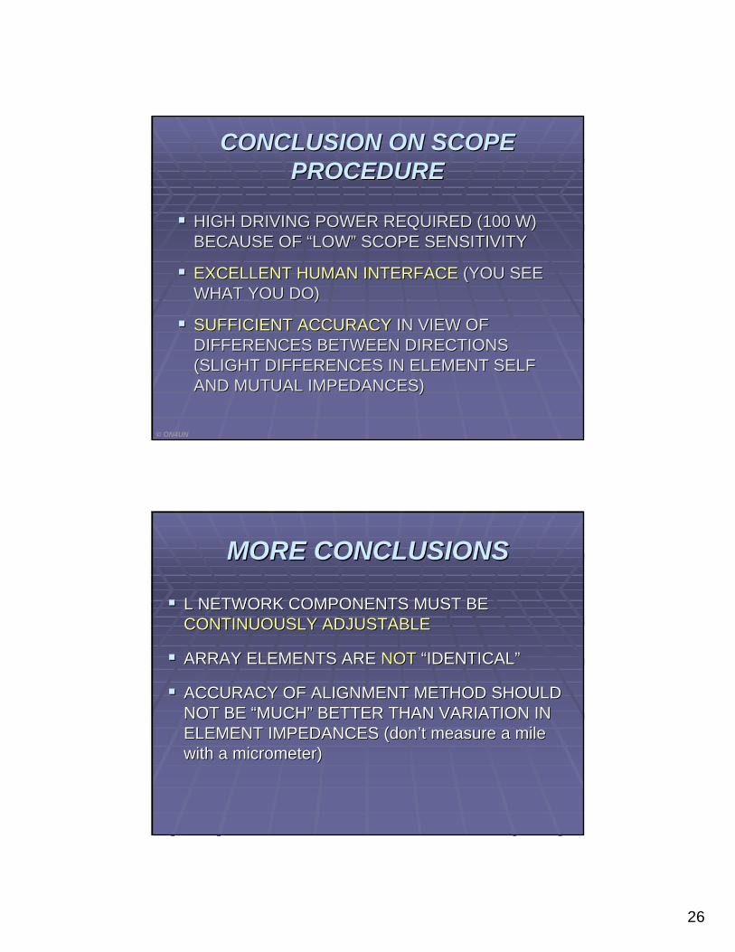
CONCLUSION ON SCOPE CONCLUSION ON SCOPE PROCEDUREPROCEDURE
HIGH DRIVING POWER REQUIRED (100 W) HIGH DRIVING POWER REQUIRED (100 W) BECAUSE OF BECAUSE OF ““LOWLOW”” SCOPE SENSITIVITYSCOPE SENSITIVITY
EXCELLENT HUMAN INTERFACEEXCELLENT HUMAN INTERFACE (YOU SEE (YOU SEE WHAT YOU DO)WHAT YOU DO)
SUFFICIENT ACCURACYSUFFICIENT ACCURACY IN VIEW OF IN VIEW OF DIFFERENCES BETWEEN DIRECTIONS DIFFERENCES BETWEEN DIRECTIONS (SLIGHT DIFFERENCES IN ELEMENT SELF (SLIGHT DIFFERENCES IN ELEMENT SELF AND MUTUAL IMPEDANCES)AND MUTUAL IMPEDANCES)
© ON4UN
MORE CONCLUSIONSMORE CONCLUSIONS
L NETWORK COMPONENTS MUST BE L NETWORK COMPONENTS MUST BE CONTINUOUSLY ADJUSTABLECONTINUOUSLY ADJUSTABLE
ARRAY ELEMENTS ARE ARRAY ELEMENTS ARE NOTNOT ““IDENTICALIDENTICAL””
ACCURACY OF ALIGNMENT METHOD SHOULD ACCURACY OF ALIGNMENT METHOD SHOULD NOT BE NOT BE ““MUCHMUCH”” BETTER THAN VARIATION IN BETTER THAN VARIATION IN ELEMENT IMPEDANCES (donELEMENT IMPEDANCES (don’’t measure a mile t measure a mile with a micrometer)with a micrometer)

27
BUILDING A NEW BUILDING A NEW HIGH POWER SYSTEMHIGH POWER SYSTEM
CONTINOUSLY VARIABLE CAPS: VACUUM CONTINOUSLY VARIABLE CAPS: VACUUM VARIABLESVARIABLESCONTNUOUSLY VARIABLE INDUCTORS CONTNUOUSLY VARIABLE INDUCTORS →→VERY BULKY FOR HIGH POWERVERY BULKY FOR HIGH POWERTHE SOLUTION:THE SOLUTION:IS IN IS IN ““THE BOOKTHE BOOK”” ::
Center elements:
target L: 75 ohm or 3.4 uH
Top of tuning range = 4.6 uH → 100 Ω
1200 pF = -38 Ω
Coil: 100 + 38 = 138 ohm → 6.3 uH
Front element
Target L: 35 ohm or 1.6 uH
Top of tuning range = 3 uH → 65 Ω
1200 pF = -38 Ω
Coil = 65 + 38 = 103 Ω → 4.7 uH
TURNING A TURNING A CC INTO AN INTO AN LL
28
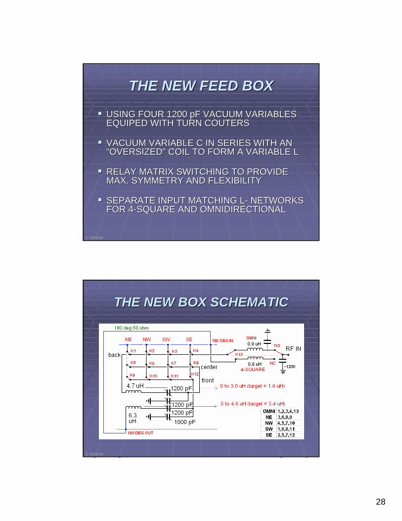
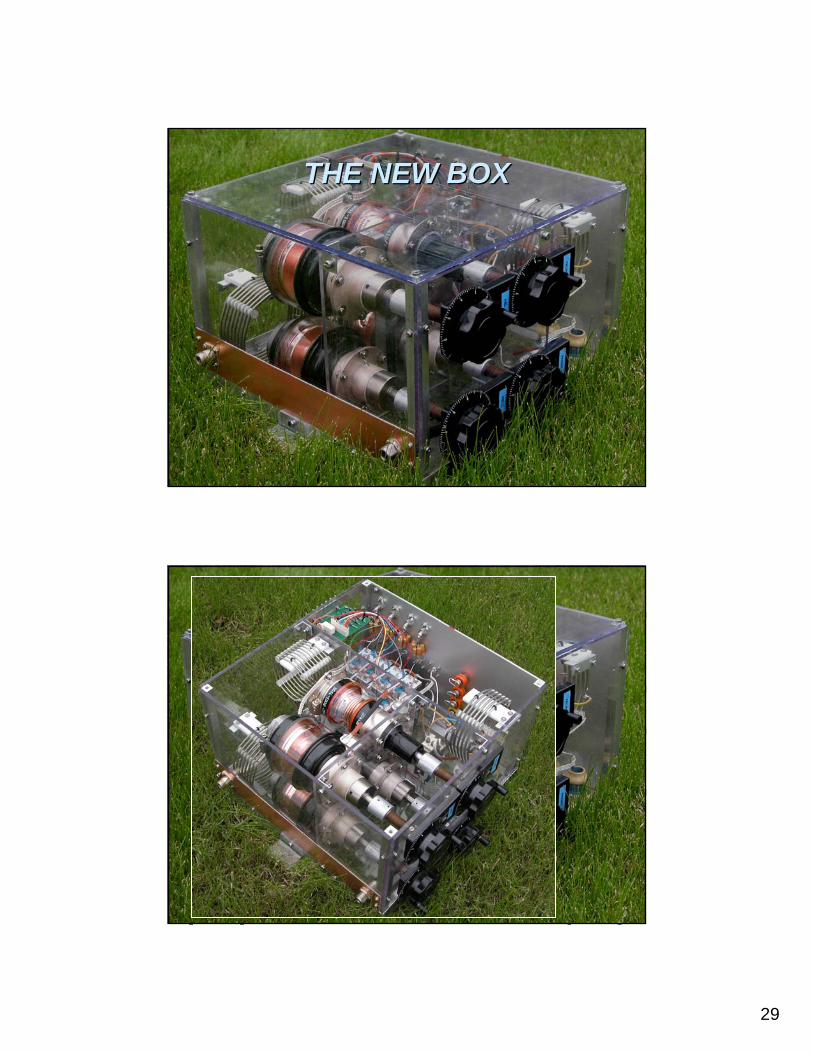
THE NEW FEED BOXTHE NEW FEED BOX
USING FOUR 1200 USING FOUR 1200 pFpF VACUUM VARIABLES VACUUM VARIABLES EQUIPED WITH TURN COUTERSEQUIPED WITH TURN COUTERS
VACUUM VARIABLE C IN SERIES WITH AN VACUUM VARIABLE C IN SERIES WITH AN ““OVERSIZEDOVERSIZED”” COIL TO FORM A VARIABLE LCOIL TO FORM A VARIABLE L
RELAY MATRIX SWITCHING TO PROVIDE RELAY MATRIX SWITCHING TO PROVIDE MAX. SYMMETRY AND FLEXIBILITYMAX. SYMMETRY AND FLEXIBILITY
SEPARATE INPUT MATCHING LSEPARATE INPUT MATCHING L-- NETWORKS NETWORKS FOR 4FOR 4--SQUARE AND OMNIDIRECTIONALSQUARE AND OMNIDIRECTIONAL
© ON4UN
THE NEW BOX SCHEMATICTHE NEW BOX SCHEMATIC
© ON4UN
29
THE NEW BOXTHE NEW BOX
THE NEW BOXTHE NEW BOX
30
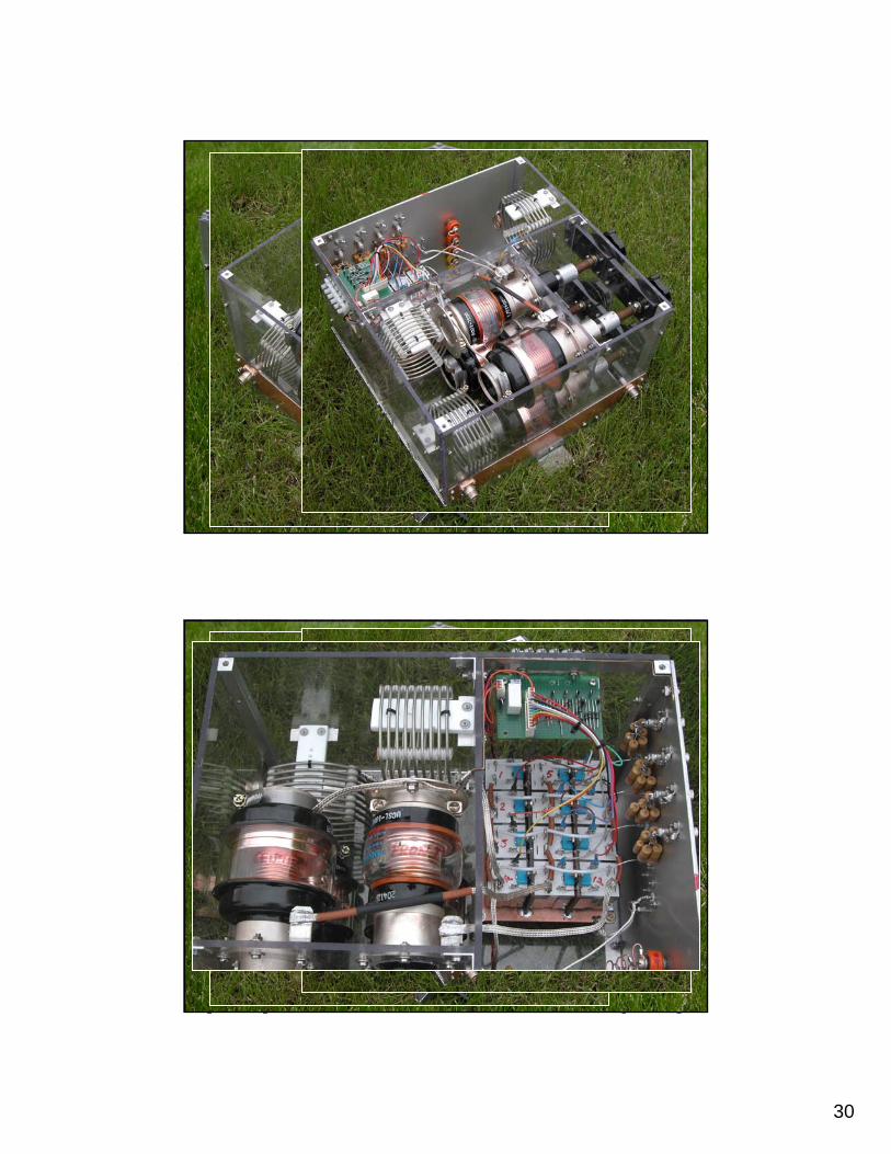
THE NEW BOXTHE NEW BOX
THE NEW BOXTHE NEW BOX
31
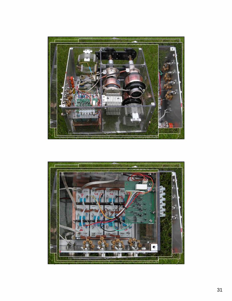
THE NEW BOXTHE NEW BOX
THE NEW BOXTHE NEW BOX
32
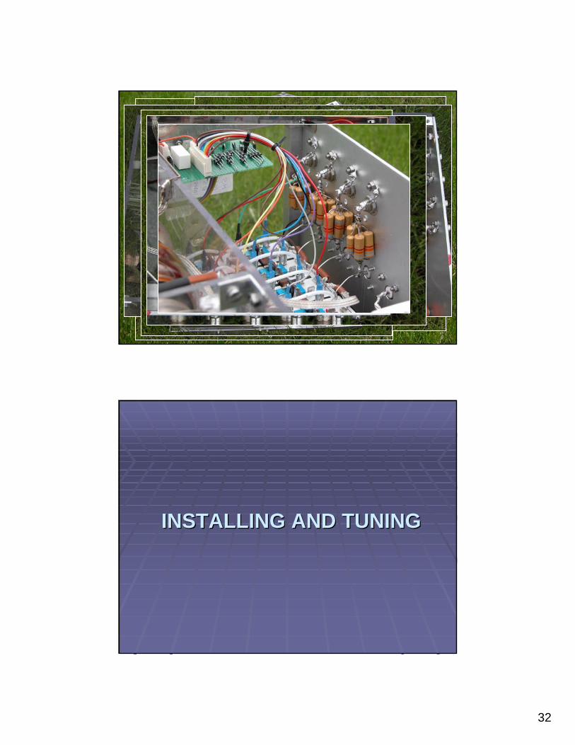
THE NEW BOXTHE NEW BOX
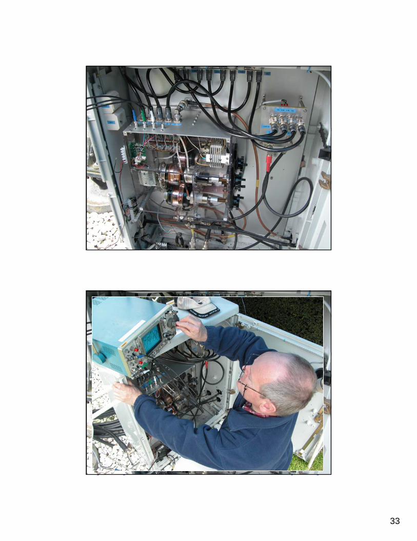
INSTALLING AND TUNINGINSTALLING AND TUNING
33
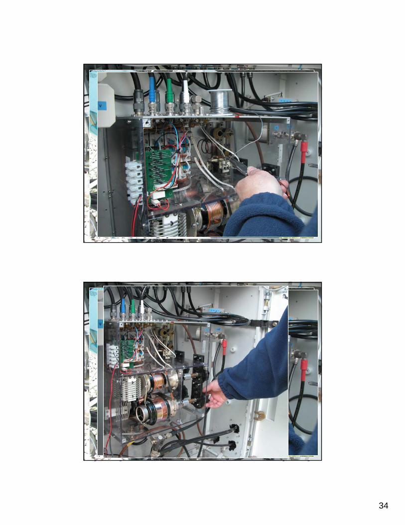
INSTALLING AND TUNINGINSTALLING AND TUNING
INSTALLING AND TUNINGINSTALLING AND TUNING
34
INSTALLING AND TUNINGINSTALLING AND TUNING
INSTALLING AND TUNINGINSTALLING AND TUNING
35
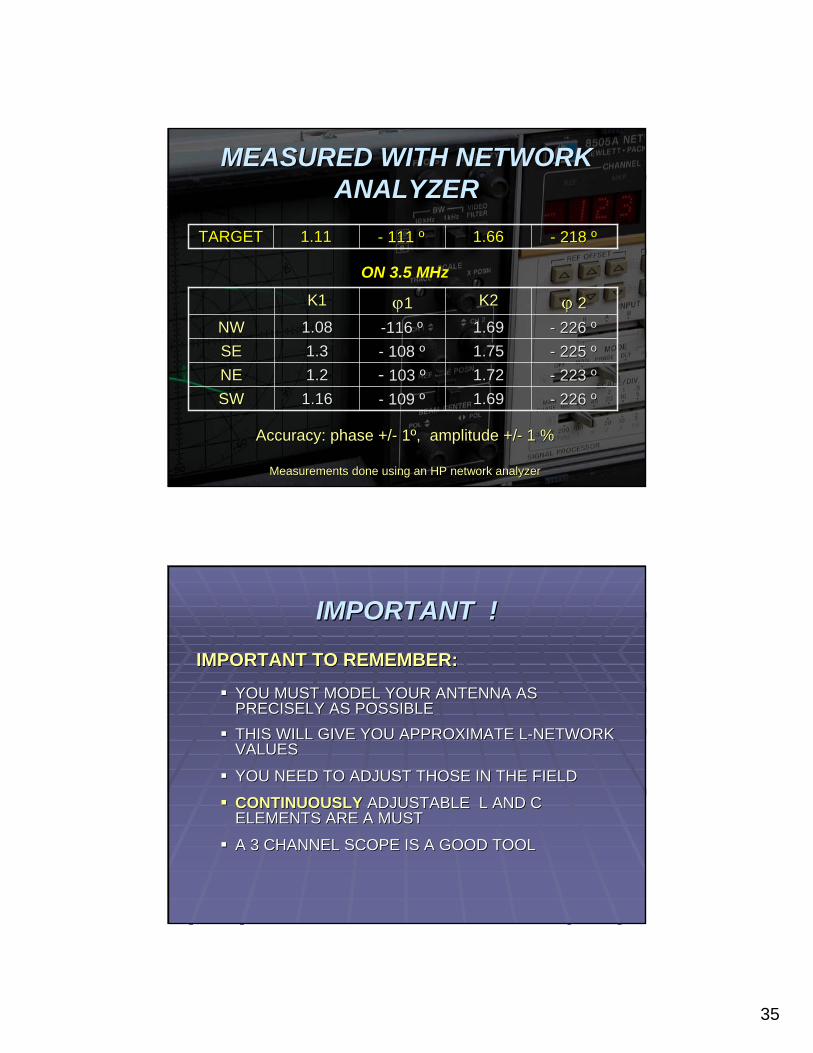
-- 226 226 ºº1.691.69-- 109 109 ºº1.161.16SWSW-- 223 223 ºº1.721.72-- 103 103 ºº1.21.2NENE-- 225 225 ºº1.75 1.75 -- 108 108 ºº1.31.3SESE-- 226 226 ºº1.69 1.69 --116 116 ºº1.08 1.08 NWNWϕϕ 22K2K2ϕϕ11K1K1
-- 218 218 ºº1.661.66-- 111 111 ºº1.111.11TARGETTARGET
Accuracy: phase +/Accuracy: phase +/-- 11ºº, amplitude +/, amplitude +/-- 1 %1 %
Measurements done using an HP network analyzer Measurements done using an HP network analyzer
MEASURED WITH NETWORK MEASURED WITH NETWORK ANALYZERANALYZER
ON 3.5 MHz
IMPORTANT TO REMEMBER:IMPORTANT TO REMEMBER:
YOU MUST MODEL YOUR ANTENNA AS YOU MUST MODEL YOUR ANTENNA AS PRECISELY AS POSSIBLEPRECISELY AS POSSIBLETHIS WILL GIVE YOU APPROXIMATE LTHIS WILL GIVE YOU APPROXIMATE L--NETWORK NETWORK VALUESVALUES
YOU NEED TO ADJUST THOSE IN THE FIELDYOU NEED TO ADJUST THOSE IN THE FIELD
CONTINUOUSLYCONTINUOUSLY ADJUSTABLE L AND C ADJUSTABLE L AND C ELEMENTS ARE A MUSTELEMENTS ARE A MUST
A 3 CHANNEL SCOPE IS A GOOD TOOLA 3 CHANNEL SCOPE IS A GOOD TOOL
IMPORTANT !IMPORTANT !

36
W1MK HYBRID ALIGNMENT SETUPW1MK HYBRID ALIGNMENT SETUP
This setup is used in conjunction with the W1MK detector / This setup is used in conjunction with the W1MK detector / power meterpower meter
A null method (bridge method)A null method (bridge method)Using a hybrid coupler networkUsing a hybrid coupler network
To NULL DETECTORTo NULL DETECTOR
FROM ELEMENT 1FROM ELEMENT 1
FROM ELEMENT 2FROM ELEMENT 2
© ON4UN
Already described in edition 3 of Low Band Already described in edition 3 of Low Band DxDx--ingingW1MK
37
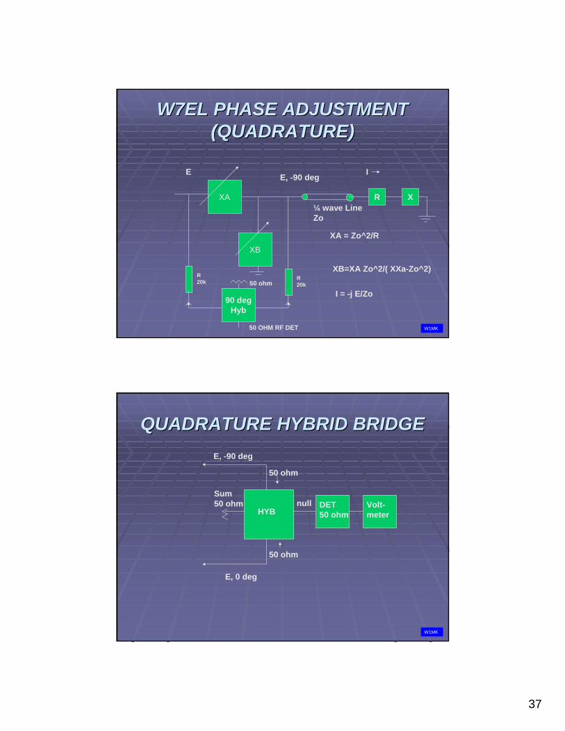
W7EL PHASE ADJUSTMENTW7EL PHASE ADJUSTMENT(QUADRATURE)(QUADRATURE)
XA
XB
E E, -90 deg
XA = Zo^2/R
XB=XA Zo^2/( XXa-Zo^2)
R X¼ wave LineZo
I
I = -j E/Zo
R20k
R20k
90 degHyb
50 OHM RF DET
50 ohm
W1MK
QUADRATURE HYBRID BRIDGEQUADRATURE HYBRID BRIDGEE, -90 deg
E, 0 deg
HYBDET50 ohm
Volt-meter
nullSum50 ohm
50 ohm
50 ohm
W1MK
38
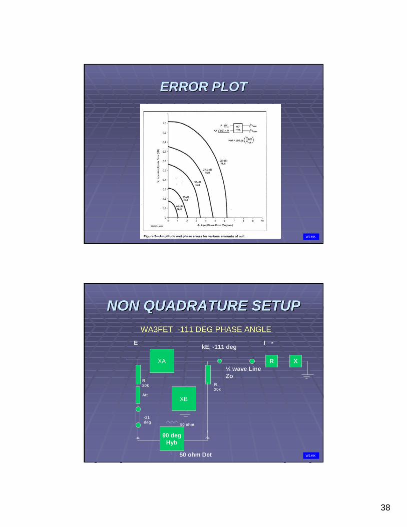
ERROR PLOTERROR PLOT
W1MK
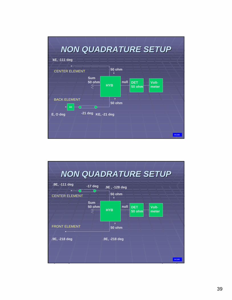
NON QUADRATURE SETUPNON QUADRATURE SETUP
XA
XB
E kE, -111 deg
R X¼ wave LineZo
I
R20k
Att
R20k
90 degHyb
50 ohm Det
-21deg 50 ohm
WA3FET -111 DEG PHASE ANGLE
W1MK
39
NON QUADRATURE SETUPNON QUADRATURE SETUPkE, -111 deg
HYBDET50 ohm
Volt-meter
nullSum50 ohm
50 ohm
50 ohmAtt
E, O deg KE, -21 deg-21 deg
CENTER ELEMENT
BACK ELEMENT
W1MK
NON QUADRATURE SETUPNON QUADRATURE SETUP.9E, -111 deg
HYBDET50 ohm
Volt-meter
nullSum50 ohm
50 ohm
50 ohm
.9E, -218 deg .9E, -218 deg
-17 deg .9E , -128 deg
CENTER ELEMENT
FRONT ELEMENT
W1MK
40
© ON4UN
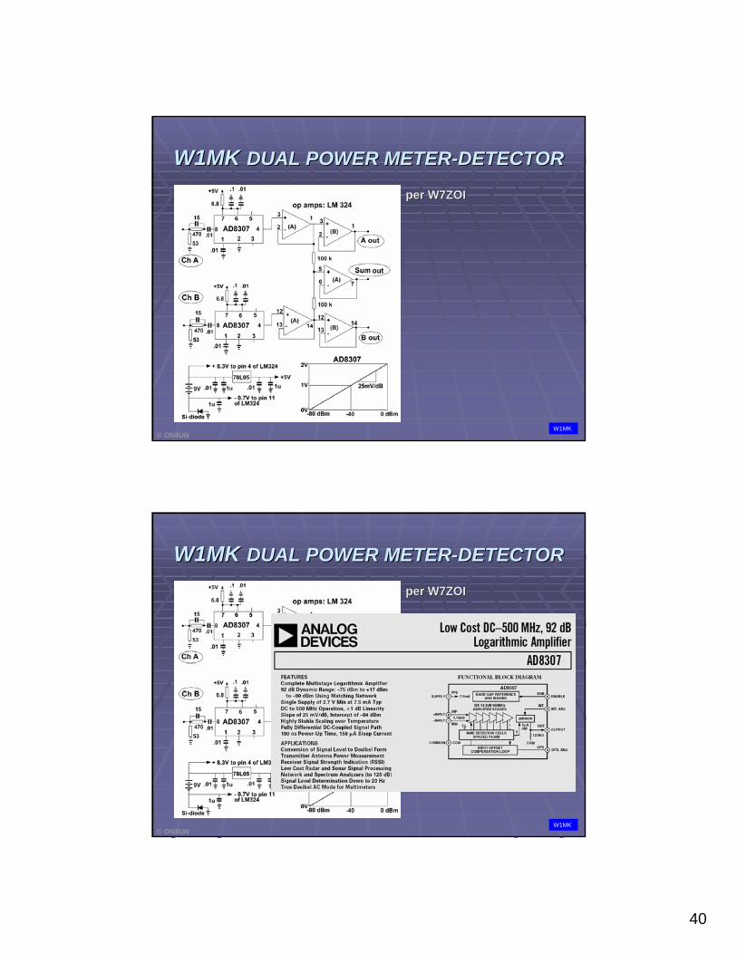
per W7ZOIper W7ZOI
W1MKW1MK DUAL POWER METERDUAL POWER METER--DETECTORDETECTOR
W1MK
© ON4UN
per W7ZOIper W7ZOI
W1MKW1MK DUAL POWER METERDUAL POWER METER--DETECTORDETECTOR
W1MK
41
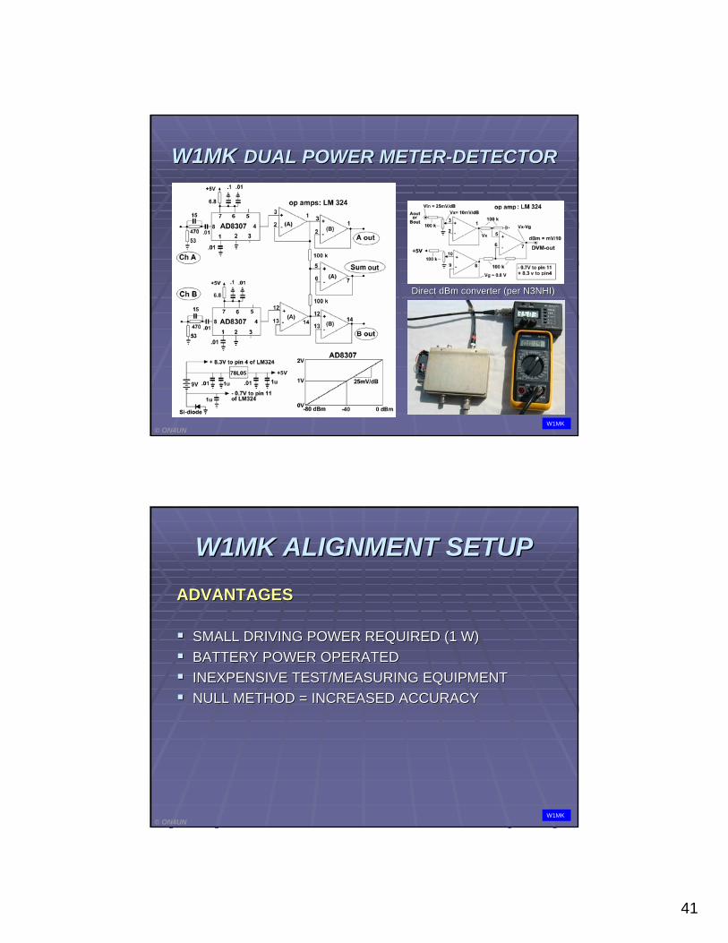
Direct dBm converter (per N3NHI)Direct dBm converter (per N3NHI)
© ON4UN
W1MKW1MK DUAL POWER METERDUAL POWER METER--DETECTORDETECTOR
W1MK
W1MK ALIGNMENT SETUPW1MK ALIGNMENT SETUPADVANTAGESADVANTAGES
SMALL DRIVING POWER REQUIRED SMALL DRIVING POWER REQUIRED (1 W)(1 W)BATTERY POWER OPERATEDBATTERY POWER OPERATEDINEXPENSIVE TEST/MEASURING EQUIPMENTINEXPENSIVE TEST/MEASURING EQUIPMENTNULL METHOD = INCREASED ACCURACYNULL METHOD = INCREASED ACCURACY
© ON4UNW1MK
42
W1MK ALIGNMENT SETUPW1MK ALIGNMENT SETUP
DRAWBACKSDRAWBACKS
VISUALLY VISUALLY ““LESS LESS INSTRUCTIVEINSTRUCTIVE””
CONCLUSIONCONCLUSION
SCOPE AND NULLSCOPE AND NULL--METHOD IN REALITY METHOD IN REALITY HAVE COMPARABLE ACCURACY HAVE COMPARABLE ACCURACY
© ON4UNW1MK
© ON4UN
43
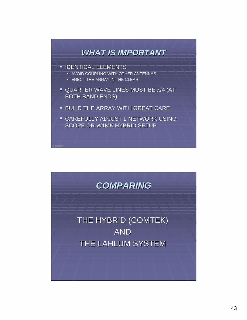
WHAT IS IMPORTANTWHAT IS IMPORTANTIDENTICAL ELEMENTSIDENTICAL ELEMENTS
AVOID COUPLING WITH OTHER ANTENNASAVOID COUPLING WITH OTHER ANTENNASERECT THE ARRAY IN THE CLEARERECT THE ARRAY IN THE CLEAR
QUARTER WAVE LINES MUST BE QUARTER WAVE LINES MUST BE λλ/4 (AT /4 (AT BOTH BAND ENDS)BOTH BAND ENDS)
BUILD THE ARRAY WITH GREAT CAREBUILD THE ARRAY WITH GREAT CARE
CAREFULLY ADJUST L NETWORK USING CAREFULLY ADJUST L NETWORK USING SCOPE OR W1MK HYBRID SETUPSCOPE OR W1MK HYBRID SETUP
© ON4UN
COMPARINGCOMPARING
THE HYBRID (COMTEK) THE HYBRID (COMTEK) AND AND
THE LAHLUM SYSTEMTHE LAHLUM SYSTEM
44
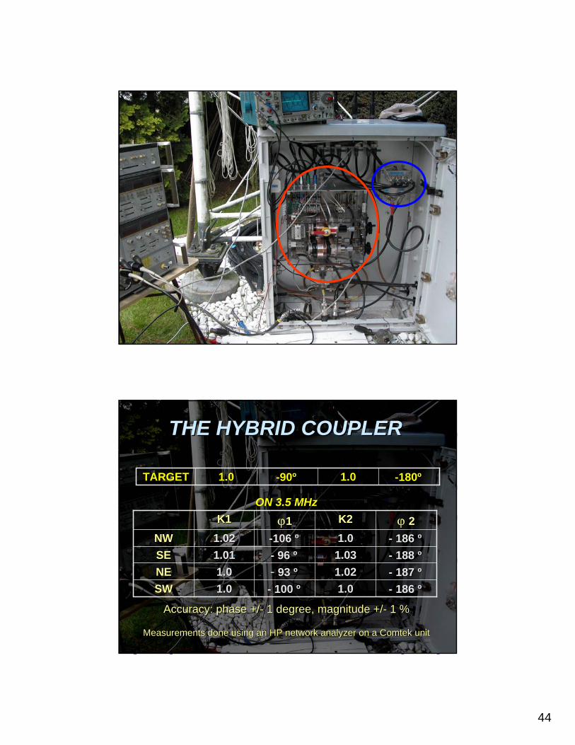
-- 186 186 ºº1.0 1.0 -- 100 100 ºº1.0 1.0 SWSW-- 187 187 ºº1.02 1.02 -- 93 93 ºº1.0 1.0 NENE-- 188 188 ºº1.03 1.03 -- 96 96 ºº1.01 1.01 SESE-- 186 186 ºº1.0 1.0 --106 106 ºº1.02 1.02 NWNWϕϕ 22K2K2ϕϕ11K1K1
--180180ºº1.01.0--9090ºº1.01.0TARGETTARGET
Accuracy: phase +/Accuracy: phase +/-- 1 degree, magnitude +/1 degree, magnitude +/-- 1 %1 %
Measurements done using an HP network analyzer on a Measurements done using an HP network analyzer on a ComtekComtek unitunit
THETHE HYBRID HYBRID COUPLERCOUPLER
ON 3.5 MHz
45
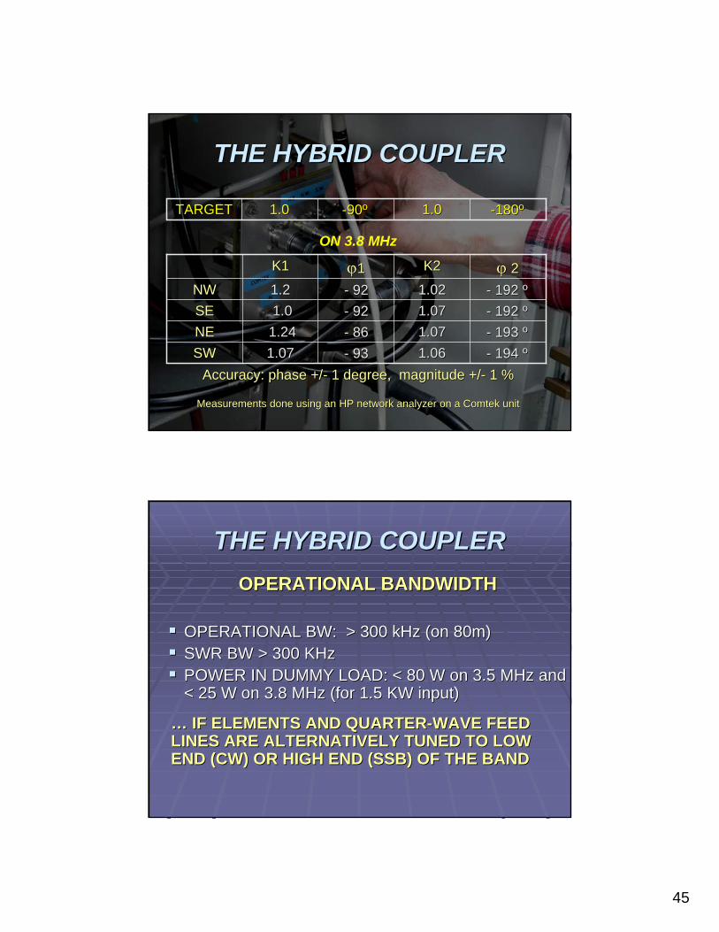
-- 194 194 ºº1.06 1.06 -- 93 93 1.07 1.07 SWSW-- 193 193 ºº1.07 1.07 -- 86 86 1.241.24NENE-- 192 192 ºº1.07 1.07 -- 92 92 1.01.0SESE-- 192 192 ºº1.02 1.02 -- 92 92 1.2 1.2 NWNWϕϕ 22K2K2ϕϕ11K1K1
--180180ºº1.01.0--9090ºº1.01.0TARGETTARGET
Accuracy: phase +/Accuracy: phase +/-- 1 degree, magnitude +/1 degree, magnitude +/-- 1 %1 %
Measurements done using an HP network analyzer on a Measurements done using an HP network analyzer on a ComtekComtek unitunit
THETHE HYBRID HYBRID COUPLERCOUPLER
ON 3.8 MHz
OPERATIONAL BANDWIDTHOPERATIONAL BANDWIDTH
OPERATIONAL BW: > 300 kHz (on 80m)OPERATIONAL BW: > 300 kHz (on 80m)SWR BW > 300 KHzSWR BW > 300 KHzPOWER IN DUMMY LOAD: < POWER IN DUMMY LOAD: < 8080 W on 3.5 MHz and W on 3.5 MHz and < 25 W on 3.8 MHz (for 1.5 KW input)< 25 W on 3.8 MHz (for 1.5 KW input)
THETHE HYBRID HYBRID COUPLERCOUPLER
…… IF ELEMENTS AND QUARTERIF ELEMENTS AND QUARTER--WAVE FEED WAVE FEED LINES ARE ALTERNATIVELY TUNED TO LOW LINES ARE ALTERNATIVELY TUNED TO LOW ENDEND (CW) OR HIGH END (SSB) OF THE BAND(CW) OR HIGH END (SSB) OF THE BAND
46
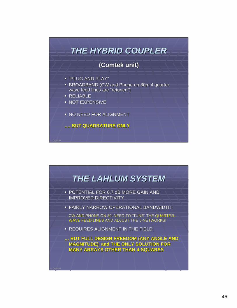
(Comtek unit)(Comtek unit)
““PLUG AND PLAYPLUG AND PLAY””BROADBAND (CW and Phone on 80m if quarter BROADBAND (CW and Phone on 80m if quarter wave feed lines are wave feed lines are ““retunedretuned””))RELIABLE RELIABLE NOT EXPENSIVENOT EXPENSIVE
NONO NEED FOR ALIGNMENTNEED FOR ALIGNMENT
……. BUT QUADRATURE ONLY. BUT QUADRATURE ONLY
© ON4UN
THETHE HYBRID HYBRID COUPLERCOUPLER
POTENTIAL FOR 0.7 dB MORE GAIN AND POTENTIAL FOR 0.7 dB MORE GAIN AND IMPROVED DIRECTIVITYIMPROVED DIRECTIVITY
FAIRLY NARROW OPERATIONAL BANDWIDTH:FAIRLY NARROW OPERATIONAL BANDWIDTH:
CW AND PHONE ON 80: NEED TO CW AND PHONE ON 80: NEED TO ““TUNETUNE”” THE THE QUARTERQUARTER--WAVE FEED LINESWAVE FEED LINES AND ADJUST THE LAND ADJUST THE L--NETWORKS!NETWORKS!
REQUIRES ALIGNMENT IN THE FIELDREQUIRES ALIGNMENT IN THE FIELD
…… BUT FULL DESIGN FREEDOM (ANY ANGLE AND BUT FULL DESIGN FREEDOM (ANY ANGLE AND MAGNITUDE) and THE ONLY SOLUTION FOR MAGNITUDE) and THE ONLY SOLUTION FOR MANY ARRAYS OTHER THAN 4MANY ARRAYS OTHER THAN 4--SQUARESSQUARES
© ON4UN
THE LAHLUM THE LAHLUM SYSTEMSYSTEM

47
WRAP UPWRAP UP
W1MK DEVELOPED THE MATHEMATICS GIVING FULL W1MK DEVELOPED THE MATHEMATICS GIVING FULL DESIGN FREEDOM (ANY MAGNITUDE/PHASE)DESIGN FREEDOM (ANY MAGNITUDE/PHASE)THE LAHLUM FEED SYSTEM WAS APPLIED TO ON4UNTHE LAHLUM FEED SYSTEM WAS APPLIED TO ON4UN’’S 4S 4--SQUARESQUARESUITABLE ALIGNMENT METHODS WERE DEVELOPED SUITABLE ALIGNMENT METHODS WERE DEVELOPED AND DOCUMENTEDAND DOCUMENTEDA NEW FULLY FLEXIBLE FEED BOX WAS DESIGNED AND A NEW FULLY FLEXIBLE FEED BOX WAS DESIGNED AND CONSTRUCTEDCONSTRUCTEDTESTING WAS DONE ON BOTH QUADRATURE (HYBRID) TESTING WAS DONE ON BOTH QUADRATURE (HYBRID) AND LAHLUM (OPTIMIZED AMP/PHASE) CONFIGURATIONAND LAHLUM (OPTIMIZED AMP/PHASE) CONFIGURATIONCONCLUSIONS WERE DRAWNCONCLUSIONS WERE DRAWN
© ON4UN
NEW FEED SYSTEM FOR ARRAYSNEW FEED SYSTEM FOR ARRAYS
NEW FEED SYSTEM FOR ARRAYSNEW FEED SYSTEM FOR ARRAYS
THANK YOU,..THANK YOU,..ROGER, ON6WUROGER, ON6WU
ANDANDROBYE, W1MKROBYE, W1MK
© ON4UN
48
By John Devoldere, ON4UNBy John Devoldere, ON4UNRobye Lahlum, W1MKRobye Lahlum, W1MK
Roger Vermet, ON6WURoger Vermet, ON6WU© ON4UN
NEW FEED SYSTEM FOR ARRAYSNEW FEED SYSTEM FOR ARRAYS