Embed Size (px)
Citation preview
EN - Instructions and warnings for installation and use
IT - Istruzioni ed avvertenze per l’installazione e l’uso
FR - Instructions et avertissements pour l’installation et l’utilisation
ES - Instrucciones y advertencias para la instalación y el uso
DE - Installierungs-und Gebrauchsanleitungen und Hinweise
PL -Instrukcjeiostrzeżeniadoinstalacjiiużytkowania
NL - Aanwijzingen en aanbevelingen voor installatie en gebruik
Swing gate opener
4024 Kit5024 Kit4000 Kit5000 KitWG3524HS
Nice


EN
English – 1
1 GENERAL SAFETY WARNINGS AND PRECAUTIONS
1.1 - Safety warnings• CAUTION! - This manual contains important instructions and warn-
ings for personal safety. Wrong installation can cause serious injuries. Be-fore starting work read all the manual carefully. If in doubt, stop installation and ask the Nice Assistance Department for clarifications.
• CAUTION! – According to the most recent European legislation, the realisation of an automatic door or gate must comply with the reg-ulations of Directive 98/37/CE (Machine Directive) and in particular, standards EN 12445; EN 12543; EN 12635 and EN 13214-1, which de-clare the presumed conformity of the automation. In consideration of this, all the installation, connection, inspection and maintenance op-erations of the product must be performed exclusively by a qualified and competent technician!
• CAUTION! – Important instructions: keep this manual for any possible future requirement for maintenance and disposal of the product.
1.2 - Warnings for installation• Before installing check if this product is suited to automating your gate or
door (see chapter 3 and “Technical features of the product”). If unsuitable, DO NOT proceed with the installation.
• Include a disconnection device in the power supply system with an opening distance between the contacts to permit full disconnection in the conditions dictated by the category of surcharge III.
• All the installation and maintenance operations must occur with the automation disconnected from the electrical power supply. If the dis-connection device of the power supply is not visible from the area where the automatism is located, before starting the work it is necessary to attach a sign with the text “CAUTION! MAINTENANCE IN PROGRESS” on the dis-connection device.
• During installation handle the automatism with care avoiding crushing, knocks, falls or contact with liquids of any kind. Do not place the product near sources of heat, or expose it to naked flames. All these activities can damage and cause malfunctions or dangerous situations. If this occurs, stop the installation immediately and contact the Nice Assistance Department.
• Do not make alterations to any part of the product. Operations which are not permitted will cause only malfunctions. The manufacturer declines any liability for damage caused by arbitrary alterations to the product.
• If the gate or the door to be automated is fitted with a pedestrian door it is necessary to include a control system in the installation to prevent the opera-tion of the motor when the pedestrian door is open.
• Check there are no trapping points towards fixed parts when the leaf of the gate is in the maximum Open position, if necessary protect these parts.
• The push button control on the wall must be positioned in sight of the auto-mation, away from the moving parts, at a minimum height of 1.5 m from the ground and it must not be accessible to the public.
• The product packaging material must be disposed of respecting the local regulations in force.
2 DESCRIPTION OF THE PRODUCT AND ENVISAGED USE
This product is intended to be used for automating swing gates or doors in an exclusively residential context. CAUTION! – Any other use different to that described and in ambient conditions different to those set out in this manual is to be considered improper and forbidden!
The product is an electromechanical gear motor, equipped with a 24 v continu-ous current or 230V (depending on the model) alternate current motor and an endless screw reduction gear.The gear motor is powered by the external control unit to which it is connected.In the event of a black out, it is possible to move the gate leaves by hand, un-blocking the gear motor manually.
Fig. 1 shows all the components provided in the package (according to the model chosen):
[a] - electromechanical gear motor[b] - front bracket (for fixing the gear motor to the gate leaf)[c] - rear bracket and plate (for fixing the gear motor to the wall)[d] - metal parts (screws, washers, etc.)[e] - keys to manually unlock the gear motor
3 INSTALLATION
3.1 - Checks before installationBefore installation, check the integrity of the components, suitability of the model chosen and suitability of the environment chosen for the installation.
IMPORTANT – The gear motor cannot automate a manual gate which does not have a safe and efficient mechanical structure. Furthermore, it cannot solve the faults caused by wrong installation or bad mainte-nance of the gate itself.
3.2 - Suitability of the gate to being automated and the surrounding environment
• Check the mechanical structure of the gate is suited to being automated and conforms to the national laws in force (if necessary make reference to the da-ta on the gate label).
• Moving the gate leaf manually in Open and Close position, check the move-ment occurs with equal and constant attrition at each point of the stroke (there must be no moments of greater effort).
• Check the gate leaf remains balanced, that it does not move if brought man-ually to any position and left stopped.
• Check the space around the gear motor allows to manually unblock the gate leaf, easily and safely.
• Check the surfaces chosen for installing the product are solid and can guar-antee stable fixing.
• Check the fixing zone of the gear motor is compatible with the size of the lat-ter, see fig. 2: the correct Opening movement of the gate and the force the motor exerts to perform it, depend on the position in which the rear fixing bracket is secured. Therefore, before installing it is necessary to make refer-ence to graph 2 to define the maximum Opening angle of the leaf and the force of the motor, suited to the individual system.
3.3 - Limits of use of the productBefore installing the product, check the gate leaf is the right size and weight and falls within the limits shown in graph 1.
3.4 - Preparing for installationFig. 3 shows an example of an automation system designed with Nice com-ponents. These components are positioned according to a typical and usual scheme.Making reference to fig. 3, decide the approximate position in which to install each component envisaged by the system and the most appropriate connec-tion diagram.
Useful components for producing a complete system (fig. 3):
A - Electromechanical gear motorsB - Couple of photocellsC - Couple of stop blocks (in Opening)D - Columns for photocellsE - Flashing signalling device with incorporated antennaF - Key selector switch or digital keypadG - Control unit
3.5 - Installation of fixing brackets and gear motor3.5.1 – Installation of rear fixing bracket
Calculate the position of the rear bracket using graph 2.This graph serves to establish dimensions A and B and the value of the maximum opening angle of the leaf. Important – The values of A and B must be similar to allow linear movement of the automation.
01. Measure dimension C (fig. 4) on the fixing side;02. On graph 2, identify dimension C found and trace a horizontal line that
ENGLISHInstructions translated from Italian

EN
2 – English
determines the value of dimension B (*) as shown in the example of fig. 5; the meeting point with line “r.i.l” (installation line recommended) deter-mines the value of the angle of maximum opening. From this point, trace a vertical line as shown in the example of fig. 5 to determine the value of di-mension A.
If the angle found does not correspond to the requirements, adapt dimen-sion A and if necessary dimension B, so they are similar.
03. Before being fixed to the wall the bracket must be sealed to the specific fixing plate (fig. 6); if necessary the bracket can be cut adapting values of dimensions A and B.
Note – The rear bracket provided with the gearmotor has a length of 150 mm; in the case of special applications or an outward opening gate (fig. 7) the bracket model PLA6 (optional accessory) may be used.
CAUTION! – Before securing the rear bracket, check the fixing zone of the front bracket is in a solid part of the leaf, as this bracket must be fixed at a different height of the rear bracket (fig. 8).
04. At this point, fix the bracket using dowels, screws and washers required (not supplied).
3.5.2 – Installation of front fixing bracket
The front bracket must be fixed to the gate leaf respecting the values of dimen-sions D and E (Fig. 4).
Note – The front bracket provided with the gearmotor must be welded directly onto the gate leaf. If this is not possible, use the bracket model PLA8 (optional accessory)
01. Establish the value of dimension E using Table 1;02. Establish the height in which to position the front bracket, referring to fig. 8;03. Fix the bracket to the solid part of the gate leaf.
TABLE 1Model:
WG4024 - WG4000 -WG4000/V1
Model:WG5024 - WG5000 -
WG5000/V1 - WG3524HS
D (mm): 700 850
A (mm) E (mm)
100 600 750110 590 740120 580 730130 570 720140 560 710150 550 700160 540 690170 530 680180 520 670190 510 660200 500 650210 490 640220 480 630230 470 620240 610250 600260 590270 580280 570
3.5.3 – Installation of the gear motor on the fixing brackets
• Installing the gear motor on the rear bracket:
01. Fix the gear motor to the bracket as shown in fig. 9 using the screw, washer and nut supplied;
02. Tighten the nut to the end and then loosen by 1/10 of a turn to allow mini-mum clearance between the parts.
• Installing the gear motor on the front bracket:
01. Fix the gear motor to the bracket as shown in fig. 10 using the screw, washer and nut supplied;
02. Tighten the screw to the end. 03. Fix the label provided in the package, dealing with the unblocking and
blocking operations of the gear motor, permanently close to the gear motor.
3.6 - Setting the mechanical limit switchThe mechanical limit switch allows to set the stop position of the gate leaf, in this way, it is not necessary to use the stop blocks and the leaf does not hit against these at the end of the manoeuvre.
WARNING – In the event of applications with a gate equipped with opening towards the outside (fig. 7) it is necessary to invert the power supply wires. Set the limit switch in Opening of the gear motor as follows:
01. Unblock the gear motor as shown in fig. 14;02. Loosen the mechanical stop screw;03. Bring the gate leaf manually to the Open position required;04. Then, bring the mechanical stop to the end of the pin and block the screw
(fig. 11).05. Bring the leaf manually to the Close position and block the gear motor.
4 ELECTRICAL CONNECTIONS
CAUTION!
– A wrong connection can cause faults or danger; therefore follow scrupulously the connections set out.
– Perform the connection operations when the electricity is off.
To connect the gear motor to the control unit, proceed as follows:
01. Remove the lid of the gear motor as shown in fig. 12;02. Slacken the gearmotor cable clamp, thread the connecting cable through
the hole and connect the three electric wires as shown in fig. 13;03. Replace lid on gear motor.
To check the connections, direction of rotation of the motor, phase shift in the movement of the leaves and setting the limit switch, refer to the instructions manual of the control unit.
IMPORTANT – With a gate configured with opening towards the outside invert the power supply wires with respect to the standard installation.
5 INSPECTING THE AUTOMATION
This is the most important phase in realising the automation to guarantee maxi-mum safety. The inspection can be used also to periodically check the devices which make up the automatism.The inspection of the entire system must be performed by expert and qualified staff who must take responsibility of the tests requested, depending on the risk involved and to check compliance of what is set out by laws, rules and regulations and in particular all the requirements of regulation EN 12445 which establishes the testing methods to verify gate automatisms.
InspectionEach single component of the automatism, for example sensitive edges, pho-tocells, emergency shutdowns, etc. requires a specific inspection phase; for these devices follow the procedures shown in the respective instruction manu-als. For inspection of the gear motor follow the operations below:
01. Check that everything in this manual and in particular in chapter 1 has been rigorously complied with;
02. Unblock the gear motor as shown in fig. 14;03. Check it is possible to manually move the leaf when opening and closing
with a force no greater than 390N (approx. 40 kg);04. Block the gear motor and connect the electrical power supply;05. Using the control or shutdown devices envisaged (key selector switch,
control buttons or radio transmitters), perform a number of opening, clos-ing and stopping tests of the gate and check it behaves as it should;
06. Check the correct operation of all the safety devices one by one in the sys-tem (photocells, sensitive edges, emergency shutdown, etc.) and check the gate behaves as it should;
07. Command a closing manoeuvre and check the force of the impact of the leaf against the end of the mechanical limit switch. If necessary, try to un-load the pressure, finding a setting which gives better results;
08. If the dangerous situations caused by the movement of the leaf have been protected by limiting the force of impact the force must be measured as re-quired by regulation EN 12445;
Note – The gear motor is not provided with torque setting devices, such regu-lations are done by the Control unit.
Putting into operationThis can occur only after having performed, with positive results, all the inspec-tion phases of the gear motor and other devices present. To put it into opera-tion refer to the instructions manual of the control unit.
IMPORTANT – It is forbidden to put into partial or provisional operation.

EN
English – 3
6 PRODUCT MAINTENANCE
To keep the level of safety consistent and to guarantee maximum life of the en-tire automation it is necessary to maintain it regularly.The maintenance must be performed in line with the safety instructions of this manual and according to what is set out by the laws and regulations in force. For the gear motor a programmed maintenance within no more than 6 months is required.
Maintenance operations:
01. Disconnect any sources of electricity.02. Check the status of deterioration of all the materials which make up the
automation with particular attention to signs of erosion or oxidation of the structural parts: replace the parts which do not provide sufficient guarantees.
03. Check the screw connections are sufficiently tight.04. Check the bolt and endless screw are suitably greased.05. Check the wear of the moving parts and, if necessary, replace used parts.06. Reconnect the sources of electrical power and perform all the tests and
checks envisaged in chapter 5.For the other devices present in the system refer to the individual instruction manuals.
DISPOSAL OF THE PRODUCT
This product is an integral part of the automation, and therefore, they must be disposed of together.
As for the installation operations, at the end of the life of this product, the dis-mantling operations must be performed by qualified personnel.
This product is made from different types of materials: some can be recycled, others must be disposed of. Please inform yourselves on the recycling or dis-posal systems provided for by the laws in force in your area, for this category of product.
CAUTION! – some parts of the product can contain polluting or dangerous substances which, if dispersed in the environment, may cause serious harm to the environment and human health.
As indicated by the symbol at the side, it is forbidden to throw this product into domestic refuse. Therefore, follow the “separat-ed collection” instructions for disposal, according to the meth-ods provided for by local regulations in force, or redeliver the product to the retailer at the moment of purchase of a new, equivalent product.
CAUTION! – the regulations in force at local level may envisage heavy sanc-tions in case of abusive disposal of this product.
Durability of the product
Durability is the average economic life of the product. The value of durability is strongly influenced by the demand index of the manoeuvres performed by the automatism: that is the sum of all the factors which contribute to the wear of the product (see Table 2).
To establish the probable durability of your automatism proceed as follows:
01. Calculate the demand index summing the values in percentage of the en-tries present in Table 2 to each other;
02. In Graph A, from the value just found, trace a vertical line until you inter-sect the curve; from this point trace a horizontal line to cross the line of “cy-cles of manoeuvres”. The value established is the estimated durability of your product.
The estimate of durability is performed on the basis of the design calculations and the results of tests carried out on prototypes. In fact, being an estimate, it does not give any guarantee on the actual duration of the product.
TABLE 2Demand index
WG4024WG4000
WG4000/V1
WG5024WG5000
WG5000/V1WG3524HS
Leaf weight:
> 100 kg 10 % 0 % 10 %> 200 kg 20 % 10 % 20 %> 300 kg 30 % 20 % –––> 400 kg ––– 30 % –––
Leaf length:1 - 2 m 20 % 0 % 10 %2 - 3 m ––– 10 % 20 %
3 - 3,5 m ––– 20 % –––Operating temperature: 20 % 20 % 20 %Blind leaf: 15 % 15 % 15 %Installation in windy area: 15 % 15 % 15 %
0
0
25.000
50.000
75.000
100.000
125.000
10 20 30 40 50 60 70 80 90 100
GRAPH A
Demand index (%)
cycl
es o
f m
ano
euvr
es
Example of calculation of durability of a Wingo WG5024 gear motor (re-fer to Table 2 and Graph A):
- leaf weight = 200 kg (demand index= 10%)- leaf length = 2.5 m (demand index = 20%)- no other stress elements presentTotal demand index = 20%
Durability estimate = 80.000 cycles of manoeuvre

EN
4 – English
CE declaration of conformity and declaration of incorporation for a “quasi-machine”
Declaration in accordance with Directives: 2004/108/EC (EMC); 2006/42/EC (MD) annex II, part B
Note - The content of this declaration corresponds to the declaration made in the official document filed in the offices of Nice S.p.a., and particularly the latest version thereof available prior to the printing of this manual. The text contained here has been adapted to meet editorial requirements. A copy of the original declaration may be requested from Nice S.p.a. (TV) I.
Declaration number: 143/WINGO Revision: 9 Language: EN
Name of manufacturer: NICE S.p.A.Address: Via Pezza Alta N°13, 31046 Rustignè di Oderzo (TV) Italy.Person authorized to provide technical documentation: NICE S.p.A. – Via Pezza Alta N°13, 31046 Rustignè di Oderzo (TV) Italy.Product type: Electric gearmotor for swing gates.Model / Type : WG4000, WG4000/V1, WG5000, WG5000/V1, WG4024, WG5024, WG3524HSAccessories: No accessory.
The undersigned Mauro Sordini, as Chief Executive Officer, hereby declares under his own responsibility that the products identified above comply with the provisions of the following directives:• DIRECTIVE 2004/108/EC OF THE EUROPEAN PARLIAMENT AND COUNCIL of December 15 2004 concerning alignment of Member States’ legislation
regarding electromagnetic compatibility and abrogating directive 89/336/EEC, according to the following harmonized standards: EN 61000-6-2:2005; EN 61000-6-3:2007 + A1:2011.
The product also complies with the following directive in accordance with the requirements for “quasi-machines”:• Directive 2006/42/EC OF THE EUROPEAN PARLIAMENT AND COUNCIL of May 17 2006 regarding machines and amending directive 95/16/EC (con-
solidated text).– I declare that the pertinent technical documentation has been prepared in accordance with Annex VII B to Directive 2006/42/EC and that the following
essential requirements have been met: 1.1.1 - 1.1.2 - 1.1.3 - 1.2.1 -1.2.6 - 1.5.1 -1.5.2 - 1.5.5 - 1.5.6 - 1.5.7 - 1.5.8 - 1.5.10 - 1.5.11.– The manufacturer agrees to send the national authorities pertinent information on the “quasi-machine” in response to a motivated request without affect-
ing its intellectual property rights. – If the “quasi-machine” is operated in a European country with an official language other than the language used in this declaration, the importer must as-
sociate a translation with this declaration.– The “quasi-machine” must not be operated until the final machine in which it is to be incorporated is declared to conform to the provisions of Directive
2006/42/EC, if applicable to it.
The product also complies with the following standards: EN 60335-1:2002 + A1:2004 + A11:2004 + A12:2006 + A2:2006 + A13:2008 + A14:2010 + A15:2011; EN 60335-2-103:2003 + A11:2009.
The parts of the product which are subject to the following standards comply with them: EN 13241-1:2003 + A1:2011; EN 12445:2002; EN 12453:2002; EN 12978:2003 + A1:2009.
Oderzo, 30 April 2015Eng. Mauro Sordini
(Chief Executive Officer)
CAUTIONS: • The technical features set out refer to an ambient temperature of 20°C (± 5°C). • Nice S.p.a. reserves the right to make alterations to the product any time it deems it necessary, keeping the same functionality and destination of use.
WG4024 WG5024 WG4000 WG4000/V1 WG5000 WG5000/V1 WG3524HSType electromechanical gear motor for gates or doors with leaf openingPower input 24 V 24 V 230 V~ 50 Hz 120 V~ 60 Hz 230 V~ 50 Hz 120 V~ 60 Hz 24 VMaximum absorption 3,5 A 3,5 A 1,5 A 1,5 A 1,5 A 2,5 A 5 ANominal absorption 2 A 2 A 0,5 A 0,5 A 0,5 A 1 A 3 AMaximum absorbed power 85 W 85 W 200 W 200 W 200 W 200 W 120 WNominal absorbed power 50 W 50 W 130 W 130 W 130 W 130 W 72 WProtection grade IP 44 IP 44 IP 44 IP 44 IP 44 IP 44 IP 44Travel 320 mm 470 mm 320 mm 320 mm 470 mm 470 mm 470 MMSpeed loadless 0,018 m/s 0,016 m/s 0,016 m/s 0,020 m/s 0,013 m/s 0,016 m/s 0,040 m/sMaximum thrust 1500 N 1500 N 1500 N 1500 N 1700 N 1700 N 1500 NNominal thrust 500 N 500 N 500 N 500 N 600 N 600 N 650 NOperating temperature -20 °C to +50 °CCycles h at nominal torque 40 40 30 30 30 30 30Durability estimated between 80,000 and 250,000 cycles of manoeuvres according to the conditions set out in Table 2Insulation class A A F F F F FDimensions (mm) 770 x 98 x 95 h 920 x 98 x 95 h 770 x 98 x 95 h 770 x 98 x 95 h 920 x 98 x 95 h 920 x 98 x 95 h 920 x 98 x 95 hWeight (kg) 6 6 6 6 6 6 6
TECHNICAL FEATURES OF THE PRODUCT

IT
Italiano – 1
1 AVVERTENZE E PRECAUZIONI GE NERALIPER LA SICUREZZA
1.1 - Avvertenze per la sicurezza• ATTENZIONE! – Il presente manuale contiene importanti istruzioni e
avvertenze per la sicurezza delle persone. Un’installazione errata può causare gravi ferite. Prima di iniziare il lavoro è necessario leggere attenta-mente tutte le parti del manuale. In caso di dubbi, sospendere l’installazione e richiedere chiarimenti al Servizio Assistenza Nice.
• ATTENZIONE! – Secondo la più recente legislazione europea, la rea-lizzazione di una porta o di un cancello automatico deve rispettare le norme previste dalla Direttiva 98/37/CE (Direttiva Macchine) e in par-ticolare, le norme EN 12445; EN 12453; EN 12635 e EN 13241-1, che consentono di dichiarare la presunta conformità dell’automazione. In considerazione di ciò, tutte le operazioni di installazione, di collega-mento, di col laudo e di manutenzione del prodotto devono es sere ef-fettuate es clusivamente da un tecnico qualificato e competente!
• ATTENZIONE! – Istruzioni importanti: conservare questo manuale per eventuali interventi futuri di manutenzione e di smaltimento del pro-dotto.
1.2 - Avvertenze per l’installazione• Prima di iniziare l’installazione verificare se il presente prodotto è adatto ad
automatizzare il vostro cancello o portone (vedere capitolo 3 e le “Caratteristi-che tecniche del prodotto”). Se non è adatto, NON procedere all’istallazione.
• Prevedere nella rete di alimentazione dell’impianto un dispositivo di discon-nessione con una distanza di apertura dei contatti che consenta la disconnes-sione completa nelle condizioni dettate dalla categoria di sovratensione III.
• Tutte le operazioni di installazione e di manutenzione devono avveni-re con l’automazione scollegata dall’alimentazione elettrica. Se il di-spositivo di sconnessione dell’alimentazione non è visibile dal luogo dove è posizionato l’automatismo, prima di iniziare il lavoro è necessario attaccare sul dispositivo di sconnessione un cartello con la scritta “ATTENZIONE! MA-NUTENZIONE IN CORSO”.
• Durante l’installazione maneggiare con cura l’automatismo evitando schiac-ciamenti, urti, cadute o contatto con liquidi di qualsiasi natura. Non mettere il prodotto vicino a fonti di calore, né esporlo a fiamme libere. Tutte queste azioni possono danneggiarlo ed essere causa di malfunzionamenti o situazio-ni di pericolo. Se questo accade, sospendere immediatamente l’installazione e rivolgersi al Servizio Assistenza Nice.
• Non eseguire modifiche su nessuna parte del prodotto. Operazioni non per-messe possono causare solo malfunzionamenti. Il costruttore declina ogni responsabilità per danni derivanti da modifiche arbitrarie al prodotto.
• Se il cancello o il portone da automatizzare è dotato di una porta pedonale occorre predisporre l’impianto con un sistema di controllo che inibisca il fun-zionamento del motore quando la porta pedonale è aperta.
• Verificare che non vi siano punti d’intrappolamento verso parti fisse quando l’anta del cancello si trova nella posizione di massima Apertura; eventualmen-te proteggere tali parti.
• La pulsantiera di comando a parete deve essere posizionata in vista dell’au-tomazione, lontano dalle sue parti in movimento, ad un’altezza minima di 1,5 m da terra e non accessibile al pubblico.
• Il materiale dell’imballo del prodotto deve essere smaltito nel pieno rispetto della normativa locale.
2 DESCRIZIONE DEL PRODOTTO EDESTINAZIONE D’USO
Il presente prodotto è destinato ad essere utilizzato per automatizzare cancelli o portoni ad ante battenti, in ambito esclusivamente residenziale. ATTENZIO-NE! – Qualsiasi altro uso diverso da quello descritto e in condizioni am-bientali diverse da quelle riportate in questo manuale è da considerarsi improprio e vietato!
Il prodotto è un motoriduttore elettromeccanico, provvisto di un motore in cor-rente continua a 24 V o in corrente alternata a 230 V (secondo il modello scelto)
e di un riduttore con vite senza fine.Il motoriduttore viene alimentato dalla Centrale di comando esterna a cui deve essere collegato.In caso d’interruzione dell’energia elettrica (black-out), è possibile muovere ‘a mano’ le ante del cancello sbloccando ma nualmente il motoriduttore.
La fig. 1 mostra tutti i componenti presenti nella confezione (secondo il mo-dello scelto):
[a] - motoriduttore elettromeccanico[b] - staffa anteriore (per fissaggio del motoriduttore all’anta del cancello)[c] - staffa posteriore e piastra (per fissaggio del motoriduttore al muro)[d] - minuteria metallica (viti, rondelle, ecc.)[e] - chiavi per lo sblocco manuale del motoriduttore
3 INSTALLAZIONE
3.1 - Verifiche preliminari all’installazionePrima di procedere all’installazione, è necessario verificare l’integrità dei com-ponenti del prodotto, l’adeguatezza del modello scelto e l’idoneità dell’ambien-te destinato all’installazione.
IMPORTANTE – Il motoriduttore non può automatizzare un cancel-lo ma nuale che non abbia una struttura meccanica efficiente e sicura. Inoltre, non può risolvere i difetti causati da una sbagliata installazione o da una cattiva manutenzione del cancello stesso.
3.2 - Idoneità del cancello da automatizzare e dell’ambiente circostante
• Verificare che la struttura meccanica del cancello sia adatta ad essere auto-matizzata e conforme alle norme vigenti sul territorio (eventualmente fare rife-rimanto ai dati riportati sull’etichetta del cancello).
• Muovendo manualmente l’anta del cancello in Apertura e in Chiusura, veri-ficare che il movimento avvenga con attrito uguale e costante in ogni punto della corsa (non devono esserci momenti di maggiore sforzo).
• Verificare che l’anta del cancello resti in equilibrio, cioè che non si muova se portata manualmente in una qualsiasi posizione e lasciata ferma.
• Verificare che lo spazio intorno al motoriduttore consenta di sbloccare ma-nualmente le ante del cancello, in modo facile e sicuro.
• Verificare che le superfici scelte per l’installazione del prodotto siano solide e possano garantire un fissaggio stabile.
• Verificare che la zona di fissaggio del motoriduttore sia compatibile con l’in-gombro di quest’ultimo, vedere fig. 2: il corretto movimento di Apertura del cancello e la forza che il motore esercita per eseguirlo, dipendono dalla posi-zione nella quale viene fissata la staffa di fissaggio posteriore. Quindi, prima di procedere all’installazione è necessario fare riferimento al grafico 2 per de-finire l’angolo di Apertura massima dell’anta e la forza del motore, adatta al proprio impianto.
3.3 - Limiti d’impiego del prodottoPrima di eseguire l’installazione del prodotto, verificare che l’anta del cancello abbia dimensioni e peso rientranti nei limiti riportati nel grafico 1.
3.4 - Lavori di predisposizione all’installazioneLa fig. 3 mostra un esempio di impianto di automatizzazione realizzato con componenti Nice. Questi componenti sono posizionati se condo uno schema tipico ed usuale.Facendo riferimento alla fig. 3, stabilire la posizione approssimativa in cui verrà installato ciascun componente previsto nell’impianto e, lo schema di collega-mento più appropriato.
Componenti utili per realizzare un impianto completo (fig. 3):
A - Motoriduttori elettromeccaniciB - Coppia di fotocelluleC - Coppia di fermi di arresto (in Apertura)D - Colonne per fotocelluleE - Segnalatore lampeggiante con antenna incorporataF - Selettore a chiave o tastiera digitaleG - Centrale di comando
3.5 - Installazione delle staffe di fissaggio e del motoriduttore
3.5.1 – Installazione della staffa di fissaggio posteriore
Calcolare la posizione della staffa posteriore utilizzando il Grafico 2.Questo grafico serve per determinare le quote A e B e il valore dell’angolo di
Istruzioni originali e complete
ITALIANO

IT
2 – Italiano
nella confezione, riguardante le operazioni di sblocco e blocco manuale del motoriduttore.
3.6 - Regolazione del finecorsa meccanicoIl finecorsa meccanico, permette di regolare la posizione di arresto dell’anta del cancello; in questo modo, non è necessario utilizzare i fermi d’arresto e si evita che l’anta alla fine della manovra sbatta su quest’ultimi.
ATTENZIONE – Nel caso di applicazioni con un cancello dotato di aper-tura verso l’esterno (fig. 7) è necessario invertire i fili di alimentazione. Regolare il finecorsa in Apertura del motoriduttore nel modo seguente:
01. Sbloccare il motoriduttore come mostrato nella fig. 14;02. Allentare la vite del fermo meccanico;03. Portare manualmente l’anta del cancello nella posizione desiderata in
Apertura;04. Quindi, portare il fermo meccanico in battuta del perno e bloccare la vite
(fig. 11);05. Portare manualmente l’anta nella posizione di Chiusura e bloccare il moto-
riduttore.
4 COLLEGAMENTI ELETTRICI
ATTENZIONE!
– Un collegamento errato può provocare guasti o si tuazioni di pericolo; quindi, rispettare scrupolosamente i collegamenti indicati.
– Eseguire le operazioni di collegamento con l’alimentazione elettrica scollegata.
Per collegare il motoriduttore alla Centrale di comando, procedere nel modo seguente:
01. Togliere il coperchio al motoriduttore come mostrato in fig. 12;02. Allentare il passacavo del motoriduttore, inserire nel suo foro il cavo di col-
legamento e collegare i tre fili elettrici come mostrato in fig. 13;03. Rimettere il coperchio al motoriduttore.
Per eseguire le verifiche dei collegamenti, del senso di rotazione del motore, dello sfasamento del movimento delle ante e della regolazione del finecorsa, fa-re riferimento al manuale istruzioni della Centrale di comando.
IMPORTANTE – In presenza di un cancello configurato con apertura verso l’esterno è necessario invertire i fili di alimentazione rispetto all’installazione standard.
5 COLLAUDO DELL’AUTOMAZIONE
Questa è la fase più importante nella realizzazione dell’automazione al fine di garantire la massima sicurezza. Il collaudo può essere usato anche come verifi-ca periodica dei dispositivi che compongono l’automatismo.Il collaudo dell’intero impianto deve essere eseguito da personale esperto e qualificato che deve farsi carico delle prove richieste, in funzione del rischio presente e di verificare il rispetto di quanto previsto da leggi, norma-tive e regolamenti, ed in particolare tutti i requisiti della norma EN12445 che stabilisce i metodi di prova per la verifica degli automatismi per cancelli.
CollaudoOgni singolo componente dell’automatismo, ad esempio bordi sensibili, foto-cellule, arresto di emergenza, ecc. richiede una specifica fase di collaudo; per questi dispositivi si dovranno eseguire le procedure riportate nei rispettivi ma-nuali istruzioni. Per il collaudo del motoriduttore eseguire le seguenti operazioni:
01. Verificare che sia stato rispettato rigorosamente tutto quanto previsto nel presente manuale ed in particolare nel capitolo 1;
02. Sbloccare il motoriduttore come mostrato nella fig. 14;03. Verificare che sia possibile muovere manualmente l’anta in apertura e in
chiusura con una forza non superiore a 390 N (circa 40 kg);04. Bloccare il motoriduttore e collegare l’alimentazione elettrica;05. Utilizzando i dispositivi di comando o arresto previsti (selettore a chiave,
pulsanti di comando o trasmettitori radio), effettuare delle prove di apertu-ra, chiusura ed arresto del cancello e verificare che il comportamento cor-risponda a quanto previsto;
06. Verificare uno ad uno il corretto funzionamento di tutti i dispositivi di sicu-rezza presenti nell’impianto (fotocellule, bordi sensibili, arresto di emergen-za, ecc.); e, verificare che il comportamento del cancello corrisponda a quanto previsto;
apertura massima dell’anta. Importante – I valori di A e B devono esse-re simili tra loro per consentire un movimento lineare dell’automazione.
01. Misurare sulla parete di fissaggio il valore della quota C (fig. 4);02. Sul grafico 2, individuare la quota C trovata e, tracciare una linea orizzon-
tale, che determina il valore della quota B(*), come mostrato nell’esempio di fig. 5; il punto d’incrocio con la linea “r.i.l.” (linea d’installazione consi-gliata) determina il valore dell’angolo di apertura massima. Da questo pun-to, tracciare una linea verticale come mostrato nell’esempio di fig. 5 per determinare il valore della quota A.
Se l’angolo trovato non corrisponde alle proprie esigenze, occorre adegua-re la quota A ed eventualmente la quota B, in modo che siano simili tra loro.
03. La staffa, prima di essere fissata al muro, deve essere saldata all’apposita piastra di fissaggio (fig. 6); se occorre, la staffa può essere tagliata ade-guando di conseguenza i valori delle quote A e B.
Nota – La staffa posteriore in dotazione al motoriduttore, misura 150 mm di lunghezza; nel caso di applicazioni particolari oppure nel caso di un can-cello dotato di apertura verso l’esterno (fig. 7) è possibile utilizzare la staffa mod. PLA6 (accessorio opzionale).
ATTENZIONE! – Prima di fissare la staffa posteriore, verificare che la zona di fissaggio della staffa anteriore capiti in una zona solida dell’anta, in quanto questa staffa dovrà essere fissata ad una altez-za diversa dalla staffa posteriore (fig. 8).
04. A questo punto, fissare la staffa utilizzando tasselli, viti e rondelle opportu-ne (non in dotazione).
3.5.2 – Installazione della staffa di fissaggio anteriore
La staffa anteriore deve essere fissata all’anta del cancello rispettando i valori delle quote D ed E (fig. 4).Nota – La staffa anteriore in dotazione al motoriduttore, deve essere saldata di-rettamente sull’anta del cancello. Se questo non è possibile, utilizzare la staffa mod. PLA8 (accessorio opzionale).
01. Determinare il valore della quota E utilizzando la Tabella 1;02. Stabilire l’altezza in cui posizionare la staffa anteriore, facendo riferimento
alla fig. 8;03. Quindi, fissare la staffa alla parte solida dell’anta del cancello.
TABELLA 1Modello:
WG4024 - WG4000 -WG4000/V1
Modello:WG5024 - WG5000 -
WG5000/V1 - WG3524HS
D (mm): 700 850
A (mm) E (mm)
100 600 750110 590 740120 580 730130 570 720140 560 710150 550 700160 540 690170 530 680180 520 670190 510 660200 500 650210 490 640220 480 630230 470 620240 610250 600260 590270 580280 570
3.5.3 – Installazione del motoriduttore sulle staffe di fissaggio
• Installare il motoriduttore sulla staffa posteriore:
01. Fissare il motoriduttore alla staffa come mostrato in fig. 9 utilizzando la vi-te, la rondella e il dado in dotazione;
02. Avvitare completamente il dado e poi svitarlo di circa 1/10 di giro per per-mettere un minimo gioco tra le parti.
• Installare il motoriduttore sulla staffa anteriore:
01. Fissare il motoriduttore alla staffa come mostrato in fig. 10 utilizzando la vite e la rondella in dotazione;
02. Avvitare la vite completamente; 03. Fissare permanentemente, vicino al motoriduttore, l’etichetta presente

IT
Italiano – 3
07. Comandare una manovra di chiusura e verificare la forza dell’impatto dell’anta contro la battuta del finecorsa meccanico. Se necessario, prova-re a scaricare la pressione, trovando una regolazione che dia risultati mi-gliori;
08. Se le situazioni pericolose, provocate dal movimento dell’anta, sono state salvaguardate mediante la limitazione della forza d’impatto, si deve esegui-re la misura della forza secondo quanto previsto dalla norma EN 12445;
Nota – Il motoriduttore è sprovvisto di dispositivi di regolazione di coppia, quin-di, tale regolazione è affidata alla Centrale di comando.
Messa in servizioLa messa in servizio può avvenire solo dopo aver eseguito con esito positivo tutte le fasi di collaudo del motoriduttore e degli altri dispositivi presenti. Per eseguire la messa in servizio fare riferimento al manuale istruzioni della Centra-le di comando.
IMPORTANTE – È vietata la messa in servizio parziale o in situazioni “provvisorie”.
6 MANUTENZIONE DEL PRODOTTO
Per mantenere costante il livello di sicurezza e per garantire la massima durata dell’intera automazione è necessaria una manutenzione regolare.La manutenzione deve essere effettuata nel pieno rispetto delle prescrizioni sul-la sicurezza del presente manuale e secondo quanto previsto dalle leggi e nor-mative vigenti. Per il motoriduttore è necessaria una manutenzione program-mata al massimo entro 6 mesi.
Operazioni di manutenzione:
01. Scollegare qualsiasi sorgente di alimentazione elettrica.02. Verificare lo stato di deterioramento di tutti i materiali che compongono
l’automazione con particolare attenzione a fenomeni di erosione o di os-sidazione delle parti strutturali; sostituire le parti che non forniscono suffi-cienti garanzie.
03. Verificare che i collegamenti a vite siano stretti adeguatamente.04. Verificare che la chiocciola e la vite senza fine siano ingrassate adeguata-
mente.05. Verificare lo stato di usura delle parti in movimento ed eventualmente sosti-
tuire le parti usurate.06. Ricollegare le sorgenti di alimentazione elettrica ed eseguire tutte le prove
e le verifiche previste nel capitolo 5.Per gli altri dispositivi presenti nell’impianto fare riferimento ai propri ma nuali d’istruzioni.
SMALTIMENTO DEL PRODOTTO
Questo prodotto è parte integrante dell’automazione, e dunque, deve essere smaltito insieme con essa.
Come per le operazioni d’installazione, anche al termine della vita di questo prodotto, le operazioni di smantellamento devono essere eseguite da perso-nale qualificato.
Questo prodotto è costituito da vari tipi di materiali: alcuni possono essere rici-clati, altri devono essere smaltiti. Informatevi sui sistemi di riciclaggio o smalti-mento previsti dai regolamenti vigenti sul vostro territorio, per questa categoria di prodotto.
Attenzione! – alcune parti del prodotto possono contenere sostanze inquinan-ti o pericolose che, se disperse nell’ambiente, potrebbero provocare effetti dan-nosi sull’ambiente stesso e sulla salute umana.
Come indicato dal simbolo a lato, è vietato gettare questo pro-dotto nei rifiuti domestici. Eseguire quindi la “raccolta separata” per lo smaltimento, secondo i metodi previsti dai regolamenti vi-genti sul vostro territorio, oppure riconsegnare il prodotto al ven-ditore nel momento dell’acquisto di un nuovo prodotto equiva-lente.
Attenzione! – i regolamenti vigenti a livello locale possono prevedere pesanti sanzioni in caso di smaltimento abusivo di questo prodotto.
Durabilità del prodotto
La durabilità è la vita economica media del prodotto. Il valore della durabilità è fortemente influenzato dall’indice di gravosità delle manovre eseguite dall’auto-matismo: cioè la somma di tutti i fattori che contribuiscono all’usura del prodot-to (vedere Tabella 2).Per stabilire la durabilità probabile del vostro automatismo procedere nel mo-
do seguente:
01. Calcolare l’indice di gravosità sommmando tra loro i valori in percentuale delle voci presenti nella Tabella 2;
02. Nel Grafico A dal valore appena trovato, tracciare una linea verticale fino ad incrociare la curva; da questo punto tracciare una linea orizzontale fino ad incrociare la linea dei “cicli di manovre”. Il valore determinato è la dura-bilità stimata del vostro prodotto.
La stima di durabilità viene effettuata sulla base dei calcoli progettuali e dei ri-sultati di prove effettuate su prototipi. Infatti, essendo una stima, non rappre-senta alcuna garanzia sull’effettiva durata del prodotto.
TABELLA 2Indice di gravosità
WG4024WG4000
WG4000/V1
WG5024WG5000
WG5000/V1WG3524HS
Peso dell’anta:
> 100 kg 10 % 0 % 10 %> 200 kg 20 % 10 % 20 %> 300 kg 30 % 20 % –––> 400 kg ––– 30 % –––
Lunghezza dell’anta:
1 - 2 m 20 % 0 % 10 %2 - 3 m ––– 10 % 20 %
3 - 3,5 m ––– 20 % –––Temperatura d’impiego: 20 % 20 % 20 %Anta cieca: 15 % 15 % 15 %Installazione in zona ventosa: 15 % 15 % 15 %
0
0
25.000
50.000
75.000
100.000
125.000
10 20 30 40 50 60 70 80 90 100
GRAFICO A
Indice di gravosità (%)
cicl
i di m
ano
vre
Esempio del calcolo di durabilità di un motoriduttore Wingo WG5024 (fare riferimento alla Tabella 2 e al Grafico A):
- peso dell’anta = 200 kg (indice di gravosità = 10%)- lunghezza dell’anta = 2,5 m (indice di gravosità = 10%)- non presenti altri elementi di affaticamentoIndice di gravosità totale = 20%
Durabilità stimata = 80.000 cicli di manovra

IT
4 – Italiano
Dichiarazione CE di conformità e dichiarazione di incorporazione di “quasi macchina”
Dichiarazione in accordo alle Direttive: 2004/108/CE (EMC); 2006/42/CE (MD) allegato II, parte B
Nota - Il contenuto di questa dichiarazione corrisponde a quanto dichiarato nel documento ufficiale depositato presso la sede di Nice S.p.a., e in partico-lare, alla sua ultima revisione disponibile prima della stampa di questo manuale. Il testo qui presente è stato riadattato per motivi editoriali. Copia della di-chiarazione originale può essere richiesta a Nice S.p.a. (TV) I.
Numero dichiarazione: 143/WINGO Revisione: 9 Lingua: IT
Nome produttore: NICE s.p.a.Indirizzo: Via Pezza Alta N°13, 31046 Rustignè di Oderzo (TV) Italia.Persona autorizzata a costituire la documentazione tecnica: NICE s.p.a. – Via Pezza Alta N°13, 31046 Rustignè di Oderzo (TV) Italia.Tipo di prodotto: Motoriduttore elettromeccanico per cancelli a battente.Modello / Tipo: WG4000, WG4000/V1, WG5000, WG5000/V1, WG4024, WG5024, WG3524HSAccessori: Nessun accessorio.
Il sottoscritto Mauro Sordini, in qualità di Amministratore delegato, dichiara sotto la propria responsabilità che i prodotti sopra indicati risultano conformi alle disposizioni imposte dalle seguenti direttive:• DIRETTIVA 2004/108/CE DEL PARLAMENTO EUROPEO E DEL CONSIGLIO del 15 dicembre 2004 concernente il ravvicinamento delle legislazioni de-
gli Stati membri relative alla compatibilità elettromagnetica e che abroga la direttiva 89/336/CEE, secondo le seguenti norme armonizzate: EN 61000-6-2:2005; EN 61000-6-3:2007 + A1:2011.
Inoltre il prodotto risulta essere conforme alla seguente direttiva secondo i requisiti previsti per le “quasi macchine”:• Direttiva 2006/42/CE DEL PARLAMENTO EUROPEO E DEL CONSIGLIO del 17 maggio 2006 relativa alle macchine e che modifica la direttiva 95/16/CE
(rifusione)– Si dichiara che la documentazione tecnica pertinente è stata compilata in conformità all’allegato VII-B della direttiva 2006/42/CE e che sono stati rispet-
tati i seguenti requisiti essenziali: 1.1.1 - 1.1.2 - 1.1.3 - 1.2.1 -1.2.6 - 1.5.1 -1.5.2 - 1.5.5 - 1.5.6 - 1.5.7 - 1.5.8 - 1.5.10 - 1.5.11.– Il produttore si impegna a trasmettere alle autorità nazionali, in risposta ad una motivata richiesta, le informazioni pertinenti sulla “quasi macchina”, man-
tenendo impregiudicati i propri diritti di proprietà intellettuale. – Qualora la “quasi macchina” sia messa in servizio in un paese europeo con lingua ufficiale diversa da quella usata nella presente dichiarazione, l’impor-
tatore ha l’obbligo di associare alla presente dichiarazione la relativa traduzione.– Si avverte che la “quasi macchina” non dovrà essere messa in servizio finché la macchina finale in cui sarà incorporata non sarà a sua volta dichiarata
conforme, se del caso, alle disposizioni della direttiva 2006/42/CE.
Inoltre il prodotto risulta conforme alle seguenti norme: EN 60335-1:2002 + A1:2004 + A11:2004 + A12:2006 + A2:2006 + A13:2008 + A14:2010 + A15:2011; EN 60335-2-103:2003 + A11:2009.
Il prodotto risulta conforme, limitatamente alle parti applicabili, alle seguenti norme: EN 13241-1:2003 + A1:2011; EN 12445:2002; EN 12453:2002; EN 12978:2003 + A1:2009.
Oderzo, 30 Aprile 2015Ing. Mauro Sordini
(Amministratore delegato)
AVVERTENZE: • Tutte le caratteristiche tecniche riportate, sono riferite ad una temperatura ambientale di 20°C (± 5°C). • Nice S.p.a. si riserva il diritto di apportare modifiche al prodotto in qualsiasi momento lo riterrà necessario, mantenendone comunque la stessa funzionalità e destinazione d’uso.
WG4024 WG5024 WG4000 WG4000/V1 WG5000 WG5000/V1 WG3524HSTipologia motoriduttore elettromeccanico per cancelli o portoni ad ante battentiAlimentazione 24 V 24 V 230 V~ 50 Hz 120 V~ 60 Hz 230 V~ 50 Hz 120 V~ 60 Hz 24 VAssorbimento massimo 3,5 A 3,5 A 1,5 A 1,5 A 1,5 A 2,5 A 5 AAssorbimento nominale 2 A 2 A 0,5 A 0,5 A 0,5 A 1 A 3 APotenza massima assorbita 85 W 85 W 200 W 200 W 200 W 200 W 120 WPotenza nominale assorbita 50 W 50 W 130 W 130 W 130 W 130 W 72 WGrado di protezione IP 44 IP 44 IP 44 IP 44 IP 44 IP 44 IP 44Corsa 320 mm 470 mm 320 mm 320 mm 470 mm 470 mm 470 MMVelocità a vuoto 0,018 m/s 0,016 m/s 0,016 m/s 0,020 m/s 0,013 m/s 0,016 m/s 0,040 m/sSpinta massima 1500 N 1500 N 1500 N 1500 N 1700 N 1700 N 1500 NSpinta nominale 500 N 500 N 500 N 500 N 600 N 600 N 650 NTemperatura di funzionamento da -20 °C a +50 °CCicli h alla coppia nominale 40 40 30 30 30 30 30Durabilità stimata tra circa 80.000 e 250.000 cicli di manovre, secondo le condizioni riportate nella Tabella 2Classe di isolamento A A F F F F FDimensioni (mm) 770 x 98 x 95 h 920 x 98 x 95 h 770 x 98 x 95 h 770 x 98 x 95 h 920 x 98 x 95 h 920 x 98 x 95 h 920 x 98 x 95 hPeso (kg) 6 6 6 6 6 6 6
CARATTERISTICHE TECNICHE DEL PRODOTTO

FR
Français – 1
1 CONSIGNES ET PRÉCAUTIONS GÉNÉRALES DE SÉCURITÉ
1.1 - Consignes de sécurité• ATTENTION! – La présente notice contient des instructions et con-
signes importantes concernant la sécurité des personnes. Une instal-lation erronée peut être à l’origine de graves blessures. Avant de commen-cer le travail, veuillez lire attentivement l’intégralité de cette notice. En cas de dou tes, interrompez l’installation et demandez plus d’informations au Service d’Assistance Nice.
• ATTENTION! – Selon la toute dernière législation européenne, la réali-sation d’une porte ou d’un portail automatique doit respecter les nor-mes prévues par la Directive 98/37/C (Directive Machines) et en par-ticulier les normes EN 12445, EN 12453, EN 12635 et EN 13241-1 qui permettent de déclarer la conformité présumée de l’automation. Ceci ét a nt, toutes les opérations d’installation, raccordement, essai et en-tretien du produit doivent être confiées uniquement à un technicien qualifié et compétent!
• ATTENTION! - Instructions importantes: conservez cette notice en vue d’éventuelles interventions d’entretien futures et de l’élimination du produit.
1.2 - Conseils pour l’installation• Avant de procéder à l’installation, vérifiez si ce produit est apte à automatiser
votre grille ou portail (voir chapitre 3 et les “Caractéristiques techniques du produit”). S’il n’est pas approprié, NE PAS procéder à l’installation.
• Prévoir dans le réseau d’alimentation de l’installation un dispositif de décon-nexion avec une distance d’ouverture des contacts qui permette la décon-nexion complète dans les conditions dictées par la catégorie de surtension III.
• Toutes les opérations d’installation et d’entretien doivent être accom-plies avec l’automation débranchée de l’alimentation électrique. Si le dispositif de déconnexion de l’alimentation n’est pas visible depuis le lieu où se trouve l’automatisme, avant de commencer à travailler veuillez accro-cher sur le dispositif de déconnexion un panneau portant l’indication “AT-TENTION! ENTRETIEN EN COURS”.
• Pendant l’installation, manipulez avec précaution l’automatisme en évitant les écrasements, chocs, chutes ou contacts avec des liquides de quelque na-ture que ce soit. Ne pas mettre le produit à proximité de sources de chaleur ni l’exposer aux flammes nues. Toutes ces actions pourraient l’endommager et être à l’origine de dysfonctionnements ou de situations de danger. Si ceci se produit, interrompez immédiatement l’installation et contactez le Service d’Assistance Nice.
• N’effectuez aucune modification sur quelque partie du produit que ce soit. Les opérations non autorisées ne peuvent qu’être à l’origine de dysfonction-nements. Le constructeur décline toute responsabilité pour les dommages dérivant de modifications arbitraires apportées au produit.
• Si la grille ou le portail à automatiser est équipé d’une porte pour piétons, il est nécessaire d’équiper l’installation avec un système de contrôle qui désactive le fonctionnement du moteur lorsque la porte pour piétons est ouverte.
• Vérifiez qu’il n’y ait pas de points de piégeage vers les parties fixes lorsque la porte de la grille se trouve dans la position d’Ouverture maximum: le cas éché ant, protégez ces parties.
• Le pupitre de commande mural doit être positionné à la vue de l’automation, loin de ses parties en mouvement, à une hauteur minimum de 1,5 m du sol et non accessible du public.
• Le matériau de l’emballage du produit doit être éliminé conformément aux normes locales en vigueur.
2 DESCRIPTION DU PRODUIT ET UTILISATION
Le présent produit est destiné à être utilisé pour l’automatisation de portails pou de portes battantes dans un cadre exclusivement résidentiel. ATTEN-TION! - Toute autre utilisation que celle indiquée ou dans des condi-
tions ambiantes différentes de celles signalées dans cette notice sera considérée comme inadéquate et de ce fait interdite!
Le produit est un motoréducteur électromécanique, équipé d’un moteur à cou-rant continu à 24 V ou à courant alternatif à 230 V (en fonction du modèle choi-si) et d’un réducteur muni de vis sans fin.Le motoréducteur est alimenté par la Centrale de commande externe à laquelle il doit être relié.En cas de coupure de l’alimentation électrique (black-out), il est possible de manœuvrer “à la main” les vantaux du portail en déverrouillant manuellement le motoréducteur.
La fig. 1 montre toutes les composantes présentes dans l’emballage (en fonc-tion du modèle choisi):
[a] - motoréducteur électromécanique[b] - étrier avant (pour la fixation du motoréducteur sur le vantail du portail)[c] - étrier arrière et plaque (pour la fixation du motoréducteur au mur)[d] - menuiserie métallique (vis, rondelles, etc.)[e] - clés pour le déverrouillage manuel du motoréducteur
3 INSTALLATION
3.1 - Vérifications préliminaires avant l’installationAvant de procéder à l’installation, veuillez vérifier l’intégrité des composantes du produit et contrôlez que le modèle choisi soit approprié et que le lieu d’ins-tallation soit adéquat.
IMPORTANT – Le motoréducteur ne peut automatiser un portail manuel qui ne possède pas une structure mécanique efficace et sûre. En outre, il ne saurait résoudre les défauts dus à une erreur d’installation ou à un mauvais entretien du portail même.
3.2 - Adéquation du portail à automatiser et du milieu ambiant• Vérifier que la structure mécanique du portail soit apte à être automatisée et
qu’elle est conforme aux normes en vigueur sur le territoire (le cas échéant, se référer aux données présentes sur l’étiquette du portail).
• En actionnant manuellement le vantail du portail en Ouverture et en Ferme-ture, vérifiez que le mouvement se fasse avec un frottement identique et constant en tout point de la course (il ne doit pas y avoir de moments avec un effort majeur).
• Vérifier que le vantail du portail reste en équilibre, c’est-à-dire qu’il ne bouge pas s’il est déplacé manuellement en une position quelconque et laissé à l’arrêt.
• Vérifier qu’il y ait suffisamment d’espace autour du motoréducteur pour pou-voir déverrouiller manuellement les vantaux du portail de façon simple et sûre.
• Vérifier que les surfaces choisies pour l’installation du produit soient solides et à même de garantir une fixation stable.
• Vérifier que la zone de fixation du motoréducteur soit compatible avec les di-mensions de celui-ci (voir fig. 2): Le mouvement d’Ouverture correct du por-tail et la force que le moteur exerce pour l’accomplir dépendent de la position où est installé l’étrier de fixation arrière. Par conséquent, avant de procéder au montage, veuillez consulter le graphique 2 afin de définir l’angle d’Ouver-ture maximum du vantail et la force de moteur appropriés pour l’installation en question.
3.3 - Limites d’utilisation du produitAvant d’installer le produit, vérifiez que le vantail du portail présente des dimen-sions et un poids conformes aux limites indiquées au graphique 1.
3.4 - Travaux préparatifs pour l’installationLa fig. 3 montre un exemple d’installation d’automation réalisée avec des com-posantes Nice. Ces composantes sont positionnées selon un schéma typique et habituel.En se référant à la fig. 3, établir la position approximative où sera installée chaque composante de l’installation et le schéma de raccordement le mieux approprié.
Composantes nécessaires pour réaliser une installation complète (fig. 3):
A - Motoréducteurs électromécaniquesB - Paire de cellules photoélectriquesC - Paire d’arrêts de blocage (en Ouverture)D - Colonnes pour les cellules photoélectriquesE - Indicateur clignotant avec antenne incorporéeF - Sélecteur à clé ou pavé numériqueG - Centrale de commande
FRANÇAISInstructions traduites de l’italien

FR
2 – Français
3.5 - Installation des étriers de fixation et du motoréducteur3.5.1 – Installation de l’étrier de fixation arrière
Calculer la position de l’étrier arrière à l’aide du graphique 2.Ce graphique permet de déterminer les hauteurs A et B et la valeur de l’angle d’ouverture maximum du vantail. Important – Les valeurs de A et B doivent être semblables afin d’assurer un mouvement linéaire de l’automation.
01. Mesurer sur la paroi de fixation, la valeur de la hauteur C (fig. 4);02. Sur le graphique 2, relevez la hauteur C trouvée et tracez une ligne hori-
zontale qui détermine la valeur de la hauteur B(*), comme le montre l’exe-m ple de la fig. 5; le point d’intersection avec la ligne “r.i.l.” (ligne d’instal-lation recommandée) détermine la valeur de l’angle d’ouverture maximum. À partir de ce point, tracer une ligne verticale comme cela est montré dans l’exemple de la fig. 5 afin de déterminer la valeur de la hauteur A.
Si l’angle trouvé ne correspond pas à vos exigences, veuillez adapter la hauteur A et, le cas échéant, la hauteur B, de façon à ce qu’elles soient semblables entre elles.
03. Avant d’être fixé au mur l’étrier doit être soudée à la plaque de fixation (voir fig. 6); si cela est nécessaire, l’étrier peut être coupé en adaptant en conséquence les valeurs des hauteurs A et B.
Remarque – La patte arrière fournie avec l’opérateur mesure 150 mm delongueur ;pourcertainesapplicationsparticulièresoudanslecasd’unportail avec ouverture vers l’extérieur (fig. 7) on peut utiliser la patte mod. PLA6 (accessoire en option)
ATTENTION! – Avant de fixer l’étrier arrière, vérifiez que la zone de fixation de l’étrier avant se trouve dans une zone solide du vantail car cet étrier devra être fixé à une hauteur différente de celle de l’étrier arrière (fig. 8).
04. Fixez alors l’étrier à l’aide de chevilles, vis et rondelles ad hoc (non four-nies).
3.5.2 – Installation de l’étrier de fixation avant
L’étrier avant doit être fixé au vantail du portail en respectant les valeurs des hauteurs D et E (fig. 4).Remarque – La patte avant fournie avec l’opérateur, doit être soudée direc-tement sur le vantail du portail. Si ce n’est pas possible, utiliser la patte mod. PLA8 (accessoire en option).
01. Déterminez la valeur de la hauteur E à l’aide du Tableau 1;02. Établir la hauteur où doit être placé l’étrier avant voir fig. 8;03. Fixez ensuite l’étrier à la partie solide du vantail du portail.
TABLEAU 1Modèle :
WG4024 - WG4000 -WG4000/V1
Modèle:WG5024 - WG5000 -
WG5000/V1 - WG3524HS
D (mm): 700 850
A (mm) E (mm)
100 600 750110 590 740120 580 730130 570 720140 560 710150 550 700160 540 690170 530 680180 520 670190 510 660200 500 650210 490 640220 480 630230 470 620240 610250 600260 590270 580280 570
3.5.3 – Installation du motoréducteur sur les étriers de fixation
• Installation du motoréducteur sur l’étrier arrière:
01. Fixez le motoréducteur à l’étrier voir fig. 9 en utilisant la vis, la rondelle et l’écrou fournis:
02. Vissez complètement l’écrou puis dévissez-le d’environ 1/10e de tour afin d’assurer un minimum de jeu entre les parties.
• Installation du motoréducteur sur l’étrier avant:
01. Fixez le motoréducteur à l’étrier voir fig. 10 en utilisant la vis et la rondelle fournies:
02. Vissez complètement la vis. 03. Fixez de façon permanent à côté du motoréducteur l’étiquette présente
dans l’emballage concernant les opérations de déverrouillage et de verrouil-lage manuel du motoréducteur.
3.6 - Réglage de la fin de course mécaniqueLa fin de course mécanique permet de régler la position d’arrêt du vantail du portail; de cette façon il n’est pas nécessaire d’utiliser les éléments d’arrêt et cela permet d’éviter que le vantail ne batte sur ceux-ci en fin de manœuvre.
ATTENTION – Dans le cas d’applications avec un portail avec ouver-ture vers l’extérieur (fig. 7), il est nécessaire d’inverser les fils d’alimen-tation. Régler la fin de course en Ouverture du motoréducteur de la façon suivante:
01. Déverrouillez le motoréducteur voir fig. 14;02. Desserrez la vis de l’arrêt mécanique;03. Placez manuellement le vantail du portail dans la position désirée en Ou-
verture;04. Placez ensuite l’arrêt mécanique en butée contre le pivot et bloquez les vis
(fig. 11);05. Placez manuellement le vantail du portail dans la position de Fermeture
puis bloquez le motoréducteur.
4 BRANCHEMENTS ÉLECTRIQUES
ATTENTION!
– Une erreur de branchement peut provoquer des pannes et des si-tuations dangereuses: veillez donc à respecter scrupuleusement les branchements indiqués.
– Effectuez les opérations de branchement avec l’alimentation élec-trique hors tension.
Pour connecter le motoréducteur à la Centrale de commande, veuillez procé-der de la façon suivante:
01. Enlevez le couvercle du motoréducteur (voir fig. 12);02. Desserrer le passe-câble de l’opérateur, introduire le câble de connexion
dans le trou et connecter les trois fils électriques comme indiqué fig. 13;04. Remettez le couvercle du motoréducteur en place.
Pour effectuer les contrôles des branchements, du sens de rotation du moteur, du déphasage du mouvement des vantaux et du réglage de la fin de course, consultez pour cela la notice d’utilisation de la Centrale de commande.
IMPORTANT – En présence d’un portail avec ouverture vers l’extérieur, il est nécessaire d’inverser les fils d’alimentation par rapport à une installation standard.
5 ESSAI DE L’AUTOMATION
Il s’agit là de la phase la plus importante dans la réalisation de l’automation afin de garantir une sécurité maximale. L’essai peut être réalisé également comme vérification périodique des dispositifs composant l’automatisme.L’essai de l’ensemble de l’installation doit être effectué par un person-nel expert et qualifié qui devra prendre en charge les essais demandés, en fonction du risque présente et vérifier le respect de ce qui est prévu par les lois, normes et règlements et, en particulier, toutes les recommandations de la norme EN12445 qui définit les méthodes d’essai pour la vérification des auto-matismes de portails.
EssaiChaque composante de l’automatisme, tels que bords sensibles, cellules pho-toélectriques, arrêt d’urgence, etc., nécessite une phase d’essai spécifique; pour ces dispositifs, il faudra exécuter les procédures indiquées dans les no-tices d’utilisation respectives. Pour l’essai du motoréducteur, effectuez les opé-rations suivantes:
01. Vérifiez que tout ce qui est prévu par la présente notice et en particulier le chapitre 1 a été rigoureusement respecté;
02. Déverrouillez le motoréducteur voir fig. 14;03. Vérifiez qu’il soit possible de déplacer manuellement le vantail en ouver-
ture et en fermeture en exerçant une force non supérieure à 390 N (envi-ron 40kg);
04. Bloquez le motoréducteur et branchez l’alimentation électrique;

FR
Français – 3
05. En utilisant les dispositifs de commande ou d’arrêt prévus (sélecteur à clé, boutons de commande ou émetteurs radio), effectuez des essais d’ouver-ture, fermeture et arrêt du portail et vérifiez que le comportement est bien conforme aux attentes prévues;
06. Vérifiez un après l’autre le bon fonctionnement de tous les dispositifs de sécurité présents dans l’installation (cellules photoélectriques, bords sen-sibles, arrêt d’urgence, etc.) et vérifiez que le comportement du portail soit conforme aux attentes prévues;
07. Commandez une manœuvre de fermeture et vérifiez la force de l’impact du vantail contre la buté de la fin de course mécanique. Si cela est nécessaire, essayez de décharger la pression en trouvant un réglage qui apporte de meilleurs résultats;
08. Si les situations de danger provoquées par le mouvement du vantail ont été évitées en limitant la force d’impact, il est nécessaire d’effectuer la me-sure de la force conformément à ce qui est prévu par la norme EN 12445;
Remarque – Le motoréducteur n’est pas équipé de dispositifs de réglage de couple, par conséquent ce réglage est confié à la Centrale de commande.
Mise en serviceLa mise en service ne peut avoir lieu qu’après avoir exécuté avec succès toutes les phases d’essai du motoréducteur et des autres dispositifs présents. Pour procéder à la mise en service, voir la notice d’instructions de la Centrale de commande.
IMPORTANT – Il est interdit de procéder à une mise en service partielle ou dans des situations “provisoires”.
6 ENTRETIEN DU PRODUIT
Pour maintenir sans cesse le niveau de sécurité et garantir la durabilité maximale de tout l’automatisme, il est primordiale de procéder à un entre-tien régulier.L’entretien doit être réalisé en respectant les recommandations de sécurité de cette notice et en se conformant à ce que prévoient les lois et normes en vi-gueur. Pour le motoréducteur, il est nécessaire de procéder à un entretien pro-grammé au maximum tous les 6 mois.
Opérations d’entretien:
01. Débranchez toutes les sources d’alimentation électrique.02. Vérifiez l’état de détérioration de tous les matériaux composant l’auto-
matisme, en accordant une attention toute particulière aux phénomènes d’érosion ou d’oxydation des parties structurelles; remplacez les parties qui ne fournissent pas les garanties suffisantes.
03. Vérifiez que les branchements à vis soient bien serrés.04. Vérifiez que l’écrou et la vis-mère soient bien graissés.05. Vérifiez l’état d’usure des parties en mouvement et, le cas échéant, rem-
placez les parties usées.06. Rebranchez les sources d’alimentation électrique et exécutez tous les es-
sais et les vérifications prévues au chapitre 5.Pour les autres dispositifs présents dans l’installation, voir les notices corres-pondantes.
ÉLIMINATION DU PRODUIT
Ce produit fait partie intégrante de l’automatisme et comme tel doit être éliminé avec celui-ci.
Comme pour les opérations d’installation, à la fin de la vie de ce produit, les opérations de démantèlement doivent elles aussi être accomplies par un per-sonnel qualifié.
Ce produit est composé de différents types de matériaux: certains peuvent être recyclés alors que d’autres doivent être éliminés. Informez-vous à propos des systèmes de recyclage ou d’élimination prévus par les règlements en vigueur sur votre territoire pour cette catégorie de produit.
Attention! – certaines parties du produit peuvent présenter des substances polluantes ou dangereuses qui, si elles sont jetées dans la nature, pourraient avoir des effets nuisibles sur l’environnement et la santé humaine.
Comme cela est indiqué par le symbole ci-contre, il est interdit de jeter ce produit avec les déchets ménagers. Procédez donc à un “tri sélectif” en vue de son élimination en respectant les mé-thodes prévues par les règlements en vigueur sur votre territoire ou bien remettre le produit au vendeur lors de l’achat d’un nou-veau produit équivalent.
Attention! – les règlements en vigueur au niveau local peuvent prévoir de lourdes sanctions en cas d’élimination abusive de ce produit.
Durabilité du produit
La durabilité est la vie économique moyenne du produit. La valeur de la durabi-lité est fortement influencée par l’indice d’usure des manœuvres effectuées par l’automatisme: à savoir la somme de tous les facteurs qui contribuent à l’usure du produit (voir Tableau 2).
Pour déterminer la durabilité probable de votre automatisme, procédez de la façon suivante:
01. Calculez l’indice d’usure en faisant la somme entre les valeurs en pourcen-tage des postes présents au Tableau 2.
02. Dans le Graphique A, à partir de la valeur qui a été trouvée, tracez une ligne verticale jusqu’à ce qu’elle croise la courbe; à partir de ce point, tracez une ligne horizontale jusqu’à ce qu’elle croise la ligne de “cycles de manœuvres”. La valeur déterminée est la durabilité estimée de votre produit.
L’estimation de durabilité est effectuée sur la base des calculs de projet et des résultats des essais effectués sur les prototypes. En effet, s’agissant d’une esti-mation, celle-ci ne saurait représenter une quelconque garantie quant à la du-rée effective du produit.
TABLEAU 2Indice d’usure
WG4024WG4000
WG4000/V1
WG5024WG5000
WG5000/V1WG3524HS
Poids du vantail :
> 100 kg 10 % 0 % 10 %> 200 kg 20 % 10 % 20 %> 300 kg 30 % 20 % –––> 400 kg ––– 30 % –––
Longueur du vantail :
1 - 2 m 20 % 0 % 10 %2 - 3 m ––– 10 % 20 %
3 - 3,5 m ––– 20 % –––Température d’utilisation : 20 % 20 % 20 %Vantail borgne : 15 % 15 % 15 %Installation dans zone ventouse : 15 % 15 % 15 %
0
0
25.000
50.000
75.000
100.000
125.000
10 20 30 40 50 60 70 80 90 100
GRAPHIQUE A
Indice d’usure (%)
cycl
es d
e m
anœ
uvre
s
Exemple du calcul de durabilité d’un motoréducteur Wingo WG5024 (voir Tableau 2 et Graphique A):
- poids du vantail = 200 kg (indice d’usure = 10%)- longueur du vantail = 2,5 n (indice d’usure = 10%)- aucune autre élément de fatigue présentIndice d’usure total = 20%
Durabilité estimée = 80.000 cycles de manœuvre

FR
4 – Français
Déclaration CE de conformité et déclaration d’incorporation de « quasi-machine »
Déclaration conforme aux Directives : 2004/108/CE (EMC); 2006/42/CE (MD) annexe II, partie B
Note - Le contenu de cette déclaration correspond à ce qui a été déclaré dans le document officiel déposé au siège social de Nice S.p.A. et, en particulier, à la dernière mise à jour disponible avant l’impression de ce manuel. Le présent texte a été réadapté pour raisons d’édition. Une copie de la déclaration originale peut être demandée à Nice S.p.a. (TV) - Italie
Numéro de déclaration: 143/WINGO Révision: 9 Langue: FR
Nom du fabricant : NICE s.p.a.Adresse : Via Pezza Alta N°13, 31046 Rustignè di Oderzo (TV) Italie.Personne autorisée à constituer la documentation technique : NICE s.p.a. – Via Pezza Alta N°13, 31046 Rustignè di Oderzo (TV) Italie.Type de produit : Opérateur électromécanique pour portails battants.Modèle / Type : WG4000, WG4000/V1, WG5000, WG5000/V1, WG4024, WG5024, WG3524HSAccessoires : Aucun accessoire.
Le soussigné Mauro Sordini, en qualité de Chief Executive Officer, déclare sous son entière responsabilité que les produits sus-indiqués sont conformes aux dispositions prescrites par les directives suivantes :• DIRECTIVE 2004/108/CE du PARLEMENT EUROPÉEN ET DU CONSEIL du 15 décembre 2004 relative au rapprochement des législations des États
membres concernant la compatibilité électromagnétique et abrogeant la Directive 89/336/CEE, selon les normes harmonisées suivantes : EN 61000-6-2:2005; EN 61000-6-3:2007 + A1:2011.
En outre, le produit s’avère conforme à la Directive ci-après selon les conditions essentielles requises pour les « quasi-machines » :• Directive 2006/42/CE du PARLEMENT EUROPÉEN ET DU CONSEIL du 17 mai 2006 relative aux machines et modifiant la Directive 95/16/CE (refonte)– Nous déclarons que la documentation technique pertinente a été remplie conformément à l’Annexe VII B de la Directive 2006/42/CE et que les condi-tionsessentiellessuivantesontétérespectées :
1.1.1 - 1.1.2 - 1.1.3 - 1.2.1 -1.2.6 - 1.5.1 -1.5.2 - 1.5.5 - 1.5.6 - 1.5.7 - 1.5.8 - 1.5.10 - 1.5.11.– Lefabricants’engageàtransmettreauxautoritésnationales,enréponseàunedemandemotivée,lesrenseignementspertinentssurla« quasi-ma-chine »,sanspréjudicedesesdroitsdepropriétéintellectuelle.
– Sila« quasi-machine »estmiseenservicedansunpayseuropéendontlalangueofficielleestdifférentedecelleemployéedanslaprésentedéclaration,l’importateur est tenu d’accompagner la présente déclaration de la traduction y afférente.
– Nousavertissonsquela« quasi-machine »nedevrapasêtremiseenservicetantquelamachinefinaleàlaquelleelleseraincorporéen’aurapasàsontour été déclarée conforme, s’il y a lieu, aux dispositions de la Directive 2006/42/CE.
En outre, le produit s’avère conforme aux normes suivantes : EN 60335-1:2002 + A1:2004 + A11:2004 + A12:2006 + A2:2006 + A13:2008 + A14:2010 + A15:2011; EN 60335-2-103:2003 + A11:2009.
Le produit s’avère conforme, limitativement aux parties applicables, aux normes suivantes : EN 13241-1:2003 + A1:2011; EN 12445:2002; EN 12453:2002; EN 12978:2003 + A1:2009.
Oderzo, le 30 avril 2015Ing. Mauro Sordini
(Chief Executive Officer)
AVERTISSEMENT: • Toutes les caractéristiques techniques indiquées se réfèrent à une température ambiante de 20°C (± 5°C). • Nice S.p.a. se réserve le droit d’apporter des modifications à ce produit à tout moment dès lors qu’elle le jugera nécessaire, à condition que sa fonctionnalité et sa finalité d’utilisation restent inchangées.
WG4024 WG5024 WG4000 WG4000/V1 WG5000 WG5000/V1 WG3524HSTypologie motoréducteur électromécanique pour grilles ou portails avec vantaux à battantsAlimentation 24 V 24 V 230 V~ 50 Hz 120 V~ 60 Hz 230 V~ 50 Hz 120 V~ 60 Hz 24 VAbsorption maximum 3,5 A 3,5 A 1,5 A 1,5 A 1,5 A 2,5 A 5 AAbsorption nominale 2 A 2 A 0,5 A 0,5 A 0,5 A 1 A 3 APuissance maximum absorbée 85 W 85 W 200 W 200 W 200 W 200 W 120 WPuissance nominale absorbée 50 W 50 W 130 W 130 W 130 W 130 W 72 WIndice de protection IP 44 IP 44 IP 44 IP 44 IP 44 IP 44 IP 44Course 320 mm 470 mm 320 mm 320 mm 470 mm 470 mm 470 MMVitesse à vide 0,018 m/s 0,016 m/s 0,016 m/s 0,020 m/s 0,013 m/s 0,016 m/s 0,040 m/sPoussée maximum 1500 N 1500 N 1500 N 1500 N 1700 N 1700 N 1500 NPoussée nominale 500 N 500 N 500 N 500 N 600 N 600 N 650 NTempérature de fonctionnement de -20 °C à +50 °CCycles h au couple nominal 40 40 30 30 30 30 30Durabilité estimée entre environ 80 000 et 250 000 cycles de manœuvres, en fonction des conditions indiquées au Tableau 2Classe d’isolation A A F F F F FDimensions (mm) 770 x 98 x 95 h 920 x 98 x 95 h 770 x 98 x 95 h 770 x 98 x 95 h 920 x 98 x 95 h 920 x 98 x 95 h 920 x 98 x 95 hPoids (kg) 6 6 6 6 6 6 6
CARACTÉRISTIQUES TECHNIQUES DU PRODUIT

ES
Español – 1
1 ADVERTENCIAS Y PRECAUCIONES GENERALES PARA LA SEGURIDAD
1.1 - Advertencias para la seguridad• ¡ATENCIÓN! – Este manual contiene importantes instrucciones y ad-
ver tencias para la seguridad de las personas. Una instalación equivoca-da puede causar graves heridas. Antes de comenzar el trabajo es necesario leer atentamente todas las partes del manual. En caso de duda, suspenda la instalación y solicite aclaraciones al Servicio de Asistencia Nice.
• ¡ATENCIÓN! – Según la más reciente legislación europea, la realiza-ción de una puerta o de un portón automático debe respetar las nor-mas previstas por la Directiva 98/37/CE (Directiva de maquinaria) y en especial, las normas EN 12445; EN 12453; EN 12635 y EN 13241-1, que permiten de clarar la presunta conformidad del automatismo. ¡Teniendo en cue n ta todo ello, todas las operaciones de instalación, conexión, en sayo y mantenimiento del producto deben ser realizadas exclusivamente por un técnico calificado y competente!
• ¡ATENCIÓN! – Instrucciones importantes: conserve este manual para poder consultarlo en el futuro en caso de mantenimiento y de elimi-nación del producto.
1.2 - Advertencias para la instalación• Antes de comenzar la instalación compruebe si este producto es adecuado
para automatizar su puerta o portón (véase el capítulo 3 y las “Características técnicas del producto”). Si no es adecuado, NO efectúe la instalación.
• Prevea en la red de alimentación de la instalación un dispositivo de desco-nexión con una distancia de apertura de los contactos que permita la des-conexión completa en las condiciones dictadas por la categoría de sobre-tensión III.
• Todas las operaciones de instalación y de mantenimiento deben rea-lizarse con el automatismo desconectado de la alimentación eléctri-ca. Si el dispositivo de desconexión de la alimentación no se puede ver des-de el lugar donde se ha colocado el automatismo, es necesario colocar en el dispositivo de desconexión un cartel con el mensaje “¡ATENCIÓN!” MANTE-NIMIENTO EN CURSO”.
• Durante la instalación maneje con cuidado el automatismo evitando aplasta-mientos, golpes, caídas o contacto con líquidos de cualquier tipo. No sitúe el producto cerca de fuentes de calor, ni lo exponga a llamas libres. Todas es-tas acciones pueden dañarlo y ser causa de mal funcionamiento o situacio-nes de peligro. Si se produce esta circunstancia, suspenda inmediatamente la instalación y diríjase al servicio de asistencia Nice.
• No efectúe modificaciones en ninguna parte del producto. Cualquier ope-ración no permitida puede solo causar un mal funcionamiento. El fabricante declina cualquier responsabilidad por daños derivados de modificaciones ar-bitrarias del producto.
• Si la puerta o el portón en el que se deben colocar al automatismo están dotados de una puerta peatonal es necesario preparar la instalación con un sistema de control que inhiba el funcionamiento del motor cuando la puerta peatonal está abierta.
• Compruebe que no hay puntos de atrapamiento hacia partes fijas cuando la hoja de la puerta está en posición de máxima Apertura; si es necesario pro-teja estas partes.
• El tablero de pulsadores de mando de pared debe colocarse cerca del auto-matismo, lejos de sus partes en movimiento, a una altura mínima de 1,5 m desde el suelo y en un lugar no accesible al público.
• El material del embalaje del producto debe eliminarse respetando la normati-va local.
2 DESCRIPCIÓN DEL PRODUCTO Y DESTINO DE USO
Este producto está destinado a ser utilizado para automatizar cancelas o por-tones de batiente exclusivamente en ámbito residencial. ¡ATENCIÓN! – ¡Cual-quier otro uso diferente del descrito y en condiciones ambientales di-ferentes de las indicadas en este manual debe considerarse impropio y prohibido!
El producto es un motorreductor electromecánico, provisto de un motor de co-rriente continua de 24 V o de corriente alterna de 230 V (según el modelo ele-gido) y de un reductor con tornillo sin fin.El motorreductor está alimentado por la central de mando exterior a la que de-be conectarse.En caso de interrupción de la energía eléctrica (corte), se puede mover “a ma-no” las hojas de la puerta desbloqueando manualmente el motorreductor.
La Fig. 1 muestra todos los componentes presentes en el paquete (según el modelo elegido):
[a] - motorreductor electromecánico[b] - brida anterior (para la fijación del motorreductor a la hoja de la puerta)[c] - brida posterior y placa (para la fijación del motorreductor a la pared)[d] - elementos metálicos (tornillos, arandelas, etc.)[e] - llaves para el desbloqueo manual del motorreductor
3 INSTALACIÓN
3.1 - Comprobaciones preliminares en la instalaciónAntes de efectuar la instalación, es necesario comprobar la integridad de los componentes del producto, que el modelo elegido sea adecuado y que el am-biente destinado a la instalación sea idóneo.
IMPORTANTE – El motorreductor no puede usarse como automatismo de una puerta manual que no tenga una estructura mecánica eficien-te y segura. Además, no puede resolver los defectos causados por una mala instalación o por un mal mantenimiento de la puerta.
3.2 - Idoneidad de la puerta en la que se tiene que instalar el automatismo y del ambiente que lo rodea
• Compruebe que la estructura mecánica de la puerta sea adecuada para ins-talar un automatismo y conforme con las normas vigentes en el territorio (eventualmente consulte los datos incluidos en la etiqueta de la puerta).
• Moviendo manualmente la hoja de la puerta en Apertura y en Cierre, com-pruebe que el movimiento se produzca con un roce igual y constante en cual-quier punto del recorrido (no deben existir momentos de mayor esfuerzo).
• Compruebe que la hoja de la puerta quede en equilibrio, esto es, que no se mueva si se pone manualmente en cualquier posición y se deja quieta.
• Compruebe que el espacio alrededor del motorreductor permita desblo-quear manualmente las hojas de la puerta, de una manera fácil y segura.
• Compruebe que las superficies elegidas para la instalación del producto sean sólidas y puedan garantizar una fijación estable.
• Compruebe que la zona de fijación del motorreductor sea compatible con las dimensiones de éste último, véase Fig. 2: el correcto movimiento de Aper-tura de la puerta y la fuerza que el motor ejerce para efectuarlo depende de la posición en la cual se coloca la brida de fijación posterior. Entonces, antes de efectuar la instalación es necesario consultar el gráfico 2 para definir el ángulo de Apertura máxima de la hoja y la fuerza del motor adecuada para la instalación.
3.3 - Límites de empleo del productoAntes de efectuar la instalación del producto, compruebe que la hoja de la puerta tenga unas dimensiones y un peso que respeten los límites indicados en el gráfico 1.
3.4 - Trabajos de preparación para la instalaciónLa Fig. 3 muestra un ejemplo de instalación del automatismo realizado con componentes Nice. Estos componentes están colocados según un esquema típico y usual.Consultando la Fig. 3, establezca la posición aproximada en la que se instala-rá cada componente previsto en la instalación y, el esquema de conexión más adecuado.
Componentes útiles para realizar una instalación completa (Fig. 3):
A - Motorreductores electromecánicosB - Par de fotocélulasC - Par de retenes de paro (en apertura)D - Columnas para fotocélulasE - Señalador parpadeante con antena incorporadaF - Selector de llave o teclado digitalG - Central de mando
3.5 - Instalación de las bridas de fijación y del motorreductor3.5.1 – Instalación de la brida de fijación posterior
Calcule la posición de la brida posterior utilizando el gráfico 2.
ESPAÑOLInstrucciones traducidas del italiano

ES
2 – Español
Este gráfico sirve para determinar las alturas A y B y el valor del ángulo de apertura máxima de la hoja. Importante – Los valores de A y B deben ser parecidos entre ellos para permitir un movimiento lineal del auto-matismo.
01. Mida en la pared de fijación el valor de la altura C (Fig. 4);02. En el gráfico 2, busque la altura C encontrada y trace una línea horizon-
tal, que determina el valor de la altura B (*), como se muestra en el ejem-plo de la Fig. 5; el punto de cruce con la línea “r.i.l.” (línea de instalación aconsejada) determina el valor del ángulo de apertura máxima. Desde este punto, trace una línea vertical como se muestra en el ejemplo de la Fig. 5 para determinare el valor de la altura A.
Si el ángulo no corresponde con las necesidades propias, es necesario adecuar la altura A y si es necesario la altura B, para que sean parecidas entre ellas.
03. La brida, antes de fijarse a la pared, debe soldarse en la relativa placa de fijación (Fig. 6); si es necesario puede cortarse la brida adecuando en con-secuencia los valores de las alturas A y B.
Nota – El soporte trasero, entregado con el motorreductor, mide 150 mm de longitud; en el caso de aplicaciones especiales o bien si la cancela se abre hacia fuera (fig. 7) se puede utilizar el soporte mod. PLA6 (accesorio opcional).
¡ATENCIÓN! – Antes de fijar la brida posterior, compruebe que la zona de fijación de la brida anterior esté en una zona sólida de la hoja, ya que esta brida deberá fijarse a una altura diferente de la brida posterior (Fig. 8).
04. En este momento, fije la brida utilizando tacos, tornillos y arandelas ade-cuados (no incluidos).
3.5.2 – Instalación de la brida de fijación anterior
La brida anterior debe fijarse en la hoja de la puerta respetando los valores de las alturas D y E (Fig. 4).Nota – El soporte delantero, entregado con el motorreductor, debe soldarse directamente en la hoja de la cancela. En el caso de que no fuera posible sol-darlo, utilice el soporte mod. PLA8 (accesorio opcional)
01. Determine el valor de la altura E utilizando la Tabla 1;02. Establezca la altura en la que colocar la brida anterior, consultando la Fig. 8;03. Entonces, fije la brida a la parte sólida de la hoja de la puerta.
TABLA 1Modelo:
WG4024 - WG4000 -WG4000/V1
Modelo:WG5024 - WG5000 -
WG5000/V1 - WG3524HS
D (mm): 700 850
A (mm) E (mm)
100 600 750110 590 740120 580 730130 570 720140 560 710150 550 700160 540 690170 530 680180 520 670190 510 660200 500 650210 490 640220 480 630230 470 620240 610250 600260 590270 580280 570
3.5.3 – Instalación del motorreductor en las bridas de fijación
• Instale el motorreductor en la brida posterior:
01. Fije el motorreductor a la brida como se muestra en la Fig. 9 utilizando el tornillo, la arandela y la tuerca incluidos;
02. Enrosque completamente la tuerca y después desenrósquela aproxima-damente 1/20 de giro para permitir un mínimo juego entre las partes.
• Instale el motorreductor en la brida anterior:
01. Fije el motorreductor a la brida como se muestra en la Fig. 10 utilizando el tornillo y la arandela incluidos;
02. Enrosque completamente el tornillo; 03. Fije permanentemente, cerca del motorreductor, la etiqueta presente en
el paquete, relativa a las operaciones de desbloqueo y bloqueo manual de motorreductor.
3.6 - Regulación del tope de recorrido mecánicoEl tope de recorrido mecánico permite regular la posición de paro de la hoja de la puerta; de esta manera, no es necesario utilizar los topes de paro y se evita que la hoja al final de la maniobra choque contra éstos.
ATENCIÓN – En caso de aplicaciones con una puerta dotada de aper-tura hacia el exterior (Fig. 6) es necesario invertir los hilos de alimen-tación. Regule el tope de recorrido en Apertura del motorreductor de la si-guiente manera:
01. Desbloquee el motorreductor como se muestra en la Fig. 14;02. Afloje el tornillo del tope mecánico;03. Ponga manualmente la hoja de la puerta en la posición deseada en Aper-
tura;04. Entonces, ponga el tope mecánico en tope del perno y bloquee el tornillo
(Fig. 11);05. Ponga manualmente la hoja en la posición de Cierre y bloquee el motorre-
ductor.
4 CONEXIONES ELÉCTRICAS
¡ATENCIÓN!
– Una conexión equivocada puede provocar averías o situaciones de peligro; por lo tanto, respete escrupulosamente las conexiones indi-cadas.
– Efectúe las operaciones de conexión con la alimentación eléctrica desconectada.
Para conectar el motorreductor a la central de mando, siga los siguientes pa-sos:
01. Quite la tapa del motorreductor como se muestra en la Fig. 12;02. Afloje el prensaestopas del motorreductor, pase por el orificio el cable y
conecte los tres hilos eléctricos como muestra la Fig. 13;03. Vuelva a poner la tapa en el motorreductor.
Para efectuar las comprobaciones de las conexiones, del sentido de rotación del motor, del desfase del movimiento de las hojas y de la regulación del to-pe de recorrido, consulte el manual de instrucciones de la central de mando.
IMPORTANTE – En presencia de una puerta configurada hacia fuera es nece-sario invertir los hilos de alimentación respecto a la instalación estándar.
5 ENSAYO DEL AUTOMATISMO
Esta es la fase más importante en la realización del automatismo para garan-tizar la máxima seguridad. El ensayo puede usarse también como comproba-ción periódica de los dispositivos que componen el automatismo.El ensayo de toda la instalación debe ser realizado por personal exper-to y cualificado que debe hacerse cargo de las pruebas necesarias, en fun-ción del riesgo presente y de comprobar el respeto de cuanto previsto por las leyes, normativas y reglamentos, y en especial todos los requisitos de la norma EN12445 que establece los métodos de prueba para la comprobación de los automatismos para puertas.
EnsayoTodos los componentes del automatismo, por ejemplo bordes sensibles, foto-células, paro de emergencia, etc. requieren una fase de ensayo específica; pa-ra estos dispositivos se deberán efectuar los procedimientos indicados en los respectivos manuales de instrucciones. Para el ensayo del motorreductor efec-túe las siguientes operaciones:
01. Compruebe que se respeten rigurosamente todos los puntos previstos en este manual y en especial en el capítulo 1;
02. Desbloquee el motorreductor como se muestra en la Fig. 14;03. Compruebe que sea posible mover manualmente la hoja en apertura y en
cierre con una fuerza no superior a 390 N (aproximadamente 40 kg);04. Bloquee el motorreductor y conecte la alimentación eléctrica;05. Utilizando los dispositivos de mando o paro previstos (selector de llave,
pulsadores de mando o transmisores de radio), efectúe pruebas de aper-tura, cierre y paro de la puerta y compruebe que el comportamiento co-rresponda a cuanto previsto;

ES
Español – 3
06. Compruebe uno a uno el correcto funcionamiento de todos los disposi-tivos de seguridad presentes en la instalación (fotocélulas, bordes sensi-bles, paro de emergencia, etc.); y, comprobar que el comportamiento de la puerta corresponde con cuanto previsto;
07. Ordene una maniobra de cierre y compruebe la fuerza del impacto de la hoja contra el límite del tope de recorrido mecánico. Si es necesario, intente descargar la presión, buscando una regulación que dé mejores resultados;
08. Si se evitan las situaciones peligrosas provocadas por el movimiento de la hoja mediante la limitación de la fuerza de impacto se debe efectuar la me-dición de la fuerza según cuanto previsto por la norma EN 12445;
Nota – El motorreductor no tiene dispositivos de regulación de par, por lo tan-to, dicha regulación es realizada por la central de mando.
Puesta en servicioLa puesta en servicio puede realizarse solo después de haber realizado con re-sultado positivo todas las fases de ensayo del motorreductor y de los otros dis-positivos presentes. Para efectuar la puesta en servicio consulte el manual de instrucciones de la central de mando.
IMPORTANTE – Se prohíbe la puesta en servicio parcial o en situacio-nes “provisionales”.
6 MANTENIMIENTO DEL PRODUCTO
Para mantener constante el nivel de seguridad y para garantizar la máxima du-ración de todo el automatismo es necesario un mantenimiento regular.El mantenimiento debe ser efectuado respetando plenamente las prescripcio-nes sobre la seguridad de este manual y según cuanto previsto por las leyes y normativas vigentes. Para el motorreductor es necesario un mantenimiento programado como máximo en 6 meses.
Operaciones de mantenimiento:
01. Desconecte cualquier fuente de alimentación eléctrica.02. Compruebe el estado de deterioro de todos los materiales que componen
el automatismo con especial atención a fenómenos de erosión u oxidación de las partes estructurales; sustituya las partes que no ofrecen suficientes garantías.
03. Compruebe que las conexiones de tornillo estén adecuadamente sujetas;04. Compruebe que el caracol y el tornillo sin fin estén adecuadamente engra-
sados.05. Compruebe el estado de desgaste de las partes en movimiento y even-
tualmente sustituya las partes gastadas.06. Vuelva a conectar las fuentes de alimentación eléctrica y efectúe todas las
pruebas y las comprobaciones previstas en el capítulo 5.Para los otros dispositivos presentes en la instalación, consulte el manual de instrucciones.
ELIMINACIÓN DEL PRODUCTO
Este producto es parte integrante del automatismo, y por lo tanto, debe eliminarse junto con éste.
Como para las operaciones de instalaciones, también al final de la vida de es-te producto, las operaciones de eliminación deben ser efectuadas por perso-nal calificado.
Este producto está formado por varios tipos de materiales: algunos pueden reciclarse, otros deben eliminarse. Infórmese sobre los sistemas de reciclaje o eliminación previstos por los reglamentos vigentes en el territorio, para esta ca-tegoría de producto.
¡ATENCIÓN! – Algunas partes del producto pueden contener sustancias con-taminantes o peligrosas que, si se abandonan en el medio ambiente, podrían provocar efectos dañinos en el mismo medio ambiente y en la salud humana.
Como se indica en el símbolo de al lado, se prohíbe echar es-te productos en los residuos domésticos. Efectúe por lo tanto la “recogida separada” para la eliminación según los métodos pre-vistos por los reglamentos vigentes en su territorio, o entregue de nuevo el producto al vendedor en el momento de la compra de un nuevo producto equivalente.
¡ATENCIÓN! – las reglas vigentes a nivel local pueden prever importantes san-ciones en caso de eliminación abusiva de este producto.
Duración del producto
La duración es la vida económica media del producto. El valor de duración está muy influido por el índice de desgaste de las maniobras efectuadas por el au-tomatismo: esto es, la suma de todos los factores que contribuyen al desgaste del producto (véase Tabla 2).
Para establecer la duración probable de su automatismo, siga los siguientes pasos:
01. Calcule el índice de desgaste sumando entre ellos los valores en porcenta-jes de las voces presentes en la Tabla 2;
02. En el GRÁFICO A con el valor que se acaba de calcular, trace una línea vertical hasta cruzar la curva; desde este punto trace una línea horizontal hasta cruzar la línea de los “ciclos de maniobras”. El valor determinado es la duración estimada de su producto.
La estimación de duración se realiza según cálculos de diseño y de los resulta-dos de pruebas efectuadas en prototipos. De hecho, dado que es una estima-ción, no representa ninguna garantía sobre la efectiva duración del producto.
TABLA 2Índice de desgaste
WG4024WG4000
WG4000/V1
WG5024WG5000
WG5000/V1WG3524HS
Peso de la hoja:
> 100 kg 10 % 0 % 10 %> 200 kg 20 % 10 % 20 %> 300 kg 30 % 20 % –––> 400 kg ––– 30 % –––
Longitud de la hoja:
1 - 2 m 20 % 0 % 10 %2 - 3 m ––– 10 % 20 %
3 - 3,5 m ––– 20 % –––Temperatura de empleo: 20 % 20 % 20 %Hoja ciega: 15 % 15 % 15 %Instalación en zona ventosa: 15 % 15 % 15 %
0
0
25.000
50.000
75.000
100.000
125.000
10 20 30 40 50 60 70 80 90 100
GRÁFICO A
Índice de desgaste (%)
cicl
os
de
man
iob
ras
Ejemplo de cálculo de duración de un motorreductor Wingo WG5024 (consulte la Tabla 2 y el Gráfico A):
- peso de la hoja = 200 kg. (índice de desgaste = 10%)- longitud de la hoja = 2,5 m (índice de desgaste = 10%)- no presentes otros elementos de fatigaÍndice de desgaste total = 20%
Duración estimada = 80.000 ciclos de maniobra

ES
4 – Español
Declaración CE de conformidad y declaración de incorporación de una “cuasi máquina”
Declaración de conformidad con las Directivas: 2004/108/CE (CEM); 2006/42/CE (DM), anexo II, parte B
Nota: el contenido de la presente declaración se corresponde con cuanto se declara en el documento oficial presentado en la sede de Nice S.p.a. y, en particular, con la última revisión disponible antes de la impresión de este manual. El texto aquí contenido se ha adaptado por cuestiones editoriales. No obstante, se puede solicitar una copia de la declaración original a Nice S.p.a. (TV) I.
Número de declaración: 143/WINGO Revisión: 9 Idioma: ES
Nombre del fabricante: NICE S.p.A.Dirección: Via Pezza Alta N°13, 31046 Rustignè di Oderzo (TV), Italia.Persona autorizada para elaborar la documentación técnica: NICE S.p.A. – Via Pezza Alta N°13, 31046 Rustignè di Oderzo (TV), Italia.Tipo de producto: Motorreductor electromecánico para puertas batientes.Modelo/Tipo: WG4000, WG4000/V1, WG5000, WG5000/V1, WG4024, WG5024, WG3524HSAccesorios: Ninguno accesorio.
El abajo firmante Mauro Sordini, en calidad de Chief Executive Officer, bajo su propia responsabilidad, declara que los productos arriba indicados cumplen con las disposiciones contempladas en las siguientes Directivas:• DIRECTIVA 2004/108/CE DEL PARLAMENTO EUROPEO Y DEL CONSEJO, de 15 de diciembre de 2004, relativa a la aproximación de las legislaciones
de los Estados miembros en materia de compatibilidad electromagnética y por la que se deroga la Directiva 89/336/CEE, según las siguientes normas armonizadas: EN 61000-6-2:2005; EN 61000-6-3:2007 + A1:2011.
Asimismo, el producto también cumple con la siguiente Directiva de conformidad con los requisitos previstos para las “cuasi máquinas”:• Directiva 2006/42/CE DEL PARLAMENTO EUROPEO Y DEL CONSEJO de 17 de mayo de 2006 relativa a las máquinas y por la que se modifica la Di-
rectiva 95/16/CE (refundición)– Se declara que la documentación técnica correspondiente se ha elaborado de conformidad con el anexo VII B de la Directiva 2006/42/CE y que se han
respetado los siguientes requisitos fundamentales: 1.1.1 - 1.1.2 - 1.1.3 - 1.2.1 -1.2.6 - 1.5.1 -1.5.2 - 1.5.5 - 1.5.6 - 1.5.7 - 1.5.8 - 1.5.10 - 1.5.11.– El fabricante se compromete a remitir a las autoridades nacionales, previa solicitud justificada, la información pertinente acerca de la “cuasi máquina”,
sin perjudicar en ningún momento los propios derechos de propiedad intelectual. – En caso de que la “cuasi máquina” se ponga en funcionamiento en un país europeo cuya lengua oficial difiera de la que se utiliza en la presente decla-
ración, el importador tiene la obligación de asociar la traducción correspondiente a esta declaración.– Se advierte que la “cuasi máquina” no debe ponerse en funcionamiento hasta que, si procede, no se declare la conformidad con las disposiciones con-
templadas en la Directiva 2006/42/CE de la máquina final en que será incorporada.
El producto también cumple con las siguientes normas: EN 60335-1:2002 + A1:2004 + A11:2004 + A12:2006 + A2:2006 + A13:2008 + A14:2010 + A15:2011; EN 60335-2-103:2003 + A11:2009.
El producto, con limitación a las partes aplicables, también cumple con las siguientes normas: EN 13241-1:2003 + A1:2011; EN 12445:2002; EN 12453:2002; EN 12978:2003 + A1:2009.
Oderzo, 30 de abril 2015Ing. Mauro Sordini
(Chief Executive Officer)
ADVERTENCIAS: • Todas las características técnicas indicadas se refieren a una temperatura ambiental de 20°C (± 5°C). • Nice s.p.a. se reserva el derecho de aportar modificaciones al producto en cualquier momento que considere necesario, manteniendo las mismas funciones y destino de uso.
WG4024 WG5024 WG4000 WG4000/V1 WG5000 WG5000/V1 WG3524HSTipo motorreductor electromecánico para puertas o portones de hojas batientesAlimentación 24 V 24 V 230 V~ 50 Hz 120 V~ 60 Hz 230 V~ 50 Hz 120 V~ 60 Hz 24 VAbsorción máxima 3,5 A 3,5 A 1,5 A 1,5 A 1,5 A 2,5 A 5 AAbsorción nominal 2 A 2 A 0,5 A 0,5 A 0,5 A 1 A 3 APotencia máxima absorbida 85 W 85 W 200 W 200 W 200 W 200 W 120 WPotencia nominal absorbida 50 W 50 W 130 W 130 W 130 W 130 W 72 WGrado de protección IP 44 IP 44 IP 44 IP 44 IP 44 IP 44 IP 44Recorrido 320 mm 470 mm 320 mm 320 mm 470 mm 470 mm 470 MMVelocidad en vacío 0,018 m/s 0,016 m/s 0,016 m/s 0,020 m/s 0,013 m/s 0,016 m/s 0,040 m/sEmpuje máximo 1500 N 1500 N 1500 N 1500 N 1700 N 1700 N 1500 NEmpuje nominal 500 N 500 N 500 N 500 N 600 N 600 N 650 NTemperatura de funcionamiento desde -20 °C a +50 °CCiclos h en el par nominal 40 40 30 30 30 30 30Duración estimada entre 80.000 y 250.000 aproximadamente ciclos de maniobras según las condiciones indicadas en la Tabla 2Clase de aislamiento A A F F F F FDimensiones (mm) 770 x 98 x 95 h 920 x 98 x 95 h 770 x 98 x 95 h 770 x 98 x 95 h 920 x 98 x 95 h 920 x 98 x 95 h 920 x 98 x 95 hPeso (kg) 6 6 6 6 6 6 6
CARACTERÍSTICAS TÉCNICAS DEL PRODUCTO

DE
Deutsch – 1
1 ALLGEMEINE SICHERHEITSHINWEISE UND VORSICHTSMASSNAHMEN
1.1 - Sicherheitshinweise• ACHTUNG! – Dieses Handbuch enthält wichtige Anweisungen und
Warnhinweise zur Sicherheit der Personen. Eine falsche Installation kann schwere Verletzungen verursachen. Vor Beginn der Arbeit sind alle Teile des Handbuchs aufmerksam durchzulesen. In Zweifelsfällen die Installation unter-brechen und vom Nice-Kundendienst Klärungen verlangen.
• ACHTUNG! – Nach der neusten europäischen Gesetzgebung muss die Herstellung einer/s automatischen Tür/Tors die in der EG-Richt-linie 98/37 (Maschinenrichtlinie) vorgesehenen Normen beachten, im Besonderen die Normen EN 12445; EN 12453; EN 12635 und EN 13241-1, die es gestatten, die mutmaßliche Konformität der Automa-tik zu erklären. In Anbetracht dessen dürfen alle Verfahren zu Instal-lation, Anschluss, Prüfung und Wartung des Produkts ausschließlich von einem qualifizierten und kompetenten Techniker ausgeführt wer-den!
• ACHTUNG! – Wichtige Anweisungen: Dieses Handbuch für eventuel-le künftige Verfahren zur Wartung und zur Entsorgung des Produkts aufbewahren.
1.2 - Hinweise zur Installation• Vor Beginn der Installation überprüfen, ob das vorliegende Produkt dazu ge-
eignet ist, Ihr Tor zu automatisieren (siehe Kapitel 3 und die “Technischen Merkmale des Produkts”). Wenn es nicht dazu geeignet ist, die Installation NICHT vornehmen.
• Im Versorgungsnetz der Anlage eine Ausschaltvorrichtung mit einem Kontak-töffnungsabstand vorsehen, der die vollständige Ausschaltung unter den in der Kategorie Überspannung III vorgeschriebenen Bedingungen ermöglicht.
• Alle Installations- und Wartungsarbeiten müssen bei von der Strom-versorgung getrenntem Antrieb erfolgen. Wenn die Vorrichtung zur Tren-nung von der Stromversorgung vom Ort, an dem der Antrieb angebracht ist, aus nicht sichtbar ist, ist vor Arbeitsbeginn an der Ausschaltvorrichtung ein Schild mit der Aufschrift “ACHTUNG! WARTUNG IN GANG” anzubringen.
• Bei der Installation den Antrieb sorgfältig handhaben, um Quetschen, Stöße, Fall oder Kontakt mit Flüssigkeiten jeglicher Art zu vermeiden. Das Produkt weder in die Nähe von Wärmequellen bringen noch offenen Flammen ausset-zen. Alle diese Handlungen können es beschädigen und Betriebsstörungen oder Gefahrensituationen herbeiführen. Sollte dies geschehen, sofort die Ins-tallation unterbrechen und den Nice-Kundendienst kontaktieren.
• An keinem Teil des Produkts Abänderungen vornehmen. Unerlaubte Verfah-ren können nur Betriebsstörungen hervorrufen. Der Hersteller lehnt jede Haf-tung für Schäden ab, die aus eigenmächtigen Abänderungen des Produkts entstehen.
• Wenn das Tor, das mit einer Automatik versehen werden soll, eine Fußgän-gertür besitzt, ist die Anlage mit einem Kontrollsystem auszustatten, das den Motorbetrieb verhindert, wenn die Fußgängertür offen ist.
• Überprüfen, dass keine Verfangstellen mit festen Teilen vorhanden sind, wenn sich der Torflügel in der maximalen Öffnungsposition befindet, und ge-gebenenfalls diese Teile schützen.
• Die Wandsteuertafel ist in Sicht des Antriebs anzubringen, und zwar entfernt von seinen beweglichen Teilen und in einer Mindesthöhe von 1,5 m vom Bo-den und für die Öffentlichkeit nicht zugänglich.
• Das Verpackungsmaterial des Produkts ist unter vollständiger Beachtung der örtlichen Bestimmungen zu entsorgen.
2 BESCHREIBUNG DES PRODUKTS UND BESTIMMUNGSZWECK
Dieses Produkt ist zur Automatisierung von Drehtoren oder -türen in Wohn-anlagen bestimmt. ACHTUNG! – Jede andere Verwendung als die be-schriebene oder unter anderen Um ge bungsbedingungen als die in diesem Handbuch angegebenen gilt als missbräuchliche Verwendung und ist verboten!
Bei dem Produkt handelt es sich um einen elektromechanischen Getriebemo-tor, der mit einem 24-V-Gleichstrommotor oder 230-V-Wechselstrommotor (je nach gewähltem Modell) und einem Untersetzungsgetriebe mit Schnecke aus-gestattet ist. Der Getriebemotor wird von der äußeren Steuereinheit gespeist, an die er anzuschließen ist.Im Falle von Stromausfall (Black-out), können die Torflügel “von Hand” bewegt werden, wobei der Antrieb manuell freizugeben ist.
Abb. 1 zeigt alle in der Verpackung enthaltenen Bauteile (je nach gewähltem Modell):
[a] - elektromechanischer Getriebemotor[b] - vorderer Bügel (zur Befestigung des Antriebs am Torflügel)[c] - hinterer Bügel und Befestigungsplatte (zur Befestigung des Antriebs an der Wand)[d] - Metallkleinteile (Schrauben, U-Scheiben usw.)[e] - Schlüssel zur manuellen Freigabe des Antriebs
3 INSTALLATION
3.1 - Der Installation vorhergehende PrüfungenVor Beginn der Installation sind die Unversehrtheit der Bauteile des Produkts, die Angemessenheit des gewählten Modells und die Eignung der zur Installati-on bestimmten Umgebung zu überprüfen.
WICHTIG – Der Getriebemotor kann nicht als Antriebsautomatik für ein manuelles Tor dienen, das keinen effizienten und sicheren mechani-schen Aufbau besitzt. Außerdem kann er keine Defekte lösen, die durch eine falsche Montage oder eine schlechte Instandhaltung des Tors ver-ursacht wurden.
3.2 - Eignung des Tors, das automatisiert werden soll, und der Umgebung
• Überprüfen, dass der mechanische Aufbau des Tors zur Automatisierung ge-eignet ist und den im Gebiet geltenden Bestimmungen entspricht (gegebe-nenfalls auf die Daten Bezug nehmen, die auf dem Etikett des Tors wiederge-geben sind).
• Den Torflügel zum Öffnen und zum Schließen von Hand bewegen und kont-rollieren, dass die Bewegung mit gleicher und konstanter Reibung an jedem Punkt des Laufs erfolgt (es dürfen keine Momente größerer Beanspruchung vorhanden sein).
• Überprüfen, dass das Tor im Gleichgewicht bleibt, d.h. sich nicht bewegt, wenn es von Hand in eine beliebige Position gebracht und dort gelassen wird.
• Überprüfen, dass der Raum rings um den Antrieb es ermöglicht, die Torflügel leicht und sicher von Hand freizugeben.
• Überprüfen, dass die zur Installation des Produkts gewählten Oberflächen fest sind und eine stabile Befestigung gewährleisten.
• Überprüfen, dass der Bereich zur Befestigung des Antriebs mit dessen Aus-maßen vereinbar ist, siehe Abb 2: Die richtige Bewegung zum Öffnen des Tors und die Kraft, die der Antrieb ausübt, um sie auszuführen, hängen von der Position ab, in der der hintere Befestigungsbügel angebracht wird. Vor der Montage ist daher auf das Schaubild 2 Bezug zu nehmen, um den ma-ximalen Öffnungswinkel des Torflügels und die für die Anlage geeignete Kraft des Antriebs zu bestimmen.
3.3 - Verwendungsgrenzen des ProduktsVor der Montage des Produkts ist zu überprüfen, dass die Abmessungen und das Gewicht des Torflügels innerhalb der in Schaubild 1 angegebenen Gren-zen liegen.
3.4 - Vorbereitungsarbeiten für die InstallationAbb. 3 zeigt das Beispiel einer mit Nice-Bauteilen geschaffenen automati-schen Anlage. Diese Bauteile sind nach einem typischen und üblichen Sche-ma positioniert.Unter Bezugnahme auf Abb. 3 die ungefähre Position, in der jedes Bauteil montiert werden soll, und das am besten geeignete Anschlussschema be-stimmen.
Zur Herstellung einer vollständigen Anlage dienende Bauteile (Abb. 3):
A - Elektromechanische GetriebemotorenB - FotozellenpaarC - Feststellerpaar (bei Öffnung)D - Säulen für FotozellenE - Blinkgerät mit eingebauter AntenneF - Schlüsselwählschalter oder DigitaltastaturG - Steuergerät
DEUTSCHAus dem Italienischen übersetzte Anleitung
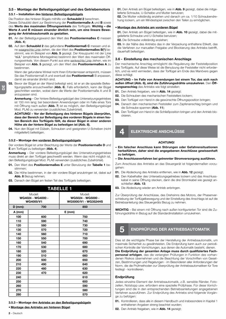
DE
2 – Deutsch
3.5 - Montage der Befestigungsbügel und des Getriebemotors3.5.1 – Installation des hinteren Befestigungsbügels
Die Position des hinteren Bügels mithilfe von Schaubild 2 berechnen.Dieses Schaubild dient zur Bestimmung der Positioniermaße A und B sowie des Werts des maximalen Öffnungswinkels des Torflügels. Wichtig – die Werte A und B müssen einander ähnlich sein, um eine lineare Bewe-gung der Antriebsautomatik zu gestatten.
01. An der Befestigungswand den Wert des Positioniermaßes C messen (Abb. 4);
02. Auf dem Schaubild 2 das gefundene Positioniermaß C messen und ei-ne waagrechte Linie ziehen, die den Wert des Positioniermaßes B(*) be-stim mt, wie im Beispiel von Abb. 5 gezeigt. Der Kreuzpunkt mit der Linie “r.i.l.” (empfohlene Montagelinie) bestimmt den Wert des maximalen Öff-nungswinkels. Von diesem Punkt aus eine senkrechte Linie ziehen, wie im Beispiel von Abb. 5 gezeigt, um den Wert des Positioniermaßes A zu bestimmen.
Wenn der gefundene Winkel nicht Ihren Erfordernissen entspricht, müssen Sie das Positioniermaß A und eventuell das Positioniermaß B anpassen, damit sie einander ähnlich sind.
03. Bevor der Bügel an der Wand befestigt wird, ist er an die spezielle Befes-tigungsplatte anzuschweißen (Abb. 6). Falls erforderlich, kann der Bügel geschnitten werden, wobei dann die Werte der Positioniermaße A und B anzupassen sind.
Anmerkung – Der hintere Befestigungsbügel des Untersetzungsgetriebes ist 150 mm lang; bei besonderen Anwendungen oder im Falle eines Tors mit Öffnung nach außen (Abb. 7) ist es möglich, den Befestigungsbügel Mod. PLA6 zu verwenden (zusätzliches Zubehörteil).
ACHTUNG! – Vor der Befestigung des hinteren Bügels überprüfen, dass der Bereich zur Befestigung des vorderen Bügels in einen fes-ten Bereich des Torflügels fällt, da dieser Bügel in einer anderen Höhe als der hintere Bügel zu befestigen ist (Abb. 8).
04. Nun den Bügel mit Dübeln, Schrauben und geeigneten U-Scheiben (nicht mitgeliefert) befestigen.
3.5.2 – Montage des vorderen Befestigungsbügels
Der vordere Bügel ist unter Beachtung der Werte der Positioniermaße D und E am Torflügel zu befestigen (Abb. 4).Anmerkung – Der vordere Befestigungsbügel des Untersetzungsgetriebes muss direkt an den Torflügel geschweißt werden. Wenn das nicht möglich ist, den Befestigungsbügel Mod. PLA8 verwenden (zusätzliches Zubehörteil).
01. Den Wert des Positioniermaßes E unter Benutzung der Tabelle 1 be-stimmen;
02. Die Höhe bestimmen, in der der vordere Bügel anzubringen ist, dabei auf Abb. 8 Bezug nehmen;
03. Danach den Bügel am festen Teil des Torflügels befestigen.
TABELLE 1Modell:
WG4024 - WG4000 -WG4000/V1
Modell:WG5024 - WG5000 -
WG5000/V1 - WG3524HS
D (mm): 700 850
A (mm) E (mm)
100 600 750110 590 740120 580 730130 570 720140 560 710150 550 700160 540 690170 530 680180 520 670190 510 660200 500 650210 490 640220 480 630230 470 620240 610250 600260 590270 580280 570
3.5.3 – Montage des Antriebs an den Befestigungsbügeln
• Montage des Antriebs am hinteren Bügel:
01. Den Antrieb am Bügel befestigen, wie in Abb. 9 gezeigt, dabei die mitge-lieferte Schraube, U-Scheibe und Mutter benutzen;
02. Die Mutter vollständig anziehen und danach um ca. 1/10 Schraubendre-hung lockern, um ein Mindestspiel zwischen den Teilen zu ermöglichen.
• Montage des Antriebs am vorderen Bügel:
01. Den Antrieb am Bügel befestigen, wie in Abb. 10 gezeigt, dabei die mit-gelieferte Schraube und U-Scheibe benutzen;
02. Die Schraube vollständig anziehen; 03. In der Nähe des Antriebs das in der Verpackung enthaltene Etikett, das
die Verfahren zur manuellen Freigabe und Blockierung des Antriebs betrifft, dauerhaft befestigen.
3.6 - Einstellung des mechanischen AnschlagsDer mechanische Anschlag ermöglicht die Regulierung der Feststellposition des Torflügels. Auf diese Weise ist die Benutzung der Feststeller nicht erforder-lich, und es wird vermieden, dass der Torflügel am Ende des Manövers gegen diese schlägt.
ACHTUNG – Im Falle von Anwendungen bei einem Tor, das sich nach außen öffnet (Abb. 6), sind die Zuführungsdrähte umzukehren. Den Öff-nungsanschlag des Antriebs wie folgt einstellen:
01. Den Antrieb freigeben, wie in Abb. 14 gezeigt;02. Die Schrauben des mechanischen Feststellers lockern;03. Den Torflügel von Hand in die gewünschte Öffnungsposition bringen;04. Danach den mechanischen Feststeller zum Zapfenanschlag bringen und
die Schraube spannen (Abb. 11);05. Den Torflügel von Hand in die Schließposition bringen und den Antrieb blo-
ckieren.
4 ELEKTRISCHE ANSCHLÜSSE
ACHTUNG!
– Ein falscher Anschluss kann Störungen oder Gefahrensituationen herbeiführen, daher sind die angegebenen Anschlüsse gewissenhaft zu befolgen.
– Die Anschlussverfahren bei getrennter Stromversorgung ausführen.
Zum Anschluss des Antriebs an das Steuergerät ist folgendermaßen vorzu-gehen:
01. Die Abdeckung des Antriebs entfernen, wie in Abb. 12 gezeigt;02. Den Kabelhalter des Untersetzungsgetriebes lockern und das Anschluss-
kabel in seine Öffnung stecken, dann die drei Stromkabel wie gezeigt an-schließen Abb. 13;
03. Die Abdeckung wieder am Antrieb anbringen.
Zur Überprüfung der Anschlüsse, des Drehsinns des Motors, der Phasenver-schiebung der Torflügelbewegung und der Einstellung des Anschlags ist auf die Betriebsanleitung des Steuergeräts Bezug zu nehmen.
WICHTIG – Bei einem mit Öffnung nach außen konfigurierten Tor sind die Zu-führungsdrähte in Bezug auf die Standardinstallation umzukehren.
5 ENDPRÜFUNG DER ANTRIEBSAUTOMATIK
Dies ist die wichtigste Phase bei der Herstellung der Antriebsautomatik, um maximale Sicherheit zu gewährleisten. Die Endprüfung kann auch zur periodi-schen Kontrolle der Vorrichtungen, aus denen die Automatik besteht, dienen.Die Endprüfung der gesamten Anlage muss durch qualifiziertes Fach-personal erfolgen, das die verlangten Prüfungen in Funktion des vorhan-denen Risikos übernehmen und die Beachtung der Vorschriften von Geset-zen, Be stimmungen und Regelungen - im Besonderen aller Anforderungen der Norm, die die Prüfmethoden zur Überprüfung der Antriebsautomatiken für Tore festlegt - kontrollieren.
EndprüfungJedes einzelne Element der Antriebsautomatik, z.B. sensible Ränder, Foto-zellen, Notstopp usw. erfordern eine spezielle Prüfphase. Für diese Vorrich-tungen sind die in den entsprechenden Betriebsanleitungen angegebenen Verfahren auszuführen. Zur Endprüfung des Antriebs sind folgende Vorgän-ge zu befolgen:
01. Kontrollieren, dass alle in diesem Handbuch und insbesondere in Kapitel 1 enthaltenen Angaben streng beachtet wurden;
02. Den Antrieb freigeben, wie in Abb. 14 gezeigt;

DE
Deutsch – 3
03. Kontrollieren, dass der Torflügel beim Öffnen und Schließen mit einer Kraft von nicht mehr als 390 N (ca. 40 kg) von Hand bewegt werden kann;
04. Den Antrieb blockieren und die Stromversorgung anschließen;05. Mithilfe der vorgesehenen Steuer- und Stoppvorrichtungen (Schlüsselwä-
hlschalter, Bedienungsknöpfe oder Funksender) Tests zum Öffnen, Sch-ließen und Stoppen des Tors vornehmen und kontrollieren, ob das Verhal-ten dem vorgesehenen entspricht;
06. Eins nach dem anderen den einwandfreien Betrieb aller in der Anlage vor-handenen Sicherheitsvorrichtungen überprüfen (Fotozellen, sensible Rän-der, Notstopp usw.) und kontrollieren, ob das Verhalten dem vorgesehe-nen entspricht;
07. Einen Schließvorgang steuern und die Aufprallkraft des Tors gegen den me chanischen Anschlag überprüfen. Bei Bedarf den Druck prüfen und ab-lassen, um eine Einstellung zu finden, die bessere Ergebnisse erzielt;
08. Wenn die durch die Torflügelbewegung herbeigeführten Gefahrensituatio-nen durch Begrenzung der Aufprallkraft geschützt wurden, ist Kraftmes-sung gemäß den Vorschriften der Norm EN 12445 vorzunehmen;
Anmerkung – Der Antrieb ist nicht mit Vorrichtungen zur Drehmomentregu-lierung ausgestattet, daher ist diese Regulierung dem Steuergerät anvertraut.
InbetriebsetzungDie Inbetriebsetzung darf erst erfolgen, nachdem alle Phasen der Antriebsprü-fung mit positivem Ergebnis ausgeführt wurden. Zur Inbetriebsetzung ist auf die Betriebsanleitung des Steuergeräts Bezug zu nehmen.
WICHTIG – Die teilweise oder in “provisorischen” Situationen erfolgen-de Inbetriebsetzung ist verboten.
6 WARTUNG DES PRODUKTS
Um das Sicherheitsniveau konstant zu halten und eine maximale Dauer der ge-samten Antriebsautomatik zu garantieren, ist eine regelmäßige Wartung erfor-derlich.Die Wartung muss unter vollständiger Beachtung der Sicherheitsvorschriften dieses Handbuchs und gemäß den Vorschriften der geltenden Gesetze und Bestimmungen erfolgen. Für den Getriebemotor ist eine programmierte War-tung innerhalb von max. 6 Monaten erforderlich.
Wartungsverfahren:
01. Alle Stromversorgungsquellen trennen.02. Den Verschleißzustand aller Materialien, aus denen die Antriebsautomatik
besteht, überprüfen, mit besonderem Augenmerk auf Erosions- oder Oxi-dationserscheinungen an den strukturellen Teilen. Die Teile, die keine aus-reichende Sicherheit bieten, sind auszuwechseln.
03. Überprüfen, dass die Schraubanschlüsse angemessen festgeschraubt sind.
04. Überprüfen, dass das Mutterschloss und die Schnecke angemessen ge-sc hmiert sind.
05. Den Abnutzungszustand aller beweglichen Teile überprüfen und gegebe-nenfalls die verschlissenen Teile auswechseln.
06. Die Stromversorgungsquellen wieder anschließen und alle Tests und Prü-fungen vornehmen, die in Kapitel 5 vorgesehen sind.
Für die weiteren in der Anlage vorhandenen Vorrichtungen ist auf deren Be-triebsanleitungen Bezug zu nehmen.
ENTSORGUNG DES PRODUKTS
Dieses Produkt ist Teil der Antriebsautomatik und ist daher mit dieser zu entsorgen.
Wie die Installationsverfahren ist auch die Verschrottung am Lebensende die-ses Produkts von Fachpersonal vorzunehmen.
Dieses Produkt besteht aus verschiedenen Materialtypen: Einige können recy-celt werden, andere sind zu entsorgen. Informieren Sie sich bitte über die Re-cycling- oder Entsorgungssysteme, die von den in Ihrem Land geltenden Be-stimmungen für diese Produktkategorie vorgesehen sind.
ACHTUNG! – Einige Teile des Produkts können Schad- oder Gefahrenstoffe enthalten, die bei Zerstreuung in der Umwelt schädliche Auswirkungen auf die Umwelt und auf die menschliche Gesundheit haben könnten.
Wie vom seitlichen Symbol angezeigt, ist es verboten, dieses Produkt in den Hausmüll zu werfen. Zur Entsorgung ist daher die “getrennte Müllsammlung” nach den Methoden vorzunehmen, die von den in Ihrem Land geltenden Bestimmungen vorgesehen sind. Das Produkt kann beim Kauf eines neuen gleichwertigen Produkts auch an den Händler zurückgegeben werden.
ACHTUNG! – Die auf örtlicher Ebene geltenden Bestimmungen können im Fall einer rechtswidrigen Entsorgung dieses Produkts schwere Strafen vorsehen.
Beständigkeit des Produkts
Die Beständigkeit ist die durchschnittliche Brauchbarkeitsdauer des Produkts. Der Beständigkeitswert wird stark durch den Belastungsindex der von der An-triebsautomatik ausgeführten Manöver, d.h. die Summe aller zum Verschleiß des Produkts beitragenden Faktoren, beeinflusst (siehe Tabelle 2).
Um die wahrscheinliche Lebensdauer Ihrer Antriebsautomatik zu bestimmen, gehen Sie folgendermaßen vor:
01. Den Belastungsindex berechnen, indem Sie die Prozentwerte der in Ta-belle 2 enthaltenen Posten summieren;
02. In Schaubild A vom eben gefundenen Wert eine senkrechte Linie ziehen, bis Sie auf die Kurve treffen, danach eine waagrechte Linie ziehen, bis Sie auf die Linie der “Betätigungszyklen” treffen. Der bestimmte Wert stellt die geschätzte Lebensdauer Ihres Produkts dar.
Die Lebensdauerschätzung erfolgt auf der Grundlage der Entwurfsberechnun-gen und der an Prototypen durchgeführten Tests. Da es sich um eine Schät-zung handelt, stellt sie natürlich keine Garantie für die tatsächliche Lebensdau-er des Produkts dar.
TABELLE 2Belastungsindex
WG4024WG4000
WG4000/V1
WG5024WG5000
WG5000/V1WG3524HS
Torflügelgewicht:
> 100 kg 10 % 0 % 10 %> 200 kg 20 % 10 % 20 %> 300 kg 30 % 20 % –––> 400 kg ––– 30 % –––
Torflügellänge:1 - 2 m 20 % 0 % 10 %2 - 3 m ––– 10 % 20 %
3 - 3,5 m ––– 20 % –––Verwendungstemperatur: 20 % 20 % 20 %Blinder Torflügel: 15 % 15 % 15 %Installation in windigem Gebiet: 15 % 15 % 15 %
Belastungsindex (%)
0
0
25.000
50.000
75.000
100.000
125.000
10 20 30 40 50 60 70 80 90 100
SCHAUBILD A
Bet
ätig
ung
szyk
len
Beispiel für die Berechnung der Beständigkeit eines Antriebs Wingo WG5024 (auf Tabelle 2 und Schaubild A Bezug nehmen):
- Torflügelgewicht = 200 kg (Belastungsindex = 10%)- Torflügellänge = 2,5 m (Belastungsindex = 10%)- keine weiteren Belastungselemente vorhandenBelastungsindex insgesamt = 20%
Geschätzte Beständigkeit = 80.000 Betätigungszyklen

DE
4 – Deutsch
CE-Konformitätserklärung und Einbauerklärung der „unvollständigen Maschine”
Erklärung in Übereinstimmung mit den Richtlinien: 2004/108/EG (EMV); 2006/42/EG (MD) Anlage II, Teil B
Anmerkung - Der Inhalt dieser Erklärung entspricht den Angaben im offiziellen Dokument, das im Sitz der Nice S.p.A. hinterlegt ist und der letzten verfüg-baren Revision vor dem Druck dieser Anleitung. Dieser Text wurde aus redaktionellen Gründen angepasst. Die Kopie der Original-Erklärung kann bei der Firma Nice S.p.A. (TV) I. angefordert werden.
Nummer der Erklärung: 143/WINGO Revision: 9 Sprache: DE
Name des Herstellers: NICE s.p.a.Adresse: Via Pezza Alta N°13, 31046 Rustignè di Oderzo (TV) Italy.Bevollmächtigte Person zum Zusammenstellen der technischen Unterlagen: NICE s.p.a. – Via Pezza Alta N°13, 31046 Rustignè di Oderzo (TV) ItalyArt des Produkts: Elektromechanisches Getriebe für Drehtore.Modell / Typ: WG4000, WG4000/V1, WG5000, WG5000/V1, WG4024, WG5024, WG3524HSZubehör: Kein Zubehör.
Der Unterzeichnende Mauro Sordini, in seiner Funktion als Chief Executive Officer, erklärt auf eigene Verantwortung, dass die oben genannten Produkte den Bestimmungen entsprechen, die in folgenden Richtlinien enthalten sind:• RICHTLINIE 2004/108/EG DES EUROPÄISCHEN PARLAMENTS UND DES RATES vom 15. Dezember 2004 zur Angleichung der Rechtsvorschriften
der Mitgliedsstaaten über die elektromagnetische Verträglichkeit und zur Aufhebung der Richtlinie 89/336/EWG, gemäß den folgenden harmonisierten Normen: EN 61000-6-2:2005; EN 61000-6-3:2007 + A1:2011.
Außerdem entspricht das Produkt folgender Richtlinie, entsprechend der vorgesehenen Anforderungen für die „unvollständigen Maschinen”:• Richtlinie 2006/42/EG DES EUROPÄISCHEN PARLAMENTS UND DES RATES vom 17. Mai 2006 über Maschinen, welche die Richtlinie 95/16/EG än-
dert (Überarbeitung)– Hiermit wird erklärt, dass die entsprechenden technischen Unterlagen in Übereinstimmung mit Anlage VII B der Richtlinie 2006/42/EG zusammengestellt
und die folgenden wesentlichen Anforderungen eingehalten wurden: 1.1.1 - 1.1.2 - 1.1.3 - 1.2.1 -1.2.6 - 1.5.1 -1.5.2 - 1.5.5 - 1.5.6 - 1.5.7 - 1.5.8 - 1.5.10 - 1.5.11.– Der Hersteller verpflichtet sich, die Informationen über die „unvollständige Maschine” auf Verlangen an die nationalen Behörden weiterzuleiten, wobei die
eignen Rechte des geistigen Eigentums beibehalten werden. – Wenn die „unvollständige Maschine” in einem europäischen Land in Betrieb genommen wird, deren offizielle Sprache nicht der in dieser Erklärung ent-
spricht, ist der Importeur verpflichtet, dieser Erklärung die entsprechende Übersetzung beizulegen.– Wir weisen darauf hin, dass die „unvollständige Maschine” erst dann in Betrieb genommen werden darf, wenn gegebenenfalls festgestellt wurde, dass
die Maschine, in die die unvollständige Maschine eingebaut werden soll, den Bestimmungen der Richtlinie 2006/42/EG entspricht.
Außerdem entspricht das Produkt folgenden Normen: EN 60335-1:2002 + A1:2004 + A11:2004 + A12:2006 + A2:2006 + A13:2008 + A14:2010 + A15:2011; EN 60335-2-103:2003 + A11:2009.
Das Produkt entspricht, auf die anwendbaren Teile begrenzt, folgenden Normen: EN 13241-1:2003 + A1:2011; EN 12445:2002; EN 12453:2002; EN 12978:2003 + A1:2009.
Oderzo, 30. April 2015Ing. Mauro Sordini
(Chief Executive Officer)
HINWEISE: • Alle hier wiedergegebenen technischen Merkmale beziehen sind auf eine Umgebungstemperatur von 20°C (± 5°C). • Die Firma Nice S.p.a. behält sich das Recht vor, jederzeit Änderungen am Produkt vorzunehmen, falls sie es für notwendig hält, wobei jedoch dieselbe Funktionstüchtigkeit und derselben Bestimmungszweck beibehalten wird.
WG4024 WG5024 WG4000 WG4000/V1 WG5000 WG5000/V1 WG3524HSTypologie Elektromechanischer Antrieb mit Untersetzungsgetriebe für FlügeltoreSpeisung 24 V 24 V 230 V~ 50 Hz 120 V~ 60 Hz 230 V~ 50 Hz 120 V~ 60 Hz 24 VBedarfsspitze 3,5 A 3,5 A 1,5 A 1,5 A 1,5 A 2,5 A 5 ANennaufnahme 2 A 2 A 0,5 A 0,5 A 0,5 A 1 A 3 AMax. Leistungsaufnahme 85 W 85 W 200 W 200 W 200 W 200 W 120 WNominale Leistungsaufnahme 50 W 50 W 130 W 130 W 130 W 130 W 72 WSchutzgrad IP 44 IP 44 IP 44 IP 44 IP 44 IP 44 IP 44Lauf 320 mm 470 mm 320 mm 320 mm 470 mm 470 mm 470 MMLeergeschwindigkeit 0,018 m/s 0,016 m/s 0,016 m/s 0,020 m/s 0,013 m/s 0,016 m/s 0,040 m/sVoller Schub 1500 N 1500 N 1500 N 1500 N 1700 N 1700 N 1500 NNennschub 500 N 500 N 500 N 500 N 600 N 600 N 650 NBetriebstemperatur -20 °C bis +50 °CZyklen h bei Nenndrehmoment 40 40 30 30 30 30 30Beständigkeit geschätzt zwischen ca. 80.000 und 250.000 Betätigungszyklen gemäß den in Tabelle 2 angeführten BedingungenIsolierklasse A A F F F F FAbmessungen (mm) 770 x 98 x 95 h 920 x 98 x 95 h 770 x 98 x 95 h 770 x 98 x 95 h 920 x 98 x 95 h 920 x 98 x 95 h 920 x 98 x 95 hGewicht (kg) 6 6 6 6 6 6 6
TECHNISCHE MERKMALE DES PRODUKTS

PL
Polski – 1
1 OGULNE OSTRZEŻENIA I ŚRODKI BEZPIECZEŃSTWA
1.1 - Uwagi dotyczące bezpieczeństwa• UWAGA! – Niniejsza instrukcja zawiera ważne wskazówki i ostrzeże-
nia dla bezpieczeństwa osób.
Niepoprawnymontażmożepowodowaćpoważnezranienia.Przedrozpo-częciempracynależydokładnieprzeczytaćwszystkierozdziałyinstrukcjiob-sługi.Wprzypadkuwątpliwości,przerwaćmontażizwrócićsiępowyjaśnie-niadoSerwisuObsługiKlientaNice.
• UWAGA! – Zgodnie z najnowszymi przepisami europejskimi, wykona-nie drzwi lub bramy automatycznej musi być zgodne z normami Dy-rektywy 98/37/WE (Dyrektywa Maszynowa) a w szczególności, z nor-mami EN 12445; EN 12453; EN 12635 i EN 13241-1, które pozwalają na deklarację założonej zgodności automatyzacji. W związku z tym, wszystkie czynności montażowe, podłączeniowe, testujące i konser-wacyjne produktu muszą być wykonane przez wykwalifikowanego technika!
• UWAGA! – Ważne Wskazania: Instrukcję należy przechowywać dla ewentualnych działań w przyszłości, konserwacji i likwidacji produktu.
1.2 - Ostrzeżenia do montażu•Przedrozpoczęciemmontażu,sprawdzićczyproduktnadajesiędoautoma-tyzacjiwaszejbramylubdrzwi(patrzrozdział3i“Cechytechniczneproduk-tu”).Jeżelinienadajesię,NIEinstalować.
•Przygotowaćwsiecizasilającejinstalacji,urządzeniewyłączającezodległo-ściąotwarciakontaktów,którapozwolinacałkowitewyłączeniewwarun-kachprzewidzianychprzezkategorięnadmiernegonapięciaIII.
• wszystkie czynności montażowe i konserwacyjne muszą być wyko-nywane z automatem odłączonym od zasilania elektrycznego.Jeżeliurządzenieodcinającezasilanieniejestwidocznezmiejsca,gdzieznajdujesięautomat,przedrozpoczęciempracynależyumieścićnaurządzeniuodci-nającymkartkęznapisem“UWAGA!TRWAKONSERWACJA”.
•Podczasmontażunależydelikatnieobchodzićsięzautomatemunikającprzygnieceniago,uderzeń,upadkówlubkontaktuzjakimikolwiekpłynami.Niezostawiaćproduktuwpobliżuźródełciepłainienarażaćnadziałanieognia.Wszystkieteczynnościmogągouszkodzićispowodowaćzłedzia-łanielubzagrożenie.Gdytonastąpi,natychmiastzaprzestaćmontowanieizwrócićsiędoSerwisuNice.
•Niewykonywaćmodyfikacjinażadnejczęściproduktu.Niedozwoloneczyn-nościmogąspowodowaćzłefunkcjonowanie.Producentnieponosiżadnejodpowiedzialnościzaszkodywynikającezmodyfikacjiproduktu.
•Jeżelibramalubdrzwidoautomatyzacjisąwyposażonewdrzwiprzejściowe(dlapieszych),należywyposażyćinstalacjęwsystemkontroli,któryzahamujedziałalnośćsilnika,gdydrzwiprzejściowebędąotwarte.
•Sprawdzić,czynieistniejąmiejsca-pułapkiwkierunkuczęścistałych,gdyskrzydłobramyznajdujesięwpozycjimaksymalnegoOtwarcia;ewentualnieosłonićtakieczęści.
•Ściennypanelprzyciskowysterowania,musibyćumieszczonytak,abybyłwidocznyautomat,dalekoodczęściwruchu,nawysokościminimalnej1,5modpodłożainiedostępnydlaosóbpostronnych.
•Materiał,wktórybyłzapakowanyproduktmusibyćusuniętyzgodniezlokal-nym prawem.
2 OPIS PRODUKTU I PRZEZNACZONE UŻYCIE
Niniejszeurządzenie jestprzeznaczonedoużytkuwautomatycebramlubdrzwi skrzydłowych,wykorzystywanychwyłączniedlacelówprywatnych.UWAGA! – Jakiekolwiek użycie inne od wskazanego i w warunkach in-nych od przedstawionych w tej instrukcji jest niewłaściwe i zabronione!
Produkttomotoreduktorelektromechaniczny,wyposażonywsilniknaprąd
stały24Vlubprądprzemienny230V(wzależnościodwybranegomodelu)iwreduktorześlimakiem.MotoreduktorjestzasilanyzzewnętrznejCentralisterowania,doktórejmusibyćpodłączony.Wprzypadkuodcięciaenergiielektrycznej(black-out),możliwejestprzesunię-cie‘ręczne’skrzydełbramyodblokowującręczniemotoreduktor.
rys. 1przedstawiawszystkieelementyobecnewwyposażeniu(wzależnościod wybranego modelu):
[a] - motoreduktor elektromechaniczny[b] - przednia listwa (do zamocowania motoreduktora na skrzydle bramy)[c]-tylnalistwaipłyta(dozamocowaniamotoreduktornaścianie)[d]-drobnewyrobymetalowe(śruby,podkładki,itd.)[e]-kluczedoręcznegoodblokowaniamotoreduktora.
3 MONTAŻ
3.1 - Weryfikacja przed montażemPrzedrozpoczęciemmontażu,należysprawdzićcałośćelementówproduk-tu,zgodnośćwybranegomodeluiodpowiedniedomontażuwarunkiprze-strzenne.
WAŻNE – Motoreduktor nie może automatyzować ręcznej bramy, nie posiadającej pewnej i bezpiecznej konstrukcji mechanicznej. Nie może rozwiązać usterek spowodowanych niepoprawnym montażem bramy lub jej nieodpowiednią konserwacją.
3.2 - Zgodność bramy do automatyzacji i środowiska otaczającego
•Sprawdzićczystrukturamechanicznabramynadajesiędoautomatyzacjizgodniezprawemobowiązującymnaterytorium(ewentualnieodnieśćsiędodanych umieszczonych na etykiecie bramy).
•PoruszającręcznieskrzydłobramypodczasOtwarciaiZamknięcia,spraw-dzić,czyruchprzebiegaz jednakowymtarciemi jednostajniewkażdympunkcieprzebiegu(niemogąistniećpunktywiększegonacisku).
•Sprawdzić,czyskrzydłobramypozostajewrównowadze,czyliniechwie-jesię,gdyjestręcznieporuszanewróżnysposóblubpozostawionenieru-chomo.
•Sprawdzić,czywokółmotoreduktoraznajdujesięwystarczającodużomiej-scanaręczneodblokowanieskrzydełbramy,włatwyibezpiecznysposób.
•Sprawdzić,czypowierzchniewybranedomontażuproduktusąwytrzymałeigwarantująstabilnezamocowanie.
•Sprawdzić,czystrefazamocowaniamotoreduktoraodpowiadajegorozmia-rom, patrz rys. 2:poprawnyruchOtwarciabramyisiła,którąsilnikwykonujedootwarcia,zależąodpozycji,wktórejjestzamontowanatylnalistwamocu-jąca.Następnie,przedkontynuacjąmontażunależyodnieśćsiędowykresu 2,abyokreślićmaksymalnykątOtwarciaskrzydłaisiłęsilnika,odpowiadają-ce instalacji.
3.3 - Ograniczenia w zastosowaniu produktuPrzedwykonaniemmontażuproduktusprawdzić,czyskrzydłobramyposiadarozmiaryiciężarmieszczącesięwlimitachprzedstawionychnawykresie 1.
3.4 - Prace przygotowania do montażuRys. 3przedstawiaprzykładinstalacjiautomatyzacjizrealizowanejprzypomo-cy elementów Nice.Elementysąumieszczonenapodstawietypowegosche-matu.Odnoszącsiędorys. 3,ustalićpozycję,wktórejzostaniezamontowanykażdyzkomponentówprzewidzianychwinstalacjiischematpodłączenia.
Elementy do realizacji kompletnej instalacji (rys. 3):
A - Motoreduktory elektromechaniczneB - Dwie fotokomórkiC - Dwa ograniczniki ruchu (w Otwarciu)D - Kolumny na fotokomórkiE-MigającywskaźnikzwbudowanąantenąF-PrzełączniknakluczlubklawiaturacyfrowaG - Centrala sterownicza
3.5 - Montaż listew mocujących i motoreduktora3.5.1 – Montaż tylniej listwy mocującej
Obliczyćpozycjętylnejlistwyużywającschematu 2.Schematsłużydookreśleniawysokości A i B oraz wartości maksymalnego kąta otwarcia skrzydła.Ważne – Wartości A i B muszą być podobne, aby pozwolić na linearny ruch automatu.
POLSKIInstrukcja przetłumaczona z języka włoskiego
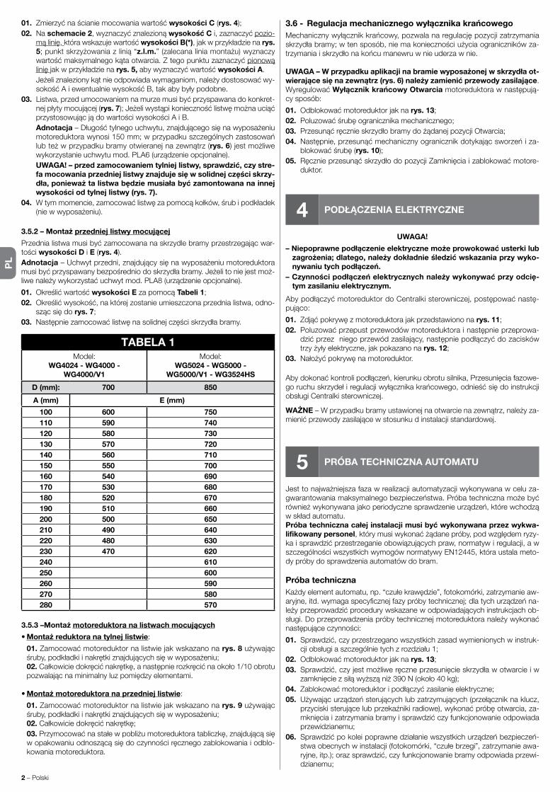
PL
2 – Polski
01. Zmierzyćnaścianiemocowaniawartośćwysokości C (rys. 4);02. Na schemacie 2,wyznaczyćznalezionąwysokość Ci,zaznaczyćpozio-
mąlinię, którawskazujewartośćwysokości B(*),jakwprzykładzienarys. 5;punktskrzyżowaniazlinią“z.l.m.”(zalecanaliniamontażu)wyznaczywartośćmaksymalnegokątaotwarcia.Ztegopunktuzaznaczyćpionowąlinięjakwprzykładzienarys. 5,abywyznaczyćwartośćwysokości A.
Jeżeliznalezionykątnieodpowiadawymaganiom,należydostosowaćwy-sokośćAiewentualniewysokośćB,takabybyłypodobne.
03. Listwa,przedumocowaniemnamurzemusibyćprzyspawanadokonkret-nejpłytymocującej(rys. 7);JeżeliwystąpikoniecznośćlistwęmożnauciąćprzystosowującjądowartościwysokościAiB.
Adnotacja–Długośćtylnegouchwytu,znajdującegosięnawyposażeniumotoreduktorawynosi150mm;wprzypadkuszczególnychzastosowańlubteżwprzypadkubramyotwieranejnazewnątrz(rys. 6)jestmożliwewykorzystanieuchwytumod.PLA6(urządzenieopcjonalne).
UWAGA! – przed zamocowaniem tylniej listwy, sprawdzić, czy stre-fa mocowania przedniej listwy znajduje się w solidnej części skrzy-dła, ponieważ ta listwa będzie musiała być zamontowana na innej wysokości od tylnej listwy (rys. 7).
04. Wtymmomencie,zamocowaćlistwęzapomocąkołków,śrubipodkładek(niewwyposażeniu).
3.5.2 – Montaż przedniej listwy mocującej
Przednialistwamusibyćzamocowananaskrzydlebramyprzestrzegającwar-tościwysokości D i E (rys. 4).Adnotacja–Uchwytprzedni,znajdującysięnawyposażeniumotoreduktoramusibyćprzyspawanybezpośredniodoskrzydłabramy.Jeżelitoniejestmoż-liwenależywykorzystaćuchwytmod.PLA8(urządzenieopcjonalne).
01. Określićwartośćwysokości EzapomocąTabeli 1;02. Określićwysokość,naktórejzostanieumieszczonaprzednialistwa,odno-
szącsiędorys. 7;03. Następniezamocowaćlistwęnasolidnejczęściskrzydłabramy.
TABELA 1Model:
WG4024 - WG4000 -WG4000/V1
Model:WG5024 - WG5000 -
WG5000/V1 - WG3524HS
D (mm): 700 850
A (mm) E (mm)
100 600 750110 590 740120 580 730130 570 720140 560 710150 550 700160 540 690170 530 680180 520 670190 510 660200 500 650210 490 640220 480 630230 470 620240 610250 600260 590270 580280 570
3.5.3 –Montaż motoreduktora na listwach mocujących
• Montaż reduktora na tylnej listwie:
01.Zamocowaćmotoreduktornalistwiejakwskazanonarys. 8używającśruby,podkładkiinakrętkiznajdującychsięwwyposażeniu;
02.Całkowiciedokręcićnakrętkę,anastępnierozkręcićnaokoło1/10obrotupozwalającnaminimalnyluzpomiędzyelementami.
• Montaż motoreduktora na przedniej listwie:
01.Zamocowaćmotoreduktornalistwiejakwskazanonarys. 9używającśruby,podkładkiinakrętkiznajdującychsięwwyposażeniu;
02.Całkowiciedokręcićnakrętkę; 03.Przymocowaćnastałewpobliżumotoreduktoratabliczkę,znajdującąsięwopakowaniuodnoszącąsiędoczynnościręcznegozablokowaniaiodblo-kowania motoreduktora.
3.6 - Regulacja mechanicznego wyłącznika krańcowegoMechanicznywyłącznikkrańcowy,pozwalanaregulacjępozycjizatrzymaniaskrzydłabramy;wtensposób,niemakoniecznościużyciaogranicznikówza-trzymaniaiskrzydłonakońcumanewruwnieuderzawnie.
UWAGA – W przypadku aplikacji na bramie wyposażonej w skrzydła ot-wierające się na zewnątrz (rys. 6) należy zamienić przewody zasilające. WyregulowaćWyłącznik krańcowy Otwarcia motoreduktorawnastępują-cy sposób:
01. Odblokowaćmotoreduktorjaknarys. 13;02. Poluzowaćśrubęogranicznikamechanicznego;03. PrzesunąćręcznieskrzydłobramydożądanejpozycjiOtwarcia;04. Następnie,przesunąćmechanicznyogranicznikdotykającsworzeńiza-
blokowaćśrubę(rys. 10);05. RęcznieprzesunąćskrzydłodopozycjiZamknięciaizablokowaćmotore-
duktor.
4 PODŁĄCZENIA ELEKTRYCZNE
UWAGA!
– Niepoprawne podłączenie elektryczne może prowokować usterki lub zagrożenia; dlatego, należy dokładnie śledzić wskazania przy wyko-nywaniu tych podłączeń.
– Czynności podłączeń elektrycznych należy wykonywać przy odcię-tym zasilaniu elektrycznym.
AbypodłączyćmotoreduktordoCentralkisterowniczej,postępowaćnastę-pująco:
01. Zdjąćpokrywęzmotoreduktorajakprzedstawiononarys. 11;02. Poluzowaćprzepustprzewodówmotoreduktorainastępnieprzeprowa-
dzićprzezniegoprzewódzasilający,następniepodłączyćdozaciskówtrzyżyłyelektryczne,jakpokazanonarys. 12;
03. Nałożyćpokrywęnamotoreduktor.
Abydokonaćkontrolipodłączeń,kierunkuobrotusilnika,Przesunięciafazowe-goruchuskrzydełiregulacjiwyłącznikakrańcowego,odnieśćsiędoinstrukcjiobsługiCentralkisterowniczej.
WAŻNE–Wprzypadkubramyustawionejnaotwarcienazewnątrz,należyza-mienićprzewodyzasilającewstosunkudinstalacjistandardowej.
5 PRÓBA TECHNICZNA AUTOMATU
Jesttonajważniejszafazawrealizacjiautomatyzacjiwykonywanawceluza-gwarantowaniamaksymalnegobezpieczeństwa.Próbatechnicznamożebyćrównieżwykonywanajakoperiodycznesprawdzenieurządzeń,którewchodząwskładautomatu.Próba techniczna całej instalacji musi być wykonywana przez wykwa-lifikowany personel,którymusiwykonaćżądanepróby,podwzględemryzy-kaisprawdzićprzestrzeganieobowiązującychpraw,normatywiregulacji,awszczególnościwszystkichwymogównormatywyEN12445,któraustalameto-dy próby do sprawdzenia automatów do bram.
Próba technicznaKażdyelementautomatu,np.“czułekrawędzie”,fotokomórki,zatrzymanieaw-aryjne,itd.wymagaspecyficznejfazypróbytechnicznej;dlatychurządzeńna-leżyprzeprowadzićprocedurywskazanewodpowiadającychinstrukcjachob-sługi.Doprzeprowadzeniapróbytechnicznejmotoreduktoranależywykonaćnastępująceczynności:
01. Sprawdzić,czyprzestrzeganowszystkichzasadwymienionychwinstruk-cjiobsługiaszczególnietychzrozdziału1;
02. Odblokowaćmotoreduktorjaknarys. 13;03. Sprawdzić,czyjestmożliweręczneprzesunięcieskrzydławotwarcieiw
zamknięciezsiłąwyższąniż390N(około40kg);04. Zablokowaćmotoreduktoripodłączyćzasilanieelektryczne;05. Używającurządzeństerującychlubzatrzymujących(przełączniknaklucz,
przyciskisterującelubprzekaźnikiradiowe),wykonaćpróbęotwarcia,za-mknięciaizatrzymaniabramyisprawdzićczyfunkcjonowanieodpowiadaprzewidzianemu;
06. Sprawdzićpokoleipoprawnedziałaniewszystkichurządzeńbezpieczeń-stwaobecnychwinstalacji(fotokomórki,“czułebrzegi”,zatrzymanieawa-ryjne,itp.);orazsprawdzić,czyfunkcjonowaniebramyodpowiadaprzewi-dzianemu;

PL
Polski – 3
07. Zlecićmanewrzamknięciaisprawdzićsiłęuderzeniaskrzydławogra-nicznikmechanicznegowyłącznikakrańcowego.Jeżeliwystąpikoniecz-ność,spróbowaćrozładowaćnacisk,iznaleźćregulację,któradalepszerezultaty;
08. Jeżeliniebezpiecznesytuacjepowodowaneruchemskrzydłazostaływy-eliminowanezapomocąograniczeniasiłyuderzenianależydokonaćpo-miarusiływedługnormatywyEN12445;
Adnotacja–Motoreduktorniejestwyposażonywurządzeniaregulacyjnemo-mentu,czylitakieregulacjesąpowierzoneCentralcesterowniczej.
Wprowadzenie do użytkuWprowadzeniedoużytkumożenastąpićtylkopowykonaniuwszystkichfazpróbytechnicznejmotoreduktora,zakończonychpozytywnieiinnychobec-nychurządzeń.Abywykonaćwprowadzeniedoużytkuodnieśćsiędoinstruk-cjiobsługiCentralkisterowniczej.
WAŻNE – Zabrania się częściowego uruchamiania lub w sytuacjach “prowizorycznych”.
6 KONSERWACJA PRODUKTU
Abyzachowaćstałypoziombezpieczeństwaizagwarantowaćmaksymalnątrwałośćautomatunależywykonywaćregularnąkonserwację.Konserwacjamusibyćwykonywanazgodniezzaleceniamiinstrukcjiobsługidotyczącymibezpieczeństwainapodstawieobowiązującychprzepisówinor-matyw. Dla motoreduktora konieczna jest konserwacja zaprogramowana na maksymalnyokresdo6miesięcy.
Czynnościkonserwacyjne:
01. Odciąćwszystkieźródłazasilaniaelektrycznego.02. Sprawdzićstanzużyciawszystkichmateriałówwchodzącychwskładau-
tomatuzeszczególnąuwagąnaerozjęlubutlenienieczęścikonstrukcji;zastąpićelementynieprzedstawiającewystarczającejgwarancji.
03. Sprawdzićczypołączenianaśrubysąodpowiedniodociśnięte.04. Sprawdzićczyspiralaiślimaksąodpowiednionasmarowane.05. Sprawdzićstanzużyciaruchomychczęściiewentualniezastąpićzużyte.06. Ponowniepodłączyćźródłazasilaniaelektrycznegoiwykonaćwszystkie
próby przedstawione w rozdziale 5.Dlainnychurządzeńobecnychwinstalacjiodnieśćsiędokonkretnychinstruk-cjiobsługi.
LIKWIDACJA PRODUKTU
Ten produkt jest częścią integracyjną automatu i dlatego, musi być zli-kwidowany razem z nim.
Takjakprzyczynnościachmontażowych,zarównopozużyciuproduktu,czyn-nościeliminacjimusząbyćwykonaneprzezwykwalifikowanypersonel.
Produktskładasięzróżnychmateriałów:niektóremogąbyćodzyskiwane,in-nemusząbyćzlikwidowane.Dowiedzciesięosystemachodzyskiwanialubli-kwidacjiprzewidzianychwprawieobowiązującymnawaszymterytorium,dlatej kategorii produktu.
Uwaga!–niektóreczęściproduktumogązawieraćsubstancjezanieczyszcza-jącelubniebezpieczne,którerozproszone,mogłybyzagrażaćśrodowiskuna-turalnemu i ludzkiemu zdrowiu.
Jakwskazujesymbolobok,zabraniasięwyrzucaniaproduktudoodpadówdomowych.Należywykonać“selektywnązbiór-kęodpadów”dlalikwidacji,zgodniezmetodamiprzewidziany-miprzepisamiobowiązującyminawaszymterytoriumluboddaćproduktsprzedawcywmomenciezakupunowegorównoważ-nego produktu.
Uwaga!–przepisyobowiązującenapoziomielokalnymmogąprzewidywaćpoważnekarywprzypadkunielegalnejlikwidacjitegoproduktu.
Trwałość produktu
Trwałośćtośredniokresżywotnościproduktu.Wartośćtrwałościjestzależnaodwskaźnikauciążliwościmanewrówwykonanychprzezautomat:czylisu-mąwszystkichfaktorówskładającychsięnazużycieproduktu(patrzTabela2).
Abyustalićmożliwątrwałośćwaszegoautomatunależypostępowaćwnastę-pującysposób:
01. ObliczyćwskaźnikuciążliwościdodającwartościwprocentachznajdującesięwTabeli 2;
02. W Schemacie Aodotrzymanejwartości,zaznaczyćpionowalinię,ażdoskrzyżowaniakrzywej;ztegopunktuzaznaczyćliniępionową,ażdoskrzy-żowanialinii“cyklemanewrów”.Otrzymanawartośćjestszacowanątrwa-łością waszego produktu.
Szacowanietrwałościjestwykonywanenapodstawieobliczeńprojektowychiwynikówpróbprzeprowadzonychnaprototypach.Będącwartościąszacunko-wą,niegwarantujerzeczywistejtrwałościproduktu.
TABELA 2Wskaźnik uciążliwości
WG4024WG4000
WG4000/V1
WG5024WG5000
WG5000/V1WG3524HS
Ciężar skrzydła:
> 100 kg 10 % 0 % 10 %> 200 kg 20 % 10 % 20 %> 300 kg 30 % 20 % –––> 400 kg ––– 30 % –––
Długość skrzydła:1 - 2 m 20 % 0 % 10 %2 - 3 m ––– 10 % 20 %
3 - 3,5 m ––– 20 % –––Temperatura pracy: 20 % 20 % 20 %Ślepe skrzydło: 15 % 15 % 15 %Montaż w strefie wietrznej: 15 % 15 % 15 %
0
0
25.000
50.000
75.000
100.000
125.000
10 20 30 40 50 60 70 80 90 100
SCHEMAT A
Wskaźnik uciążliwości (%)
Cyk
le m
anew
rów
Przykład obliczania trwałości motreduktora TWingo WG5024 (Odnieść się do Tabeli 2 i do schematu A):
-ciężarskrzydła=200kg(wskaźnikuciążliwości=10%)-długośćskrzydła=2,5m(wskaźnikuciążliwości=10%)-brakinnychelementówzużyciaCałkowitywskaźnikuciążliwości = 20%
Szacowanatwałość = 80.000 cykli manewru

PL
4 – Polski
Deklaracja zgodności CE i deklaracja włączenia maszyny nieukończonej
Deklaracja zgodna z dyrektywami: 2004/108/WE (EMC); 2006/42/WE (MD) załącznik II, część B
Uwaga-TreśćniniejszejdeklaracjijestzgodnazoficjalnądeklaracjązdeponowanąwsiedzibieNiceS.p.a.,awszczególnościznajnowsząwersjądostęp-nąprzedwydrukowaniemniniejszegopodręcznika.Niniejszytekstzostałdostosowanypodkątemwydawniczym.KopięoryginalnejdeklaracjizgodnościmożnaotrzymaćodfirmyNiceS.p.a.(TV)I.
Numer deklaracji: 143/WINGO Weryfikacja: 9Język:PL
Nazwa producenta: NICE s.p.a.Adres: ViaPezzaAltaN°13,31046RustignèdiOderzo(TV),Włochy.Osoba upoważniona do sporządzenia dokumentacji technicznej:NICEs.p.a.–ViaPezzaAltaN°13,31046RustignèdiOderzo(TV),Włochy.Typ produktu: Siłownikelektromechanicznydobramskrzydłowych.Model/Typ: WG4000, WG4000/V1, WG5000, WG5000/V1, WG4024, WG5024, WG3524HSAkcesoria:Nieurządzenia.
Ja,niżejpodpisanyMauroSordini,jakoChiefExecutiveOfficerdeklarujęnawłasnąodpowiedzialność,żewyżejwymienioneproduktysązgodneznastę-pującymidyrektywami:• DyrektywaPARLAMENTUEUROPEJSKIEGOIRADY2004/108/WEzdnia15grudnia2004r.wsprawieujednoliceniaprawodawstwapaństwczłon-kowskichwzakresiezgodnościelektromagnetycznej,znoszącadyrektywę89/336/EWG,zgodnieznastępującyminormamizharmonizowanymi:EN61000-6-2:2005; EN 61000-6-3:2007 + A1:2011.
Ponadtoproduktjestzgodnyznastępującądyrektywąwzakresiewymagańdotyczącychmaszynnieukończonych:• DyrektywaPARLAMENTUEUROPEJSKIEGOIRADYNR2006/42/WEzdnia17maja2006r.dotyczącamaszyn,zmieniającadyrektywę95/16/WE(przekształcenie)
– Niżejpodpisanydeklaruje,żestosownadokumentacjatechnicznazostałasporządzonazgodniezzałącznikiemVIIBdyrektywy2006/42/WEoraz,żespełnionezostałynastępującewymaganiapodstawowe:
1.1.1 - 1.1.2 - 1.1.3 - 1.2.1 -1.2.6 - 1.5.1 -1.5.2 - 1.5.5 - 1.5.6 - 1.5.7 - 1.5.8 - 1.5.10 - 1.5.11.– Producentzobowiązujesiędoprzekazaniawładzomkrajowym,wodpowiedzinauzasadnionezapytanie,informacjidotyczącychmaszynynieukończo-nej,zachowująccałkowicieswojeprawadowłasnościintelektualnej.
– Jeżelimaszynanieukończonaoddanazostaniedoeksploatacjiwkrajueuropejskim,któregojęzykurzędowyjestinnyniżjęzykniniejszejdeklaracji,im-portermaobowiązekdołączyćdoniniejszejdeklaracjistosownetłumaczenie.
– Ostrzegamy,żemaszynynieukończonejnienależyuruchamiaćdoczasu,kiedymaszynakońcowa,doktórejzostaniewłączona,nieuzyskadeklaracjizgodności(jeżeliwymagana,)zzałożeniamidyrektywy2006/42/WE.
Ponadtoproduktjestzgodnyznastępującyminormami:EN60335-1:2002+A1:2004+A11:2004+A12:2006+A2:2006+A13:2008+A14:2010+A15:2011; EN 60335-2-103:2003 + A11:2009.
Produktjestzgodnyznastępującyminormami(wzakresiemającychzastosowanieczęści):EN13241-1:2003+A1:2011;EN12445:2002;EN12453:2002;EN 12978:2003 + A1:2009.
Oderzo,dnia30kwiecień2015rokuInż.Mauro Sordini
(Chief Executive Officer)
OSTRZEŻENIE: •Wszystkieprzytoczonecechytechniczne,odnosząsiędotemperaturyotoczenia20°C(±5°C).•NiceS.p.a.zastrzegasobieprawodowprowadzeniazmianwkażdymmomencie,gdyuznazakonieczne,zachowująctąsamafunkcjonalnośćiużycie.
WG4024 WG5024 WG4000 WG4000/V1 WG5000 WG5000/V1 WG3524HSTyp motoreduktorelektromechanicznydobramidrzwiskrzydłowychZasilanie 24 V 24 V 230 V~ 50 Hz 120 V~ 60 Hz 230 V~ 50 Hz 120 V~ 60 Hz 24 VPobór maksymalny 3,5 A 3,5 A 1,5 A 1,5 A 1,5 A 2,5 A 5 APobór znamionowy 2 A 2 A 0,5 A 0,5 A 0,5 A 1 A 3 AMoc maks. pobrana 85 W 85 W 200 W 200 W 200 W 200 W 120 WMoc znamionowa pobrana 50 W 50 W 130 W 130 W 130 W 130 W 72 WStopień ochrony IP 44 IP 44 IP 44 IP 44 IP 44 IP 44 IP 44Przebieg 320 mm 470 mm 320 mm 320 mm 470 mm 470 mm 470 MMPrędkość bez obciążenia 0,018 m/s 0,016 m/s 0,016 m/s 0,020 m/s 0,013 m/s 0,016 m/s 0,040 m/sSiła maksymalny 1500 N 1500 N 1500 N 1500 N 1700 N 1700 N 1500 NSiła znamionowa 500 N 500 N 500 N 500 N 600 N 600 N 650 NTemperatura funkcjonowania od -20 °C do +50 °CCykle h - moment znamionowy 40 40 30 30 30 30 30Trwałość szacowananaok80.000i250.000cyklimanewrów,wedługwarunkówprzedst.WTabeli2Klasa izolacji A A F F F F FRozmiary (mm) 770 x 98 x 95 h 920 x 98 x 95 h 770 x 98 x 95 h 770 x 98 x 95 h 920 x 98 x 95 h 920 x 98 x 95 h 920 x 98 x 95 hCiężar (kg) 6 6 6 6 6 6 6
CECHY TECHNICZNE PRODUKTU

NL
Nederlands – 1
1 ALGEMENE AANWIJZINGEN EN VOORZORGS-MAATREGELEN VOOR DE VEILIGHEID
1.1 - Aanwijzigen voor de veiligheid• OPGEPAST! – De onderhavige handleiding bevat belangrijke instruc-
ties en aanwijzigen voor de veiligheid van de personen. Een verkeerde installatie kan zware letsels veroorzaken. Alvorens met het werk te begin-nen is het noodzakelijk aandachtig de volledige handleiding te lezen. In ge-val van twijfels, moeten de installatiewerkzaamheden onderbroken worden en moet aan de Technische Dienst van de firma Nice verduidelijkingen ge-vraagd worden.
• OPGEPAST! – Volgens de meest recente Europese wetgeving, moe-ten voor de realisatie van een automatische deur of hekwerk de nor-men in acht genomen worden, voorzien door de Richtlijn 98/37/CE (Machinerichtlijn) en in het bijzonder, de normen EN 12445; EN 12453; EN 12635 en EN 13241-1, die de verklaring van de vermoedelijke con-formiteit van de automatisering toelaten. Dit beschouwend, mogen alle installatie- en onderhoudswerkzaamheden, aansluiting- en test-werkzaamheden van het product enkel uitgevoerd worden door een bevoegd en opgeleid technicus!
• OPGEPAST! – Belangrijke instructies: deze handleiding moet be-waard worden voor eventuele toekomstige onderhoudsingrepen en verwijdering van het product.
1.2 - Aanwijzingen voor de installatie• Alvorens met de installatie te beginnen, moet gecontroleerd worden of het
onderhavige product geschikt is om uw hekwerk of poort te automatiseren (zie hoofdstuk 3 en de “Technische kenmerken van het product”). Indien het ni et geschikt is, mag u het NIET installeren.
• Voorzie in het voedingsnet van de installatie een inrichting voor ontkoppeling, met een openingsafstand van de contacten die een volledige ontkoppeling toelaat, in de condities voorgeschreven door de categorie overspanning III.
• Alle installatie- en onderhoudswerkzaamheden moeten uitgevoerd worden met de automatisering ontkoppeld van het elektrisch voe-dingsnet. Indien de inrichting voor ontkoppeling van de voeding niet zicht-baar is vanuit de plaats waar de automatisering werd geplaatst, is het nood-zakelijk vooraleer met het werk te beginnen, op de inrichting een bord te han-gen met het opschrift “OPGEPAST! ONDERHOUD IN UITVOERING”.
• Gedurende de installatie moet de automatisering met zorg behandeld wor-den. Verplettering, botsingen, vallen of contact met vloeistoffen van om het even welke aard, moeten vermeden worden. Plaats het product niet in de na-bijheid van warmtebronnen, stel het niet bloot aan vrije vlammen. Deze han-delingen zouden tot schade kunnen leiden en de oorzaak kunnen zijn van de-fecten of gevaarlijke situaties. Zou een van deze omstandigheden zich toch voordoen, moet de installatie onmiddellijk onderbroken worden en moet u zich wenden tot de Technische Dienst van de firma Nice.
• Voer op geen enkel deel van het product wijzigingen uit. Niet toegestane handelingen kunnen enkel defecten veroorzaken. De fabrikant slaat elke ver-antwoordelijkheid af voor schade afgeleid uit willekeurige wijzigingen van het product.
• Indien het hek of de poort, die dient geautomatiseerd te worden, voorzien is van een loopdeur, moet de installatie voorzien worden van een controlesys-teem dat de werking van de motor belet wanneer de loopdeur open is.
• Controleer, wanneer de loopdeur van het hek zich in de maximale Openings-stand bevindt, of er geen mogelijke vastklemmingspunten met vaste onder-delen zijn; bescherm eventueel deze delen.
• Het wandtoetsenbord voor de besturing moet op een plaats geïnstalleerd worden waar de automatisering kan gezien worden, op een goede afstand van de bewegende onderdelen, op een minimum hoogte van 1,5 m van de grond en niet toegankelijk voor het publiek.
• Het materiaal van de productverpakking moet verwijderd worden met inacht-neming van de plaatselijke normen.
2 BESCHRIJVING VAN HET PRODUCT EN BESTEMD GEBRUIK
Dit product is bestemd voor het automatiseren van hekken of poorten met draaivleugels, uitsluitend voor woonomgevingen. OPGEPAST! – Elk ander-soortig gebruik en in omgevingscondities verschillend van de omstan-
digheden beschreven in deze handleiding, moet als oneigen en verbo-den beschouwd worden!
Het product is een elektromechanische reductiemotor, voorzien van een motor met continustroom van 24 V of met wisselstroom van 230 V (naargelang het gekozen model) en een reductor met wormschroef.De reductiemotor wordt gevoed door de externe besturingseenheid waarmee hij moet verbonden zijn.In geval van onderbreking van de elektrische energie (black-out), is het mogelijk ‘met de hand’ de deurpanelen van het hek te verplaatsen door de reductiemo-tor manueel te deblokkeren.
De afb. 1 duidt alle componenten aan aanwezig in de verpakking (naargelang het gekozen model):
[a] - elektromechanische reductiemotor[b] - voorste beugel (voor bevestiging van de reductiemotor aan de draaivleu-
gel van het hekwerk)[c] - achterste beugel en plaat (voor bevestiging van de reductiemotor aan de
muur)[d] - metalen schroeven, afdichtingringen enz.[e] - sleutels voor de manuele blokkering van de reductiemotor
3 INSTALLATIE
Alvorens met de installatie te beginnen, is het noodzakelijk te controleren of de onderdelen van het product intact zijn, of het gekozen model geschikt is en of de omgeving waarin het product moet geïnstalleerd worden gepast is.
BELANGRIJK – De reductiemotor kan geen manueel hekwerk automa-tiseren, dat niet over een functionele en veilige mechanische structuur beschikt. Bovendien kan hij de defecten niet oplossen, veroorzaakt door een verkeerde installatie of een slecht onderhoud van het hek.
3.2 - Geschiktheid van het te automatiseren hekwerk en van de omliggende omgeving.
• Controleer of de mechanische structuur van het hekwerk geschikt is om ge-automatiseerd te worden en conform is met de van kracht zijnde normen van het land van gebruik (raadpleeg eventueel de gegevens op de label van het hekwerk).
• Door de draaivleugel van het hek manueel te Openen en te Sluiten, kunt u controleren of de verplaatsing met gelijke en constante wrijving gebeurt in elk punt van de slag (er mogen geen momenten van grotere inspanning zijn).
• Controleer of de draaivleugel van het hekwerk in evenwicht blijft, m.a.w. dat het niet beweegt wanneer het handmatig in om het even welke stand wordt geplaatst en los gelaten wordt.
• Controleer of de ruimte rond de reductiemotor toelaat de draaivleugel van het hek manueel op eenvoudige en veilige wijze te deblokkeren.
• Controleer of de oppervlakken gekozen voor de installatie van het product bestendig zijn en een stabiele bevestiging garanderen.
• Controleer of de zone voor bevestiging van de reductiemotor overeenkomstig is met zijn ruimtebeslag, zie afb. 2: de correcte verplaatsing voor de Opening van het hekwerk en de kracht die de motor uitoefent om de verplaatsing uit te voeren, zijn afhankelijk van de stand waarin de achterste bevestigingsbeugel wordt bevestigd. Vooraleer de installatie uit te voeren, is het dus noodzakelijk de grafiek 2 raad te plegen om de maximale openingshoek van de draaivleu-gel en de motorkracht te bepalen, geschikt voor uw installatie.
3.3 - Gebruikslimieten van het productAlvorens de installatie van het product uit te voeren, moet gecontroleerd wor-den of de afmetingen en het gewicht van de draaivleugel van het hekwerk bin-nen de limieten vallen, aangeduid in de grafiek 1.
3.4 - Voorbereidingswerkzaamheden voor de installatieDe afb. 3 laat een voorbeeld zien van een automatiseringsinstallatie gereali-seerd met Nice componenten. Deze componenten zijn geplaatst volgens een typisch en gebruikelijk schema.Raadpleeg afb. 3 om de approximatieve stand te bepalen waarin elke compo-nent van de installatie zal geïnstalleerd worden en vind het meest gepaste ver-bindingschema.
Componenten voor de realisatie van een volledige installatie (afb. 3):
A - Elektromechanische reductiemotorsB - Koppel fotocellenC - Koppel hekstoppers (in Opening)D - Kolommen voor fotocellenE - Flitslamp met ingebouwde antenneF - Sleutelschakelaar of digitaal toetsenbordG - Besturingseenheid
NEDERLANDSInstructies, vertaald uit het Italiaans

NL
2 – Nederlands
3.5 - Installatie van de bevestigingsbeugels en van de reduc-tiemotor
3.5.1 – Installatie van de achterste bevestigingsbeugel
Bereken de stand van de achterste bevestigingsbeugel d.m.v. de grafiek 2.Deze grafiek dient om de afmetingen A en B te bepalen en de waarde van de maximale openingshoek van het paneel. Belangrijk – De waarden A en B moeten gelijkwaardig zijn om een lineaire verplaatsing van de au-tomatisering toe te laten.
01. Meet op de bevestigingswand de waarde van de afmeting C (afb. 4);02. Zoek op de grafiek 2, de afmeting C en trek een horizontale lijn, die de
waarde van de afmeting B(*) bepaalt, zoals getoond in het voorbeeld van afb. 5; het kruispunt met de lijn “r.i.l.” (aangeraden installatielijn) bepaalt de waarde van de maximale openingshoek. Trek vanuit dit punt een verticale lijn, zoals aangeduid in het voorbeeld in afb. 5 om de waarde van de af-meting A te bepalen.
Indien de gevonden hoek niet in overeenstemming is met uw vereisten, moet de afmeting A en eventueel de afmeting B aangepast worden, zodat ze gelijkwaardig zijn.
03. De beugel moet, voor dat hij aan de muur bevestigd wordt, aan de daar-voor bestemde bevestigingsplaat gelast worden (afb. 6); indien nodig kan de beugel ingekort worden, bijgevolg moeten de waarden van de afmetin-gen A en B dan aangepast worden.
Opmerking – De bij de reductiemotor geleverde achterste beugel heeft een lengte van 150 mm; bij speciale toepassingen of in het geval van een naar buiten toe openende poort (afb. 7) is het mogelijk gebruik te maken van de beugel mod. PLA6 (optioneel accessoire).
OPGEPAST! – Alvorens de achterste beugel te bevestigen, contro-leer of de bevestigingszone voor de voorste beugel in een stevige zone van de vleugel valt, daar hij op een verschillende hoogte moet bevestigd worden t.o.v. de achterste beugel (afb. 8).
04. Bevestig nu de beugel met behulp van de pluggen, schroeven en afdich-tingsringen (bijgeleverd).
3.5.2 – Installatie van de voorste bevestigingsbeugel
De voorste bevestigingsbeugel moet aan de vleugel van het hekwerk bevestigd worden met inachtneming van de waarden van de afmetingen D en E (afb. 4).Opmerking – De bij de reductiemotor geleverde voorste beugel moet direct op de vleugel van de poort worden gelast. Als dit niet mogelijk is, gebruikt u de beugel mod. PLA8 (optioneel accessoire).
01. Bepaal de waarde van de afmeting E aan de hand van de Tabel 1;02. Bepaal de hoogte waarin de voorste beugel moet geplaatst worden, raad-
pleeg hiervoor afb. 8;03. Bevestig vervolgens de beugel aan het stevige deel van de vleugel van het
hekwerk.
TABEL 1Model:
WG4024 - WG4000 -WG4000/V1
Model:WG5024 - WG5000 -
WG5000/V1 - WG3524HS
D (mm): 700 850
A (mm) E (mm)
100 600 750110 590 740120 580 730130 570 720140 560 710150 550 700160 540 690170 530 680180 520 670190 510 660200 500 650210 490 640220 480 630230 470 620240 610250 600260 590270 580280 570
3.5.3 – Installatie van de reductiemotor op de bevestigingsbeugels
• Installeer de reductiemotor op de achterste beugel:
01. Bevestig de reductiemotor aan de beugel, zoals getoond in afb. 9 met
behulp van de bijgeleverde schroef, de afdichtingsring en de moer; 02. Schroef volledig de moer dicht en draai hem vervolgens ong. 1/10 van
een draai los, om een kleine speling tussen de delen toe te laten.
• Installeer de reductiemotor op de voorste beugel:
01. Bevestig de reductiemotor aan de beugel, zoals getoond in afb. 10, met behulp van de bijgeleverde schroef en afdichtingsring;
02. Draai de schroef volledig dicht. 03. Bevestig duurzaam de label die u in de verpakking vindt, in de nabijheid
van de reductiemotor. De label geeft informatie betreffende de manuele blok-kering en deblokkering van de reductiemotor.
3.6 - Afstelling van de mechanische eindloopDe mechanische eindloop, laat toe de stilstand van de vleugel van het hek af te stellen; op deze wijze is het gebruik van de hekstoppers niet nodig en wordt vermeden dat de vleugel op het einde van de verplaatsing er tegenaan botst.
OPGEPAST – Bij toepassing van een hekwerk met naar buitendraaien-de vleugel (afb. 6) is het noodzakelijk de draden van de voeding om te keren. Stel op de volgende wijze de eindloop in de Opening van de reduc-tiemotor af:
01. Deblokkeer de reductiemotor, zoals aangeduid in afb. 14;02. Draai de schroef van de mechanische stop los;03. Breng manueel de vleugel van het hekwerk in de gewenste Openings-
stand;04. Breng vervolgens de mechanische stop in aanslag met de as en blokkeer
de schroef (afb. 11).05. Breng manueel de vleugel in de Sluitstand en blokkeer de reductiemotor.
4 ELEKTRISCHE AANSLUITINGEN
OPGEPAST!
– Een verkeerde aansluiting kan defecten of gevaarlijke situaties ver-oorzaken; neem dus strikt de aangeduide verbindingen in acht.
– Voer de aansluitingwerkzaamheden uit met afgesloten elektrische voeding.
Om de reductiemotor met de Besturingseenheid te verbinden, moet u als volgt te werk gaan:
01. Verwijder het deksel van de reductiemotor zoals aangeduid in afb. 12;02. Maak de kabeldoorvoer van de reductiemotor los, plaats de verbindings-
kabel in de opening en sluit de drie elektriciteitsdraden aan zoals getoond op afb. 13;
03. Zet het deksel van de reductiemotor opnieuw op zijn plaats.
Om de verbindingen, de draairichting van de motor, de faseverschuiving van de verplaatsing van de draaivleugels en de afstelling van de eindloop te contro-leren, moet u de instructiehandleiding van de Besturingseenheid raadplegen.
BELANGRIJK – In aanwezigheid van een hek met opening naar buiten is het noodzakelijk de voedingsdraden om te keren (t.o.v. een standaardinstallatie).
5 TESTEN VAN DE AUTOMATISERING
Dit is de belangrijkste fase bij het realiseren van een automatisering. Deze fase heeft tot doel een maximale veiligheid te garanderen. De test kan ook gebruikt worden als periodieke controle van de inrichtingen die de automatisering sa-menstellen.De test van de volledige installatie moet uitgevoerd worden door be-voegd en ervaren personeel. Dit personeel is belast met de vereiste testen in functie van het aanwezige risico. Tevens is het belast met de controle op het naleven van de voorgeschreven normen en verordeningen en in het bijzonder de voorschriften van de norm EN12445, die de testmethodes bepaalt voor de controle van mechanisch aangedreven poorten en hekken.
TestElke afzonderlijke component van de automatisering, bv. de gevoelige boor-den, de fotocellen, de noodstop enz., vereist een specifieke testfase: voor de-ze inrichtingen zullen de procedures uitgevoerd moeten worden, aangeduid in de respectievelijke instructiehandleidingen. Voor de test van de reductiemotor moeten de volgende handelingen uitgevoerd worden:
01. Controleer of alles wat in de onderhavige handleiding werd voorzien, strikt werd nageleven en in het bijzonder in het hoofdstuk 1;

NL
Nederlands – 3
02. Deblokkeer de reductiemotor zoals aangeduid in afb. 14;03. Controleer of het mogelijk is manueel de vleugel te openen en te sluiten
met een kracht die de 390 N (ong. 40 kg) niet overschrijdt;04. Blokkeer de reductiemotor en verbind de elektrische voeding;05. Voer opening-, sluiting- en stoptesten van het hekwerk uit met behulp van
de besturingsinrichtingen (sleutelschakelaar, besturingsdrukknoppen of ra-diozenders). Controleer of het hek zich zoals voorzien gedraagt;
06. Controleer een voor een de correcte werking van alle veiligheidsinrichtin-gen aanwezig op de installatie (fotocellen, gevoelige boorden, noodstop-pen, enz.). Controleer of het hek zich zoals voorzien gedraagt;
07. Geef het bevel voor een sluitingsmanoeuvre en controleer de stootkracht van de vleugel tegen de aanslag van de mechanische eindloop. Indien noodzakelijk, kan de druk ontlast worden tot een afstelling wordt gevon-den die de beste resultaten oplevert;
08. Indien de gevaarlijke omstandigheden, veroorzaakt door de verplaatsing van de vleugel, door de beperking van de stootkracht werden beschermd, moet de veiligheidsmeting uitgevoerd worden in overeenkomst met de norm EN 12445;
Nota – De reductiemotor is niet voorzien van een inrichting voor afstelling van het koppel. Deze afstelling is dus toevertrouwd aan de Besturingseenheid.
InbedrijfstellingDe inbedrijfstelling kan enkel gebeuren nadat alle testfases van de reductiemo-tor en van de andere aanwezige inrichtingen met positief resultaat werden uit-gevoerd. Om de inbedrijfstelling uit te voeren moet de instructiehandleiding van de Besturingseenheid geraadpleegd worden.
BELANGRIJK – Een gedeeltelijke inbedrijfstelling of inbedrijfstelling in “voorlopige” situaties is verboden.
6 ONDERHOUD VAN HET PRODUCT
Voor een constant veiligheidsniveau en om een maximale levensduur van de automatisering te garanderen is een regelmatig onderhoud noodzakelijk.Het onderhoud moet uitgevoerd worden met complete inachtneming van de veiligheidsvoorschriften, aanwezig in de onderhavige handleiding en overeen-komstig met de van kracht zijnde normen en wetten. Voor de reductiemotor is een geprogrammeerd onderhoud noodzakelijk, maximum binnen de 6 maan-den.
Onderhoudswerkzaamheden:
01. Sluit alle elektrische voedingsbronnen af.02. Controleer de staat van alle materialen die de automatisering samenstellen
met bijzondere aandacht voor erosie of oxidatie van de structurele onder-delen; vervang de onderdelen die geen voldoende garantie bieden.
03. Controleer of de schroefaansluitingen op correcte wijze zijn aangespan-nen.
04. Controleer of de schroefmoer en de wormschroef op gepaste wijze ge-sme erd zijn.
05. Controleer de slijtage van de bewegende onderdelen en vervang eventueel de versleten delen.
06. Sluit opnieuw de elektrische voedingsbronnen aan en voer alle testen en controles uit voorzien in het hoofdstuk 5.
Voor de andere inrichtingen die in de installatie aanwezig zijn, moeten hun eigen instructiehandleidingen geraadpleegd worden.
VERWIJDERING VAN HET PRODUCT
Dit product is een integrerend deel van de automatisering en ze moeten dus samen verwijderd worden.
Zoals voor de installatiewerkzaamheden moeten, op het einde van de levens-duur van dit product, de ontmantelingswerkzaamheden door bevoegd perso-neel uitgevoerd worden.
Dit product bestaat uit verschillende soorten materiaal: sommige kunnen gere-cycleerd worden, andere moeten verwijderd of verwerkt worden. Informeer u over de recyclagesystemen en de verwijdering voorzien voor deze productca-tegorie door de van kracht zijnde normen in het land van gebruik.
Opgepast! – sommige delen van het product kunnen vervuilende of gevaarlij-ke stoffen bevatten die indien verspreid in de omgeving de oorzaak kunnen zijn van schadelijke gevolgen op het milieu en de gezondheid.
Zoals aangeduid door het symbool hiernaast, het is verboden dit product in de huisafval te werpen. Voor de verwijdering moet de “gescheiden inzameling” uit gevoerd worden, volgens de metho-des voorzien door de van kracht zijnde voorschriften in het land
van gebruik. Het product kan ook aan de verkoper terugbezorgd worden wan-neer een nieuw gelijkaardig product wordt aangekocht.
Opgepast! – de van kracht zijnde voorschriften op lokaal gebied kunnen zwa-re boetes voorzien indien het product niet op correcte wijze wordt verwijderd.
Duurzaamheid van het product
De duurzaamheid is het gemiddelde economische leven van het product. De waarde van de duurzaamheid wordt sterk beïnvloed door de belastingsgraad van de verplaatsingen, uitgevoerd door de automatisering: m.a.w. de som van alle factoren die bijdragen tot de slijtage van het product (zie Tabel 2).
Om de vermoedelijke duurzaamheid te bepalen van uw automatisering, moet u als volgt te werk gaan:
01. Bereken de belastingsgraad door de som te maken van de in percentage uitgedrukte waarden van de items aanwezig in de Tabel 2;
02. In de Grafiek A moet u vanaf de gevonden waarde een verticale lijn trek-ken tot de kromme wordt gekruist. Trek vanuit dit punt een horizontale lijn tot u de lijn “verplaatsingscycli” kruist. De bepaalde waarde is de geschatte duurzaamheid van uw product.
De schatting van de duurzaamheid wordt uitgevoerd op de basis van de ont-werpberekeningen en testresultaten, uitgevoerd op de prototypes. Daar het hier over een schatting gaat, kan dit geen garantie zijn voor de effectieve duur-zaamheid van het product.
TABEL 2Belastingsgraad
WG4024WG4000
WG4000/V1
WG5024WG5000
WG5000/V1WG3524HS
Gewicht van de vleugel:
> 100 kg 10 % 0 % 10 %> 200 kg 20 % 10 % 20 %> 300 kg 30 % 20 % –––> 400 kg ––– 30 % –––
Lengte van de vleugel:
1 - 2 m 20 % 0 % 10 %2 - 3 m ––– 10 % 20 %
3 - 3,5 m ––– 20 % –––Gebruikstemperatuur: 20 % 20 % 20 %Blinde vleugel: 15 % 15 % 15 %Installatie in winderige zone: 15 % 15 % 15 %
0
0
25.000
50.000
75.000
100.000
125.000
10 20 30 40 50 60 70 80 90 100
GRAFIEK A
Belastingscyclus (%)
verp
laat
sing
scyc
li
Voorbeeld van een berekening voor de duurzaamheid van een reductie-motor Wingo WG5024 (raadpleeg de Tabel 2 en de Grafiek A):
- gewicht vleugel = 200 kg (belastingsgraad = 10%)- lengte vleugel = 2,5 m (belastingsgraad = 10%)- er zijn geen andere vermoeidheidselementen aanwezigTotale belastingsgraad = 20%
Geschatte duurzaamheid = 80.000 verplaatsingscycli

NL
4 – Nederlands
CE-verklaring van overeenstemming en inbouwverklaring betreffende niet voltooide machines
Verklaring conform Richtlijnen: 2004/108/CE (EMC); 2006/42/CE (MD) bijlage II, deel B
Opmerking - De inhoud van deze verklaring komt overeen met hetgeen is vastgelegd in het officiële document dat is gedeponeerd ten kantore van Nice S.p.a., en in het bijzonder met de laatste herziene en beschikbare versie ervan, vóór het drukken van deze handleiding. De hier gepresenteerde tekst is her-zien om redactionele redenen. Een copie van de oorspronkelijke verklaring kan worden aangevraagd bij Nice S.p.a. (TV) Italië.
Nummer verklaring: 143/WINGO Revisie: 9 Taal: NL
Naam fabrikant: NICE s.p.a.Adres: Via Pezza Alta N°13, 31046 Rustignè di Oderzo (TV), ItaliëPersoon gemachtigd tot het samenstellen van het technisch dossier: NICE s.p.a. – Via Pezza Alta N°13, 31046 Rustignè di Oderzo (TV), ItaliëType product: Elektromechanische reductiemotor voor draaipoorten.Model / Type: WG4000, WG4000/V1, WG5000, WG5000/V1, WG4024, WG5024, WG3524HSAccessoires: Geen uitrustingen.
Ondergetekende Mauro Sordini, verklaart onder eigen verantwoordelijkheid als Chief Executive Officer dat deproducten voldoen aan de vereisten van de hierop volgende richtlijnen:• RICHTLIJN 2004/108/CE VAN HET EUROPEES PARLEMENT EN DE RAAD VAN DE EUROPESE UNIE van 15 december 2004 betreffende de onder-
linge aanpassing van de wetgevingen van de lidstaten inzake electromagnetische compatibiliteit en tot wijziging van richtlijn 89/336/EEG, volgens de hi-eropvolgende geharmoniseerde normen: EN 61000-6-2:2005; EN 61000-6-3:2007 + A1:2011.
Bovendien voldoet het product aan de hieropvolgende richtlijn volgens de voor “pseudo machines” geldende vereisten:• Richtlijn 2006/42/EG VAN HET EUROPEES PARLEMENT EN DE RAAD VAN DE EUROPESE UNIE van 17 mei 2006 betreffende machines en tot wijzig-
ing van Richtlijn 95/16/EG (herschikking)– Hierbij verklaart men dat het relevante techinische dossier is ingevuld volgens de aanwijzingen in bijlage VII B van de richtlijn 2006/42/EG en dat daarbij
aan de hieropvolgende verplichte eisen is voldaan: 1.1.1 - 1.1.2 - 1.1.3 - 1.2.1 -1.2.6 - 1.5.1 -1.5.2 - 1.5.5 - 1.5.6 - 1.5.7 - 1.5.8 - 1.5.10 - 1.5.11.– De fabrikant zal zorgdragen voor de overdracht van informatie bertreffende de niet voltooide machine, op speciaal verzoek van de wetgevende instanties
zonder daarbij schade te doen toekomen aan zijn eigen intellectueel eigendomsrecht. – Mocht de onvoltooide machine in gebruik worden genomen in een land waar een andere taal wordt gesproken dan in deze verklaring is gebruikt, is de
importeur verplicht de vertaling van het desbetreffende document aan de documentatie toe te voegen.– Het is niet toegestaan de niet voltooide machine in gebruik te nemen voordat de uiteindelijke machine waarop deze zal worden ingebouwd, en indien van
toepassing geschikt is verklaard volgens de richtlijn 2006/42/EG.
Bovendien voldoet het product aan de hierop volgende normen: EN 60335-1:2002 + A1:2004 + A11:2004 + A12:2006 + A2:2006 + A13:2008 + A14:2010 + A15:2011; EN 60335-2-103:2003 + A11:2009.
Het product voldoet, waar van toepassing, aan de hierop volgende normen: EN 13241-1:2003 + A1:2011; EN 12445:2002; EN 12453:2002; EN 12978:2003 + A1:2009.
Oderzo, 30 april 2015Ing. Mauro Sordini
(Chief Executive Officer)
AANWIJZINGEN: • Alle vermelde technische eigenschappen hebben betrekking op het product bij een omgevingstemperatuur van 20°C (± 5°C). • De firma Nice S.p.a. behoudt zich het recht voor, op om het even welk ogenblik dat zij het nodig acht, wijzigingen aan te brengen, terwijl dezelfde functionaliteit en gebruiksbestemming wordt behouden.
WG4024 WG5024 WG4000 WG4000/V1 WG5000 WG5000/V1 WG3524HSypologie elektromechanische reductiemotor voor hekwerken en poorten met draaivleugelsVoeding 24 V 24 V 230 V~ 50 Hz 120 V~ 60 Hz 230 V~ 50 Hz 120 V~ 60 Hz 24 VMaximum opname 3,5 A 3,5 A 1,5 A 1,5 A 1,5 A 2,5 A 5 ANominale opname 2 A 2 A 0,5 A 0,5 A 0,5 A 1 A 3 AMaximum opgenomen vermogen 85 W 85 W 200 W 200 W 200 W 200 W 120 WNominaal opgenomen vermogen 50 W 50 W 130 W 130 W 130 W 130 W 72 WBeschermingsgraad IP 44 IP 44 IP 44 IP 44 IP 44 IP 44 IP 44Slag 320 mm 470 mm 320 mm 320 mm 470 mm 470 mm 470 MMOnbelaste snelheid 0,018 m/s 0,016 m/s 0,016 m/s 0,020 m/s 0,013 m/s 0,016 m/s 0,040 m/sMaximum stuwkracht 1500 N 1500 N 1500 N 1500 N 1700 N 1700 N 1500 NNominale stuwkracht 500 N 500 N 500 N 500 N 600 N 600 N 650 NWerkingstemperatuur van -20 °C tot +50 °Ch-cycli bij nominaal koppel 40 40 30 30 30 30 30Duurzaamheid geschat tussen 80.000 en 250.000 verplaatsingcycli, volgens de condities vermeld in Tabel 2Isolatieklasse A A F F F F FAfmetingen (mm) 770 x 98 x 95 h 920 x 98 x 95 h 770 x 98 x 95 h 770 x 98 x 95 h 920 x 98 x 95 h 920 x 98 x 95 h 920 x 98 x 95 hGewicht (kg) 6 6 6 6 6 6 6
TECHNISCHE EIGENSCHAPPEN VAN HET PRODUCT

EN - OPERATION MANUAL
IT - MANUALE D’USO
FR - GUIDE DE L’UTILISATEUR
ES - MANUAL DE USO
DE - GEBRAUCHSANLEITUNG
PL - INSTRUKCJA OBSŁUGI
NL - GEBRUIKSHANDLEIDING
I
EN
ITFR
ES
DE
PL
NL

II
EN Instructions and cautions for the user of the
WG4024 - WG5024 - WG4000 - WG4000/V1 - WG5000 - WG5000/V1 - WG3524HS gear motor
Before using the automation for the first time, have the fitter explain the origin of the residual risks, and dedicate a few minutes of your time to reading the instructions manual and cautions for the user provided by the fitter. Keep the manual for any fu-ture doubt and deliver it to any new proprietor of the automation.
CAUTION! –Your automation is a machine which faithfully performs your com-mands; a wrong or improper use will make it dangerous:
– Do not command the movement of the automation if people, animals or things are within its range of action.
– It is totally forbidden to touch parts of the automation while the gate or door is moving!
– Transit is allowed only if the gate or door is completely open with the leaves stopped!
• Children: an automation system guarantees a high level of safety, preventing the movement in the presence of people or things with its detection systems, and guar-anteeing an always predictable and safe activation. It is any case prudent to forbid children to play close to the automation and, to avoid accidental activations, do not leave the remote control within their reach: it is not a toy!
• The product is not designed to be used by people (including children) whose physical, sensorial, or mental abilities are reduced, or those without experience or knowledge, unless they have been able to benefit, through intermediation of a per-son responsible for their safety, of supervision or instructions regarding the use of the product.
• Anomalies: As soon as you notice some anomalous behaviour by the automation, cut off the power to the system and unblock it manually. Do not attempt to perform any repair work, but ask the assistance of your trusted fitter: meanwhile the system can work as an unautomated opening, once the gear motor has been unblocked as described below.
• Maintenance: As with each machine your automation needs periodic mainte-nance so that it can function as long as possible and in complete safety. Agree a periodic maintenance plan with your fitter; Nice recommends maintenance every 6 months for normal domestic use, but this period may vary depending on the inten-sity of use: Any control, maintenance or repair work must be performed by qualified personnel.
• Even if you consider yourself able to perform the work, do not modify the system and the programming parameters or adjust the automation: it is the responsibility of the fitter.
• The inspection, periodic maintenance work and any repairs must be documented by the person who performs them and these documents must be kept by the owner of the system. The only work you can perform and which we recommend doing pe-riodically is cleaning of the glass of the photocells and the removal of any leaves or stones which may obstruct the automatism. To prevent someone activating the gate, before proceeding, remember to unblock the automatism (as described below) and to clean it only with a sponge slightly dampened in water.
• Disposal: At the end of the life of the automation, ensure it is dismantled by quali-fied personnel and that the materials are recycled or disposed of according to local regulations in force.
• In the event of breakage or black out: As you await for the fitter to perform the work or for the electricity to return if the system is not equipped with buffer batter-ies, the automation can still be used. It is necessary to manually unblock the gear motor (see “Unblocking or blocking the gear motor”) and move the gate leaf manu-ally as required.
The gear motor is equipped with a mechanical system which allows to open and close the gate manually. These operations must be performed during electrical black outs or operating anomalies.
IMPORTANT! – The gear motor must only be blocked or unblocked when the leaf is stopped.
If there is an electric lock on the automation ensure the electric lock is unlocked be-fore moving the leaf.
UNBLOCKING AND BLOCKING THE GEAR MOTOR MANUALLY
UNBLOCKING the gear motor manually (fig. A):
01. Slide the protection membrane and insert the key turning it clockwise:02. Pull the handle upwards, accompanying it:03. At this point, manually move the gate leaf in the position desired.
BLOCKING the gear motor manually;
01. Close the handle and turn the key anti-clockwise;02. Remove the key and close the protection membrane.
1
3
2A

III
IT
Istruzioni ed avvertenze destinate all’utilizzatore del motoriduttoreWG4024 - WG5024 - WG4000 - WG4000/V1 - WG5000 - WG5000/V1 - WG3524HS
Prima di usare per la prima volta l’automazione, fatevi spiegare dall’installatore l’ori-gine dei rischi residui, e dedicate qualche minuto alla lettura del manuale di istruzioni ed avvertenze per l’utilizzatore consegnatovi dall’installatore. Conservate il manuale per ogni dubbio futuro e consegnatelo ad un eventuale nuovo proprietario dell’au-tomazione.
ATTENZIONE! – La vostra automazione è un macchinario che esegue fedelmen-te i vostri comandi; un uso incosciente ed improprio può farlo diventare pericoloso:
– Non comandate il movimento dell’automazione se nel suo raggio di azio-ne si trovano persone, animali o cose.
– È assolutamente vietato toccare parti dell’automazione mentre il cancello o il portone è in movimento!
– Il transito è consentito solo se il cancello o il portone è completamente aperto con le ante ferme!
• Bambini: un impianto di automazione garantisce un alto grado di sicurezza, impe-dendo con i suoi sistemi di rilevazione il movimento in presenza di persone o cose, e garantendo un’attivazione sempre prevedibile e sicura. È comunque prudente vieta-re ai bambini di giocare in prossimità dell’automazione e per evitare attivazioni invo-lontarie non lasciare i telecomandi alla loro portata: non è un gioco!
• Il prodotto non è destinato ad essere utilizzato da persone (bambini compresi) le cui capacità fisiche, sensoriali o mentali siano ridotte, oppure con mancanza di esperienza o di conoscenza, a meno che esse abbiano potuto beneficiare, attraver-so l’intermediazione di una persona responsabile della loro sicurezza, di una sorve-glianza o di istruzioni riguardanti l’uso del prodotto.
• Anomalie: Non appena notate qualunque comportamento anomalo da parte dell’automazione, togliete alimentazione elettrica all’impianto ed eseguite lo sblocco manuale. Non tentate da soli alcuna riparazione, ma richiedete l’intervento del vo-stro installatore di fiducia: nel frattempo l’impianto può funzionare come un’apertura non automatizzata, una volta sbloccato il motoriduttore come descritto più avanti.
• Manutenzione: Come ogni macchinario la vostra automazione ha bisogno di una manutenzione periodica affinché possa funzionare più a lungo possibile ed in com-pleta sicurezza. Concordate con il vostro installatore un piano di manutenzione con frequenza periodica; Nice consiglia un intervento ogni 6 mesi per un normale utilizzo domestico, ma questo periodo può variare in funzione dell’intensità d’uso. Qualun-que intervento di controllo, manutenzione o riparazione deve essere eseguito solo da personale qualificato.
• Anche se ritenete di saperlo fare, non modificate l’impianto ed i parametri di pro-grammazione e di regolazione dell’automazione: la responsabilità è del vostro in-stallatore.
• Il collaudo, le manutenzioni periodiche e le eventuali riparazioni devono essere do-cumentate da chi le esegue e i documenti conservati dal proprietario dell’impianto. Gli unici interventi che vi sono possibili e vi consigliamo di effettuare periodicamente sono la pulizia dei vetrini delle fotocellule e la rimozione di eventuali foglie o sassi che potrebbero ostacolare l’automatismo. Per impedire che qualcuno possa azionare il cancello, prima di procedere, ricordatevi di sbloccare l’automatismo (come descrit-to più avanti) e di utilizzare per la pulizia solamente un panno leggermente inumidi-to con acqua.
• Smaltimento: Al termine della vita dell’automazione, assicuratevi che lo sman-tellamento sia eseguito da personale qualificato e che i materiali vengano riciclati o smaltiti secondo le norme valide a livello locale.
• In caso di rotture o assenza di alimentazione: In attesa dell’intervento del vo-stro installatore o del ritorno dell’energia elettrica, se l’impianto non è dotato di bat-terie tampone, l’automazione può essere ugualmente utilizzata. Occorre eseguire lo sblocco manuale del motoriduttore (vedere “Sbloccare e bloccare il motoriduttore”) e muovere l’anta del cancello manualmente come si desidera.
Il motoriduttore è dotato di un sistema meccanico che consente di aprire e chiude-re il cancello manualmente. Queste operazioni devono essere eseguite nei casi di black-out elettrico o di anomalie di funzionamento.
IMPORTANTE! – L’operazione di sblocco e blocco del motoriduttore deve avvenire solo quando l’anta è ferma.
Se nell’automazione è presente l’elettroserratura, prima di muovere l’anta, occorre accertarsi che l’elettroserratura sia sbloccata.
SBLOCCARE E BLOCCARE MANUALMENTE IL MOTORIDUTTORE
SBLOCCARE manualmente il motoriduttore (Fig. A):
01. Far scorrere la membrana di protezione e inserire la chiave facendola ruotare in senso orario;
02. Tirare verso l’alto la maniglia, accompagnandola;03. A questo punto, muovere manualmente l’anta del cancello nella posizione de-
siderata.
BLOCCARE manualmente il motoriduttore:
01. Richiudere la maniglia e girare la chiave in senso antiorario;02. Togliere la chiave e richiudere la membrana di protezione.
1
3
2A

IV
FR
Instructions et conseils à l’attention de l’utilisateur du motoréducteurWG4024 - WG5024 - WG4000 - WG4000/V1 - WG5000 - WG5000/V1 - WG3524HS
Avant d’utiliser pour la première fois l’automatisme, faites-vous expliquer par l’ins-tallateur la nature des risques résiduels et consacrez quelques minutes à la lecture de la notice d’utilisation et des conseils pour l’utilisateur qui vous ont été remis par l’installateur. Conservez la notice en cas de doute futur et remettez-la à tout nouveau propriétaire éventuel de l’automatisme.
ATTENTION! – Votre automatisme est une machine qui exécute fidèlement vos commandes; tout usage inconscient et inapproprié peut le rendre dangereux:
– Ne commandez pas le mouvement de l’automatisme en présence de per-sonnes, animaux ou choses dans son rayon d’action.
– Il est absolument interdit de toucher des parties de l’automatisme lorsque la grille ou le portail est en mouvement!
– Le transit n’est autorisé que si la grille ou le portail est complètement ou-vert et si les vantaux sont à l’arrêt!
• Enfants: une installation d’automation assure un haut niveau de sécurité, en em-pêchant avec ses systèmes de détection tout mouvement en présence de per-sonnes ou choses et en assurant une activation toujours prévisible et sûre. Il est tou-tefois prudent d’interdire aux enfants de jouer à proximité de l’automation et, pour éviter toute activation involontaire, de ne pas laisser les télécommandes à leur por-tée: ce n’est pas un jeu!• Le produit ne doit pas être utilisé par des personnes (enfants y compris) dont les capacités physiques, sensorielles ou mentales sont réduites ou bien ne présentant le niveau d’expérience ou de connaissances requis, à moins qu’ils n’aient reçu, par l’intermédiaire d’une personne responsable de leur sécurité, d’une surveillance ou d’instructions ad hoc concernant l’utilisation du produit.• Anomalies: Dès que vous notez un comportement anormal de l’automation, met-tez l’installation hors tension et effectuez le déverrouillage manuel. N’essayez pas de réaliser vous-même une réparation, mais demandez l’intervention de votre installa-teur de confiance: entre-temps l’installation peut fonctionner comme une ouverture
non automatisée, après avoir déverrouillé le motoréducteur comme cela est décrit plus loin.• Entretien: comme n’importe quelle autre machine, votre automatisme a besoin d’un entretien régulier afin qu’il fonctionne le plus longtemps possible et en totale sé-curité. Stipulez avec votre installateur un plan d’entretien périodique; Nice préconise une intervention tous les 6 mois dans le cadre d’un usage résidentiel, mais cette pé-riode peut varier en fonction de l’intensité d’utilisation. Toute intervention de contrôle, entretien ou réparation ne doit être effectuée que par un personnel qualifié.• Même si estimez être en mesure de le faire, ne modifiez pas l’installation et les pa-ramètres de programmation et de réglage de l’automatisme: la responsabilité est de votre installateur.• L’essai, les entretiens périodiques et les réparations éventuelles doivent être do-cumentées par ceux qui les réalisent et les documents doivent être conservés par le propriétaire de l’installation. Les seules interventions que vous pouvez réaliser et que nous vous invitons à effectuer régulièrement sont le nettoyage des vitres des cellules photoélectriques et l’enlèvement des feuilles ou des cailloux éventuels qui pourraient gêner l’automatisme. Pour empêcher que quelqu’un ne puisse actionner le portail, avant de procéder, rappelez-vous de déverrouiller l’automatisme (comme cela est décrit plus loin) et d’utiliser pour le nettoyage uniquement un chiffon légère-ment imbibé d’eau.• Élimination: À la fin de la vie de l’automatisme, assurez-vous que son élimination soit réalisée par un personnel qualifié et que les matériaux soient recyclés ou élimi-nés conformément aux normes locales en vigueur.• En cas de ruptures ou de coupure de l’alimentation: En l’attente de l’interven-tion de votre installateur ou du rétablissement de l’alimentation électrique, si l’instal-lation n’est pas équipée de batteries-tampon, l’automatisme peut quand même être utilisé. Il faut pour cela procéder au déverrouillage manuel du motoréducteur (voir “Déverrouillage et verrouillage du motoréducteur”) puis bouger le vantail du portail manuellement en fonction des besoins.
Le motoréducteur est équipé d’un système mécanique qui permet d’ouvrir et de fer-mer manuellement le portail. Ces opérations doivent être effectuées en cas de cou-pure de l’alimentation ou de dysfonctionnements.
IMPORTANT! – L’opération de déverrouillage et verrouillage du motoréduc-teur ne doit être effectuée que lorsque le vantail est à l’arrêt.
Si l’automatisme est équipé d’une serrure électrique, avant de bouger le vantail, as-surez-vous que la serrure électrique soit déverrouillée.
DÉVERROUILLAGE ET VERROUILLAGE MANUEL DU MOTORÉDUCTEUR
DÉVERROUILLEZ manuellement le motoréducteur (Fig. A):
01. Faites coulisser la membrane de protection et introduisez la clé en la faisant tourner dans le sens horaire;
02. Tirez la poignée vers le haut en l’accompagnant;03. Déplacez ensuite manuellement le vantail du portail dans la position désirée.
VERROUILLEZ le motoréducteur manuellement:
01. Refermez la poignée et tournez la clé dans le sens antihoraire;02. Enlevez la clé puis refermez la membrane de protection.
1
3
2A

V
ES
Instrucciones y advertencias destinadas al utilizador del motorreductorWG4024 - WG5024 - WG4000 - WG4000/V1 - WG5000 - WG5000/V1 - WG3524HS
Antes de usar por primera vez el automatismo, haga que el instalador le explique el origen de los riesgos restantes y dedique unos minutos a la lectura del manual de instrucciones y advertencias para el utilizador que el instalador les entregará. Con-serve el manual para cualquier duda que pueda surgir en el futuro y entréguelo, en caso de venta, al nuevo propietario del automatismo.
¡ATENCIÓN! – Su automatismo es una maquinaria que efectúa fielmente sus órde-nes; un uso inconsciente e impropio puede hacer que sea peligroso:
– No ordene el movimiento del automatismo si en su radio de acción hay personas, animales o cosas.
– ¡Se prohíbe tajantemente tocar partes del automatismo mientras la puerta o el portón está en movimiento!
- ¡Se permite el tránsito solo si la puerta o el portón está completamente abierto con las hojas paradas!
• Niños: una instalación de automatismo garantiza un alto grado de seguridad, im-pidiendo con sus sistemas de detección el movimiento en presencia de personas o cosas, y garantizando una activación siempre previsible y segura. En cualquier ca-so es prudente prohibir a los niños que jueguen cerca del automatismo y para evi-tar activaciones involuntarias no dejar los mandos a distancia a su alcance: ¡no es un juego!
• El producto no está destinado a ser utilizado por personas (niños incluidos) cuyas capacidades físicas, sensoriales o mentales sean reducidas o con falta de conoci-miento o experiencia, a menos que éstas hayan podido gozar, a través de la inter-mediación de una persona responsable de su seguridad, de una vigilancia o de ins-trucciones relativas al uso del producto.
• Anomalías: En cuanto note un comportamiento anómalo por parte del automatis-mo, quite la alimentación eléctrica a la instalación y efectúe el desbloqueo manual. No intente realizar solo ninguna reparación, solicite la intervención de su instalador de confianza: mientras tanto la instalación puede funcionar como apertura no auto-
matizada, una vez desbloqueado el motorreductor como se describe más adelante.
• Mantenimiento: Como cualquier maquinaria, su automatismo necesita un man-tenimiento periódico para que pueda funcionar el máximo tiempo posible y en con-diciones de completa seguridad. Acuerde con su instalador un plan de manteni-miento con una frecuencia periódica; Nice aconseja una intervención cada 6 meses para una normal utilización domestica, pero este periodo puede variar en función de la intensidad de uso. Cualquier intervención de control, mantenimiento o reparación debe ser efectuada solo por personal calificado.
• Incluso si considera que lo puede hacer, no modifique la instalación y los paráme-tros de programación y de regulación del automatismo: la responsabilidad es de su instalador.
• El ensayo, las operaciones de mantenimiento periódicas y las eventuales repara-ciones deben quedar documentadas por quien las efectúa y los documentos deben ser conservados por el propietario de la instalación. Las únicas intervenciones que son posibles y que aconsejamos que se efectúen periódicamente son la limpieza de las mirillas de las fotocélulas y la eliminación de hojas o piedras que podrían obsta-culizar el automatismo. Para impedir que nadie pueda accionar la puerta, antes de seguir adelante, recuerde que es necesario desbloquear el automatismo (como se describe más adelante) y utilizar para la limpieza solo un paño ligeramente hume-decido en agua.
• Eliminación: Al final de la vida del automatismo, asegúrese de que la eliminación sea efectuada por personal cualificado y que los materiales sean reciclados o elimi-nados según las normas válidas a nivel local.
• En caso de roturas o ausencia de alimentación: Mientras espera la interven-ción de su instalador o la vuelta de la energía eléctrica, si la instalación no está do-tada de baterías tampón, el automatismo puede utilizarse igualmente. Es necesario efectuar el desbloqueo manual del motorreductor (véase “Desbloquear y bloquear el motorreductor”) y mover la hoja de la puerta manualmente como se desee.
El motorreductor está dotado de un sistema mecánico que permite abrir y cerrar la puerta manualmente. Estas operaciones deben ser realizadas en caso de corte de alimentación eléctrico o anomalías de funcionamiento.
¡IMPORTANTE! – La operación de desbloqueo y bloqueo del motorreductor debe realizarse solo cuando la hoja está parada.
Si en el automatismo tiene un electrocierre, antes de mover la hoja, es necesario asegurarse de que el electrocierre esté desbloqueado.
DESBLOQUEAR Y BLOQUEAR MANUALMENTE EL MOTORREDUCTOR
DESBLOQUEAR manualmente el motorreductor (Fig. A):
01. Desplace la membrana de protección e introduzca la llave haciéndola girar en sentido horario;
02. Tire hacia arriba el mando, acompañándolo;03. En este momento, mueva manualmente la hoja de la puerta a la posición de-
seada.
BLOQUEAR manualmente el motorreductor:
01. Vuelva a cerrar el mando y gire la llave en sentido anti-horario;02. Quite la llave y vuelva a cerrar la membrana de protección.
1
3
2A
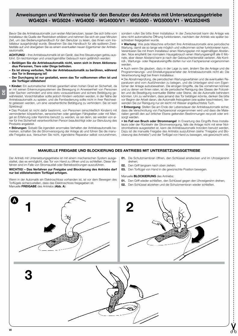
VI
DE
Anweisungen und Warnhinweise für den Benutzer des Antriebs mit Untersetzungsgetriebe WG4024 - WG5024 - WG4000 - WG4000/V1 - WG5000 - WG5000/V1 - WG3524HS
Bevor Sie die Antriebsautomatik zum ersten Mal benutzen, lassen Sie sich bitte vom Installateur die Quelle der Restrisiken erklären und nehmen Sie sich ein paar Minuten Zeit, um das Bedienungshandbuch für den Benutzer zu lesen, das Ihnen vom Ins-tallateur ausgehändigt wurde. Bewahren Sie das Handbuch für alle späteren Zwei-felsfälle auf und übergeben Sie es einem eventuellen neuen Eigentümer der Antrieb-sautomatik.
ACHTUNG! – Ihre Antriebsautomatik ist ein Gerät, das Ihre Steuerungen getreu aus-führt. Ein leichtsinniger und unsachgemäßer Gebrauch kann gefährlich werden:
– Betätigen Sie die Antriebsautomatik nicht, wenn sich in ihrem Aktionsra-dius Personen, Tiere oder Dinge befinden.
– Es ist streng verboten, Teile der Antriebsautomatik zu berühren, während das Tor in Bewegung ist!
– Der Durchgang ist nur gestattet, wenn das Tor vollkommen offen ist und die Torflügel stillstehen!
• Kinder: Ein automatischer Antrieb garantiert einen hohen Grad an Sicherheit, da er mit seinen Erkennungssystemen die Bewegung in Anwesenheit von Personen oder Sachen verhindert und eine stets voraussehbare und sichere Betätigung ge-währleistet. Vorsichtshalber sollte jedoch Kindern verboten werden, in der Nähe der Antriebsautomatik zu spielen, und die Fernbedienung sollte nicht in ihrer Reichwei-te gelassen werden, um eine versehentliche Betätigung zu verhindern: Sie ist kein Spielzeug!• Das Produkt ist nicht dafür bestimmt, von Personen (einschließlich Kindern) mit verminderten körperlichen, sensorischen oder geistigen Fähigkeiten oder mit Man-gel an Erfahrung oder Kenntnis benutzt zu werden, es sei denn, sie werden von ei-ner für ihre Sicherheit verantwortlichen Person beaufsichtigt oder zur Benutzung des Produkts angeleitet. • Störungen: Sobald Sie irgendein anormales Verhalten der Antriebsautomatik be-merken, schalten Sie die Stromversorgung der Anlage ab und führen Sie die manu-elle Freigabe aus. Versuchen Sie nicht, irgendeine Reparatur selbst vorzunehmen,
sondern rufen Sie bitte Ihren Installateur. In der Zwischenzeit kann die Anlage wie eine nicht automatische Öffnung funktionieren, nachdem der Antrieb wie später be-schrieben freigegeben wurde.• Wartung: Wie jede Maschine erfordert Ihre Antriebsautomatik eine periodische Wartung, damit sie so lange wie möglich und vollkommen sicher funktionieren kann. Vereinbaren Sie mit Ihrem Installateur einen Wartungsplan mit regelmäßigen Abstän-den. Nice empfiehlt bei normalem Hausgebrauch einen Wartungseingriff alle 6 Mo-nate, aber dieser Abstand kann je nach der Gebrauchsintensität variieren. Alle Kont-roll-, Wartungs- oder Reparatureingriffe dürfen nur von Fachpersonal vorgenommen werden.• Auch wenn Sie glauben, dazu in der Lage zu sein, ändern Sie die Anlage und die Programmierungs- und Einstellungsparameter der Antriebsautomatik nicht ab: Die Verantwortung liegt bei Ihrem Installateur.• Die Abnahmeprüfung, die periodischen Wartungsverfahren und die eventuellen Re-paraturen sind vom Ausführenden zu belegen, und die Unterlagen sind vom Eigen-tümer der Anlage aufzubewahren. Die einzigen Eingriffe, die Sie vornehmen können und zu denen wir Ihnen raten, ist die periodische Reinigung des Glases der Fotozel-len und die Beseitigung eventueller Blätter oder Steine, die die Automatik behindern könnten. Um zu verhindern, dass jemand das Tor betätigen könnte, denken Sie bitte vor Beginn der Arbeit daran, die Automatik freizugeben (wie später beschrieben), Ver-wenden Sie zur Reinigung nur ein leicht mit Wasser angefeuchtetes Tuch.• Entsorgung: Stellen Sie am Ende der Lebensdauer der Antriebsautomatik sicher, dass die Verschrottung von Fachpersonal vorgenommen wird und dass die Mate-rialien gemäß den auf örtlicher Ebene geltenden Bestimmungen recycelt oder ent-sorgt werden.• Im Fall von Bruch oder Strommangel: In Erwartung des Eingriffs Ihres Installa-teurs oder der Rückkehr der Stromversorgung, falls die Anlage nicht mit einer Not-strombatterie ausgestattet ist, kann die Antriebsautomatik trotzdem benutzt werden. Dazu ist die manuelle Freigabe des Antriebs auszuführen (siehe “Freigabe und Blo-ckierung des Antriebs”) und der Torflügel von Hand zu bewegen, wie gewünscht wird.
Der Antrieb mit Untersetzungsgetriebe ist mit einem mechanischen System ausge-stattet, das es ermöglicht, das Tor von Hand zu öffnen und zu schließen. Diese Ver-fahren sind im Falle von Stromausfall oder Betriebsstörungen auszuführen.
WICHTIG! – Das Verfahren zur Freigabe und Blockierung des Antriebs darf nur bei stillstehendem Torflügel erfolgen.
Wenn in der Automatik ein Elektroschloss vorhanden ist, ist vor dem Bewegen des Torflügels sicherzustellen, dass das Elektroschloss freigegeben ist.Manuelle FREIGABE des Antriebs (Abb. A):
MANUELLE FREIGABE UND BLOCKIERUNG DES ANTRIEBS MIT UNTERSETZUNGSGETRIEBE
01. Die Schutzmembran öffnen, den Schlüssel einstecken und im Uhrzeigersinn drehen;
02. Den Griff langsam nach oben ziehen;03. Den Torflügel von Hand in die gewünschte Position bewegen.
Manuelle BLOCKIERUNG des Antriebs:
01. Den Griff wieder schließen, den Schlüssel gegen den Uhrzeigersinn drehen;02. Den Schlüssel abziehen und die Schutzmembran wieder schließen.
1
3
2A

VII
PL
Instrukcje i ostrzeżenia przeznaczone dla użytkownika motoreduktoraWG4024 - WG5024 - WG4000 - WG4000/V1 - WG5000 - WG5000/V1 - WG3524HS
Przedpierwszymużyciemautomatu,zapytajciemontażystęopochodzenieryzykaszczątkowegoipoświęćciekilkaminutnaprzeczytanieinstrukcjiobsługiiostrzeżeńotrzymanychodmontażysty.Zachowajcieinstrukcjęnaprzyszłość,dowgląduprzykażdejewentualnejniepewności,wraziepotrzebyprzekażciejąnowemuwłaścicie-lowi automatu.
UWAGA!–Waszautomatjestmechanizmem,którydokładniewykonujewaszepo-lecenia;przyniepoprawnyminieodpowiedzialnymużyciumożebyćniebezpieczny:
– Nie zlecać ruchów gdy w zasięgu działania znajdują się osoby, zwierzęta lub rzeczy.
– Jest surowo zabronione dotykanie części automatu podczas gdy brama lub drzwi są w ruchu!
– Przejście jest dozwolony tylko gdy brama lub drzwi są całkowicie otwarte z zatrzymanymi skrzydłami!
• Dzieci:instalacjaautomatuzapewniawysokistopieńbezpieczeństwa,zabrania-jąc,dziękiczujnikom,jakichkolwiekruchówwobecnościosóblubrzeczyigwaran-tującprzewidywalnąibezpiecznaaktywację.Należyjednakzabronićdzieciomza-bawwpobliżuautomatu,abyzapobiegaćuaktywnieniuautomatu,niepozostawiaćpilotawichzasięgu:niejestzabawą!
•Produktniejestprzeznaczonydoużyciaprzezosoby(równieżdzieci)którychmoż-liwościfizyczne,zmysłoweipsychicznesąograniczone,lubprzezosobyzbrakiemdoświadczeniaorazznajomości,chybażezapośrednictwemosobyodpowiedzial-nejzaichbezpieczeństwo,podjejnadzoremlubpootrzymaniuinstrukcjidotyczą-cychużywaniaproduktu.
• Nieprawidłowości:Jaktylkozauważyciejakąkolwieknieprawidłowądziałalnośćautomatu,odetnijciezasilanieautomatyczneinstalacjiiwykonajcieręczneodbloko-wanie.Niepróbujciewykonywaćnapraw,zwróćciesięopomocdotechnika,któryzamontowałautomat:wmiędzyczasieinstalacjamożedziałaćjakonieautomatycz-ne otwarcie, po odblokowaniu motoreduktor jak opisano dalej.
• Konserwacja:Jakkażdamaszynawaszautomatwymagaokresowejkonserwacjidlajaknajdłuższegookresużywotnościicałkowitegobezpieczeństwa.Uzgodnijcieztechnikiemmontującymplanokresowejkonserwacji;Nicezalecaczynnościkonser-wacyjneco6miesięcyprzyprywatnymużyciu,tenokresmożesięzmieniaćwza-leżnościodczęstotliwościużycia.Jakakolwiekczynnośćkontrolna,konserwacjilubnaprawymusibyćwykonanaprzezwykwalifikowanypersonel.
•Nawetjeżeliwaszymzdaniemjesteściewstanie,niezmieniajcieinstalacjiiparame-trów zaprogramowania oraz regulacji automatu: odpowiedzialny jest technik mon-tujący.
•Próbatechniczna,okresowakonserwacjaiewentualnenaprawymusząbyćudo-kumentowaneprzezosobę,któraichdokonujeitakiedokumentysąprzechowywa-neprzezwłaścicielainstalacji.Jedyneczynnościktóremożeciewykonywaćizale-camyichokresowewykonywanie,toczyszczenieszkiełekfotokomórkiiusunięcieewentualnychliścilubkamieni,któremogąblokowaćautomat.Abyzabronićuru-chomieniabramyprzezinneosoby,podczaswykonywaniatychczynności,pamię-tajcieoodblokowaniuautomatu(jakopisanoponiżej)iużywajciedoczyszczeniaty-koszmatkizwilżonejwodą.
• Likwidacja:Pookresieżywotnościautomatu,upewnijciesię,czylikwidacjazosta-ławykonanaprzezwykwalifikowaneosobyi,żemateriałyzostanąodzyskanelubzli-kwidowanezgodniezlokalnieobowiązującymprawem.
• W przypadku zaniku lub braku zasilania:Woczekiwaniunazadziałaniewasze-gomontażystylubprzywrócenieenergiielektrycznej,jeżeliinstalacjaniejestwypo-sażonawbateriębuforową,automatmożebyćużywany.Należyręcznieodbloko-waćmotoreduktor(patrz“Odblokowanieizablokowaniemotoreduktora”)iręcznieprzesunąćskrzydłobramydożądanejpozycji.
Motoreduktorjestwyposażonywmechanicznysystem,którypozwalanaręczneotwarcieizamknięciebramy.Takieczynnościmusząbyćwykonywanewprzypad-kachblack-outelektrycznegolubnieprawidłowościfunkcjonowania.
WAŻNE! – Czynność odblokowania i zablokowania motoreduktora musi być wykonywana tylko gdy skrzydło jest nieruchome.
Jeżeliwautomaciejestobecnyelektrozamek,przedporuszeniemskrzydła,należyupewnićsię,czyjestonodblokowany.
RĘCZNE ODBLOKOWANIE I ZABLOKOWANIE MOTOREDUKTORA
ODBLOKOWANIE ręcznemotoreduktora(rys. A):
01. Przesunąćmembranęochronnąiwłożyćkluczprzekręcającgowkierunkuze-garowym;
02. Pociągnąćuchwytdogóry,towarzyszącmu;03. Wtymmomencie,przesunąćręcznieskrzydłobramydożądanejpozycji.
ZABLOKOWANIE ręcznemotoreduktora:
01. Zamknąćuchwytiprzekręcićkluczwkierunkuprzeciwnymdozegarowego02. Wyjąćkluczizamknąćmembranęochronną.
1
3
2A

VIII
NL
EN - Images
IT - Immagini
FR - Images
ES - Imágenes
DE - Bilder
PL - Zdjęcia
NL - Afbeeldingen
Instructies en aanwijzingen bestemd voor de gebruiker van de reductiemotorWG4024 - WG5024 - WG4000 - WG4000/V1 - WG5000 - WG5000/V1 - WG3524HS
Alvorens voor de eerste keer de automatisering te gebruiken, moet de installatie-technicus de oorsprong van de overblijvende risico’s uitleggen. Wijd enkele minuten aan het lezen van de instructiehandleiding en de aanwijzingen voor de klant. De in-stallatietechnicus zal u de handleiding leveren. Bewaar de handleiding voor elke toe-komstige twijfel en overhandig hem aan de eventuele nieuwe eigenaar van de au-tomatisering.
OPGEPAST! – Uw automatisering is een machine die op betrouwbare wijze uw be-velen uitvoert. Een onverantwoordelijk en oneigen gebruik kan de installatie ge vaarlijk maken:
– Beveel de verplaatsing van de automatisering niet indien in zijn werkings-veld personen, dieren of zaken aanwezig zijn.
– Het is strikt verboden delen van de automatisering aan te raken terwijl het hekwerk of de poort in beweging is!
– De doorgang is enkel toegelaten wanneer het hek of de poort volledig open is, met stilstaande vleugels!
• Kinderen: een automatisering garandeert een hoge veiligheidsgraad. De detec-teersystemen beletten de verplaatsing in aanwezigheid van personen of zaken. Een veilige en steeds voorzienbare activering is gegarandeerd. Hoe dan ook is het aa n-ge raden de kinderen te verbieden in de nabijheid van de automatisering te spelen. Om ongewenste activeringen te vermijden adviseren we de afstandsbediening niet binnen hun bereik te laten. Het is geen spel!• Het gebruik van het product is niet bestemd voor fysisch, sensorieel, of mentaal ge handicapten (met inbegrip van kinderen) of personen zonder ervaring of kennis, behalve indien ze door bemiddeling van een persoon, verantwoordelijk voor hun ze-kerheid, in aanmerking komen voor een begeleiding of instructies i.v.m. het ge bruik van het product.• Afwijking: Zodra een afwijking in de automatisering wordt opgemerkt, moet de elektrische voeding van de installatie afgesloten worden en een handmatige deblok-kering uitgevoerd worden. Probeer niet reparaties uit te voeren, maar neem contact op met uw installatietechnicus. Ondertussen kan de installatie werken met niet ge-
automatiseerde opening, eens de reductiemotor gedeblokkeerd werd, zoals verder wordt beschreven.• Onderhoud: Zoals elke machine heeft uw automatisering een regelmatig onder-houd nodig, zodat hij zo lang mogelijk meegaat en in perfecte veiligheid werkt. Be-spreek met uw installatietechnicus een onderhoudsplan met regelmatige frequentie. De firma Nice raadt aan bij een normaal gebruik om de 6 maanden een ingreep uit te voeren. Deze periode kan variëren in functie van de gebruiksintensiteit. Om het even welke controle-, onderhoud- of herstellingsingreep mag enkel uitgevoerd wor-den door bevoegd personeel.• Ook al denkt u hiervoor bevoegd te zijn, mag u nooit de installatie, de program-ma- en afstellingsparameters van de automatisering wijzigen: de installatietechnicus is hiervoor verantwoordelijk.• De testen, het regelmatig onderhoud en de eventuele reparaties moeten gedocu-menteerd worden door de uitvoerders en de documenten moeten door de eigenaar van de installatie bewaard worden. De enige ingrepen die u wel kunt uitvoeren en die we sterk aanbevelen regelmatig uit te voeren, is het schoonmaken van het glas van de fotocellen en het verwijderen van eventuele bladeren of stenen die de automatise-ring zouden kunnen belemmeren. Om te beletten dat iemand het hekwerk zou kun-nen op gang brengen, moet u alvorens te werk te gaan, de automatisering deblok-keren (zoals verder beschreven). Gebruik voor het schoonmaken enkel een doek, een weinig bevochtigd met water.• Verwijdering: Op het einde van de levensduur van de automatisering moet u zich ervan verzekeren dat de ontmanteling uitgevoerd wordt door bevoegd personeel en dat de materialen gerecycleerd of verwijderd worden volgens de van kracht zijnde normen in het land van gebruik.• Bij stukgaan of bij afwezigheid van voeding: In afwachting van een ingreep van uw installatietechnicus of tot de elektrische stroom terugkeert en indien de in-stallatie niet van een batterij is voorzien, kan de automatisering toch worden ge-bruikt. De manuele deblokkering van de reductiemotor moet worden uitgevoerd (zie “deblokkeren en blokkeren van de reductiemotor”) en de vleugel van het hekwerk kan handmatig naar wens bewogen worden.
De reductiemotor is voorzien van een mechanisch systeem dat toelaat het hek ma-nueel te openen en te sluiten. Deze handelingen moeten uitgevoerd worden bij een elektrische black-out of afwijkingen in de werking.
BELANGRIJK! – De deblokkering en blokkering van de reductiemotor mag slechts uitgevoerd worden wanneer de vleugels stil staan.
Indien in de automatisering een elektrisch slot aanwezig is, moet u alvorens de vleu-gel te verplaatsen, u ervan verzekeren dat het elektrische slot gedeblokkeerd is.
MANUEEL DEBLOKKEREN EN BLOKKEREN VAN DE REDUCTIEMOTOR
DEBLOKKEER manueel de reductiemotor (afb. A):
01. Verschuif het beschermende membraan en voeg de sleutel in. Draai hem met de wijzers van de klok mee.
02. Trek de handgreep naar boven, zonder hem los te laten.03. Verplaats nu manueel de vleugel van het hek in de gewenste stand.
BLOKKEER manueel de reductiemotor:
01. Sluit de handgreep en draai de sleutel tegen de wijzers van de klok in.02. Verwijder de sleutel en sluit het beschermend membraan.
1
3
2A

EN - Images
IT - Immagini
FR - Images
ES - Imágenes
DE - Bilder
PL - Zdjęcia
NL - Afbeeldingen
IX
EN
ITFR
ES
DE
PL
NL

X
NL
PL
DE
ES
FRIT
EN
0,5
Kg 500
450
400
350
300
250
200
150
100
50
0
1 1,5 2
B
A
2,5 3 3,5 m
WG5024 - WG5000 - WG5000/V1
0,5
Kg 200
175
150
125
100
75
50
25
0
1 1,5 2
B
A
2,5 3 m
WG3524HS
0,5
Kg 400
350
300
250
200
150
100
50
0
1 1,5
B
A
2 m
WG4024 - WG4000 - WG4000/V1
EN GRAPH 1 “Limits of use of the product”
IT GRAFICO 1 “Limiti d’impiego del prodotto”
FR GRAPHIQUE 1 “Limites d’utilisation du produit”
ES GRÁFICO 1 “Límites de empleo del producto”
DE GRAPHIK 1 “Verwendungsgrenzen des Produkts”
PL SCHEMAT 1 “Ograniczenia używania produktu”
NL GRAFIEK 1 “Gebruiksbeperkingen van het product”
kg:
EN Maximum weight of the gate leaf
IT Peso massimo dell’anta del cancello
FR Poids maximum du vantail du portail
ES Peso máximo de la hoja de la puerta
DE Höchstgewicht des Torflügels
PL Ciężar maksymalny skrzydła bramy
NL Maximum gewicht van de vleugel van het hekwerk
m:
EN Maximum length of the gate leaf
IT Lunghezza massima dell’anta del cancello
FR Longueur maximum du vantail du portail
ES Longitud máxima de la hoja de la puerta
DE Höchstlänge des Torflügels
PL Długość maksymalna skrzydła bramy
NL Maximum lengte van de vleugel van het hekwerk

XI
EN
ITFR
ES
DE
PL
NL
A (mm)
C B 90° ÷ 100°
100° ÷ 110°
110° ÷ 120°
120° ÷ 130°
(mm
) r. i. l
. recommendedinstallation line
WG4024 - WG4000 - WG4000/V1
recommendedinstallation line
A (mm)
C B...° ÷ 90°
91° ÷ 100°
101° ÷ 110°
111° ÷ 120°
(mm
)
r. i. l
.
WG5024 - WG5000 - WG5000/V1 - WG3524HS
EN GRAPH 2
IT GRAFICO 2
FR GRAPHIQUE 2
ES GRÁFICO 2
DE GRAPHIK 2
PL SCHEMAT 2
NL GRAFIEK 2

XII
NL
PL
DE
ES
FRIT
EN 1
a
b c d
e
d
2
WG4024 - WG4000 - WG4000/V1
98 mm
770 mm
320 mm
WG5024 - WG5000 - WG5000/V1 - WG3524HS
98 mm
920 mm
470 mm
95 mm
95mm

XIII
EN
ITFR
ES
DE
PL
NL
DD
3
AA
B B
FG
DD
CC
E
E4
A
D
BC

XIV
NL
PL
DE
ES
FRIT
EN 6
A (mm)
C B 90° ÷ 100°
100° ÷ 110°
110° ÷ 120°
120° ÷ 130°
90° ÷ 100°
100° ÷ 110°
110° ÷ 120°
120° ÷ 130°
110° ÷ 120°
130
130
5
7
D
AE
B
C

XV
EN
ITFR
ES
DE
PL
NL
F
WG4024 - WG4000 - WG4000/V1: F = 30 mm
WG5024 - WG5000 - WG5000/V1 - WG3524HS : F = 30 mm
8
9

XVI
NL
PL
DE
ES
FRIT
EN
90 mm max
10
11

XVII
EN
ITFR
ES
DE
PL
NL
12 13
1
3
214