Embed Size (px)
Citation preview

BEDIENUNGSANLEITUNGBEDIENUNGSANLEITUNGBEDIENUNGSANLEITUNGBEDIENUNGSANLEITUNGUSER'S MANUALUSER'S MANUALUSER'S MANUALUSER'S MANUALMODE D'EMPLOIMODE D'EMPLOIMODE D'EMPLOIMODE D'EMPLOI
MANUAL DEL USUARIOMANUAL DEL USUARIOMANUAL DEL USUARIOMANUAL DEL USUARIO
PM-524Pro-Mixer
© COPYRIGHTNachdruck verboten!All rights reserved!Réproduction interdite!Prohibida toda reproducción!
Für weiteren Gebrauch aufbewahren!Keep this manual for further needs!
Gardez ces instructions pour des utilisations ultérieurs!Guarde este manual para posteriores usos.
-30 dBMIN (FX)
+15 dBMAX (FX)
-30 dBMIN (FX)
+15 dBMAX (FX)
GAIN
TREBLE
MIDDLE
BASS
TALKOVER
GAIN GAIN
BOOTH
BALANCE
MASTER
MIC 1
CUEMIX
CUESPLIT
10
5
0
10
5
0
10
5
0
10
5
0
10
5
0
10
5
0
CUE MIXING
CUE PGM
CUE PGM
HEADPHONES
POWER
CUE LEVEL
ON
OFF
CROSSFADER
CH-1/CH-2 CH-3
PM-524Pro-Mixer
CH-1 CH-2 CH-3
0 10
MIN (KILL) MAX (FX) MIN (KILL) MAX (FX)
MIN MAX MIN MAX
0 10MIN (KILL) MAX (FX)
MIN MAX
L R
0 10
MIN (KILL) MAX (FX)MIN (KILL) MAX (FX)MIN (KILL) MAX (FX)
-30 dBMIN (FX)
+15 dBMAX (FX)
OMNITRONIC
PHONO 1 LINE 1 MIC 1 PHONO 2 LINE 2 MIC 2 PHONO 3 LINE 3 MIC 3
CROSSFADER ASSIGN
CH-1
CH-2
TREBLE
MIDDLE
BASS
TREBLE
MIDDLE
BASS
BEAT BEAT
10 5 0
0 5 10
CUE CUECUE
12 V LAMPMAX 120 mA
MASTER LEVEL
CUE LEVEL
– 20 15 10 7 5 3 1 0 1 3 5 8 +
– 20 15 10 7 5 3 1 0 1 3 5 8 +
L L
L+R L+R
R R12
3
RECMASTER BOOTH
OUTPUT
CAUTIONRead manual before use.
To prevent electrical fire and shock hazard, do not expose this applianceto moisture. Risk of electric shock! Do not open! Disconnect from mains
before changing fuse. Replace the fuse only with the same type and rating.Vor Gebrauch Anleitung lesen.
Gerät vor Feuchtigkeit schützen. Bei Sicherungswechsel Netzstecker ziehen!Nur Sicherungen mit gleichen Leistungswerten einsetzen.
Lire le mode d’emploi avant l’utilisation.Afin de prévenir tous risques d’électrocution et de court-circuits, ne pas exposer
à l’humidité. Débrancher avant de remplacer le fusible.Utiliser un fusible de rechange de même type.
Gefahr! Gerät nicht öffnen!
Attention! Ne pas ouvrir le boîtier!
GNDMIC 2MIC 3
LINE 3 PHONO 3 LINE 2 PHONO 2
CH-3 CH-2 CH-1
LINE 1 PHONO 1
L
R
L
R
AC INPUT 115/230 V, 50/60 Hz
115
FUSE F 0.5 A, 250 V
VOLTAGESELECTOR
230
www.omnitronic.com
OMNITRONIC®
Typ/Type:Spannungsversorgung/Power supply:
Gesamtanschlusswert/Powerconsumption:
Sicherung/Fuse:
OMNITRONIC PM-524 EL
115/230 V AC, 50/60 Hz ~
30 WF 0,5 A, 250 V
OMNITRONIC SHOWEQUIPMENT GmbH, GERMANY
Frontpanel
Rearpanel
REC
MA
STER
BO
OTH
OU
TPU
T
CA
UT
ION
Re
ad
ma
nu
alb
efo
r eu
se
.To
pre
ve
nt
ele
ctr
ica
lfi
r ea
nd
sh
oc
kh
aza
r d,d
on
ot
ex
po
se
this
ap
plia
nc
eto
mo
istu
re.R
isk
of
ele
ctr
icsh
oc
k!D
on
ot
op
en
!D
isc
on
ne
ct
fro
mm
ain
sb
efo
rec
ha
ng
ing
fuse
.R
ep
lac
eth
efu
se
on
lyw
ith
the
sa
me
typ
ea
nd
rati
ng
.V
or
Ge
bra
uc
hA
nle
itu
ng
lese
n.
Ge
rät
vo
rF
eu
ch
tig
ke
itsc
hü
tze
n.B
eiS
ich
eru
ng
sw
ec
hse
lN
etz
ste
ck
er
zie
he
n!
Nu
rS
ich
eru
ng
en
mit
gle
ich
en
Le
istu
ng
sw
er t
en
ein
se
tze
n.
Lir
ele
mo
de
d’e
mp
loia
va
nt
l ’u
tilisa
tio
n.
Afi
nd
ep
réve
nir
tou
sri
sq
ue
sd
’éle
ctr
oc
uti
on
et
de
co
ur t
-cir
cu
its,n
ep
as
ex
po
se
rà
l’h
um
idit
é.
Dé
bra
nc
he
ra
va
nt
de
r em
pla
ce
rle
fusib
le.
Uti
lise
ru
nfu
sib
led
er e
ch
an
ge
de
mê
me
typ
e.
Ge
fah
r!G
erä
tn
ich
tö
f fn
en
!
Att
en
tio
n!N
ep
as
ou
vri
rle
bo
îtie
r!
GN
DM
IC2
MIC
3
LIN
E3
PH
ON
O3
LIN
E2
PH
ON
O2
CH
-3C
H-2
CH
-1
LIN
E1
PH
ON
O1
L R
L R
AC
INPU
T1
15
/23
0V,
50
/60
Hz
11
5
FUSE
F0
.5A
,2
50
V
VO
LTA
GE
SEL
ECTO
R
23
0
ww
w.o
mn
itro
nic
.co
m
OM
NIT
RO
NIC
®
Typ
/Typ
e:
Sp
ann
un
gsve
rso
rgu
ng/
Po
wer
sup
ply
:
Gesa
mta
nsc
hlu
ssw
ert
/Po
wer
con
sum
pti
on
:Sic
heru
ng/
Fuse
:
OM
NIT
RO
NIC
PM
-52
4EL
11
5/2
30
VA
C,5
0/6
0H
z~
30
WF
0,5
A,2
50
V
OM
NIT
RO
NIC
SH
OW
EQ
UIP
MEN
TG
mb
H,G
ERM
AN
Y
1B
IT8
TIM
ESO
VER
SA
MPLI
NG
D/A
CO
NV
ERTER
CO
MP A
CT
DIS
CPLA
YER
CO
MP
AC
T
DIG
ITA
LA
UD
IO
1
CDP-
744
Dua
l CD
-Pla
yer
OPEN
/CL O
SE
PO
WER
1B
IT8
TIM
ESO
VER
SA
MPLI
NG
D/A
CO
NV
ERTER
CO
MP A
CT
DIS
CPLA
YER
CO
MP
AC
T
DIG
ITA
LA
UD
IO
2
OM
NIT
RO
NIC
12
CDP-
744
Dua
l CD
-Pla
yer
0%
+1
2%
–12
%
PIT
CH
REL
OO
P
TIM
E/R
AN
DO
M
PIT
CH
REV
-FW
D+
CU
E
_
_
__
OPEN
/CL O
SE
DIS
C1
DIS
C2
REL
AY
OM
NIT
RO
NIC
CU
E
_
_
__
21
34
65
78
9D
ISC
10
DIS
C2
OPEN
/CL O
SE
AU
TO
/NO
R
REV
-FW
D+
0%
+1
2%
–12
%
PIT
CH
REL
OO
P
OU
T/E
XIT
LOO
PIN
OU
T/E
XIT
LOO
PIN
TIM
E/R
AN
DO
M
PIT
CH
SH
UTTLE
/SC
AN
JOG
/SEA
RC
HSH
UTTLE
/SC
AN
JOG
/SEA
RC
H
–+
–+
12
27:56:12
REMAIN
04
123
456789
__
18:12:05
REMAIN
02
123
456789
__
__
1B
IT8
TIM
ESO
VER
SA
MPLI
NG
D/A
CO
NV
ERTER
CO
MP A
CT
DIS
CPLA
YER
CO
MP
AC
T
DIG
ITA
LA
UD
IO
1
CDP-
744
Dua
l CD
-Pla
yer
OPEN
/CL O
SE
PO
WER
1B
IT8
TIM
ESO
VER
SA
MPLI
NG
D/A
CO
NV
ERTER
CO
MP A
CT
DIS
CPLA
YER
CO
MP
AC
T
DIG
ITA
LA
UD
IO
2
OM
NIT
RO
NIC
12
CDP-
744
Dua
l CD
-Pla
yer
0%
+1
2%
–12
%
PIT
CH
REL
OO
P
TIM
E/R
AN
DO
M
PIT
CH
REV
-FW
D+
CU
E
_
_
__
OPEN
/CL O
SE
DIS
C1
DIS
C2
REL
AY
OM
NIT
RO
NIC
CU
E
_
_
__
21
34
65
78
9D
ISC
10
DIS
C2
OPEN
/CL O
SE
AU
TO
/NO
R
REV
-FW
D+
0%
+1
2%
–12
%
PIT
CH
REL
OO
P
OU
T/E
XIT
LOO
PIN
OU
T/E
XIT
LOO
PIN
TIM
E/R
AN
DO
M
PIT
CH
SH
UTTLE
/SC
AN
JOG
/SEA
RC
HSH
UTTLE
/SC
AN
JOG
/SEA
RC
H
–+
–+
12
27:56:12
REMAIN
04
123
456789
__
18:12:05
REMAIN
02
123
456789
__
__
Co
nn
ect
wit
hm
ain
s
Cas
sett
eD
eck,
DA
T-R
eco
rder
,et
c.
CD
-Pla
yer
2C
D-P
laye
r1
Mic
rop
ho
ne
2
Mic
rop
ho
ne
3
Tap
eR
eco
rder
,C
asse
tte
Dec
k,et
c.
Am
plif
ier
2
Am
plif
ier
1
Sp
eake
r-sy
stem
2
Sp
eake
r-sy
stem
1
Turn
tab
le2
Turn
tab
le1
Turn
tab
le3
STA
RT/S
TOP
33
45
OFF
ON
PO
WER
PIT
CH
+/-
20
%Q
UA
RTZ
LOC
KPIT
CH
+/-
10
%D
D-3
220
Prof
essi
onal
Hig
hT o
rque
Dir
ect-
Dri
veT u
rnta
ble
OM
NIT
RO
NIC
HEI
GH
T
0
1
0,5
1,0
1,5
2,0
STA
RT/S
TOP
33
45
OFF
ON
PO
WER
PIT
CH
+/-
20
%Q
UA
RTZ
LOC
KPIT
CH
+/-
10
%D
D-3
220
Prof
essi
onal
Hig
hT o
rque
Dir
ect-
Dri
veT u
rnta
ble
OM
NIT
RO
NIC
HEI
GH
T
0
1
0,5
1,0
1,5
2,0
STA
RT/S
TOP
33
45
OFF
ON
PO
WER
PIT
CH
+/-
20
%Q
UA
RTZ
LOC
KPIT
CH
+/-
10
%D
D-3
220
Prof
essi
onal
Hig
hT o
rque
Dir
ect-
Dri
veT u
rnta
ble
OM
NIT
RO
NIC
HEI
GH
T
0
1
0,5
1,0
1,5
2,0
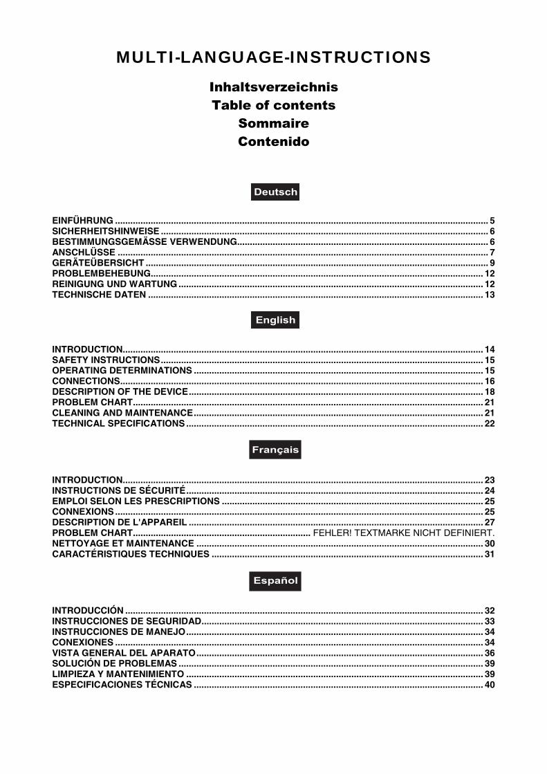
MULTI-LANGUAGE-INSTRUCTIONS
InhaltsverzeichnisTable of contents
SommaireContenido
EINFÜHRUNG ................................................................................................................................................... 5SICHERHEITSHINWEISE ................................................................................................................................. 6BESTIMMUNGSGEMÄSSE VERWENDUNG................................................................................................... 6ANSCHLÜSSE .................................................................................................................................................. 7GERÄTEÜBERSICHT ....................................................................................................................................... 9PROBLEMBEHEBUNG................................................................................................................................... 12REINIGUNG UND WARTUNG ........................................................................................................................ 12TECHNISCHE DATEN .................................................................................................................................... 13
INTRODUCTION.............................................................................................................................................. 14SAFETY INSTRUCTIONS............................................................................................................................... 15OPERATING DETERMINATIONS .................................................................................................................. 15CONNECTIONS............................................................................................................................................... 16DESCRIPTION OF THE DEVICE.................................................................................................................... 18PROBLEM CHART.......................................................................................................................................... 21CLEANING AND MAINTENANCE.................................................................................................................. 21TECHNICAL SPECIFICATIONS ..................................................................................................................... 22
INTRODUCTION.............................................................................................................................................. 23INSTRUCTIONS DE SÉCURITÉ..................................................................................................................... 24EMPLOI SELON LES PRESCRIPTIONS ....................................................................................................... 25CONNEXIONS ................................................................................................................................................. 25DESCRIPTION DE L'APPAREIL .................................................................................................................... 27PROBLEM CHART...................................................................... FEHLER! TEXTMARKE NICHT DEFINIERT.NETTOYAGE ET MAINTENANCE ................................................................................................................. 30CARACTÉRISTIQUES TECHNIQUES ........................................................................................................... 31
INTRODUCCIÓN ............................................................................................................................................. 32INSTRUCCIONES DE SEGURIDAD............................................................................................................... 33INSTRUCCIONES DE MANEJO..................................................................................................................... 34CONEXIONES ................................................................................................................................................. 34VISTA GENERAL DEL APARATO................................................................................................................. 36SOLUCIÓN DE PROBLEMAS ........................................................................................................................ 39LIMPIEZA Y MANTENIMIENTO ..................................................................................................................... 39ESPECIFICACIONES TÉCNICAS .................................................................................................................. 40
14
OPERATING INSTRUCTIONS
PM-524 Pro-MixerCAUTION!
Keep this device away from rain and moisture!Unplug mains lead before opening the housing!
For your own safety, please read this user manual carefullybefore you initial start-up.
All persons involved in the installation, operation and maintenance of this device have to:- be qualified- follow the instructions of this manual
INTRODUCTIONThank you for having chosen a OMNITRONIC PM-524. If you follow the instructions given in this manual, wecan assure you that you will enjoy this device for many years.
Unpack your OMNITRONIC PM-524.
Please make sure that there are no obvious transport damages. Should you notice any damages on the A/Cconnection cable or on the casing, do not take the device into operation and immediately consult your localdealer.
Features
Professional 3-channel mixerChannels 1-3 on the frontpanel switchable between phono, line or mic • Mic 1 microphone-input viaunbalanced XLR-socket on the frontpanel • Mic 2 and Mic 3 microphone-input via 1/4" mono-jack on therearpanel • Input-sensitivity-control (gain) for each channel • 3-fold, separate tone-control (bass, middle,treble) for each channel with extremely wide range • Killfunction (attenuated to -30 dB) and F/X-function(enforced to +15 dB) possible • High-quality and super-smooth ALPS-channel-faders • Super-smooth ALPS-crossfader replaceable from above • Crossfader for mixing channel 1, 2 and 3 (Crossfader Assign-button) • 2beat-indicators at the crossfader for perfect mixing • 3 LED-level-displays (master-out L/R and Cue Level) •Headphones-connection on the frontpanel • Headphones-output adjustable via Cue Level-control • AdditionalCue Split/Cue Mix-button • Cue Split-function: the Cue-signal is on the one side of the headphones and theoutput-signal on the other side • Cue Mix-function: the adjustable mix of Cue-signal and output-signal is onboth sides of the headphones • Mixing of the headphones-signal possible via cue mixing-fader • Outputsignal adjustable via master-control and balance-control • Master-Out, Booth-Out and Rec-Out via 2 RCA-sockets each • Rec-Out independent from Master-level for records with static level • Separately controllablemonitor-output (DJ-booth) for connecting active-speakers or an additional amplifier • High-grade multi-function-mixer with a convincing sound
The Kill-function makes it possible for you to cut the signal almost completely off by turning the control to theleft.
15
SAFETY INSTRUCTIONS
CAUTION!Be careful with your operations. With a dangerous voltage you can suffer a dangerouselectric shock when touching the wires!
This device has left our premises in absolutely perfect condition. In order to maintain this condition and toensure a safe operation, it is absolutely necessary for the user to follow the safety instructions and warningnotes written in this user manual.
Important:Damages caused by the disregard of this user manual are not subject to warranty. The dealer willnot accept liability for any resulting defects or problems.
Always plug in the power plug least. Make sure that the power-switch is set to OFF position before youconnect the device to the mains.
Keep away from heaters and other heating sources!
If the device has been exposed to drastic temperature fluctuation (e.g. after transportation), do not switch iton immediately. The arising condensation water might damage your device. Leave the device switched offuntil it has reached room temperature.
Never put any liquids on the device or close to it. Should any liquid enter the device nevertheless, disconnectfrom mains immediately. Please let the device be checked by a qualified service technician before youoperate it again. Any damages caused by liquids having entered the device are not subject to warranty!
This device falls under protection-class II and features a protective insulation.
Never let the power-cord come into contact with other cables! Handle the power-cord and all connectionswith the mains with particular caution!
Make sure that the available voltage is not higher than stated on the AC voltage selector.
Make sure that the power-cord is never crimped or damaged by sharp edges. Check the device and thepower-cord from time to time.
Always disconnect from the mains, when the device is not in use or before cleaning it. Only handle thepower-cord by the plug. Never pull out the plug by tugging the power-cord.
Before the device is switched on all faders and volume controls have to be set to "0" or "min" position.
CAUTION: Turn the amplifier on last and off first!
Keep away children and amateurs!
CAUTION: High volumes can cause hearing damage!
There are no serviceable parts inside the device. Maintenance and service operations are only to be carriedout by authorized dealers.
OPERATING DETERMINATIONSThis device is a professional audio-mixer for mixing audio-signals from different music-sources with oneanother. This product is allowed to be operated with an alternating current of 115/230 V, 50/60 Hz and wasdesigned for indoor use only.
Do not shake the device. Avoid brute force when installing or operating the device.
16
When choosing the installation-spot, please make sure that the device is not exposed to extreme heat,moisture or dust. There should not be any cables lying around. You endanger your own and the safety ofothers!
Do not operate the device in extremely hot (more than 30° C) or extremely cold (less than 5° C)surroundings. Keep away from direct insulation (particularly in cars) and heaters.
Operate the device only after having familiarized with its functions. Do not permit operation by persons notqualified for operating the device. Most damages are the result of unprofessional operation!
Never use spray cleaners in order to clean the faders!
Never use solvents or aggressive detergents in order to clean the device! Rather use a soft and damp cloth.
Please use the original packaging if the device is to be transported.
Never remove the serial barcode from the device as this would make the guarantee void.
If this device will be operated in any way different to the one described in this manual, the product may sufferdamages and the guarantee becomes void. Furthermore, any other operation may lead to dangers like short-circuit, burns, electric shock, etc.
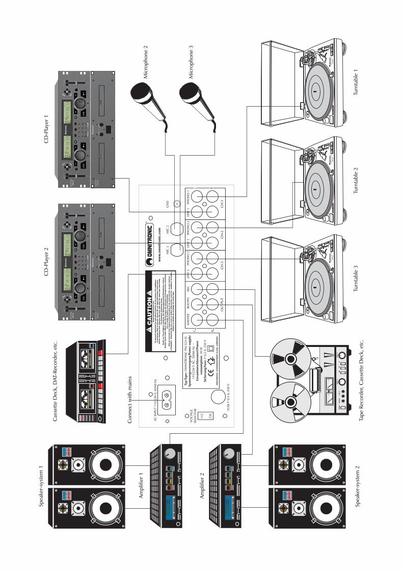
CONNECTIONS• Make sure that the power switch is set to "OFF". Before you connect the devices, all units have to beswitched off and the master-control is set to "0".
• Make sure that the available voltage is not higher than stated on the voltage selector before you connectthe power-cord.
• In order to obtain highest sound-quality, only use high-quality cables for connecting the devices. Make surethat the cables are properly fixed.
• You can connect up to 2 amplifiers to the PM-524. The output signal of the Master-signal can be adjustedvia the Master-control and the Balance-control. The output-signal of the Booth-signal can be adjusted via theBooth-control.
• The Master-output can be connected via the RCA-sockets. Make sure that the sockets are set properly(L & R).
• Via the BOOTH sockets, you can either connect active monitor-speakers for the DJ-booth or an additionalamplifier for creating a second zone.
• For recording, connect your tape recorder or cassette deck to the REC OUT-sockets. The REC OUT levelwill not be influenced by the master-control. You can set the output level with the channel faders, the tonecontrols and the GAIN control.
•The MIC 1 microphone can be connected via the XLR mounting-socket on the frontpanel. With theTalkover-button, you can attenuate the level of all other signal-sources without affecting the microphonevolume. You can adjust the microphone volume using the CH-1 fader. Make sure that thePHONO/LINE/MIC-switch is set to MIC.
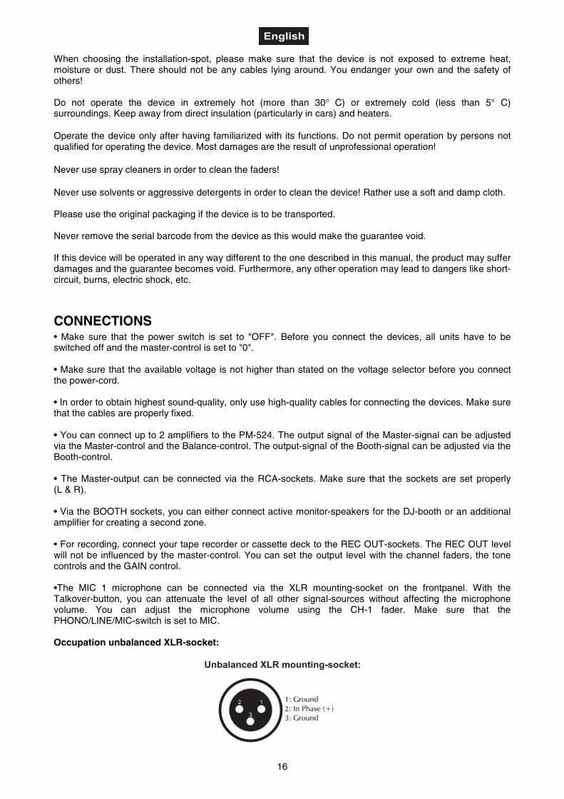
Occupation unbalanced XLR-socket:
Unbalanced XLR mounting-socket:
1: Ground2: In Phase (+)3: Ground
12
3
17
• Additionally, the PM-524 features two more ¼" MIC 2 and MIC 3 jack-sockets on the rearpanel. You canadjust the microphone volume using the CH-2 and CH-3 fader. Make sure that the PHONO/LINE/MIC-switchis set to MIC.
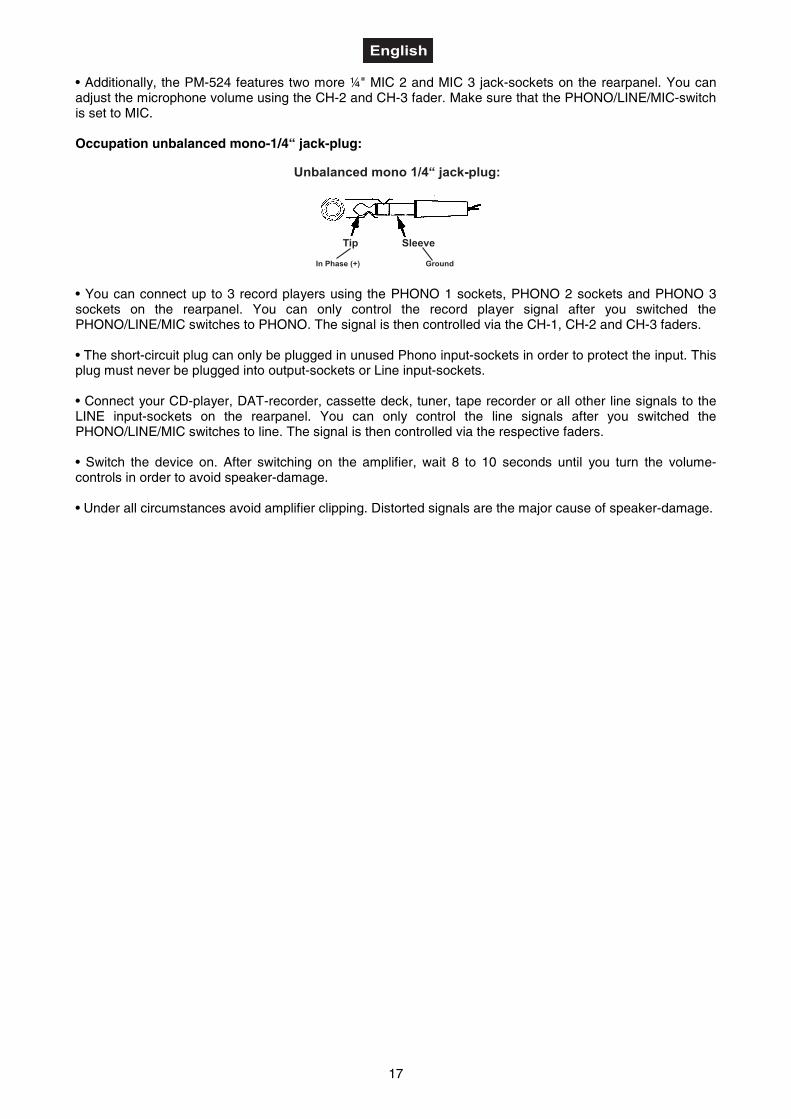
Occupation unbalanced mono-1/4“ jack-plug:
• You can connect up to 3 record players using the PHONO 1 sockets, PHONO 2 sockets and PHONO 3sockets on the rearpanel. You can only control the record player signal after you switched thePHONO/LINE/MIC switches to PHONO. The signal is then controlled via the CH-1, CH-2 and CH-3 faders.
• The short-circuit plug can only be plugged in unused Phono input-sockets in order to protect the input. Thisplug must never be plugged into output-sockets or Line input-sockets.
• Connect your CD-player, DAT-recorder, cassette deck, tuner, tape recorder or all other line signals to theLINE input-sockets on the rearpanel. You can only control the line signals after you switched thePHONO/LINE/MIC switches to line. The signal is then controlled via the respective faders.
• Switch the device on. After switching on the amplifier, wait 8 to 10 seconds until you turn the volume-controls in order to avoid speaker-damage.
• Under all circumstances avoid amplifier clipping. Distorted signals are the major cause of speaker-damage.
18
DESCRIPTION OF THE DEVICE
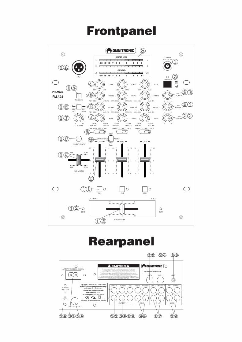
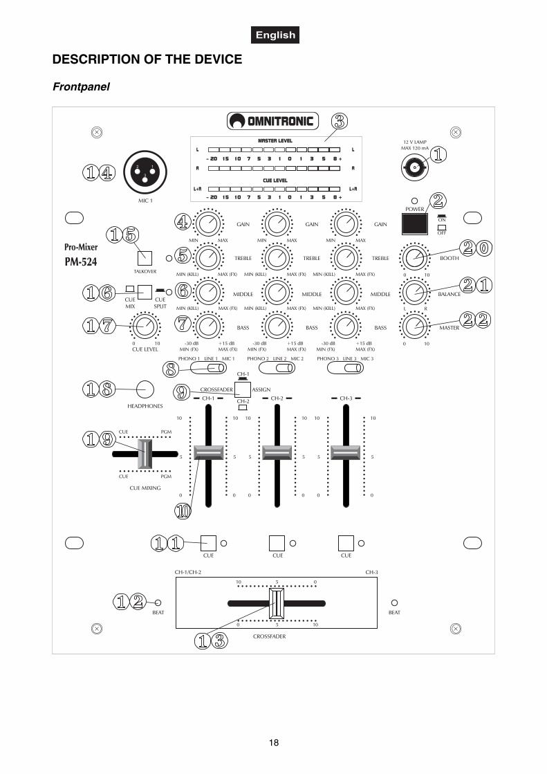
Frontpanel
-30 dBMIN (FX)
+15 dBMAX (FX)
-30 dBMIN (FX)
+15 dBMAX (FX)
GAIN
TREBLE
MIDDLE
BASS
TALKOVER
GAIN GAIN
BOOTH
BALANCE
MASTER
MIC 1
CUEMIX
CUESPLIT
10
5
0
10
5
0
10
5
0
10
5
0
10
5
0
10
5
0
CUE MIXING
CUE PGM
CUE PGM
HEADPHONES
POWER
CUE LEVEL
ON
OFF
CROSSFADER
CH-1/CH-2 CH-3
PM-524Pro-Mixer
CH-1 CH-2 CH-3
0 10
MIN (KILL) MAX (FX) MIN (KILL) MAX (FX)
MIN MAX MIN MAX
0 10MIN (KILL) MAX (FX)
MIN MAX
L R
0 10
MIN (KILL) MAX (FX)MIN (KILL) MAX (FX)MIN (KILL) MAX (FX)
-30 dBMIN (FX)
+15 dBMAX (FX)
OMNITRONIC
PHONO 1 LINE 1 MIC 1 PHONO 2 LINE 2 MIC 2 PHONO 3 LINE 3 MIC 3
CROSSFADER ASSIGN
CH-1
CH-2
TREBLE
MIDDLE
BASS
TREBLE
MIDDLE
BASS
BEAT BEAT
10 5 0
0 5 10
CUE CUECUE
12 V LAMPMAX 120 mA
MASTER LEVEL
CUE LEVEL
– 20 15 10 7 5 3 1 0 1 3 5 8 +
– 20 15 10 7 5 3 1 0 1 3 5 8 +
L L
L+R L+R
R R12
3
19
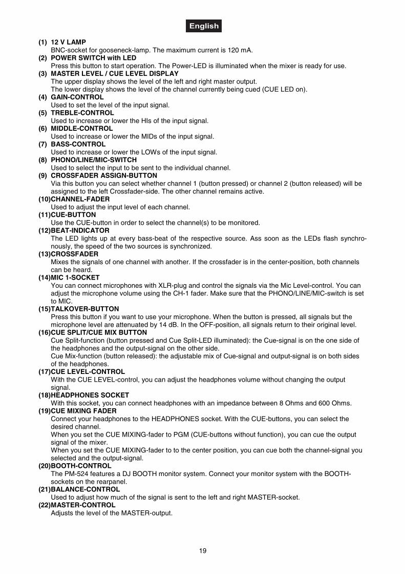
(1) 12 V LAMPBNC-socket for gooseneck-lamp. The maximum current is 120 mA.
(2) POWER SWITCH with LEDPress this button to start operation. The Power-LED is illuminated when the mixer is ready for use.
(3) MASTER LEVEL / CUE LEVEL DISPLAYThe upper display shows the level of the left and right master output.The lower display shows the level of the channel currently being cued (CUE LED on).
(4) GAIN-CONTROLUsed to set the level of the input signal.
(5) TREBLE-CONTROLUsed to increase or lower the HIs of the input signal.
(6) MIDDLE-CONTROLUsed to increase or lower the MIDs of the input signal.
(7) BASS-CONTROLUsed to increase or lower the LOWs of the input signal.
(8) PHONO/LINE/MIC-SWITCHUsed to select the input to be sent to the individual channel.
(9) CROSSFADER ASSIGN-BUTTONVia this button you can select whether channel 1 (button pressed) or channel 2 (button released) will beassigned to the left Crossfader-side. The other channel remains active.
(10) CHANNEL-FADERUsed to adjust the input level of each channel.
(11) CUE-BUTTONUse the CUE-button in order to select the channel(s) to be monitored.
(12) BEAT-INDICATORThe LED lights up at every bass-beat of the respective source. Ass soon as the LEDs flash synchro-nously, the speed of the two sources is synchronized.
(13) CROSSFADERMixes the signals of one channel with another. If the crossfader is in the center-position, both channelscan be heard.
(14) MIC 1-SOCKETYou can connect microphones with XLR-plug and control the signals via the Mic Level-control. You canadjust the microphone volume using the CH-1 fader. Make sure that the PHONO/LINE/MIC-switch is setto MIC.
(15) TALKOVER-BUTTONPress this button if you want to use your microphone. When the button is pressed, all signals but themicrophone level are attenuated by 14 dB. In the OFF-position, all signals return to their original level.
(16) CUE SPLIT/CUE MIX BUTTONCue Split-function (button pressed and Cue Split-LED illuminated): the Cue-signal is on the one side ofthe headphones and the output-signal on the other side.Cue Mix-function (button released): the adjustable mix of Cue-signal and output-signal is on both sidesof the headphones.
(17) CUE LEVEL-CONTROLWith the CUE LEVEL-control, you can adjust the headphones volume without changing the outputsignal.
(18) HEADPHONES SOCKETWith this socket, you can connect headphones with an impedance between 8 Ohms and 600 Ohms.
(19) CUE MIXING FADERConnect your headphones to the HEADPHONES socket. With the CUE-buttons, you can select thedesired channel.When you set the CUE MIXING-fader to PGM (CUE-buttons without function), you can cue the outputsignal of the mixer.When you set the CUE MIXING-fader to to the center position, you can cue both the channel-signal youselected and the output-signal.
(20) BOOTH-CONTROLThe PM-524 features a DJ BOOTH monitor system. Connect your monitor system with the BOOTH-sockets on the rearpanel.
(21) BALANCE-CONTROLUsed to adjust how much of the signal is sent to the left and right MASTER-socket.
(22) MASTER-CONTROLAdjusts the level of the MASTER-output.
20
Rearpanel
RECMASTER BOOTH
OUTPUT
CAUTIONRead manual before use.
To prevent electrical fire and shock hazard, do not expose this applianceto moisture. Risk of electric shock! Do not open! Disconnect from mains
before changing fuse. Replace the fuse only with the same type and rating.Vor Gebrauch Anleitung lesen.
Gerät vor Feuchtigkeit schützen. Vor Sicherungswechsel vom Netz trennen!Nur Sicherungen mit gleichen Leistungswerten einsetzen.
Lire le mode d’emploi avant l’utilisation.Afin de prévenir tous risques d’électrocution et de court-circuits, ne pas exposer
à l’humidité. Débrancher avant de remplacer le fusible.Utiliser un fusible de rechange de même type.
Gefahr! Gerät nicht öffnen!
Attention! Ne pas ouvrir le boîtier!
GNDMIC 2MIC 3
LINE 3 PHONO 3 LINE 2 PHONO 2
CH-3 CH-2 CH-1
LINE 1 PHONO 1
L
R
L
R
AC INPUT 115/230 V, 50/60 Hz
115
FUSE F 0.5 A, 250 V
VOLTAGESELECTOR
230
www.omnitronic.com
OMNITRONIC®
Typ/Type:Spannungsversorgung/Power supply:
Gesamtanschlusswert/Powerconsumption:
Sicherung/Fuse:
OMNITRONIC PM-524
115/230 V AC, 50/60 Hz ~
30 WF 0,5 A, 250 V
OMNITRONIC SHOWEQUIPMENT GmbH, GERMANY
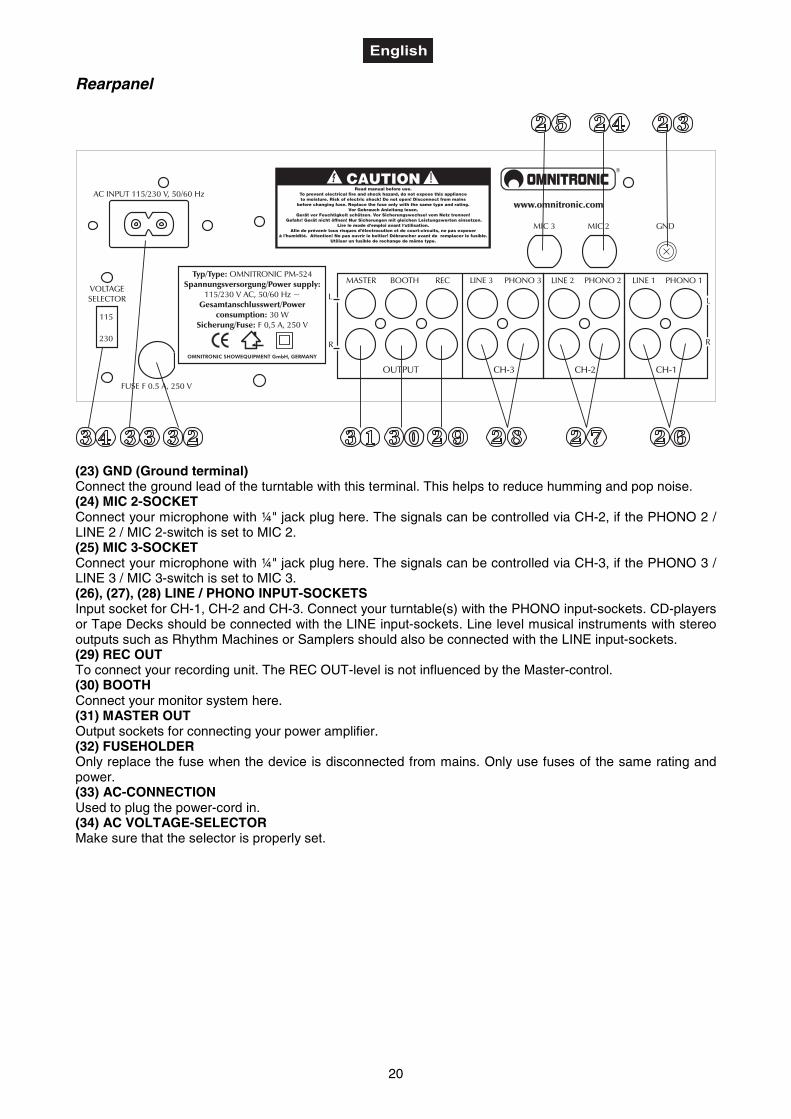
(23) GND (Ground terminal)Connect the ground lead of the turntable with this terminal. This helps to reduce humming and pop noise.(24) MIC 2-SOCKETConnect your microphone with ¼" jack plug here. The signals can be controlled via CH-2, if the PHONO 2 /LINE 2 / MIC 2-switch is set to MIC 2.(25) MIC 3-SOCKETConnect your microphone with ¼" jack plug here. The signals can be controlled via CH-3, if the PHONO 3 /LINE 3 / MIC 3-switch is set to MIC 3.(26), (27), (28) LINE / PHONO INPUT-SOCKETSInput socket for CH-1, CH-2 and CH-3. Connect your turntable(s) with the PHONO input-sockets. CD-playersor Tape Decks should be connected with the LINE input-sockets. Line level musical instruments with stereooutputs such as Rhythm Machines or Samplers should also be connected with the LINE input-sockets.(29) REC OUTTo connect your recording unit. The REC OUT-level is not influenced by the Master-control.(30) BOOTHConnect your monitor system here.(31) MASTER OUTOutput sockets for connecting your power amplifier.(32) FUSEHOLDEROnly replace the fuse when the device is disconnected from mains. Only use fuses of the same rating andpower.(33) AC-CONNECTIONUsed to plug the power-cord in.(34) AC VOLTAGE-SELECTORMake sure that the selector is properly set.
21
PROBLEM CHART
PROBLEM: CAUSE: REMEDY:No power. • The power-cord is not connected. • Check the power-cord and any
extension-cables.No sound. • The PHONO/LINE/MIC-switch of the
respective channel is in the wrongposition.• The power-cord of the respectivedevice is not connected properly ornot connected at all.• The connection-socket or the plug isdirty.
• Put the PHONO/LINE/MIC-switchinto the correct position.• Check the power-cord and if theplugs are tightly connected with thesockets.
• Clean the socket and/or the plug.
Noise. • The input-signal is too strong. • Reduce the input-signal via the Gain-control.
No crossfader. • The crossfader was not assignedproperly.
• Assign the desired channel to thecrossfader via the Crossfader Assign-button.
CLEANING AND MAINTENANCE
Disconnect from mains before starting maintenance operation!
DANGER TO LIFE!
We recommend a frequent cleaning of the device. Please use a soft lint-free and moistened cloth. Never usealcohol or solvents!
There are no servicable parts inside the device except for the fuse. Maintenance and service operations areonly to be carried out by authorized dealers.
Should you need any spare parts, please use genuine parts.
If the power supply cable of this device will be damaged, it has to be replaced by a special power supplycable available at your dealer.
Should you have further questions, please contact your dealer.
Replacing the fuseIf the fine-wire fuse of the device fuses, only replace the fuse by a fuse of same type and rating.
Please note: This fuse is being used for both 115 V and 230 V.
Before replacing the fuse, unplug mains lead.
Procedure:
Step 1: Unscrew the fuseholder on the rearpanel with a fitting screwdriver from the housing (anti-clockwise).
Step 2: Remove the old fuse from the fuseholder.Step 3: Install the new fuse in the fuseholder.Step 4: Replace the fuseholder in the housing and fix it.
22
Replacing the Crossfader
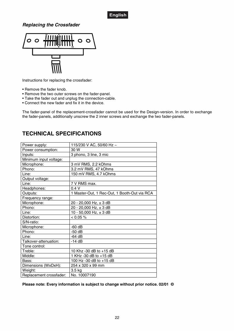
Instructions for replacing the crossfader:
• Remove the fader knob.• Remove the two outer screws on the fader-panel.• Take the fader out and unplug the connection-cable.• Connect the new fader and fix it in the device.
The fader-panel of the replacement-crossfader cannot be used for the Design-version. In order to exchangethe fader-panels, additionally unscrew the 2 inner screws and exchange the two fader-panels.
TECHNICAL SPECIFICATIONS
Power supply: 115/230 V AC, 50/60 Hz ~Power consumption: 30 WInputs: 3 phono, 3 line, 3 micMinimum input voltage:Microphone: 3 mV RMS, 2.2 kOhmsPhono: 3.2 mV RMS, 47 kOhmsLine: 150 mV RMS, 4.7 kOhmsOutput voltage:Line: 7 V RMS max.Headphones: 0.4 VOutputs: 1 Master-Out, 1 Rec-Out, 1 Booth-Out via RCAFrequency range:Microphone: 20 - 20,000 Hz, ± 3 dBPhono: 20 - 20,000 Hz, ± 3 dBLine: 10 - 50,000 Hz, ± 3 dBDistortion: < 0.05 %S/N-ratio:Microphone: -60 dBPhono: -50 dBLine: -64 dBTalkover-attenuation: -14 dBTone control:Treble: 10 Khz -30 dB to +15 dBMiddle: 1 KHz -30 dB to +15 dBBass: 100 Hz -30 dB to +15 dBDimensions (WxDxH): 254 x 320 x 99 mmWeight: 3.5 kgReplacement crossfader: No. 10007190
Please note: Every information is subject to change without prior notice. 02/01 ©


![Udk] sound (sound cue)](https://img.pdfslide.tips/doc/110x75/5562faedd8b42a6f598b4a7e/udk-sound-sound-cue-558499bc022c8.jpg)