Embed Size (px)
Citation preview

This article was downloaded by: [National Chiao Tung University 國立交通大學]On: 28 April 2014, At: 14:21Publisher: Taylor & FrancisInforma Ltd Registered in England and Wales Registered Number: 1072954 Registered office: Mortimer House,37-41 Mortimer Street, London W1T 3JH, UK
Journal of the Chinese Institute of EngineersPublication details, including instructions for authors and subscription information:http://www.tandfonline.com/loi/tcie20
Design of head-mounted-display eyepiece system ofliquid crystal on siliconChien-Yue Chen a , Ming-Da Ke b , Qing-Long Deng c , Yang-Hua Chang a , Ping-Lin Fan d &Shun-Wen Cheng aa Graduate School of Optoelectronics , National Yunlin University of Science andTechnology , Taiwanb Graduate School of Engineering Science and Technology , National Yunlin University ofScience and Technology , Taiwanc Institute of Photonic Systems , National Chiao Tung University , Taiwand Department of Digital Technology Design , National Taipei University of Education , TaiwanPublished online: 21 Mar 2012.
To cite this article: Chien-Yue Chen , Ming-Da Ke , Qing-Long Deng , Yang-Hua Chang , Ping-Lin Fan & Shun-Wen Cheng (2012)Design of head-mounted-display eyepiece system of liquid crystal on silicon, Journal of the Chinese Institute of Engineers,35:3, 343-348, DOI: 10.1080/02533839.2012.655536
To link to this article: http://dx.doi.org/10.1080/02533839.2012.655536
PLEASE SCROLL DOWN FOR ARTICLE
Taylor & Francis makes every effort to ensure the accuracy of all the information (the “Content”) containedin the publications on our platform. However, Taylor & Francis, our agents, and our licensors make norepresentations or warranties whatsoever as to the accuracy, completeness, or suitability for any purpose of theContent. Any opinions and views expressed in this publication are the opinions and views of the authors, andare not the views of or endorsed by Taylor & Francis. The accuracy of the Content should not be relied upon andshould be independently verified with primary sources of information. Taylor and Francis shall not be liable forany losses, actions, claims, proceedings, demands, costs, expenses, damages, and other liabilities whatsoeveror howsoever caused arising directly or indirectly in connection with, in relation to or arising out of the use ofthe Content.
This article may be used for research, teaching, and private study purposes. Any substantial or systematicreproduction, redistribution, reselling, loan, sub-licensing, systematic supply, or distribution in anyform to anyone is expressly forbidden. Terms & Conditions of access and use can be found at http://www.tandfonline.com/page/terms-and-conditions

Journal of the Chinese Institute of EngineersVol. 35, No. 3, April 2012, 343–348
Design of head-mounted-display eyepiece system of liquid crystal on silicon
Chien-Yue Chena*, Ming-Da Keb, Qing-Long Dengc, Yang-Hua Changa,Ping-Lin Fand and Shun-Wen Chenga
aGraduate School of Optoelectronics, National Yunlin University of Science and Technology, Taiwan; bGraduate School ofEngineering Science and Technology, National Yunlin University of Science and Technology, Taiwan; cInstitute of PhotonicSystems, National Chiao Tung University, Taiwan; dDepartment of Digital Technology Design, National Taipei University of
Education, Taiwan
(Received 5 January 2010; final version received 23 November 2010)
The research is aimed at designing an optimized head-mounted-display (HMD) system equipped with two 0.26-inch Liquid Crystal on Silicon display elements for imaging. In order to form an image at a distinct-visiondistance of 250mm, the eyepiece system features 17-times magnification, a 15.63-mm focal length and a 15� fieldof view. Using the resolution of the human eye as the evaluation standard, we analyze the diminution ofaberration and the increase of modulation transfer function, giving the HMD system high resolution as thefinishing touches.
Keywords: LCOS; eyepiece system; head-mounted-display
1. Introduction
In 1960s, Ivan E. Sutherland developed the first head-
mounted-display (HMD) by using a Cathode Ray tube
(CRT), focusing optical system and a computer image
generator to control monitor display signals generated
by head turning (Melzer and Moffitt 1997, Girolamo,
2001). Since 1970, the military of the United States has
applied HMD system to military equipment.Not until Thin Film Transistor-Liquid Crystal
Display (TFT-LCD) began to be used in HMD, did
the weight of HMD equipment decrease much because
HMD had always been mainly composed of a CRT
unit, which had made the systems large and heavy. In
spite of the short 50-year HMD development history,
many display-related technologies have been devel-
oped. Moreover, because the maturity of the technol-
ogies and the low cost of the parts have solved the
problems of low resolution and high price of TFT-
LCD, the prices and sizes of HMD systems have been
going down. Therefore, HMD systems are, now, not
only applied to military affairs but also to entertain-
ment, medicine and education (Mordekhai 1998). In
the process of miniaturizing TFT-LCD display ele-
ments, high resolution cannot be maintained. To
achieve high resolution and small size, Liquid Crystal
on Silicon (LCoS), whose aperture ratio, brightness,
and contrast ratio are better than those of TFT-LCD,
is used for displays. This study has focused on an
LCOS-type HMD design with an optimized eyepiece
system. Because eyepiece systems affect image quality
directly, the aberrations before and after the optimi-
zation are to be analyzed. Additionally, in order to
ensure that the HMD presents a high-quality image,
we evaluate how well the eyepiece matches the resolu-
tion of the human eye.
2. Theories of HMD optical system and
the-resolution-of-the-human-eye analysis
The eyepiece system in an HMD system is used to
enlarge the image from the LCoS, which, then, forms
image on retinas. Thus, the design of the eyepiece
system decides image qualities. Figure 1 shows that the
object y is magnified to y0 . The magnification
calculated by object distance (l) and image distance
(l0) is expressed as in Equation (1). Focal length ( f ),
magnification (M), object distance (l), and image
distance (l0) of eyepiece system are calculated by
Equations (1)–(3). The proper distance between the
eyepiece and the eyes can be set as 5mm (Rosen 1965,
Fedorova and Fedorova 1980, Laikin, 2006). HHMD-
F320B manufactured by Oculon Optoelectronics Inc.
was used as the main system structure in this study as
shown in Figure 2, and the side view of the optical
system is depicted as shown in Figure 3. To improve
*Corresponding author. Email: [email protected]
ISSN 0253–3839 print/ISSN 2158–7299 online
� 2012 The Chinese Institute of Engineers
http://dx.doi.org/10.1080/02533839.2012.655536
http://www.tandfonline.com
Dow
nloa
ded
by [
Nat
iona
l Chi
ao T
ung
Uni
vers
ity ]
at 1
4:21
28
Apr
il 20
14

the eyepiece system, we will simulate and optimize it
for increasing its resolution.
M ¼l0
lð1Þ
l ¼1
M� 1
� �f ð2Þ
l0 ¼ 1�Mð Þ f ð3Þ
To decide whether the image quality meets the
needs of the human eye, this optical system was
evaluated by standards matching the resolution of the
human eye. On the standard of spatial frequency
resolution of modulation transfer function (MTF), the
number of recognizable black and white lines within1mm decides the largest effective spatial frequency(Lin et al. 1989, Smith 1990). From Weymouth (1958),we know that the minimum resolution of the humaneye on the optic axis is 1 minute of angle (MOA), andthe half-view angle of the HMD we have designed is12�, which equates to four MOA. As shown inFigure 4, after being refracted, the d between the twopoints form an angle � and a 1-MOA image onthe retina. Equation (4) is used to calculate theminimum value d, which is 250mm away fromthe eyeball. After the calculation, we know that theminimum d, when it forms a 1-MOA image onthe retina, is 0.0727mm. That is to say that when theformed image on the retina becomes 4 MOA, dincreases to 0.2909mm. Then, we substitutespatial frequency into Equation (5), obtaining 6.88 lp/mm and 1.72lp/mm at 1 MOA and 4 MOA, respec-tively (Toet and Levi 1992, Lyons and Mouroulis1996). Consequently, the highest recognizable spatialfrequency of the human eye at 1 MOA is 6.88 lp/mm.
d ¼1
60�
�
180� 250 ð4Þ
Spatial frequency
¼1
2�minimumwidth recognizable by the human eye
�ðlp=mmÞ ð5Þ
3. Simulation and optimization of the optical system
This study is aimed at designing a 0.26-inch LCoSHMDeyepiece that canmake the LCoS image form at 250mmaway from viewer’s eyes, so that a magnified virtualimage can be obtained. The specifications of an eyepieceusing United States Patent US 2002/0180662 (Ko et al.2002) are exhibited in Table 1, and the lens data ofPatent U6,349,004 (Robert et al. 2002) in Table 2.
Figure 2. HMD-F320B system structure.
Figure 3. Side view of HMD optical system.
Figure 4. Illustration of human eyes resolution.Figure 1. Object image magnified by eyepiece system.
344 C.-Y. Chen et al.
Dow
nloa
ded
by [
Nat
iona
l Chi
ao T
ung
Uni
vers
ity ]
at 1
4:21
28
Apr
il 20
14
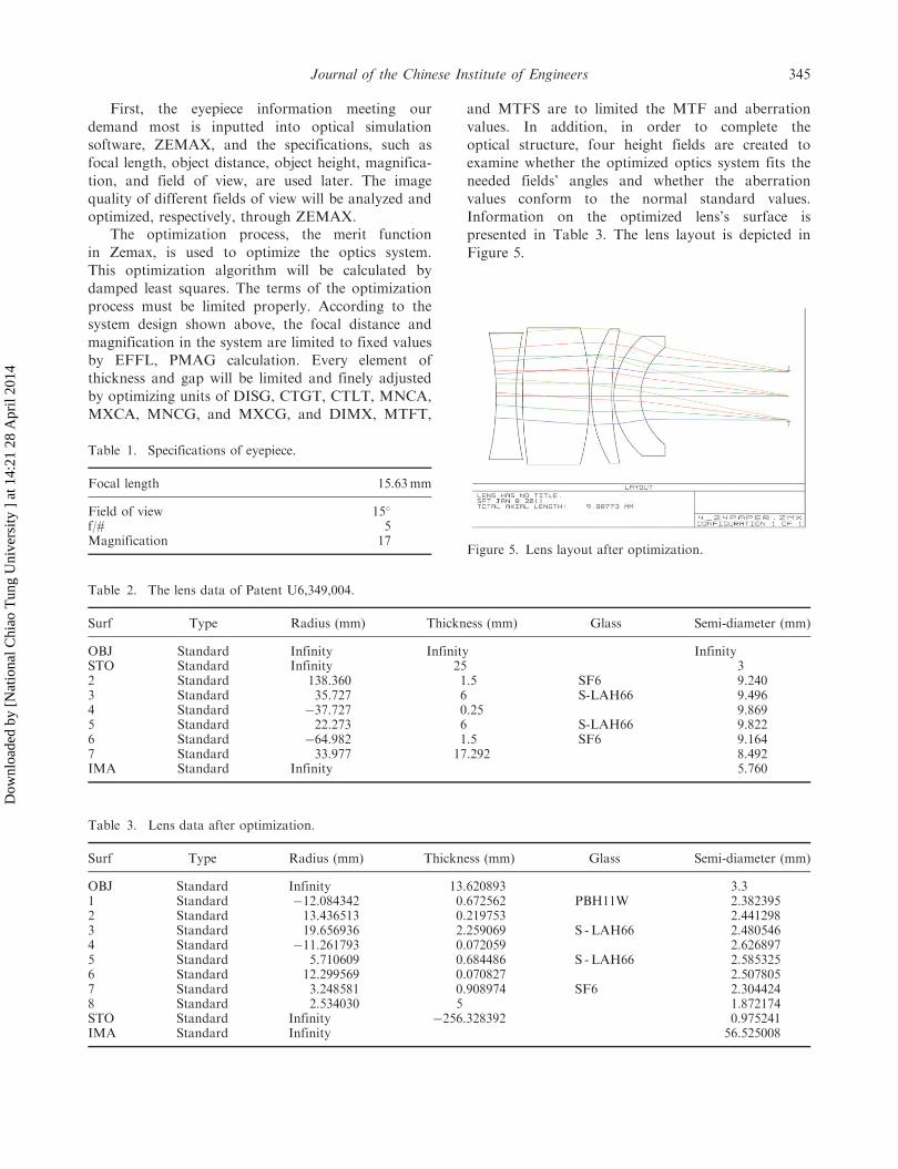
First, the eyepiece information meeting our
demand most is inputted into optical simulation
software, ZEMAX, and the specifications, such as
focal length, object distance, object height, magnifica-
tion, and field of view, are used later. The image
quality of different fields of view will be analyzed and
optimized, respectively, through ZEMAX.The optimization process, the merit function
in Zemax, is used to optimize the optics system.
This optimization algorithm will be calculated by
damped least squares. The terms of the optimization
process must be limited properly. According to the
system design shown above, the focal distance and
magnification in the system are limited to fixed values
by EFFL, PMAG calculation. Every element of
thickness and gap will be limited and finely adjusted
by optimizing units of DISG, CTGT, CTLT, MNCA,
MXCA, MNCG, and MXCG, and DIMX, MTFT,
and MTFS are to limited the MTF and aberration
values. In addition, in order to complete the
optical structure, four height fields are created to
examine whether the optimized optics system fits the
needed fields’ angles and whether the aberration
values conform to the normal standard values.
Information on the optimized lens’s surface is
presented in Table 3. The lens layout is depicted in
Figure 5.
Table 3. Lens data after optimization.
Surf Type Radius (mm) Thickness (mm) Glass Semi-diameter (mm)
OBJ Standard Infinity 13.620893 3.31 Standard �12.084342 0.672562 PBH11W 2.3823952 Standard 13.436513 0.219753 2.4412983 Standard 19.656936 2.259069 S - LAH66 2.4805464 Standard �11.261793 0.072059 2.6268975 Standard 5.710609 0.684486 S - LAH66 2.5853256 Standard 12.299569 0.070827 2.5078057 Standard 3.248581 0.908974 SF6 2.3044248 Standard 2.534030 5 1.872174STO Standard Infinity �256.328392 0.975241IMA Standard Infinity 56.525008
Table 2. The lens data of Patent U6,349,004.
Surf Type Radius (mm) Thickness (mm) Glass Semi-diameter (mm)
OBJ Standard Infinity Infinity InfinitySTO Standard Infinity 25 32 Standard 138.360 1.5 SF6 9.2403 Standard 35.727 6 S-LAH66 9.4964 Standard �37.727 0.25 9.8695 Standard 22.273 6 S-LAH66 9.8226 Standard �64.982 1.5 SF6 9.1647 Standard 33.977 17.292 8.492IMA Standard Infinity 5.760
Figure 5. Lens layout after optimization.
Table 1. Specifications of eyepiece.
Focal length 15.63mm
Field of view 15�
f/# 5Magnification 17
Journal of the Chinese Institute of Engineers 345
Dow
nloa
ded
by [
Nat
iona
l Chi
ao T
ung
Uni
vers
ity ]
at 1
4:21
28
Apr
il 20
14

This study set manufacturing errors including the
lens thickness and the air gap distance. The MTF
performance was used as the merit function in the
tolerance process. Figure 6 shows the manufacturing
errors of the MTF at 6.88 lp/mm based on the
manufacturing error. The plot suggests that the MTF
degradation at a given �0.02 manufacturing error is
�3.12%, �4.49%, �2.91%, and �2.0% at the four
real image heights from 0 to 56.3mm, which is
acceptable for our system.
4. Result and discussion
Figure 7 shows the structure of the lens system after
optimization. ‘1’ is image position, ‘2’ exhibits LCoS
image element position, ‘3’ depicts eyepiece system,
and ‘4’ shows the position of viewer’s eye. The
magnification principle can be interpreted clearly
from the layout.
Figure 8. (a) Field curvature and distortion and (b) transverse chromatic aberration before and after optimization.
Figure 7. System layout after the optimization.Figure 6. The manufacturing errors for the MTF tolerance.
346 C.-Y. Chen et al.
Dow
nloa
ded
by [
Nat
iona
l Chi
ao T
ung
Uni
vers
ity ]
at 1
4:21
28
Apr
il 20
14

Field curvature, distortion, and transverse
chromatic aberration before and after optimization
are depicted in Figure 8 and sorted in Table 4.
The transverse chromatic aberration and the field
curvature decrease from �158.28 mm and 39.73mm to
�18.19mm and 15.73mm, respectively. The distortion
is reduced from 34% to 0.96%. As the result shows,
system aberrations can be greatly lessened via the
optimization.Figure 9 shows the relation between the MTF and
the field. The MTF differences between the tangential
surface and the agittal surface of the eyepiece system
are small. If the MTF differences were greater than
10%, the aberrations would lead to aberration prob-
lem. Our system design has no such problems.The simulation result shown in Figure 10 tells
whether the MTF matches the needs of the human eye.
We have obtained the highest spatial frequency 6.88 lp/
mm from previous calculations. Human eyes cannot
discern an image when its spatial frequency is higher
than 6.88 lp/mm. MTF values before and after opti-
mization are sorted in Table 5. The greater the MTF
value, the higher the image resolution. Before the
optimization, the MTF value at 1 MOA was only 0.09,
and after the optimization, the MTF value has
increased to above 0.3. Photoreceptor cells within the
range of 1 MOA on the retina are the most sensitive,and after the optimization, the resolution at 1 MOAappears higher, which greatly improves the quality ofthe eyepiece system. Moreover, the MTF values at 2, 3,and 4 MOA reach above 0.66, making human eyes seeimages more distinctly.
Good image quality can be acquired throughsimulation. Long focal lengths between 20 and 30mmare normally used in HMD optical systems (Zhao et al.2007, Zhang and Hua 2008). However, in order toshorten the length of the system, the focal length15.625mm is adopted in the research. For the sake oflight weight and miniaturization, plastics are used asthe material of the eyepiece system.
5. Conclusions
HMD systems have been commonly applied in theoptical industry recently. Their handiness and
Figure 10. MTF values before and after optimization.Figure 9. MTF vs. field after optimization.
Table 4. Aberrations comparison before and afteroptimization.
Transversechromatic
aberration (mm)
Fieldcurvature(mm)
Distortion(%)
Before �158.28 �39.73 2.34After �18.19 �15.73 0.96
Journal of the Chinese Institute of Engineers 347
Dow
nloa
ded
by [
Nat
iona
l Chi
ao T
ung
Uni
vers
ity ]
at 1
4:21
28
Apr
il 20
14

resolution are worth improving. This study is aimed atoptimizing the eyepiece system and finding the humaneye’s greatest tolerance toward the system. As thisstudy shows, the MTF at 1 MOA increases from 0.09to 0.36 after optimization. Additionally, to achievehigh resolution, field curvature, distortions, and trans-verse chromatic aberrations have been reduced. Shortfocal length shortens the length of the whole system,and plastics reduce the weight of the HMD. Therefore,using diffraction elements on the surface of the lens tothin lens thickness and to achieve better resolution willbe an important issue in the near future (Zhao et al.2004).
References
Fedorova, N.S. and Fedorova, G.A., 1980. Relationship
between MTF and visual resolution of a telescope. Soviet
journal of optical technology, 47, 1–4.Girolamo, H., 2001. A decade of progress 1991–2001: HMD
technology ready for platform iintegration. Proceedings of
SPIE, Vol. 4361, pp. 43-70.Laikin, M., 2006. Lens design. 4th ed. Wayne, NJ, USA:
CRC Press.Lin, S.H., et al., 1989. Stability of perturbed polynomials
based on the principle of the argument and
Nyquist criterion. International journal of contral, 50 (1),
55–63.
Lyons, K. and Mouroulis, P., 1996. Effect of instrumental
spherical aberration on visual image quality. Journal of the
optical society of America A – optics image science and
vision, 13 (2), 193–204.Melzer, J.E. and Moffitt, K., 1997. Head-mounted displays
designing for the user. New York, USA: McGraw Hill, 125.Mordekhai, V., 1998. Helmet-mounted displays and sights.
London, UK: Artech House.Robert, E. F. and Micheal, P.N., 2002.Head mounted display
viewing optics with improved optical performance. United
States Patent Application No. 6349004.Rosen, S, 1965. Eyepiece and magnifiers. In: R. Kingslake,
ed. Applied optics and optical engineering. Vol. 3,
New York, USA: Academic Press, Chapter 9.Smith, W.J., 1990. Modern optical engineering: the design of
optical systems. New York, USA: Mcgraw-Hill.Toet, A. and Levi, D.M., 1992. The two-dimensional shape
of spatial interaction zones in the parafovea. Vision
research, 32 (7), 1349–1357.Weymouth, F.W., 1958. Visual sensory units and the
minimal angle of resolution. American journal of ophthal-
mology, 46 (1), 102–113.Zhang, R. and Hua, H., 2008. Design of a polarized
head-mounted projection display using ferroelectric
liquid-crystal-on-silicon microdisplays. Applied optics, 47
(15), 2888–2896.Zhao, Q.L., et al., 2004. Head-mounted display with LCOS
using diffractive optical element. Optik, 115 (1), 11–14.Zhao, Q.L., Wang, Z.Q., and Liu, T.G., 2007. Design of
optical system for head-mounted micro-display. Optik, 118
(1), 29–33.
Table 5. Corresponding values of human eyes resolution and the MTF.
Human eyesresolution Field
Spatial frequency(lp/mm)
MTF value beforeoptimization
MTF value afteroptimization
Diffractionlimit
One minute angle 0� 6.88 0.09 0.36 0.38Two minute angles 5� 3.44 0.44 0.66 0.66Three minute angles 8� 2.29 0.53 0.75 0.77Four minute angles 12� 1.72 0.56 0.74 0.83
348 C.-Y. Chen et al.
Dow
nloa
ded
by [
Nat
iona
l Chi
ao T
ung
Uni
vers
ity ]
at 1
4:21
28
Apr
il 20
14


![INDEX []PTFE FEP ETFE PFA A B AT03A010 AF06A010 AE09A010 AA18A010 1/0.20 0.20 0.031 0.4 1.00 582 614 3000 1500 AT03A020 AF06A020 AE09A020 AA18A020 1/0.26 0.26 0.053 0.4 1.06 345 359](https://img.pdfslide.tips/doc/110x75/60c0173830a83c414c44797a/index-ptfe-fep-etfe-pfa-a-b-at03a010-af06a010-ae09a010-aa18a010-1020-020.jpg)