Embed Size (px)
Citation preview

Integrated Amplifier
Operating Instructions
A10_DLPWXE.book 1 ページ 2012年3月13日 火曜日 午後4時33分
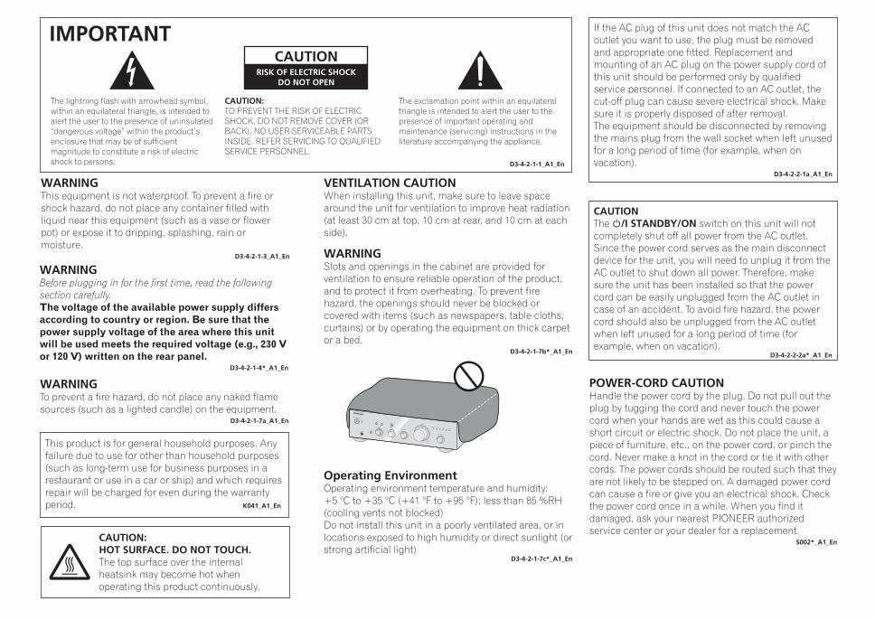
The exclamation point within an equilateral triangle is intended to alert the user to the presence of important operating and maintenance (servicing) instructions in the literature accompanying the appliance.
The lightning flash with arrowhead symbol, within an equilateral triangle, is intended to alert the user to the presence of uninsulated “dangerous voltage” within the product’s enclosure that may be of sufficient magnitude to constitute a risk of electric shock to persons.
CAUTION:TO PREVENT THE RISK OF ELECTRIC SHOCK, DO NOT REMOVE COVER (OR BACK). NO USER-SERVICEABLE PARTS INSIDE. REFER SERVICING TO QUALIFIED SERVICE PERSONNEL.
CAUTIONRISK OF ELECTRIC SHOCK
DO NOT OPEN
IMPORTANT
D3-4-2-1-1_A1_En
WARNINGThis equipment is not waterproof. To prevent a fire or shock hazard, do not place any container filled with liquid near this equipment (such as a vase or flower pot) or expose it to dripping, splashing, rain or moisture.
D3-4-2-1-3_A1_En
WARNINGBefore plugging in for the first time, read the following section carefully.The voltage of the available power supply differs according to country or region. Be sure that the power supply voltage of the area where this unit will be used meets the required voltage (e.g., 230 V or 120 V) written on the rear panel.
D3-4-2-1-4*_A1_En
WARNINGTo prevent a fire hazard, do not place any naked flame sources (such as a lighted candle) on the equipment.
D3-4-2-1-7a_A1_En
VENTILATION CAUTIONWhen installing this unit, make sure to leave space around the unit for ventilation to improve heat radiation (at least 30 cm at top, 10 cm at rear, and 10 cm at each side).
WARNINGSlots and openings in the cabinet are provided for ventilation to ensure reliable operation of the product, and to protect it from overheating. To prevent fire hazard, the openings should never be blocked or covered with items (such as newspapers, table-cloths, curtains) or by operating the equipment on thick carpet or a bed.
D3-4-2-1-7b*_A1_En
Operating EnvironmentOperating environment temperature and humidity:+5 °C to +35 °C (+41 °F to +95 °F); less than 85 %RH (cooling vents not blocked)Do not install this unit in a poorly ventilated area, or in locations exposed to high humidity or direct sunlight (or strong artificial light)
D3-4-2-1-7c*_A1_En
This product is for general household purposes. Any failure due to use for other than household purposes (such as long-term use for business purposes in a restaurant or use in a car or ship) and which requires repair will be charged for even during the warranty period. K041_A1_En
POWER-CORD CAUTIONHandle the power cord by the plug. Do not pull out the plug by tugging the cord and never touch the power cord when your hands are wet as this could cause a short circuit or electric shock. Do not place the unit, a piece of furniture, etc., on the power cord, or pinch the cord. Never make a knot in the cord or tie it with other cords. The power cords should be routed such that they are not likely to be stepped on. A damaged power cord can cause a fire or give you an electrical shock. Check the power cord once in a while. When you find it damaged, ask your nearest PIONEER authorized service center or your dealer for a replacement.
S002*_A1_En
If the AC plug of this unit does not match the AC outlet you want to use, the plug must be removed and appropriate one fitted. Replacement and mounting of an AC plug on the power supply cord of this unit should be performed only by qualified service personnel. If connected to an AC outlet, the cut-off plug can cause severe electrical shock. Make sure it is properly disposed of after removal.The equipment should be disconnected by removing the mains plug from the wall socket when left unused for a long period of time (for example, when on vacation).
D3-4-2-2-1a_A1_En
CAUTIONThe /I STANDBY/ON switch on this unit will not completely shut off all power from the AC outlet. Since the power cord serves as the main disconnect device for the unit, you will need to unplug it from the AC outlet to shut down all power. Therefore, make sure the unit has been installed so that the power cord can be easily unplugged from the AC outlet in case of an accident. To avoid fire hazard, the power cord should also be unplugged from the AC outlet when left unused for a long period of time (for example, when on vacation).
D3-4-2-2-2a*_A1_En
CAUTION:HOT SURFACE. DO NOT TOUCH.The top surface over the internal heatsink may become hot when operating this product continuously.
A10_DLPWXE.book 2 ページ 2012年3月13日 火曜日 午後4時33分

3
Thank you for buying this Pioneer product.Please read through these operating instructions so that you will know how to operate your model properly. After you have finished reading the instructions, put them in a safe place for future reference.
Contents01 Before you startWhat’s in the box . . . . . . . . . . . . . . . . . . . . . . . . . 4Installing the amplifier . . . . . . . . . . . . . . . . . . . . . 4
02 Connecting upMaking cable connections . . . . . . . . . . . . . . . . . . 5About “Bi-wiring” . . . . . . . . . . . . . . . . . . . . . . . . . 5Connecting speaker cables . . . . . . . . . . . . . . . . . 6Connecting audio cables . . . . . . . . . . . . . . . . . . . 6Plugging in. . . . . . . . . . . . . . . . . . . . . . . . . . . . . . 6
03 Controls and displaysFront panel . . . . . . . . . . . . . . . . . . . . . . . . . . . . . . 7Rear panel . . . . . . . . . . . . . . . . . . . . . . . . . . . . . . 8
04 OperationPlayback. . . . . . . . . . . . . . . . . . . . . . . . . . . . . . . . 9Making an audio recording. . . . . . . . . . . . . . . . . . 9To set for automatic standby status (Auto Power Down) . . . . . . . . . . . . . . . . . . . . . . 10Restoring all the settings to the factory default settings . . . . . . . . . . . . . . . . . . . . . . . . . . . . . . . 10
05 Additional informationTroubleshooting . . . . . . . . . . . . . . . . . . . . . . . . . 11Cleaning the unit . . . . . . . . . . . . . . . . . . . . . . . . 11Specifications. . . . . . . . . . . . . . . . . . . . . . . . . . . 11
A10_DLPWXE.book 3 ページ 2012年3月13日 火曜日 午後4時33分

01 Before you start
4En
Chapter 1:
Before you start
What’s in the boxPlease confirm that the following accessories are in the box when you open it.
• Power cord• Operating instructions (This document)
Note
• Illustrations featured in the Operating Instructions may have been modified or simplified for ease of explanation, and may therefore differ from the actual product appearance.
Installing the amplifierWhen installing this unit, make sure to put it on a level and stable surface.
• Don’t install it on the following places:– on a color TV (the screen may distort)– near a cassette deck (or close to a device that gives off a magnetic field). This may interfere with the sound.– in direct sunlight– in damp or wet areas– in extremely hot or cold areas– in places where there is vibration or other movement– in places that are very dusty– in places that have hot fumes or oils (such as a kitchen)
• Do not mount the unit on a sofa or other object or material with absorbent qualities, since sound quality may be adversely affected.
A10_DLPWXE.book 4 ページ 2012年3月13日 火曜日 午後4時33分

Connecting up 02
5En
EnglishD
eutschFrançais
NederlandsItaliano
EspañolРусский
Chapter 2:
Connecting up
Making cable connections
Caution
• Before making or changing the connections, switch off the power and disconnect the power cord from the AC outlet.
• Connect the power cord after all the connections between devices have been completed.
REC
R
LOUTPUT
R
L
PLAYR LAUDIOOUTPUT
LR LR LR
L
R
LRLR
L
R
L
R
L
R
L R L R
LR LR
MENU
iPod
Music>Extras>Settings>Shuffle SongsBacklight
SACD/CD playerNetwork audio player
Speaker system B
Speaker system ATurntable Tuner iPod dock, etc CD recorder or
tape deckRight Left
Right Left
This unit’s rear panel
Power cord (included)
Caution
• The SIGNAL GND terminal is provided to reduce noise when connecting the unit to components such as an analog turntable.
• Do not connect the PHONO (MM) terminals to any component other than a turntable; also, do not connect to a turntable equipped with built-in equalizer. An excessively high sound output may be produced, resulting in damage to your speakers or other devices.
• The unit’s PHONO (MM) terminals are designed to be used with turntables equipped with MM (moving-magnet) type cartridges. Turntables equipped with MC (moving-coil) cartridges cannot be used.
• Make sure not to bend the cables over the top of this unit (as shown in the illustration). If this happens, the magnetic field produced by the transformers in this unit may cause a humming noise from the speakers.
• If your turntable has a grounding wire, secure it to the ground terminal on this amplifier.
Note
• When connecting a tape cassette deck, playback noise may be heard, depending on the installation location. This noise is caused by leakage flux from the amplifier’s transformer. In this event, change the installation location, or move the deck farther from the amplifier.
• iPod is a trademark of Apple Inc., registered in the U.S. and other countries.
About “Bi-wiring”This unit can be used with speakers that support bi-wiring. Be sure to connect the high-frequency andlow-frequency connections correctly.
• During playback, be sure that both the SPEAKERS A button and SPEAKERS B button are set to ON (page 7).
Caution
• When using bi-wiring to connect speakers, avoid adverse affects on the amplifier by being sure to remove the HIGH and LOW short bars provided with the speakers. For detailed information, consult the instructions provided with the speakers.
• When using speakers with removable network circuits, note that if the network is removed, no effect will be produced and damage may be caused to the speaker.
• Another method of connection is to connect the SPEAKERS A terminals to HIGH and the SPEAKERS B terminals to LOW (reverse that shown in the illustration).
HIGH
LOW
HIGH
LOW
Speaker systemLeft
Speaker systemRight
This unit’s rear panel
Remove the shorting bar between the +
and – terminals.
A10_DLPWXE.book 5 ページ 2012年3月13日 火曜日 午後4時33分
02 Connecting up
6En
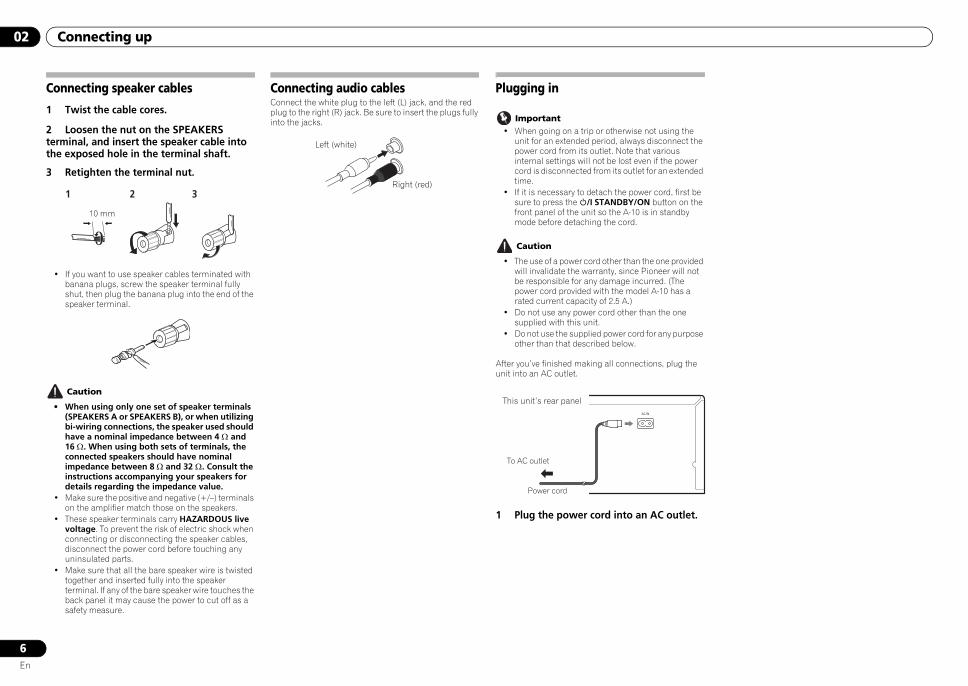
Connecting speaker cables
1 Twist the cable cores.
2 Loosen the nut on the SPEAKERS terminal, and insert the speaker cable into the exposed hole in the terminal shaft.
3 Retighten the terminal nut.
• If you want to use speaker cables terminated with banana plugs, screw the speaker terminal fully shut, then plug the banana plug into the end of the speaker terminal.
Caution
• When using only one set of speaker terminals (SPEAKERS A or SPEAKERS B), or when utilizing bi-wiring connections, the speaker used should have a nominal impedance between 4 Ω and 16 Ω. When using both sets of terminals, the connected speakers should have nominal impedance between 8 Ω and 32 Ω. Consult the instructions accompanying your speakers for details regarding the impedance value.
• Make sure the positive and negative (+/–) terminals on the amplifier match those on the speakers.
• These speaker terminals carry HAZARDOUS live voltage. To prevent the risk of electric shock when connecting or disconnecting the speaker cables, disconnect the power cord before touching any uninsulated parts.
• Make sure that all the bare speaker wire is twisted together and inserted fully into the speaker terminal. If any of the bare speaker wire touches the back panel it may cause the power to cut off as a safety measure.
Connecting audio cablesConnect the white plug to the left (L) jack, and the red plug to the right (R) jack. Be sure to insert the plugs fully into the jacks.
1 2 3
10 mm
Left (white)
Right (red)
Plugging in
Important• When going on a trip or otherwise not using the
unit for an extended period, always disconnect the power cord from its outlet. Note that various internal settings will not be lost even if the power cord is disconnected from its outlet for an extended time.
• If it is necessary to detach the power cord, first be sure to press the /I STANDBY/ON button on the front panel of the unit so the A-10 is in standby mode before detaching the cord.
Caution
• The use of a power cord other than the one provided will invalidate the warranty, since Pioneer will not be responsible for any damage incurred. (The power cord provided with the model A-10 has a rated current capacity of 2.5 A.)
• Do not use any power cord other than the one supplied with this unit.
• Do not use the supplied power cord for any purpose other than that described below.
After you’ve finished making all connections, plug the unit into an AC outlet.
1 Plug the power cord into an AC outlet.
To AC outlet
Power cord
This unit’s rear panel
A10_DLPWXE.book 6 ページ 2012年3月13日 火曜日 午後4時33分
Controls and displays 03
7En
EnglishD
eutschFrançais
NederlandsItaliano
EspañolРусский
Chapter 3:
Controls and displays
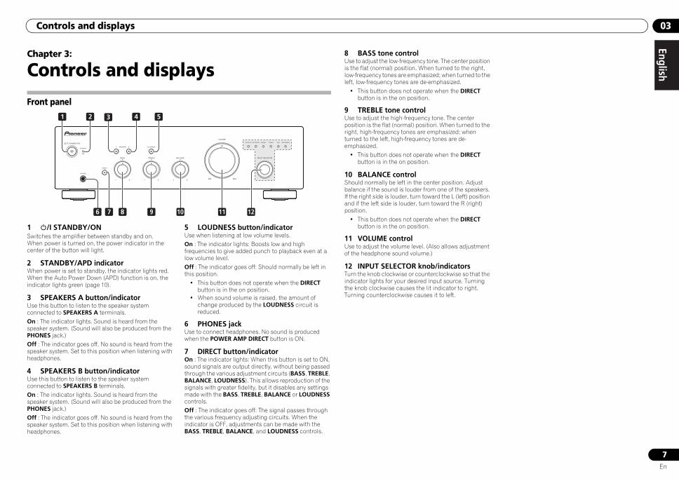
Front panel
1 /I STANDBY/ONSwitches the amplifier between standby and on.When power is turned on, the power indicator in the center of the button will light.
2 STANDBY/APD indicatorWhen power is set to standby, the indicator lights red. When the Auto Power Down (APD) function is on, the indicator lights green (page 10).
3 SPEAKERS A button/indicatorUse this button to listen to the speaker system connected to SPEAKERS A terminals.On : The indicator lights. Sound is heard from the speaker system. (Sound will also be produced from the PHONES jack.)Off : The indicator goes off. No sound is heard from the speaker system. Set to this position when listening with headphones.
4 SPEAKERS B button/indicatorUse this button to listen to the speaker system connected to SPEAKERS B terminals.On : The indicator lights. Sound is heard from the speaker system. (Sound will also be produced from the PHONES jack.)Off : The indicator goes off. No sound is heard from the speaker system. Set to this position when listening with headphones.
5 LOUDNESS button/indicatorUse when listening at low volume levels.On : The indicator lights: Boosts low and high frequencies to give added punch to playback even at a low volume level.Off : The indicator goes off: Should normally be left in this position.
• This button does not operate when the DIRECT button is in the on position.
• When sound volume is raised, the amount of change produced by the LOUDNESS circuit is reduced.
6 PHONES jackUse to connect headphones. No sound is produced when the POWER AMP DIRECT button is ON.
7 DIRECT button/indicatorOn : The indicator lights: When this button is set to ON, sound signals are output directly, without being passed through the various adjustment circuits (BASS, TREBLE, BALANCE, LOUDNESS). This allows reproduction of the signals with greater fidelity, but it disables any settings made with the BASS, TREBLE, BALANCE or LOUDNESS controls.Off : The indicator goes off: The signal passes through the various frequency adjusting circuits. When the indicator is OFF, adjustments can be made with the BASS, TREBLE, BALANCE, and LOUDNESS controls.
31 2 54
6 128 9 10 117
8 BASS tone controlUse to adjust the low-frequency tone. The center position is the flat (normal) position. When turned to the right, low-frequency tones are emphasized; when turned to the left, low-frequency tones are de-emphasized.
• This button does not operate when the DIRECT button is in the on position.
9 TREBLE tone controlUse to adjust the high-frequency tone. The center position is the flat (normal) position. When turned to the right, high-frequency tones are emphasized; when turned to the left, high-frequency tones are de-emphasized.
• This button does not operate when the DIRECT button is in the on position.
10 BALANCE controlShould normally be left in the center position. Adjust balance if the sound is louder from one of the speakers. If the right side is louder, turn toward the L (left) position and if the left side is louder, turn toward the R (right) position.
• This button does not operate when the DIRECT button is in the on position.
11 VOLUME controlUse to adjust the volume level. (Also allows adjustment of the headphone sound volume.)
12 INPUT SELECTOR knob/indicatorsTurn the knob clockwise or counterclockwise so that the indicator lights for your desired input source. Turning the knob clockwise causes the lit indicator to right. Turning counterclockwise causes it to left.
A10_DLPWXE.book 7 ページ 2012年3月13日 火曜日 午後4時33分

03 Controls and displays
8En
Rear panel
See pages 5 to 6 for details regarding connections.
1 GND (Turntable ground) terminalThis ground terminal is designed to help reduce noise when a turntable is connected. It is not a safety ground.
2 SPEAKERS A terminals (Right channel)
3 SPEAKERS B terminals (Right channel)
4 SPEAKERS B terminals (Left channel)
5 SPEAKERS A terminals (Left channel)
6 AC IN jackConnect power cord to here and an AC wall socket.
7 PHONO (MM) IN terminals
8 TUNER IN terminals
9 SACD/CD IN terminals
10 AUX IN terminals
11 NETWORK IN terminals
12 RECORDER IN/OUT terminals
1
7
28 210
9 11
212
22 23 24 25 6
A10_DLPWXE.book 8 ページ 2012年3月13日 火曜日 午後4時33分
Operation 04
9En
EnglishD
eutschFrançais
NederlandsItaliano
EspañolРусский
Chapter 4:
Operation
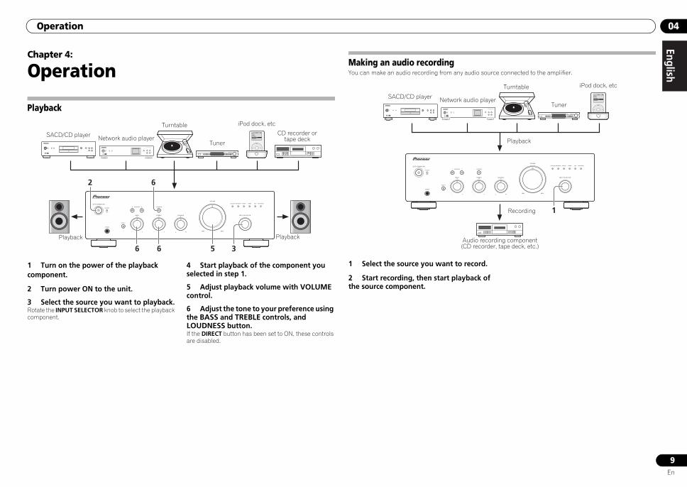
Playback
1 Turn on the power of the playback component.
2 Turn power ON to the unit.
3 Select the source you want to playback.Rotate the INPUT SELECTOR knob to select the playback component.
4 Start playback of the component you selected in step 1.
5 Adjust playback volume with VOLUME control.
6 Adjust the tone to your preference using the BASS and TREBLE controls, and LOUDNESS button.If the DIRECT button has been set to ON, these controls are disabled.
62
3566
MENU
iPod
Music>Extras>Settings>Shuffle SongsBacklight
/I STANDBY/ON
STANDBY
iPod/USB5V 2.1A
PURE AUDIO Hi-Bit 32
FUNCTION
NETWORK AUDIO PLAYER N-50
SACD/CD player Network audio player
Turntable
Tuner
iPod dock, etc
CD recorder or tape deck
Playback Playback
Making an audio recordingYou can make an audio recording from any audio source connected to the amplifier.
1 Select the source you want to record.
2 Start recording, then start playback of the source component.
1
MENU
iPod
Music>Extras>Settings>Shuffle SongsBacklight
/I STANDBY/ON
STANDBY
iPod/USB5V 2.1A
PURE AUDIO Hi-Bit 32
FUNCTION
NETWORK AUDIO PLAYER N-50
SACD/CD player Network audio player
Turntable
Tuner
iPod dock, etc
Audio recording component (CD recorder, tape deck, etc.)
Playback
Recording
A10_DLPWXE.book 9 ページ 2012年3月13日 火曜日 午後4時33分
04 Operation
10En
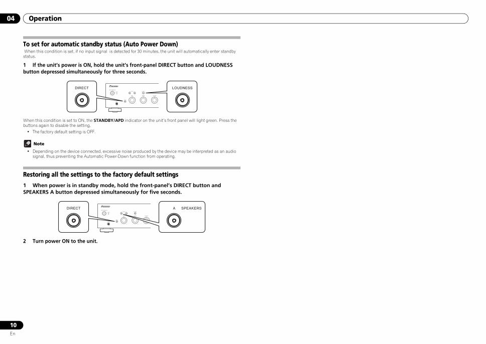
To set for automatic standby status (Auto Power Down) When this condition is set, if no input signal is detected for 30 minutes, the unit will automatically enter standby status.
1 If the unit’s power is ON, hold the unit’s front-panel DIRECT button and LOUDNESS button depressed simultaneously for three seconds.
When this condition is set to ON, the STANDBY/APD indicator on the unit’s front panel will light green. Press the buttons again to disable the setting.
• The factory default setting is OFF.
Note
• Depending on the device connected, excessive noise produced by the device may be interpreted as an audio signal, thus preventing the Automatic Power-Down function from operating.
Restoring all the settings to the factory default settings
1 When power is in standby mode, hold the front-panel’s DIRECT button and SPEAKERS A button depressed simultaneously for five seconds.
2 Turn power ON to the unit.
A10_DLPWXE.book 10 ページ 2012年3月13日 火曜日 午後4時33分
Additional information 05
11En
EnglishD
eutschFrançais
NederlandsItaliano
EspañolРусский
Chapter 5:
Additional information
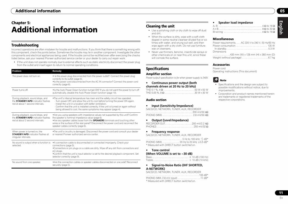
TroubleshootingIncorrect operations are often mistaken for trouble and malfunctions. If you think that there is something wrong with this component, check the points below. Sometimes the trouble may lie in another component. Investigate the other components and electrical appliances being used. If the trouble cannot be rectified even after exercising the checks listed below, ask your nearest Pioneer authorized service center or your dealer to carry out repair work.
• If the unit does not operate normally due to external effects such as static electricity disconnect the power plug from the outlet and insert again to return to normal operating conditions.
Problem Remedy
The power does not turn on. • Is the power plug disconnected from the power outlet? Connect the power plug correctly to its outlet (page 6).•Is the power cord disconnected from the AC IN connector? Connect the power cord correctly (page 6).
Power turns off. •Is the Auto Power Down function turned ON? If you do not want the power to turn off automatically, disable the Auto Power Down function (page 10).
During playback, sound stops, and the STANDBY/APD indicator flashes red at about 1 second intervals.
•The unit’s internal temperature has risen and the safety circuit has operated. - Turn power OFF, and allow the unit to cool before turning the power ON again.- Install the unit in a location with better ventilation.- Confirm that the unit is installed correctly; if the unit is turned on again without being allowed to cool, the same symptoms may appear (page 4).
During playback, sound stops, and the STANDBY/APD indicator flashes red at about 2 second intervals.
•Are you using speakers with impedance values not supported by this unit? Confirm the speaker’s nominal impedance value (page 6).•Are any speaker cables loose from the SPEAKERS terminals and touching other wires or the surface of the rear panel? Disconnect the power cord and reconnect the speaker cables correctly (page 6).
When power is turned on, the STANDBY/APD indicator flashes at irregular intervals.
•The unit’s circuitry is damaged. Disconnect the power cord and consult your dealer or nearest Pioneer authorized service center.
No sound is output when a function is selected.
•A connection cable is disconnected or connected improperly. Check your connections (page 5).•Connectors or pin plugs on a cable are dirty. Wipe off any dirt from connectors and pin plugs.•Confirm that the unit’s input selector is set to the desired playback component. Set selector correctly (page 9).
No sound from one speaker. •Are the connection cables or speaker cables disconnected on one side? Reconnect securely (page 5).
Cleaning the unit• Use a polishing cloth or dry cloth to wipe off dust
and dirt.• When the surface is dirty, wipe with a soft cloth
dipped in some neutral cleanser diluted five or six times with water, and wrung out well, and then wipe again with a dry cloth. Do not use furniture wax or cleansers.
• Never use thinners, benzine, insecticide sprays or other chemicals on or near this unit, since these will corrode the surface.
SpecificationsAmplifier sectionPower output specification is for when power supply is 240V.
• Continuous power output (both channels driven at 20 Hz to 20 kHz)THD 0.1 %, 4 Ω . . . . . . . . . . . . . . . . . . . . . . . .50 W+50 WTHD 0.05 %, 8 Ω . . . . . . . . . . . . . . . . . . . . . . .30 W+30 W
Audio section
• Input (Sensitivity/Impedance)SACD/CD, NETWORK, TUNER, AUX, RECORDER . . . . . . . . . . . . . . . . . . . . . . . . . . . . . . . . . . . 200 mV/50 kΩPHONO (MM) . . . . . . . . . . . . . . . . . . . . . . . .2.8 mV/50 kΩ
• Output (Level/Impedance)RECORDER OUT. . . . . . . . . . . . . . . . . . . . .200 mV/2.2 kΩPHONES . . . . . . . . . . . . . . . . . . . . . . . . . . . . 250 mV/32 Ω
• Frequency responseSACD/CD, NETWORK, TUNER, AUX, RECORDER
. . . . . . . . . . . . . . . . . . . . . . . . . . . 5 Hz to 100 kHz dB*PHONO (MM) . . . . . . . . . . . . . 20 Hz to 20 kHz ±0.5 dB** Measured with DIRECT button switched on.
• Tone control (When VOLUME is set to -30 dB)Bass . . . . . . . . . . . . . . . . . . . . . . . . . . . . ± 10 dB (100 Hz)Treble . . . . . . . . . . . . . . . . . . . . . . . . . . . ± 10 dB (10 kHz)
• Signal-to-Noise Ratio (IHF SHORTED, A-NETWORK)SACD/CD, NETWORK, TUNER, AUX, RECORDER . . . . . . . . . . . . . . . . . . . . . . . . . . . . . . . . . . . . . . . . 105 dB*PHONO (MM, 2.8 mV input) . . . . . . . . . . . . . . . . . 77 dB** Measured with DIRECT button switched on.
• Speaker load impedanceA, B . . . . . . . . . . . . . . . . . . . . . . . . . . . . . . . . . 4 Ω to 16 ΩA+B . . . . . . . . . . . . . . . . . . . . . . . . . . . . . . . . . 8 Ω to 32 ΩBi-wiring . . . . . . . . . . . . . . . . . . . . . . . . . . . . . 4 Ω to 16 Ω
MiscellaneousPower requirements . . . . AC 220 V to 240 V, 50 Hz/60 HzPower consumption . . . . . . . . . . . . . . . . . . . . . . . . 135 W
In standby . . . . . . . . . . . . . . . . . . . . . . . . . . . . . . . . 0.3 WDimensions . . . . . . . . . . . . .435 mm (W) x 128 mm (H) x 360 mm (D)Weight (without package) . . . . . . . . . . . . . . . . . . . . 6.7 kg
AccessoriesPower cordOperating instructions (This document)
Note
• Specifications and the design are subject to possible modifications without notice, due to improvements.
• Corporation and product names mentioned herein are trademarks or registered trademarks of the respective corporations.
A10_DLPWXE.book 11 ページ 2012年3月13日 火曜日 午後4時33分
PIONEER CORPORATION1-1, Shin-ogura, Saiwai-ku, Kawasaki-shi, Kanagawa 212-0031, JapanPIONEER ELECTRONICS (USA) INC.P.O. BOX 1540, Long Beach, California 90801-1540, U.S.A. TEL: (800) 421-1404
PIONEER ELECTRONICS OF CANADA, INC.340 Ferrier Street, Unit 2, Markham, Ontario L3R 2Z5, Canada TEL: 1-877-283-5901, 905-479-4411
PIONEER EUROPE NVHaven 1087, Keetberglaan 1, B-9120 Melsele, Belgium TEL: 03/570.05.11
PIONEER ELECTRONICS ASIACENTRE PTE. LTD.253 Alexandra Road, #04-01, Singapore 159936 TEL: 65-6472-7555
PIONEER ELECTRONICS AUSTRALIA PTY. LTD.5 Arco Lane, Heatherton, Victoria, 3202, Australia, TEL: (03) 9586-6300
PIONEER ELECTRONICS DE MEXICO S.A. DE C.V.Blvd.Manuel Avila Camacho 138 10 piso Col.Lomas de Chapultepec, Mexico, D.F. 11000 TEL: 55-9178-4270K002_B3_En
Printed in China<CQX1A1641Z>© 2012 PIONEER CORPORATION.All rights reserved.
A10_DLPWXE.book 12 ページ 2012年3月13日 火曜日 午後4時33分