Embed Size (px)
Citation preview

FD20~35(T)-SMS-001 Warning
Read this Manual and the warning
decals on the machine before use!
Keep this Manual for future reference!
Operation & Maintenance Manual FD20~35 FD20~35T Series
Internal Combustion Counterbalance Forklift Truck
Zhejiang Noblelift Equipment Joint Stock Co., Ltd.

1
Contents
Foreword……………………………………………………………………………………………… 4
Chapter I Precautions for Use…………………………………………………………………… 5
I. Machine Transportation......……………………………………………………………………… 5
II. Machine Storage ………………………………………………………………………………… 5
III. Preparation Before Use …..…………………………………………………………………… 5
IV. Machine Operation……....……………………………………………………………………… 5
Chapter II Overall Structure and Main Specifications…...………………………………………… 7
I. Overall Dimensions and Specifications………..………………………………………………… 7
1. Overall Dimensions………………………….…………………………………………………… 7
2. Specifications ……………………………………………………………………………………… 8
II. Structure, Principle and Adjustment of Main Components……………………..………… 11
1. Power System and Transmission System…………………………………………………… 11
1.1 Engine …………….……………………………………………………………………………… 11
1.2 Gearbox and Clutch……………………………………………………………………………… 11
1.3 Drive Axle…………...…………………………………………………………………………… 17
1.4 Installation of Hub…………..…………………………………………………………………… 18
1.5 Fault Analysis………….………………………………………………………………………… 19
2. Brake System………………………………………………………………………………… 20
2.1 General…………………………………………………………………………………… 20
2.2 Brake Pedal……………………………………………………………………………… 20
2.3 Brake Master Cylinder………………………………………………………………… 20
2.4 Brake …………………………………………………………………………………… 21
2.5 Parking Brake Controls…………………………………………………………………… 22
2.6 Disassembly/Assembly and Adjustment of Brake……………………………………… 23
2.7 Adjustment of Brake Pedal…………………………………………………………… 26
2.8 Fault Analysis…………………………………………………………………………… 26
2.9 Maintenance ……………………………………………………………………………… 27
3. Steering System……………………………………………………………………………… 28
3.1 General…………………………………………………………………………………… 28
3.2 Cycloidal Full Hydraulic Steering Gear………………………………………………… 28
3.3 Steering Axle……………………………………………………………………………… 20
3.4 Adjustment and Maintenance…………………………………………………………… 32
3.5 Inspection of Steering System After Refitting…………………………………………… 33
3.6 Fault Analysis…………………………………………………………………………… 33
4. Electrical System…………………………………………………………………………… 34
4.1 General…………………………………………………………………………………… 34
4.2 Storage Battery…………………………………………………………………………… 37
4.3 Alternator and Voltage Regulator……………………………………………………… 38
4.4 Starter and Starter Protector…………………………………………………………… 38

2
4.5 Instrument Assembly……………………………………………………………………… 39
5. Hydraulic System…………………………………………………………………………… 41
5.1 General…………………………………………………………………………………… 41
5.2 Oil Pump………………………………………………………………………………… 41
5.3 Multi-way Valve…………………………………………………………………………… 41
5.4 Lifting Cylinder and Lifting Chain………………………………………………………… 44
5.5 Governor Valve…………………………………………………………………………… 46
5.6 Dump Ram…………………………………………………………………………… 46
5.7 Hydraulic Pipeline………………………………………………………………………… 47
5.8 Maintenance and Adjustment …………………………………………………………… 48
5.9 Fault Analysis…………………………………………………………………………… 50
6. Lifting System……………………………………………………………………………… 51
6.1 General…………………………………………………………………………………… 51
6.2 Internal/External Mast…………………………………………………………………… 51
6.3 Fork Arm Carrier………………………………………………………………………… 53
6.4 Position of Contact Roller…………………………………………………………… 53
6.5 Maintenance and Adjustment…………………………………………………………… 54
6.6 Installation of Attachment……………………………………………………………… 55
7. Disassembly and Assembly………………………………………………………………… 55
7.1 Precautions………………………………………………………………………………… 55
7.2 Notes on Lifting Points of Detachable Parts…………………………………………… 56
Chapter III Machine Operation, Use and Safety……………………………………………… 57
I. Driving and Operation………………………………………………………………………… 57
1. Use of New Machine………………………………………………………………………… 57
2. Load and Machine Stability ………………………………………………………………… 57
3. Load Center and Load Curve……………………………………………………………… 57
4. Machine Stability…………………………………………………………………………… 57
5. Transportation and Loading/Unloading of Machine…………………………………… 58
6. Preparation Before Driving………………………………………………………………… 58
7. Driving ………………………………………………………………………………………… 59
8. Parking and Temporary Parking…………………………………………………………… 60
9. Stacking……………………………………………………………………………………… 60
10. Unstacking…………………………………………………………………………………… 61
11. Storage……………………………………………………………………………………… 61
12. Tail Gas from Machine Under Operation…………………………………………… 62
II. Operating Devices and Their Usage……………………………………………………… 63
1. Diagrams of Parts and Operating Devices………………………………………………… 63
2. Combination Instrument…………………………………………………………………… 63
3. Controls……………………………………………………………………………………… 63
4. Machine Body………………………………………………………………………………… 65
III. Machine Safety……………………………………………………………………………… 67
1. Working Place and Environment………………………………………………………… 67

3
2. Safety Rules ………………………………………………………………………………… 68
3. Handling of Machine………………………………………………………………………… 78
4. AvoidanceTilting Protective and Self-protection Measures…………………………… 79
5. Notes on Safety in Maintenance…………………………………………………………… 81
6. Labels………………………………………………………………………………………… 82
Chapter IV Regular Inspection and Maintenance ………………………………………………… 85
I. Inspection Before Use………………………………………………………………………… 85
1. Inspection Points and Tasks ……………………………………………………………… 85
2. Inspection Procedures……………………………………………………………………… 85
II. Inspection After Operation…………………………………………………………………… 88
III. Cleaning ………………………………………………………………………………………… 89
1. Exterior Surface …………………………………………………………………………… 89
2. Chain ………………………………………………………………………………………… 89
3. Electrical System…………………………………………………………………………… 89
4. Operation After Cleaning ………………………………………………………………… 89
IV. Maintenance…………………………………………………………………………………… 89
1. Routine Maintenance……………………………………………………………………… 90
2. Class I Maintenance……………………………………………………………………… 90
3. Class II Maintenance………………………………………………………………………… 90
4. Oils and Grease for Maintenance………………………………………………………… 91
5. Maintenance List…………………………………………………………………………… 93
Chapter V Common Malfunction and Troubleshooting…………………………………………… 102
I. Lifting System…………………………………………………………………………………… 102
II. Driving System………………………………………………………………………………… 102
III. Brake System………………………………………………………………………………… 103
IV. Steering System……………………………………………………………………………… 104
V. Hydraulic System……………………………………………………………………………… 105
VI. Electrical System …………………………………………………………………………… 105

4
Foreword
This Manual briefly describes the technical specifications, the structure and principle of main components, as well as the contents of and requirement on operation and maintenance of our internal combustion counterbalance forklift truck. Do read this Manual carefully before operation to ensure the safe and efficient material transportation by proper driving and maintenance. It may also help the operating personnel use the machine reasonably and make the best of it! It is especially required for operators and maintenance personnel to do so! To ensure the best working condition and efficiency in a long term, you should drive, operate and use the machine carefully in strict accordance with the regulations and precautions in the Manual. If you lease or transfer the machine, always provide this Manual along with it. To highlight the relevant notes, the following symbols are adopted in this Manual:
1. ---- This symbol indicates a potential danger which could result in serious physical injury, serious machine damage or fire if no preventive measures are taken.
2. ---- This symbol indicates a potential danger which could result in minor or slight physical injury or partial machine damage if no preventive measures are taken.
3. ---- This symbol indicates a general precaution and description when using the machine.
Most of the machine is made of recyclable steel. The wastes produced in the process of operation, maintenance, cleaning and disassembly should be subject to non-pollution recycle and treatment in accordance with local regulations. These wastes, such as the hydraulic oil, storage battery and electric devices, should be recycled and treated by professional personnel in the designated area. The improper treatment may be harmful to the environment and human health.
In the interests of constant improvement, the manufacture reserves the right to make
modifications on the product design and specifications. Such modifications are subject to change without further notice. For the latest product parameters, please contact us. All parameters given in this Manual are subject to the latest at the date of its publication.

5
Chapter I Precautions for Use
The driver and maintenance personnel should keep the principle of “Safety First” in mind, read this Manual carefully and operate the machine in strict accordance with the contents and requirements in the Manual.
I. Machine Transportation
Pay attention to the following notes when transporting the machine with a container or truck: (1) Skid the parking brake. (2) Fix the frame and counterweight with steel wire at front and rear part; fix the front and rear wheels with wedge blocks.
(3) Lift the machine according to the lifting points shown on the "Lifting Label". II. Machine Storage (1) Lower the mast to the lowest position. (2) Turn off the electric lock, set all control levers to neutral position and pull out the power plug. (3) Pull up the hand brake lever. (4) Fix the front and rear wheels with wedge blocks.
(5) In case of long-term storage, keep the wheels off ground. Charge the storage battery once a week.
III. Preparation Before Use
(1) Check all instruments; (2) Check the tyre pressure; (3) Check all handles and pedals; (4) Check all connector and plug of electrical system for unreliable contact; (5) Check for fuel, hydraulic oil, electrolyte and brake fluid leakage; (6) Check all main fasteners for looseness; (7) Check all lighting lamps and signal lamps; (8) Release the parking brake; (9) Test the mast lifting, mast tilting (forward/backward), machine steering and braking functions; (10) The pollution degree of hydraulic oil should not exceed Grade 12.
IV. Machine Operation
(1) The machine should be driven by a trained driver with a driving license. (2) During operation, the operator should wear protective shoes, helmet, working uniform and gloves. (3) Pay attention to the mechanical, hydraulic, electrical and engine performance and working condition. (4) Turn on the power, start the engine, adjust the direction switch to the proper position and turn the steering wheel to check if the machine runs properly. Slowly step on the throttle pedal and keep a proper starting acceleration.
(5) During material handling, keep the load within the rated value; keep a proper fork distance and position; keep the fork completely under the material; keep the materials evenly distributed on the fork, without any unbalanced loading. (6) When the distance from the centre of gravity of material to the fork arm is no more than 500mm, the max. load is the rated lifting capacity; when the said distance exceeds 500mm, the load should be less than the rated lifting capacity.
(7) After unloading, the mast should tilt backward to the max. position, and the fork arm should be in contact with the material. Lift the fork 200mm off ground before driving. (8) Do not stand under the fork; do not lift the fork when some one stands on the fork. (9) At the beginning, do not lift and lower materials at fast speed.

6
(10) Do not operate the machine and attachment at other position rather than the driver’s seat.
(11) Set the handle back to the neutral position quickly when the mast tilts forward or backward to the max. position or the fork lifts to the max. lifting height.
(12) Do not conduct driving or steering operation when lifting the mast. (13) When driving the machine, watch out for pedestrians, obstacles, bumpy pavement and
the overhead clearance. (14) Watch out when driving on slope. When driving on a slope with a gradient exceeding 1/10,
apply forward gear for uphill driving and reversing gear for downhill driving. Do not conduct steering operation during uphill/downhill driving. Do not conduct loading/unloading operation during downhill driving. (15) Slow down when steering on moist or smooth pavement. Drive carefully and slowly on port or temporary auxiliary plate.
(16) For the high-lift forklift truck with a lifting height more than 3m, watch out for dropping of upper materials and take protective measures if necessary.
(17) Do not handle unfixed or loosely stacked materials; handle large-sized materials carefully.
(18) Avoid emergency braking when driving the loaded machine. (19) Before leaving the machine, lower the fork on the ground, set the shift lever to neutral
position, and cut off the power. When parking the machine on a slope, pull up the parking brake properly, and pad up the wheel with wedge blocks in case of long-term parking.
(20) The pressure in the safety valves of multi-way valve and steering gear has already adjusted properly before delivery. Do not adjust the pressure at will. Otherwise, the high pressure may lead to damage in the hydraulic system and hydraulic elements or burning out of motor.
(21) Charge the tyre according to the pressure value specified on the “Tyre Pressure” label. (22) For the unloaded forklift truck with attachment, operate it as it is loaded.
7
Chapter II Overall Structure and Main Specifications
I. Overall Dimensions and Specifications
1. Overall Dimensions (as shown in Fig. 1-1)
Fig. 1-1 Overall Dimensions 2. Specifications

8
2.1 Specifications of Forklift Truck with Xinchang 490BPG Engine
Model TD20T FD20 FD25T FD25 FD30T FD30 FD35T FD35
Drive control mode Hydrau
lic Mechanical
Hydraulic
Mechanical
Hydraulic
Mechanical
Hydraulic
Mechanical
Drive mode: Diesel oil
Operation mode: Sit-down
Rated loading capacity Q (kg) 2000 2500 3000 3500
Load center distance C (mm) 500
Overhang (front) x (mm) 473 488 506
Wheelbase y (mm) 1600 1700
Dead weight kg 3620 3980 4350 4960
Axle load (full load) front/rear kg
5000/620 5710/770 6500/850 7610/850
Axle load (non-load) front/rear kg
1450/2170 1600/2380 1740/2610 2000/2960
Front wheel size 7.00-12-12PR 28×9-15-12PR
Rear wheel size 6.00-9-10PR 6.50-10-10PR
Wheel track (front) b10 (mm) 970 970 1000 1000
Wheel track (rear) b11 (mm) 970 970 970 970
Mast tilting angle (forward/backward) α/β (°)
6/12
Mast retraction height h1 (mm) 2010 2080 2180
Free lifting height h2 (mm) 140 145
Lifting height h3 (mm) 3000
Mast extension height h4 (mm) 4040 4255 4280
Overhead guard height 6 (mm) 2080 2090
Seat height h7 (mm) 1035
Traction pin height h10 (mm) 440 420
Overall length l1 (mm) 3568 3638 3753 3816
Machine body length (except fork) l2 (mm)
2498 2568 2683 2746
Overall width b1 (mm) 1150 1255
Fork size s/e/l (mm) 40×122×1070 45×125×1070 50×140×1070
Fork arm carrier width b3 (mm) 1040 1100
Wheelbase center ground clearance m2 (mm)
120 135
Turning radius Wa (mm) 2170 2230 2420 2445
I: 8.5/9 I: 8.5/9 I: 8.5/9 I: 8.5/9 Travel speed (full/non-load) km/h
17/19 II: 18/19
17/19 II: 18/19
18/19 II: 18/19
18/19 II: 18/19
Lifting speed (full/non-load) m/s
0.48/0.56 0.48/0.56 0.45/0.53 0.40/0.50
Lowering speed (full/non-load) m/s
0.42/0.42
Gradeability ull/non-load) % 27/20 21/20 23/18 18/18 18/20 15/18 15/20 14/18
Engine model Xinchang 490BPG
Engine power kW 37
Engine speed r/min 2650
Cylinder no./displacement/ml 4/2540

9
2.2 Specifications of Forklift Truck with ISUZU 4JG2 Engine
Model FD20T FD20 FD25T FD25 FD30T FD30 FD35T FD35
Drive control mode Hydrau
lic Mechanical
Hydraulic
Mechanical
Hydraulic
Mechanical
Hydraulic
Mechanical
Drive mode: Diesel oil
Operation mode: Sit-down
Rated loading capacity Q (kg) 2000 2500 3000 3500
Load center distance C mm) 500
Overhang (front) x (mm) 473 488 506
Wheelbase y mm) 1600 1700
Dead weight kg 3620 3980 4350 4960
Axle load (full load) front/rear kg
5000/620 5710/770 6500/850 7610/850
Axle load (non-load) front/rear kg
1450/2170 1600/2380 1740/2610 2000/2960
Front wheel size 7.00-12-12PR 28×9-15-12PR
Rear wheel size 6.00-9-10PR 6.50-10-10PR
Wheel track (front) b10 mm) 970 970 1000 1000
Wheel track (rear) b11 (mm) 970 970 970 970
Mast tilting angle (forward/backward) α/β (°)
6/12
Mast retraction height h1 (mm) 2010 2080 2180
Free lifting height h2 mm) 140 145
Lifting height h3 (mm) 3000
Mast extension height h4 mm) 4040 4255 4280
Overhead guard height 6 (mm) 2080 2090
Seat height h7 mm) 1035
Traction pin height h10 mm) 440 420
Overall length l1 (mm) 3568 3638 3753 3816
Machine body length (except fork) l2 (mm)
2498 2568 2683 2746
Overall width b1 mm) 1150 1255
Fork size s/e/l (mm) 40×122×1070 45×125×1070 50×140×1070
Fork arm carrier width b3 (mm) 1040 1100
Wheelbase center ground clearance m2 (mm)
120 135
Turning radius Wa (mm) 2170 2230 2420 2445
I: 8.5/9 I: 8.5/9 I: 8.5/9 I: 8.5/9 Travel speed (full/non-load) m/h
17/19 II: 18/19
17/19 II: 18/19
18/19 II: 18/19
18/19 II: 18/19
Lifting speed (full/non-load) m/s
0.48/0.56 0.48/0.56 0.45/0.53 0.40/0.50
Lowering speed (full/non-load) m/s
0.42/0.42
Gradeability (full/non-load) % 27/20 21/20 23/20 20/20 20/20 20/20 18/20 18/20
Engine model ISUZU 4JG2
Engine power kW 44.9
Engine speed r/min 2450
Cylinder no./displacement/ml 4/3050

10
2.3 Specifications of Forklift Truck with ISUZU C240 Engine
Model FD20T FD20 FD25T FD25 FD30T FD30 FD35T FD35
Drive control mode Hydrau
lic Mechanical
Hydraulic
Mechanical
Hydraulic
Mechanical
Hydraulic
Mechanical
Drive mode: Diesel oil
Operation mode: Sit-down
Rated loading capacity Q (kg) 2000 2500 3000 3500
Load center distance C (mm) 500
Overhang (front) x (mm) 473 488 506
Wheelbase y (mm) 1600 1700
Dead weight kg 3620 3980 4350 4960
Axle load (full load) front/rear kg
5000/620 5710/770 6500/850 7610/850
Axle load (non-load) front/rear kg
1450/2170 1600/2380 1740/2610 2000/2960
Front wheel size 7.00-12-12PR 28×9-15-12PR
Rear wheel size 6.00-9-10PR 6.50-10-10PR
Wheel track (front) b10 (mm) 970 970 1000 1000
Wheel track (rear) b11 (mm) 970 970 970 970
Mast tilting angle (forward/backward) α/β (°)
6/12
Mast retraction height h1 (mm) 2010 2080 2180
Free lifting height h2 (mm) 140 145
Lifting height h3 (mm) 3000
Mast extension height h4 mm) 4040 4255 4280
Overhead guard height 6 (mm) 2080 2090
Seat height h7 (mm) 1035
Traction pin height h10 (mm) 440 420
Overall length l1 (mm) 3568 3638 3753 3816
Machine body length (except fork) l2 (mm)
2498 2568 2683 2746
Overall width b1 (mm) 1150 1255
Fork size s/e/l (mm) 40×122×1070 45×125×1070 50×140×1070
Fork arm carrier width b3 (mm) 1040 1100
Wheelbase center ground clearance m2 (mm)
120 135
Turning radius Wa (mm) 2170 2230 2420 2445
I: 8.5/9 I: 8.5/9 I: 8.5/9 I: 8.5/9 Travel speed (full/non-load) km/h
17/19 II: 18/19
17/19 II: 18/19
18/19 II: 18/19
18/19 II: 18/19
Lifting speed (full/non-load) m/s
0.48/0.56 0.48/0.56 0.45/0.53 0.40/0.50
Lowering speed (full/non-load) m/s
0.42/0.42
Gradeability (full/non-load) % 27/20 21/20 23/18 18/18 15/20 15/18 14/20 14/18
Engine model ISUZU C240
Engine power kW 34.5
Engine speed r/min 2500
Cylinder no./displacement/ml 4/2369

11
II. Structure, Principle and Adjustment of Main Components
1. Power System and Transmission System
1.1 Engine
The engine mainly comprises fuel system, lubrication system, cooling system, gear driving system and electric system. Our forklift trucks mainly adopt Xinchang 490B series engine, ISUZU 4JG2 series engine and ISUZU C240 series engine. For the structure, operation, maintenance, adjustment and troubleshooting of engine, refer to Operation & Maintenance Manual of 490B Series Diesel Engine, Operation & Maintenance Manual of 4JG2 Series Diesel Engine, and Operation & Maintenance Manual of C240 Series Diesel Engine.
1.2 Gearbox and Clutch
1.2.1 Gearbox of Mechanical Drive Forklift Truck
(1) Structure The FD20-35 series mechanical internal combustion counterbalance forklift truck adopts JDS30 mechanical gearbox. The JDS30 mechanical gearbox consists of 3 parts, namely, the gear shifting part, the reduction drive and the differential. It features gear shifting, decelerating and differential drive functions, which enable the machine to travel forward/backward, run at idle speed and realize differential drive. Besides, it is also equipped with a synchronizer, which helps to avoid gear impact during shifting, esp. the forward/reversing gear shifting, so as to realize smooth and stable shifting, reduce the noise in shifting and prolong the service life of gear. (See Fig. 2-1)
1. Gearbox housing 2. Bearing seat 3. Bolt 4. Lock washer 5. Vent plug assembly 6. Reversing lamp switch 7. Seal ring 8. Gearbox cover 9. Gearbox cover pad 10. Bolt 11. Spring washer 12. Shaft arm 13. O-ring 14. Bolt 15. Spring washer 16. Bolt 17. Nut 18. Plug 19. O-ring 20. Plug screw 21. Slide bolt 22. O-ring 23. Washer 24. Shift lever 25. Shift fork 26. Steel ball 27. Spring 28. Rotary rod 29. O-ring 30. Woodruff key 31. Circlip for shaft
Fig. 2-1 Structure of Mechanical Gearbox

12
(2) Main Specifications of JDS30 Mechanical Gearbox (Table 2-1)
Table 2-1 Specifications
Rated power of matching engine kW 33~40
Rated speed of matching engine r/min 2250~2650
Max. output torque of matching engine N·m
140~179
Forward 1(F1) 42.2240
Forward 2(F2) 18.2662
Reverse 1(R1) 41.6000
Drive ratio
Reverse 2(R2) 17.9962
Synchronizer type Sliding sleeve
Shifting mode Manual
Input shaft rotation direction Clockwise (looking from input side)
Lubricating oil
30# gasoline engine lubricating oil GB11121 (in winter)
40# gasoline engine lubricating oil GB11121 (in summer)
(or as required for machine )
Oil volume L 8
Working oil temperature ℃ 60~80
Max. working oil temperature ℃ 120 (≤ 5min)
Overall dimension (LxWxH) mm×mm×mm 851×420×400
Note: ① Fill lubricating oil through the air hole on drive axle (the axle housing and gearbox housing are connected).
② Use the oils specified in the Manual.
(3) Fault Analysis and Remedy of JDS30 Mechanical Gearbox (Table 2-2)
Table 2-2 Fault Analysis and Remedy
Symptom Possible Cause Remedy
Large vibration
Loose fixing bolt at each connecting point Tighten it.
High oil temperature
Gear oil deteriorated Abnormal oil level Moving parts stuck
Change it. Fill/drain oil.
Adjust moving parts.
Oil leakage Loose bolt at joint surface
Damaged seal ring Tighten it. Replace it.
Noise Damaged driving gear
Damaged bearing Replace it. Replace it.

13
1.2.2 Clutch of Mechanical Drive Forklift Truck
(1) Structure and Installation
The clutch is single-disc dry type constantly-engaged clutch. It mainly comprises the pressure plate assembly, driven disc assembly and operating mechanism (as shown in Fig. 2-2). The pressure plate assembly is the driving part of the clutch. Being fixed on the engine flywheel 15 by 6 M8×20 bolts 13, it always rotates with the engine together. The splined hub of the driven disc assembly 16 is fit on the gearbox I shaft. The friction lining is pressed on the engine flywheel by the pressure plate, producing a friction force to drive the driven disc to rotate with the engine flywheel together. In this way, the power from engine is transferred to the gearbox I shaft. After disengaging the clutch, the pressure plate is released, the friction force disappears, and the power source is cut off. (Note: the outer diameter of friction lining is φ254mm.) The operating mechanism of clutch mainly comprises the release bearing 4, release fork 9 and pull rod 10. To disengage the clutch, the operating mechanism pulls the rod 10 back, together with which the release fork moves. Thus the lower part of release fork drives the release bearing to press down the three release levers on the pressure plate. After that, a clearance may appear between the pressure plate and the friction lining. Then the power source is cut off. When the drawing force of operating mechanism disappears, the pull rod will return to the original position under the effect of spring force, and the release fork and release bearing will return afterwards. After that, the friction lining is combined with the engine flywheel.
The 3 screws have been dismounted afterfitting the pressure plate.
Screw M8*35
A-A rotation

14
1. Bolt M10×35 2. Pressure plate 3. Clutch housing 4. Release bearing 5. Adjusting screw rod 6. Ball pin 7. Nut M12×1.25 8. Clutch cover 9. Release fork 10. Pull rod 11. Adjusting nut 12. Locking nut 13. Bolt M8×20 14. Spring washer 15. Flywheel 16.Driven disc assembly
Fig. 2-2 Structure of Clutch (2) Adjustment of Clutch
The clutch pressure plate assembly has already been strictly adjusted before delivery, which guarantees that the three release levers are in the same plane and the plane is parallel with the releasing face of release bearing. Generally, you don’t need to adjust it. In case of incomplete engaging/disengaging or improper free travel of release bearing during operation, carry out the following adjustment: ① The incomplete disengaging is generally caused by the large clearance of release bearing. In this case, loosen the locking nut 12 on the pull rod 10 and adjust the nut 11 till the free travel of release bearing (i.e., the clearance between the release bearing and the 3 release levers on the pressure plate) is 2mm~3mm. After that, tighten the locking nut 12. ② The clutch slipping is generally caused by the release bearing which is still pressed on the release lever, failing to ensure a proper free travel. In this case, take off the clutch cover 8, loosen the nut 7 and turn the ball pin 6 clockwise till the free travel of release bearing is 2mm~3mm. After that, tighten the locking nut 7.
(3) Inspection of Clutch
If the problem still exists after the above adjustment, check the driven disc assembly for abnormity. In case of abnormal noise in clutch housing when the engine is under operation, or if the clutch fails, while the release bearing and release fork are in normal working condition, and the adjustment of release bearing clearance still fails to rectify such problem, the clutch may be in trouble.
(4) Repair of Clutch
When it is determined that the driven disc assembly is damaged, replace it in time according to the following procedures: ① Take off the locking nut 12 and adjusting nut 11, withdraw the pull rod 10, and remove the
clutch cover 8. Set the 3 M8×35 screws into the 3 holes on the pressure plate (as shown in Fig. 2-2), till there is a clearance between the pressure plate and friction lining.
② Take off the release fork 9. ③ Turn the adjusting screw rod 5 on the gearbox anticlockwise to retract the gearbox I shaft. ④ Remove the 6 M8×20 bolts 13 fixing the pressure plate to separate the pressure plate and
the flywheel, and then take out the used friction lining assembly. ⑤ Fit the new friction lining assembly. The end with splined hub stretched longer should face
the gearbox side. ⑥ Turn the adjusting screw rod 5 clockwise to gradually pull out the gearbox I shaft and set it
into the splined hole on the friction lining. ⑦ After the gearbox I shaft is set in the intermediate shaft of flywheel, continue to turn the
adjusting screw rod to the end. Then turn the screw rod anticlockwise for one circle. ⑧ Fix the pressure plate on the flywheel with 6 M8×20 bolts 13. Tighten the bolts with even
tightening torque (20N·m~30N·m). ⑨ Fit the release fork and remove the 3 M8×35 hexagon screws. ⑩ Fit the pull rod, adjusting nut and locking nut successively. After that, adjust the free travel
of release bearing (in accordance with the procedures in 2.2).
(5) Notes on Operation
① The disengaging operation should be quick and complete while the engaging operation should be smooth and gentle.
② Do not decelerate with half-engaged clutch when the machine is traveling; do not

15
frequently step on the clutch pedal to make the clutch half-disengaged. ③ The surface of clutch friction lining should be free of oil stains. ④ Grease the release bearing assembly after every 100h of working. ⑤ The tightening torque for the 7 M10×35 bolts connecting the clutch housing and the engine
flywheel is 50 N·m~55N·m. (Note: Check these bolts constantly to guarantee the required torque.)
1.2.3 Gearbox of Hydraulic Drive Forklift Truck
(1) Structure and Installation
The FD20-35T series hydraulic internal combustion counterbalance forklift truck adopts the hydraulic gearbox. The hydraulic gearbox consists of 4 parts, namely, the hydraulic torque converter, the gearbox, the reducer and the differential. The power of engine, after the conversion by the torque converter, is input to the clutch assembly 6 by the turbine shaft of torque converter through spline connection. The gearbox comprises the clutch assembly 6, idler pulley 11, output gear 12, idler shaft 9, cover and control valve assembly 5, inching valve assembly 14 and fuel feed pump assembly 4, etc. The reducer mainly comprises the output shaft 10, spiral bevel gear 16 and gear shaft 1, etc. Both ends of the gear shaft are supported by tapered roller bearings 2, with adjusting pads for the adjustment of bevel gear backlash and bearing end play. The power from the transmission, after the reduction by the reducer, is produced into differential drive by the differential assembly 15 and transferred to the wheels by the half axle gear and half axle. Part 8 is the gearbox housing, in which the shifting gear, shifting clutch, reduction gear and differential are fit. The housing itself also functions as an oil tank. (See Fig. 2-3)
1. Gear shaft 2. Tapered roller bearing 3.Torque converter housing assembly 4.Fuel feed pump assembly 5. Cover and control valve assembly 6. Clutch assembly 7. Bearing sheet 8. Housing 9. Idler shaft 10. Output shaft 11. Idler pulley 12. Output gear 13.Hydraulic converter 14.Inching valve assembly 15.Differential assembly 16. Spiral bevel gear 17. Bearing cap
Fig. 2-3 Structure of Hydraulic Gearbox

16
The torque converter adopted for the hydraulic gearbox of FD20-35T series forklift truck is a single-stage two-phase three-wheel integrated hydraulic converter. Such hydraulic torque converter features the automatic adaptation of hydraulic drive output. It may change the output torque and rotation speed according to the change of external loads, and absorb and eliminate the impact vibration to the transmission system due to the engine and external loads. Thus, when the engineering machine travels or works at extremely low speed, or comes across obstacles or suddenly increased external loads, the engine may still work stably without flameout with the help of the torque converter. In this way, the vehicle commonality and the operability at muddy/marshy places are improved. The hydraulic gearbox outputs torque through the differential gear. Its shifting mode of power shift (with inching valve) renders a simple and convenient operation, and a stable starting performance, which greatly reduce the work intensity of the operator. (2) Main Specifications of Hydraulic Gearbox (Table 2-3)
Table 2-3 Specifications Rated power of matching engine
kW 33~40
Rated speed of matching enginer/min
2250~2650
Forward gear 17.4972 Drive ratio Reverse gear 17.4972
Oil outlet pressureMPa
1.1-1.4
Torque converter oil inlet pressureMPa
0.5-0.7
Model YJH265
Effective diameter mm 265
Stall torque ratio 3±0.15
Max. efficiency >0.79
Nominal impeller torque (stall) N.m
33.5±1.7
Hydraulic torque
converter
Nominal impeller torque (max. efficiency) N.m
31±1.6
Rotation direction of input shaft Clockwise (looking from input side)
Lubricating oil L-TSA32GB11120 gasoline engine oil or 6#/8# hydraulic transmission oil (or as required for machine)
Working oil temperature ℃ 70~95
Max. working oil temperature ℃ 120 (≤ 5min)
Overall dimension (LxWxH) mm×mm×mm 830×470×450
Net weight kg 185
(3) Fault Analysis and Remedy of Hydraulic Gearbox (Table 2-4)
Table 2-4 Fault Analysis and Remedy

17
Symptom Possible Cause and Remedy
Efficiency drop and high oil
temperature
1. Friction lining stuck or worn out; Check friction lining for scuffing, uneven contact or wrapping. 2. Insufficient oil supply to torque converter; Check oil pump for wear and improper oil level. 3. Damaged bearing; Replace it. 4. Check lubricating oil circuit for blockage. 5. One-way impeller of torque converter stuck
Oil leakage 1. Damaged gasket; Replace it. 2. Aged or damaged rubber parts; replace them. 3. Damaged or cracked parts; Replace them.
Low clutch pressure and large
swing
1. Low oil level; Check oil level and fill up to normal level. 2. Seal ring on input shaft assembly and piston worn out or lapping point fit tight during assembly; Replace seal ring and pay attention to tightness during assembly. 3. Oil pump worn out; Replace oil pump. 4. Check if inching valve rod is reset.
1.2.4 Clutch of Hydraulic Drive Forklift Truck
The clutch assembly of hydraulic drive forklift truck comprises of the input shaft 1, forward gear 2, piston 4, clutch housing 5, friction lining 7, spacer 8, return spring 9, reversing gear 10, and seal ring, etc. The left and right clutches are hydraulic multi-disc wet clutches, with 4 spacers and 4 friction linings mounted alternatively. The clutch housing is welded together with the input shaft. The pressure oil is distributed by the control valve to the forward/reversing clutch for forward/reversing gear shifting. The seal ring 6 mounted on the outer part of the piston and the O-ring 3 mounted on the input shaft guarantee the sealing effect of clutch. When it is engaged to neutral gear, no pressure oil enters to the clutch and the piston returns to the original position under the spring force of return spring, so that the spacer and friction lining are separated. During gear shifting, the oil pressure acts on the piston to make the spacer and friction lining be in contact with each other, so that the power from the torque converter will be transferred to the forward/reversing gear by friction force. (See Fig. 2-4)
l. Input shaft 2. Forward gear 3.O-ring 4. Piston
5. Clutch housing 6. Seal ring 7. Friction lining 8. Spacer 9. Return spring 10. Reversing gear 11. Seal ring 12. Bearing 13. Circlip
Fig. 2-4 Structure of Hydraulic Clutch
1.3 Drive Axle

18
The drive axle comprises the axle housing, hub and brake. It is mounted at the front part of the frame. The axle housing is one-piece cast housing. The tyre is fit on the hub with double-headed bolts and nuts through the rim. The hub is supported on the axle housing by the tapered roller bearing. The power is transferred to the half axle through the differential. The hub, driven by the half axle, drives the front wheels to rotate. The half axle only receives the torque transferred to the hub. An oil seal is set in the left hub to prevent against water, dust or oil leakage. (See Fig. 2-5)
1. Axle housing 2. Oil seal retainer ring 3. Oil seal 100×125×12 4. Oil seal retainer ring 5. Spare washer 6. Bearing 7214E 7. Cylindrical pin D10×30 8. Brake drum 9. Hub 10. Oil seal assembly 33012A 11. Washer 12. Small round nut M60×2 13. Thrust washer 60 14. Half axle 15. Half axle gasket 16. Hexagon bolt 17. Vent plug assembly 18. Plug 19. Hexagon bolt 20. Hexagon bolt 21. Nut M20×1.5 22. Bolt stud 23. Ball nut 24. Brake 25. Stud nut 26. Double-headed bolt stud 27. Double-headed ball nut
Fig. 2-5 Drive Axle
Such drive axle features rational design structure, reliable operating performance, and long service lift. The cast steel axle housing features good rigidity and large loading capacity. The main specifications are shown in Table 2-5.
Table 2-5 Main Specifications
Model FD20/25(T) FD30/35(T)
Drive axle structure type FWD, axle housing fixed with frame, full-floating
Braking mode Front two-wheel brake, internal expanding, hydraulic
Tyre mounting distance mm 970 1000
Brake shoe friction lining size (LxWxT) mm×mm×mm 348×60×8 348×76×8
Area of friction lining cm2 209×4 264×4
Inner diameter of brake drum mm 310 314
Outer diameter of brake mm 348 349
Diameter of brake wheel cylinder mm 28.58 28.58
1.4 Installation of Hub

19
(1) Fill 100ml of lubricating grease into the hub and then fit the hub on the shaft (see Fig. 2-6).
(2) Tighten the adjusting nut with a torque of 9.8N·m and then turn the nut back for 1/2 circle. (3) Set the spring balance on the bolt to measure the initial torque of hub. When the torque
reaches the specified value, slowly tighten the nut. Initial torque: 49N·m - 147N·m (see Fig. 2-7)
Fig. 2-6 Filling Grease Fig. 2-7 Measuring the Initial Torque
(4) Fit the locking washer and locking nut. Pull up the locking washer for fixing. (5) Assemble the tyre (see Fig. 2-8). Set the air valve stem and cap on the tyre and then assemble the rim. Pay attention to the
following: Notes: (a) The air valve stem is at the notch of rim and faces outwards; (b) The rim bolt should face outwards.
Fig. 2-8 Assembling the Tyre
1.5 Fault Analysis
Table 2-6 Fault Analysis and Remedy
Symptom Possible Cause Remedy
Large vibration
Loose fixing bolt at each connecting point Tighten it.
Gear oil deteriorated Change it.
Abnormal oil level Fill or drain oil. High oil
temperature Moving parts stuck Adjust it.
1. External rim 2. Internal rim 3. Hexagon nut 4. Spring washer 5. Rim bolt 6. Tyre
20
Loose bolt at joint surface Tighten it. Oil leakage
Damaged seal ring Replace it.
Damaged driving gear Replace it. Noise
Damaged bearing Replace it.
2. Brake System
2.1 General
The brake system comprises the brake pedal, brake master cylinder and wheel brake. It is a front two-wheel internal expanding hydraulic brake.
2.2 Brake Pedal
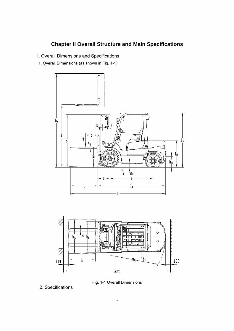
The brake pedal and clutch pedal (for mechanical forklift truck)/inching pedal (for hydraulic forklift truck) are combined together, as shown in Fig. 2-9. The brake pedal transfers the foot power acting on the pedal itself into brake oil pressure through the push rod of brake master cylinder.
1. Brake pedal 2. Clutch pedal (inching pedal) 3. Limit bolt 4. Brake sensor 5. Brake support 6. Brake master cylinder
Fig. 2-9 Brake Pedal Assembly
2.3 Brake Master Cylinder (Fig. 2-10)
The brake master cylinder comprises a valve seat, a one-way valve, a return spring, the main cup, the piston and the auxiliary cup. The end of the master cylinder is fixed by the thrust washer and stop wire. Its outer part is protected by a rubber dust-proof cover. The master cylinder piston acts through the brake pedal and push rod. When the brake pedal is pressed down, the push rod pushes the piston forward, and the brake fluid in the master cylinder flows back to the oil reservoir through the oil-return port till the main cup blocks up the port. Once the main cup overrides the port, the brake fluid in the front master cylinder chamber is compressed and opens the one-way valve to flow to the brake wheel cylinder through the brake pipeline. In this way, the piston in each wheel cylinder extends outward to make the brake shoe friction lining be in contact with the brake drum, so as to realize deceleration or braking. At this time, the rear piston chamber is filled up with the brake fluid from the oil-return port and oil-inlet port. When the brake pedal is released, the piston is pressed by the return spring. Meanwhile, the brake fluid in each brake wheel cylinder is compressed by the brake shoe return spring. Thus, the brake fluid returns to the master cylinder (front piston chamber) through the one-way valve and the piston returns to the original position. The brake fluid in

21
master cylinder flows to the oil reservoir through the oil-return port. The pressure of one-way valve is adjusted in proportion to the residual pressure in the brake pipeline and brake wheel cylinder, so as to ensure the brake wheel cylinder cup is set properly against oil leakage and to eliminate the air lock in emergency braking.
Fig. 2-10 Brake Master Cylinder
2.4 Brake
The brake is a two-shoe brake. The brakes are mounted at both sides of the drive axle. The brake comprises 2 sets of brake shoes, brake wheel cylinders and adjustors. One end of the brake shoe is in contact with the fixing pin, and the other end is in contact with the adjusting device. The brake controls the parking brake part by the return spring and spring pull rod. Besides, the brake is also set with a parking braking mechanism and an automatic adjusting device. (See Fig. 2-11)
1. Brake back plate assembly 2. Slack adjuster 3. Friction lining assembly 4. Elastic washer 5. Hand brake pull rod 6. Return spring 7. Washer 8. Ram 9. Return spring 10. Hand brake push rod 11. Compression spring 12. Adjusting rod 13. Spring seat 14. Spring 15. Spring cover 16. Spring 17. Spring seat 18. Spring pull rod 19. Support pin 20. Washer 21. Rubber plug 22. Brake cable assembly 23. Bolt M8×16 24. Spring washer 8 25. Brake wheel cylinder 26. Shroud 27. Pston ram 28. Piston 29. Brake wheel cylinder cup 30. Spring 31. Oil plug 32. Bleed screw 33. Screw shroud 34. Dust-proof cover
Fig. 2-11 Brake (1) Action of Brake The brake wheel cylinder provides the main and auxiliary brake shoes the same force to press against the brake drum. When the upper part of auxiliary brake shoe reaches the fixing
1. Connecting rod 2. Push rod 3. Dust-proof cover 4. Elastic retainer ring 5. Auxiliary cup 6. Piston 7. Main cup 8. Spring 9. One-way valve

22
pin, the main brake shoe will move towards the rotation direction of the brake drum. Once it reaches the fixing pin, the friction force between the friction lining and brake drum increases. As the main brake shoe gives the auxiliary brake shoe a larger force than that from the brake wheel cylinder, a large braking force is produced. See Fig. 2-12. The braking action in the course of reversing is the reverse. See Fig. 2-13.
Fig. 2-12 Action in Forwarding Fig. 2-13 Action in Reversing
(2) Parking Brake The parking brake is fit in the wheel brake. It comprises the pull rod and push rod. The pull rod is set at the main brake shoe side with a pin. The action of pulling is transferred to the auxiliary brake shoe side through the push rod. See Fig. 2-14. (3) Slack self-adjuster The slack self-adjuster may keep a proper clearance between the friction lining and the brake drum. Its structure is as shown in Fig. 2-15. It only acts in the course of reversing.
Fig. 2-14 Parking Brake Fig. 2-15 Slack Self-adjuster
(4) Action of Slack Self-adjuster When braking is applied in reversing traveling, the auxiliary brake shoe will be in contact and rotate with the main brake shoe to make the pull rod rotate clockwise around point A, as shown in Fig. 2-13. At this moment, point B will be lifted. Once the brake is released, the pull rod will rotate anti-clockwise under the effect of spring force, and point B will be lowered. As the clearance between the friction lining and brake drum increases, the vertical distance of rotating point B increases. As the adjuster is shifted to position I, the adjusting rod becomes longer (see Fig. 2-16) and the clearance decreases. The adjusting range of clearance is 0.40mm~0.45mm. 2.5 Parking Brake Controls (Fig. 2-17) The parking brake handle is a cam type handle. The adjuster at the top of the brake handle is used to adjust the braking force. Method to adjust the braking force: rotate the adjuster clockwise to increase the braking force;
1. Pin 2. Pull rod 1. Adjuster 2. Spring 3. Main brake shoe 4. Auxiliary brake shoe 3. Cable 4. Guide groove 5. Supporting rod 5. Pull rod
Main brake shoe Main brake shoe
Auxiliary brake shoe
Auxiliary brake shoe

23
rotate the adjuster anti-clockwise to reduce the braking force. Pulling force: 196N~294N
Fig. 2-16 Slack Self-adjuster Fig. 2-17 Parking Brake Handle
2.6 Disassembly/Assembly and Adjustment of Brake
The disassembly, assembly and adjustment of the brake as well as the adjustment of the brake pedal (the wheels and hub are dismounted) are as follows.
2.6.1 Disassembly of Brake
(1) Remove the support pin, adjusting rod, adjuster and spring from the auxiliary brake shoe. See Fig. 2-16.
(2) Remove the return spring on the brake shoe. See Fig. 2-19.
Fig. 2-18 Fig. 2-19
(3) Remove the fixing spring on the main brake shoe. See Fig. 2-20. (4) Remove the main and brake shoes. At the same time, remove the adjuster and its spring.
See Fig. 2-21.
Extending along this direction
Hand brake cable
Hand brake

24
Fig. 2-20 Fig. 2-21 (5) Remove the brake pipe from the brake wheel cylinder. Then take off the mounting bolt
from the brake wheel cylinder. Remove the brake wheel cylinder from the brake back plate. See Fig. 2-22.
(6) Take off the E-shaped retainer ring fixing the brake cable from the brake back plate. After that, remove the bolt on the back plate. Remove the brake back plate from the drive axle. See Fig. 2-23.
Fig. 2-22 Fig. 2-23
(7) To disassemble the brake wheel cylinder: take off the dust-proof ring; press one side of the piston to pry up the other side of piston; press this side of the piston by hand. See Fig. 2-24.
Fig. 2-24
2.6.2 Inspection of Brake
The inspection of parts and the repair/replacement of the damaged parts are as follows. (1) Check the inner surface of brake wheel cylinder block and the outer surface of piston for rust. Measure the clearance between the piston and cylinder block. Standard value: 0.03mm - 0.10mm; limit value: 0.15mm. (2) Visually check the piston cup for damage and deformation; if any, replace it. (3) Measure the free length of brake wheel cylinder spring. If it exceeds the standard value,
replace it. (4) Measure the thickness of friction lining. If it is exceeds the wear limit, replace it. See Fig.
2-25. Standard value: 8.0mm; limit value: 2.0mm. (5) Visually check the inner surface of brake drum. Grind it in case of damage or eccentric
wear. Replace it in case the wear exceeds the limit. Standard value: 314mm; limit value: 316mm. See Fig. 2-26.
Fig. 2-25 Fig. 2-26
2.6.3 Assembly of Brake
(1) Coat the brake wheel cylinder cup and piston with brake fluid. Fit the spring, piston cup,

25
piston and dust-proof ring successively. (2) Fit the brake wheel cylinder on the brake back plate.
(3) Fit the brake back plate on the drive axle. (4) Apply heat-resistant grease on the points as
shown in Fig. 2-25. Do not apply grease on the friction lining.
(a) The contact surface between back plate and brake shoe;
(b) The fixing pin; (c) The contact surface between brake shoe and
spring seat; (d) The hand brake pull rod support pin; (e) The screws of adjuster and other rotating parts. Fig. 2-27
(5) Fix the parking brake cable with the E-shaped retainer ring. (6) Fit the brake shoe with a fixing ring, see Fig. 2-28. (7) Fit the compression spring on the hand brake push rod. Fit the push rod on the brake shoe.
See Fig. 2-29.
Fig. 2-28 Fig. 2-29
(8) Fit the brake shoe guide plate on the support pin. Mount the brake shoe return spring. Fit the main brake shoe and auxiliary brake shoe successively. See Fig. 2-30.
(9) Fit the adjuster, adjuster spring, ram and ram return spring. Pay attention to the following: (a) The direction of adjuster screws and its installation direction;
(b) The direction of adjuster spring (no contact between adjuster gear teeth and spring); (c) The direction of ram return spring (the spring hook at the support pin side fixed at the
opposite side of ram); (d) The lower part of adjusting rod should be in contact with the adjuster gear teeth.
(10) Connect the brake oil pipe with the brake wheel cylinder. (11) Measure the inner diameter of brake drum and the outer diameter of brake shoe friction lining. Adjust the adjuster to keep the difference between them within 0.3mm-0.5mm. See Fig. 2-31.
Fig. 2-30 Fig. 2-31
2.6.4 Test of Slack Self-adjuster (Fig. 2-32)
(1) First, make the diameter of brake shoe to be close to the specified value. Turn the adjuster by pulling the adjusting rod. Release the adjusting rod, and then the rod should return to its original position while the adjuster gear should not move.
Note: When the adjusting rod is released, the adjuster should still work normally if the adjuster

26
gear and adjusting rod return together. (2) If the adjuster fails to do the above action when you pull the adjusting rod, you should
conduct the following work: (a) Fit the adjusting rod, ram, ram spring and spring seat properly. (b) Check the ram return spring and adjuster spring for damage. Check the rotating of
adjuster gear. Check the meshing part of adjuster for excessive wear or damage. Check the adjusting rod and gear teeth for contact. Replace the damaged parts.
Fig. 2-32
2.7 Adjustment of Brake Pedal (Fig. 2-33 (a))
(1) Shorten the push rod. (2) Adjust the limit bolt of brake pedal to adjust its height, as shown in Fig. 2-33 (b). (3) Extend the push rod, till the front of push rod is in contact with the brake master cylinder
piston. After that, turn it back for 1-2 circles to ensure a free travel of pedal of 10mm-20mm. (4) Lock the push rod nut and pedal limit bolt/nut.
a b
Fig. 2-33 (5) Adjust the brake switch (see Fig. 2-34). (a) After adjusting the brake pedal height, loosen the
locking nut of brake switch. (b) Remove the plug to separate the cables. (c) Turn the switch to keep a clearance A=1mm. (d) Make sure the brake lamp is on when the brake pedal
is pressed down. (e) Lock the nut.
Fig. 2-34 Brake Lamp Switch 2.8 Fault Analysis (Table 2-7)
Table 2-7
制动踏板 Push rod Brake pedal Limit bolt Free travel
Pedal
Locking nut
Brake switch
27
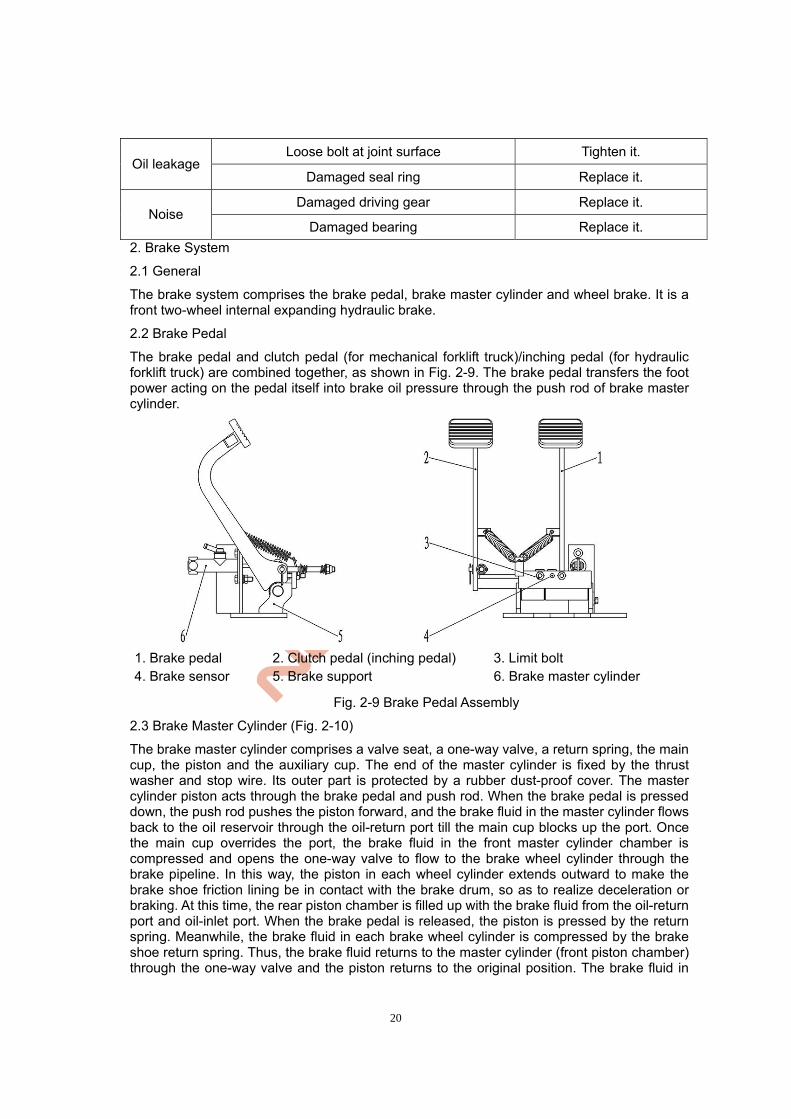
Symptom Possible Cause Remedy
1. Oil leakage in brake system Repair it.
2. Brake shoe clearance not set well Adjust slack adjuster.
3. Brake overheating Check for slipping.
4. Poor contact between brake drum and friction lining Readjust them.
5. Foreign substances on friction lining Repair or replace it.
6. Foreign substances in brake fluid Check it.
Poor braking
7. Brake pedal (inching valve) adjusted improperly Adjust it.
1. Hardened surface of friction lining or foreign substances on its surface
Repair or replace it.
2. Back plate distorted or loose bolt Repair or replace it.
3. Brake shoe distorted or improperly mounted Repair or replace it.
4. Friction lining worn out Replace it.
Noise at brake
5. Loose wheel bearing Repair or replace it.
1. Oil stain on surface of friction lining Repair or replace it.
2. Brake shoe clearance not set well Adjust slack adjuster.
3. Failed brake wheel cylinder Repair or replace it.
4. Damaged brake shoe return spring Replace it.
Uneven braking
5. Inclined brake drum Repair or replace it.
1. Oil leakage in brake system Repair or replace it.
2. Brake shoe clearance not set well Adjust slack adjuster.
3. Air in brake system Bleed it.
Insufficient
braking
4. Brake pedal adjusted improperly Re-adjust it.
2.9 Maintenance
① The new drive axle should be filled with gear oil before running-in. (Select the gear oil in strict accordance with the regulations in the Manual. Refer to Table 2-1 for the specific grade.) Fill oil from the oil filling port on the upper of axle housing, till there is oil overflows from the oil level port at the middle of the axle housing.
② The thickness of the brake shoe friction lining should be 8mm. The allowable min. thickness is 2mm. These two parts are critical parts of brake system. Check them once a week. Replace them in case of excessive wear, otherwise, accident may occur.
③ Maintenance after 50h of operation: I. Change the gear oil for the new axle after the machine has worked for 50 hours. Before oil
change, clean the inner part of the axle. II. Check each fastener for loose. If any, tighten it. III. Check the connection between the wheel half axle and hub for oil leakage. If any, apply
sealant again. ④ Monthly maintenance:

28
I. Check the brake drum for damaging wear. II. Check the brake shoe for wear. If it is worn out to the limit, replace it at once. III. Check the oil level in the axle housing. If it is low, fill oil in time.
⑤ Maintenance every 6 months: change the gear oil in the axle every half year. ⑥ Yearly maintenance: carry out inspection under disassembled condition every year. ⑦ Notes on inspection and test during assembly:
When refitting the drive axle hub, pay attention to the slack adjuster and keep the clearance between the brake drum and friction lining within 0.3mm~0.5mm. Fill 100ml of 3# lithium-based grease into the tapered roller bearing on the hub. Adjust the clearance of wheel hub bearing: tighten the inner locking nut till the hub brake drum can hardly rotate; turn the inner locking nut back for 1/8 circle till the hub brake drum can rotate freely without any seizure, obvious axial clearance or deflection; fit the locking washer; fix the outer locking nut. 3. Steering System
3.1 General
The steering system (Fig. 2-35) mainly comprises the steering wheel, steering shaft, steering gear, steering pump and steering axle. The steering shaft is connected to the steering gear by the universal joint. The connecting shaft is connected to the steering wheel by the universal joint. The steering column may tilt forward/backward to the proper position. The steering axle is mounted on the tail rack at the rear of the frame, with a steering knuckle fit at each side. The steering cylinder piston rod drives the steering knuckles to steer through the connecting rod. The steering knuckle leads the turning wheel to turn. Thus, the steering is realized. 3.2 Cycloidal Full Hydraulic Steering Gear
The full hydraulic steering gear (Fig. 2-36) may, according to the turning angle of steering wheel, metrically deliver the pressure oil from the steering pump to the steering cylinder through the pipeline. When the steering pump fails to supply oil, manual steering will be applied. The steering gear comprises a general steering gear and a combination valve. The hole on the upper cover of combination valve is the system safety valve. Besides, a two-way overload valve is set in the valve body. Such overload valve may protect the parts against damage due to the high pressure in hydraulic system in case the wheel is subject to unexpected impact of external forces when the machine is traveling. The safety valve and two-way overload valve have already been adjusted by the factory. Do not adjust them at will.

29
1. Steering wheel assembly 2. Bearer 3. Sleeve 4. Set bolt 5. Bracket assembly 6. Rubber pad II 7. Steering column assembly 8. Steering gear 9. Locking nut 10. Lining pipe I 11. Spacer ring 12. Lining pipe II 13. Protective sleeve 14. Long bolt 15. Locking handle assembly 16. Rubber pad I 17. Set bolt
Fig. 2-35 Steering Device

30
1. Limit column 2. Valve body 3. Valve core 4. Universal driving shaft 5. Leaf spring 6. Connecting block 7. Rotor 8. Stator 9. Valve sleeve
Fig. 2-36 Cycloidal Full Hydraulic Steering Gear
3.3 Steering Axle
The steering axle adopts a box cross-sectional welding structure (Fig. 2-37). It comprises the steering axle body, steering cylinder, connecting rod, steering knuckle and turning wheel. The steering trapezoid mechanism employs a slider-crank mechanism. The steering cylinder piston rod drives the steering knuckles through the connecting rod to steer. The steering knuckle leads the turning wheel to turn. Thus, the steering is realized. The steering axle is fixed on the rear rack at the rear of the frame by the front and rear pins and fixing plate (i.e., bolts for shock pad). In this way, the axle body may swing around the axis pin. There is a steering knuckle at each side of the steering axle. The rear hub is mounted on the steering knuckle shaft by two tapered roller bearings. The wheel is fixed on the hub by the rim. The oil seal at the inner side of bearing may keep the grease in the hub and steering knuckle chamber.
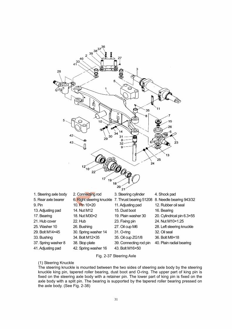
31
1. Steering axle body 2. Connecting rod 3. Steering cylinder 4. Shock pad 5. Rear axle bearer 6. Right steering knuckle 7. Thrust bearing 51208 8. Needle bearing 943/32 9. Pin 10. Pin 10×20 11. Adjusting pad 12. Rubber oil seal 13. Adjusting pad 14. Nut M12 15. Dust boot 16. Bearing 17. Bearing 18. Nut M30×2 19. Plain washer 30 20. Cylindrical pin 6.3×55 21. Hub cover 22. Hub 23. Fixing pin 24. Nut M10×1.25 25. Washer 10 26. Bushing 27. Oil cup M6 28. Left steering knuckle 29. Bolt M14×45 30. Spring washer 14 31. O-ring 32. Oil seal 33. Bushing 34. Bolt M12×35 35. Oil cup ZG1/8 36. Bolt M8×18 37. Spring washer 8 38. Stop plate 39. Connecting rod pin 40. Plain radial bearing 41. Adjusting pad 42. Spring washer 16 43. Bolt M16×50
Fig. 2-37 Steering Axle
(1) Steering Knuckle The steering knuckle is mounted between the two sides of steering axle body by the steering knuckle king pin, tapered roller bearing, dust boot and O-ring. The upper part of king pin is fixed on the steering axle body with a retainer pin. The lower part of king pin is fixed on the axle body with a split pin. The bearing is supported by the tapered roller bearing pressed on the axle body. (See Fig. 2-38)

32
1. Thrust bearing 2. Steering knuckle 3. Fixing pin 4. Steering knuckle adjusting pad 5. Steering knuckle king pin 6. Needle bearing 7. Rear axle bearer 8. Spring washer 9. Bolt
Fig. 2-38 (2) Steering Cylinder The steering cylinder is a double-acting piston type cylinder. Both sides of the piston rod are connected to the steering knuckles by the connecting rod. The pressure oil from the full hydraulic steering gear drives the piston rod to move left/right through the steering cylinder, so as to realize leftward/rightward steering. The piston adopts a combination seal of support ring and O-ring. The connection part of cylinder head and piston rod adopts an axial seal of Yx-ring. The cylinder is fixed on the steering axle by the cylinder heads at both ends. (See Fig. 2-39)
1. Piston rod assembly 2. Cylinder head 3. Dust-proof ring 50×72 4. U-ring 50×60×8 5. O-ring 63×3.55 6.O-ring 60×3.55 7. Support ring 8. Cylinder barrel assembly 9. Steel-backed bearing
Fig. 2-39 Steering Cylinder (3) Hub The hub is mounted on the steering knuckle by two tapered roller bearings. The wheel is fit on the hub by the rim. The oil seal at the inner side of bearing may keep the grease in the hub and steering knuckle chamber. The tightness of bearing may be adjusted by the nut. 3.4 Adjustment and Maintenance
(1) As shown in Fig. 2-40, fill grease in the hub, the inner/outer bearing and the inner of hub cover. Apply some grease on the oil seal lip as well.

33
(2) Fix the outer ring of bearing on the hub and fit the hub on the steering knuckle shaft. (3) Fit the plain washer and tighten the slotted nut with a torque of 206-235N.m (21-24kgm).
Loosen the slotted nut and tighten it again with a torque of 9.8N.m (1kgm). (4) Tap the hub with a wooden hammer and turn the hub for 3-4 circles to check it for
looseness. (5) Tighten the slotted nut and align the slot with the split pin hole on the steering knuckle. (6) Tap the hub with the wooden hammer again, turn the hub by hand for 3-4 circles to check it
for unstable rotation, and measure the rotating torque of hub which should be 2.94-7.8N.m (0.3-0.8kgm).
(7) When the rotating torque exceeds the specified value, turn the hub back for 1/6 circle and measure the rotating torque again.
(8) When the rotating torque reaches the specified value, lock the slotted nut with a split pin.
Fig. 2-40 Adjustment of Pre-tightening Load
3.5 Inspection of Steering System After Refitting
(1) Turn the steering wheel left/right to the end to see if the turning force is even and the turning is stable.
(2) Check the layout of pressure oil pipeline for reverse installation. (3) Jack up the rear wheels and slowly turn the steering wheel left/right for several times to
bleed the air in hydraulic pipeline and cylinder.
3.6 Fault Analysis (Table 2-8)
Table 2-8 Fault Analysis
Symptom Possible Cause Remedy
Damaged or failed oil pump Replace it. Steering wheel
not moving Damaged rubber hose/connector or blocked pipeline
Replace or clean it.
Low pressure in safety valve Adjust it.
Air in oil circuit Bleed it. Failed steering gear resetting; breakage or poor elasticity of positioning leaf spring
Replace leaf spring. Heavy turning of steering wheel
Large internal leakage in steering cylinder Check piston seal. Machine zigzag
driving or swinging
Breakage or poor elasticity of spring Replace it.
Low oil level in oil tank Fill oil. Large working noise Blocked oil suction pipe or oil filter Clean or replace it.
Oil leakage Damaged seal of steering cylinder guide sleeve or damaged pipeline/connector
Replace it.
Filling grease
34
4. Electrical System
4.1 General
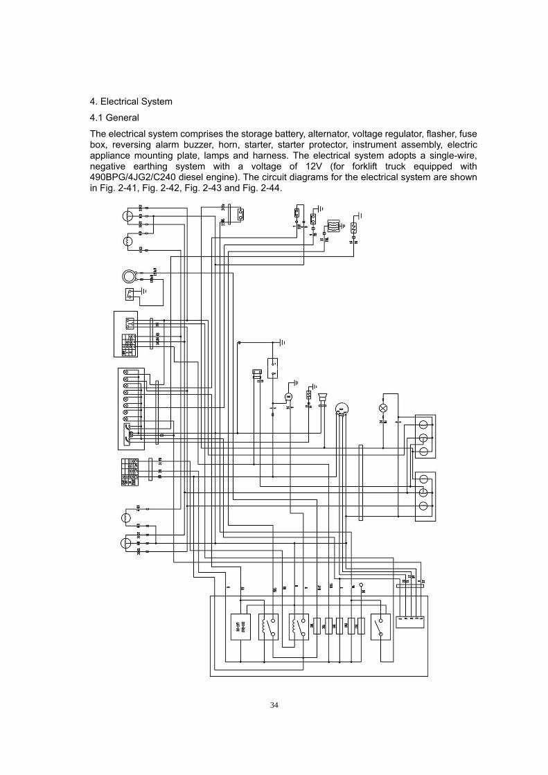
The electrical system comprises the storage battery, alternator, voltage regulator, flasher, fuse box, reversing alarm buzzer, horn, starter, starter protector, instrument assembly, electric appliance mounting plate, lamps and harness. The electrical system adopts a single-wire, negative earthing system with a voltage of 12V (for forklift truck equipped with 490BPG/4JG2/C240 diesel engine). The circuit diagrams for the electrical system are shown in Fig. 2-41, Fig. 2-42, Fig. 2-43 and Fig. 2-44.

35
Fig. 2-41 Electrical Schematic Diagram for Mechanical Forklift Truck with 490B Engine
Fig. 2-42 Electrical Schematic Diagram for Hydraulic Forklift Truck with 490B Engine

36
Fig. 2-43 Electrical Schematic Diagram for Hydraulic Forklift Truck with 4JG2 Engine

37
Fig. 2-44 Electrical Schematic Diagram for Hydraulic Forklift Truck with C240 Engine
4.2 Storage Battery
This forklift truck in this series adopts a dry charged storage battery (model: 6-QA-100). (1) Before initially using the dry charged storage battery, fill electrolyte, set the battery stand
38
still for 0.5h~1h and then tighten the filler plug. Generally, an initial charging should be conducted. See Table 2-9 for the current and time for initial charging.
Table 2-9 Current and Time for Initial Charging of Dry Charged Storage Battery Initial Charging
Model Qty./Machine Current (A) Time (h)
6-QA-100 1 5 About 5
(2) When the storage battery is fully charged, the electrolyte specific gravity is 1.260~1.285. When the electrolyte specific gravity drops to 1.150~1.180, you should stop using the storage battery and charge it.
(3) Keep the storage battery clean and the vent hole unblocked. Regularly clean the surface of storage battery witch clean water (instead of metal) and dry it, and then apply industrial Vaseline to protect the electrode poles.
(4) Regularly check the specific gravity and level of electrolyte. Generally, the electrolyte level should be 10mm~15mm higher than the protective plate. If the level is lower than the specified value, fill distilled water in time.
4.3 Alternator and Voltage Regulator
The forklift truck equipped with 490BPG diesel engine adopts JF11A alternator, with a rated voltage of 14V. The forklift truck equipped with 4JG2/C240 diesel engine adopts an alternator with a rated voltage of 12V and a rated current of 35A. The voltage regulator is connected in series in the exciting circuit of alternator. The alternator and voltage regulator work together to keep the output voltage at different engine speed within a certain range, so as to meet the requirements of electric appliances.
(1) After starting the engine, do not disconnect the alternator and storage batter; otherwise, the voltage may be out of control.
(2) Do not use screwdriver or other metals to short-circuit the armature point of alternator with the housing or negative pole to check if there is spark. Such method to determine whether the alternator works or not may easily damages the elements.
(3) Regularly clear the dust and oil stain on the surface of the alternator, esp. the terminal, so as to keep a good wiring. In case the alternator does not work, find out the cause and rectify it in time.
(4) Maintain the alternator after 100h of alternator operation: replace the worn electric brush, finish the surface of collector ring, and change the grease (3# composite calcium-based grease or 4# high temperature grease).
(5) The alternator is a negative earthing alternator. It is connected in parallel with the storage battery. The earthing poles should be consistent when the alternator is working. Otherwise, the rectifier diode in the alternator may be burnt out.
(6) After a certain period of engine operation, the charging current will gradually reduces, which indicates that the alternator and voltage regulator work normally. If the charging current keeps low or the charging fails, you should find out the cause and rectify it in time.
(7) The tension of V-belt should be proper. Too loose V-belt may lead to belt slipping and insufficient electricity generation. Too tight V-belt may speed up the wear of bearing. Generally, the tightness is acceptable if there is a vertical distance of 10mm~15mm when the belt is pressed down.
4.4 Starter and Starter Protector
The forklift truck equipped with 490BPG diesel engine adopts QD1315A starter, with a rated voltage of 12V and a power of 2.5kW. The model of the matching starter protector is JD133D. The forklift truck equipped with 4JG2 diesel engine adopts a starter with a rated voltage of 12V and a power of 2.2kW. The forklift truck equipped with C240 diesel engine adopts a starter with a rated voltage of 12V and a power of 2kW.
(1) Turn the starting ignition switch to “ON” position, then the starter protector acts and the
39
starter drives the engine to run. After the engine is started, the starter protector will automatically cut off the power to make the starter one-way clutch return to the original position.
(2) The starting time for starter should be no more than 10s, and the interval between two starting operations should be at least 2min.
(3) Regularly check the connecting wire of starter for looseness. Check the commutator and electric brush for poor contact. Every 1000h of operation, conduct maintenance: replace the excessively worn electric brush, finish the outer part of commutator, repair or replace the contact of electromagnetic switch and apply grease on the gear spline.
4.5 Instrument Assembly
The instrument panel comprises 7 signal indicator lamps and 3 instruments. The instrument accessories include the starting ignition switch, turn signal indicator lamp switch, fuel sensor, oil temperature sensor and water temperature sensor.
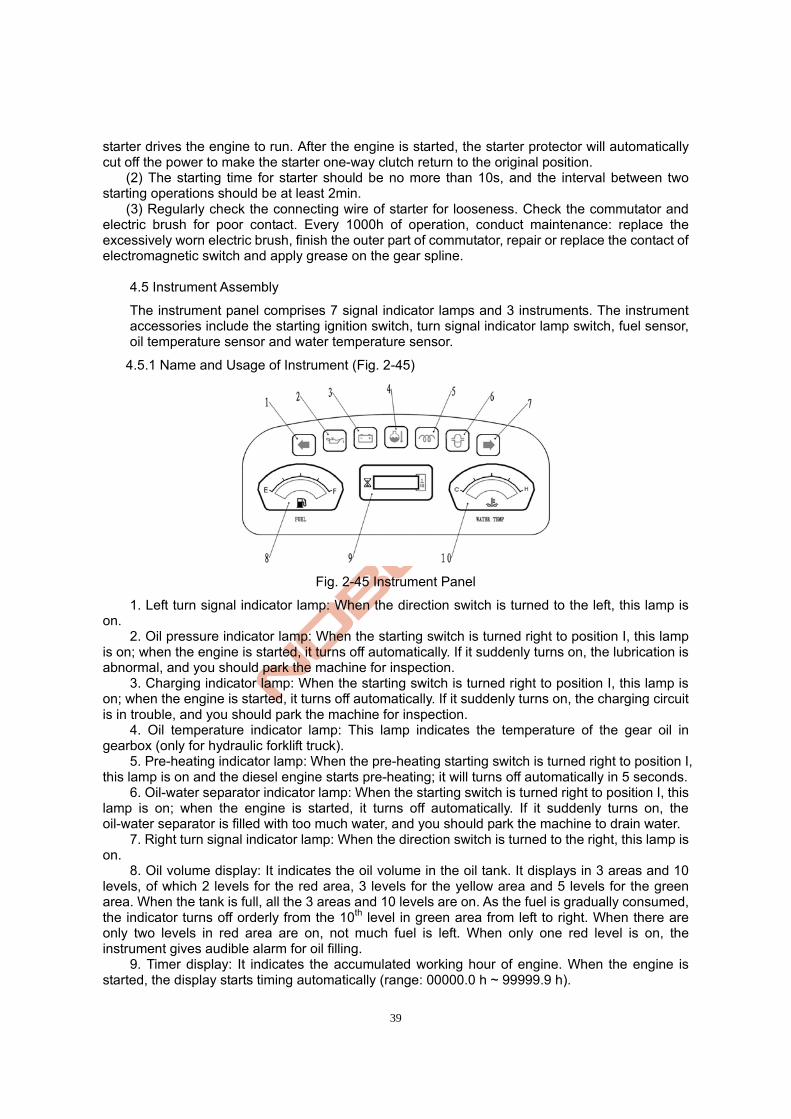
4.5.1 Name and Usage of Instrument (Fig. 2-45)
Fig. 2-45 Instrument Panel
1. Left turn signal indicator lamp: When the direction switch is turned to the left, this lamp is on.
2. Oil pressure indicator lamp: When the starting switch is turned right to position I, this lamp is on; when the engine is started, it turns off automatically. If it suddenly turns on, the lubrication is abnormal, and you should park the machine for inspection.
3. Charging indicator lamp: When the starting switch is turned right to position I, this lamp is on; when the engine is started, it turns off automatically. If it suddenly turns on, the charging circuit is in trouble, and you should park the machine for inspection.
4. Oil temperature indicator lamp: This lamp indicates the temperature of the gear oil in gearbox (only for hydraulic forklift truck).
5. Pre-heating indicator lamp: When the pre-heating starting switch is turned right to position I, this lamp is on and the diesel engine starts pre-heating; it will turns off automatically in 5 seconds.
6. Oil-water separator indicator lamp: When the starting switch is turned right to position I, this lamp is on; when the engine is started, it turns off automatically. If it suddenly turns on, the oil-water separator is filled with too much water, and you should park the machine to drain water.
7. Right turn signal indicator lamp: When the direction switch is turned to the right, this lamp is on.
8. Oil volume display: It indicates the oil volume in the oil tank. It displays in 3 areas and 10 levels, of which 2 levels for the red area, 3 levels for the yellow area and 5 levels for the green area. When the tank is full, all the 3 areas and 10 levels are on. As the fuel is gradually consumed, the indicator turns off orderly from the 10th level in green area from left to right. When there are only two levels in red area are on, not much fuel is left. When only one red level is on, the instrument gives audible alarm for oil filling.
9. Timer display: It indicates the accumulated working hour of engine. When the engine is started, the display starts timing automatically (range: 00000.0 h ~ 99999.9 h).
40
10. Water temperature display: It indicates the temperature of engine cooling water. It displays in 3 areas and 10 levels, of which 2 levels for the red area, 3 levels for the yellow area and 5 levels for the green area. When the temperature of cooling water is lower than 75 ℃, the 1st green level is on. As the water temperature gradually increases, the levels turn on orderly. When the 9th level in red area is on, the temperature of cooling water is too high. When the 10th level in red area is on, the instrument gives audible alarm, and you should stop using the machine. When the cooling water cools down till only the green levels are on, you can operate the machine again.
4.5.2 Starting Ignition Switch and Combination Switch
(1) The model of starting ignition switch is JK406. It is used for controlling the starter, pre-heater and other electric appliances. For the details of its working positions, see Table 2-10.
Table 2-10 Use of Starting Ignition Switch Position Function Position Function
III Pre-heating (anti-clockwise) I Working (clockwise) OFF Non-working II Engine starting (clockwise)
(2) Combination switch: model: JK804. It is used for controlling the turn lamp and lighting lamp. Pull the switch backward or push it forward to control the leftward/rightward steering of machine. There are two positions in clockwise direction. See Table 2-11 for the functions of all position.
Table 2-12 Positions and Functions of Lamp Switch Position Function
OFF Cutting off lamp power Position I
(clockwise) Switching on the front small lamp and rear width lamp
Position II (clockwise)
Switching on the headlamp
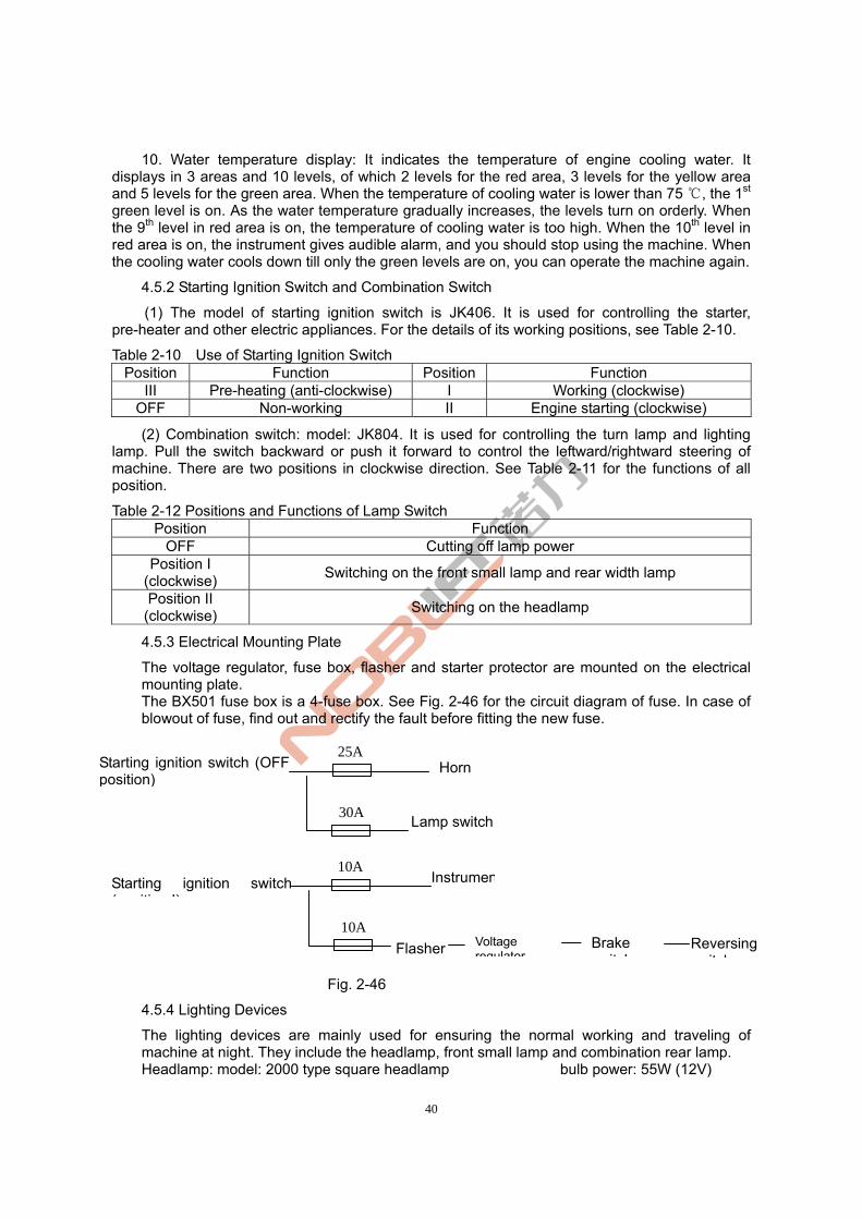
4.5.3 Electrical Mounting Plate
The voltage regulator, fuse box, flasher and starter protector are mounted on the electrical mounting plate. The BX501 fuse box is a 4-fuse box. See Fig. 2-46 for the circuit diagram of fuse. In case of blowout of fuse, find out and rectify the fault before fitting the new fuse.
图 2-46
Fig. 2-46
4.5.4 Lighting Devices
The lighting devices are mainly used for ensuring the normal working and traveling of machine at night. They include the headlamp, front small lamp and combination rear lamp. Headlamp: model: 2000 type square headlamp bulb power: 55W (12V)
Flasher
30A
25A Starting ignition switch (OFF position)
Horn
Lamp switch
Starting ignition switch ( iti I)
10A
10A Instrumen
Voltage regulator
Brake it h
Reversing it h

41
Front small lamp: model: TCM turn lamp (double-sided yellow square lamp) bulb power: 21W, 10W Combination rear lamp: model: 2000 type three-color tail lamp bulb power: 21W, 21W/5W, 21W
5. Hydraulic System 5.1 General
The hydraulic system comprises the working oil pump, multi-way valve, lifting cylinder, dump ram and pipeline. See Fig. 2-47. The hydraulic oil is supplied by the oil pump directly connected with the engine. The multi-way valve distributes the oil to each cylinder.
Fig. 2-47 Basic Diagram of Hydraulic System
5.2 Oil Pump
The oil pump is a gear pump.
Model Rotation Direction
Output (ml/r)Rated
pressure (MPa)
Rated rotation speed (r/min)
Matching engine
CBHZ-F32-ALHL Left 32 20 2500 490BPG
CBHZ-F32-ALφ Right 32 20 2500 ISUZU 4JG2
CBHZ-F32-ALφL Left 32 20 2500 ISUZU C240
5.3 Multi-way Valve
The multi-way valve is a two-plate four-part valve. The hydraulic oil from the working oil pump is controlled by the valve rod of multi-way valve and the high-pressure oil is distributed to the lifting cylinder or dump ram. The multi-way valve is set with a safety valve and a self-locking valve. The safety valve set at the upper part of the oil inlet port of multi-way valve controls the system pressure. The self-locking valve set on the inclined valve plate is mainly used to prevent the dump ram from mis-operating the control lever when there is no pressure source. There is a one-way valve respectively set between the oil inlet port and the oil suction port of lifting valve plate as well as between the oil inlet port of lifting valve plate and the oil inlet port of titling valve plate.
Multi-way valve
Steering cylinder Dump ram
Lifting cylinder
Cycloidal steering valve
Including the integralvalve
Priority valve
Gear pump
Set in the lifting cylinderGovernor valve

42
The outline of multi-way valve is as shown in Fig. 2-48.
Fig. 2-48 Outline of Multi-way Valve
(1) Operation of Slide Valve (taking tilting slide valve for example) (a) Neutral Position (Fig. 2-49)
The high-pressure oil from the oil pump flows back to the oil tank through the neutral position. (b) Pushing Slide Valve (Fig. 2-50).
Close the middle passage, and then: the oil from the oil inlet port opens the one-way valve to flow to oil cylinder port B; the oil from oil cylinder port A flows to the oil tank through the low-pressure passage and make the slide valve back to the neutral position with the help of return spring.
Fig. 2-49 Fig. 2-50
(c) Pulling Slide Valve (Fig 2-50) Close the neutral position, and then: the oil from the oil inlet port opens the one-way valve to flow to oil cylinder port A; the oil from oil cylinder port B flows to the oil tank through the low-pressure passage and make the slide valve back to the neutral position with the help of return spring. (2) Action of Safety Overflow Valve (Fig. 2-51) An overflow valve is set between the oil pump port “HP” and low–pressure passage “LP”. The oil flowing through the lifting valve “C” acts on different areas of diameters “A” and “B”. In this way, the one-way valve “K” and overflow lifting valve “D” will be set on the valve seat. The pressure regulated in the oil pump passage “HP” acts on the guide valve spring, and then the one-way valve “E” opens. The oil flows to the low-pressure passage “LP” side through the holes around the valve. Once the guide valve “E” is open, the pressure in valve “C” will drop and the valve “E” and valve “C” will be set on the valve seat. The fluid flowing to the rear of valve “D” will be cut off. Thus, the pressure in the valve will be reduced. The pressure at the oil pump passage “HP” side and the inner pressure are not balanced, so the valve “D” will be under the effect of pressure difference, and the oil will directly flow to the low-pressure circuit "LP".
Middle passage Low-pressure passage
Slide valve
Return spring
Oil cylinder port A
Oil inlet one-way valve
Oil cylinder port B
Oil inlet port

43
Fig. 2-51
(3) Action of Tilting Self-locking Valve A tilting self-locking valve is set in the valve plate of dump ram. Such self-locking valve is adopted to prevent the mast from sudden dropping and to prevent danger due to the mis-operation of tilting valve rod when there is negative pressure produced in the oil cylinder. With such self-locking valve, the mast will not tilt forward even you push the control lever forcibly when the engine is stopped. The oil flow when the valve core is pulled out is the same with that in Fig. 2-51. At this moment, the mast is tilted backward. (a) When the valve core is pushed (pump working), the oil from the main pump flows to the
dump ram through port “B”, and the oil returning from the oil cylinder acts on the piston through port A. The oil flows to the low-pressure passage through holes A and B on the valve core and returns to the oil tank. See Fig. 2-52.
(b) When the valve core is pushed (pump not working), no oil flows into oil cylinder port “B”, so the pressure at P will not increase. Thus, the piston will not move and the oil from oil cylinder port “A” will not return to the oil cylinder and the oil cylinder will not move. See Fig. 2-53.
Fig. 2-52 Fig. 2-53
(4) Operation of Multi-way Valve (Fig.2-54) The multi-way valve is controlled by the control lever. All control levers are fit on a connecting shaft which is fixed on the vehicle body by a bracket. The control lever controls the slide valve through the connecting rod.
Port A Port B
Self-locking valve
○A ○B
Port A Port B
Self-locking valve
○A ○B
○P

44
多路阀
起升操纵杆
倾斜操纵杆
属具操纵杆
Fig. 2-54 Control of Multi-way Valve
(5) Adjustment of Pressure in Safety Valve The setting pressure of safety valve is 17.5 MPa (FD20/25(T)) or 20MPa(FD30/35(T)).
The pressure of safety valve has already been adjusted by the factory. Do not adjust it at will.
5.4 Lifting Cylinder and Lifting Chain (Fig. 2-55)
The lifting cylinder is a single-acting piston type cylinder. It comprises the cylinder block, piston rod, piston, and cylinder head. The two lifting cylinders of the forklift truck in this series are mounted at the rear of the external mast. The bottom of the cylinder is fixed on the lifting cylinder bearer at the external mast with pins and bolts. The top of the cylinder (i.e., the top of piston rod) is connected with the upper cross beam of external mast. A governor valve is set in the right lifting cylinder. The piston is fixed on the piston rod with an elastic wire. The outer part of piston is set with an oil seal and a support ring. A cut-off valve is set at the bottom of the cylinder. It may prevent against accident due to the sudden breakdown of high-pressure pipe when the mast is lifted. A steel-backed bearing and an oil seal are mounted on the cylinder head. They are respectively used to support the piston ring and to prevent the cylinder from dust.
Lifting control lever
Tilting control lever
Multi-way valve
Attachment control lever

45
Left Lifting Cylinder Right Lifting Cylinder
1. Dust-proof ring 2. Shaft seal 3. Cylinder head 4. O-ring 5. Steel-backed bearing 6. Left cylinder block 7. Piston rod 8. Adjusting sleeve 9. O-ring 10. Spring 11. Steel wire retainer ring 12. Spring seat 13. Piston 14. Support ring for hole 15. Buffer valve core 16. Retainer ring 17. Hole seal 18. One-way valve 19. Circlip for hole 20. Cut-off valve 21. O-ring 22. Governor valve 23. O-ring 24. Split pin 25. Chain connector 26. Nut 27. Chain 28. Sprocket wheel
Fig. 2-55 Lifting Cylinder and Chain ■ Operation of Cut-off Valve A cut-off valve is set at the bottom of lifting cylinder (as shown in Fig. 2-56). If the high-pressure hose breaks down suddenly, the materials lifted may be dropped down rapidly. The oil from lifting cylinder flows through the slide valve of cut-off valve and then the oil holes around the slide valve may produce a certain pressure difference between the two chambers. When the pressure difference is lower than the spring force, the slide valve may stop moving. Whereas, when the high-pressure hose breaks, a large pressure difference may be produced and the slide valve may move to block the oil holes round it. In this way, only little oil may flow through the small holes at the end of the slide valve, and the fork will be lowered slowly.

46
1. Lifting cylinder 2. Pressure spring 3. Valve core
Fig. 2-56 Cut-off Valve 5.5 Governor Valve
The governor valve is mounted in the right lifting cylinder. It controls the lowering speed of fork and prevents against accidents due to the unexpected sudden breakdown of high-pressure pipe, etc. See Fig. 2-57 for its connection.
1. Lifting cylinder block 2. Valve core 3. Pressure spring 4. Plug screw
Fig. 2-57 Built-in Governor Valve
5.6 Dump Ram
The dump ram is a double-acting cylinder. Its piston rod is connected to the mast with an eye ring. The bottom of dump ram is connected with the frame with pins. The machine is set with a dump ram at each side. The dump ram mainly comprises the piston, piston rod, cylinder block, cylinder bottom, guide sleeve, and seals. The piston and piston rod are of welded structure. The outer part of piston is set with a bearing and two Yx-rings. The inner hole of guide sleeve is set with a shaft sleeve and a Yx-ring, a retainer ring and a dust-proof ring. The shaft sleeve supports the piston rod. The Yx-ring, retainer ring and dust-proof ring may prevent against oil leakage and dust. They are fit on the cylinder block together with the O-ring. See Fig. 2-58. When the dump ram slide valve is pushed forward, the high-pressure oil enters from the bottom of cylinder to push the piston forward and make the mast tilt forward. When the slide valve is pulled backward, the high-pressure oil enters from the front of cylinder block to push the piston backward and make the mast tilt backward.
Normal Condition Cut-off Condition

47
1. Dust-proof ring 2. Circlip for hole 3. Retainer 4. Retainer 5. Shaft sleeve 6. Cylinder head 7. O-ring 8. Steel-backed bearing 9. Cylinder block 10. Support ring 11. Retainer 12. Hole seal 13. Steel-backed bearing 14. Adjusting sleeve 15. O-ring 16. Piston 17. Piston rod 18. Eye ring 19. Joint bearing
Fig. 2-58 Dump Ram 5.7 Hydraulic Pipeline
The hydraulic oil pipeline of hydraulic system is shown in Fig. 2-59.

48
1. Rubber hose (front) 2. Rubber hose 3. Dump ram oil pipe I 4. Dump ram oil pipe II5. Pipe clamp 6. Spring washer 7. Bolt 8. Combination washer9. Connector 10. Connector I 11. Oil return pipe 12. Clamp 13. Pipe 14. connector 15. O-ring 16. Gear pump 17. Spring washer 18. Bolt 19. O-ring 20. Connector 21. Pump oil suction pipe 22. Connector 23.OIL pipe 24. Connector I 25. Connector 26. Oil Pipe 27. Connector 28. Oil pipe 29. Steering gear oil return pipe 30. Clamp 31. Combination washer
Fig. 2-59 Hydraulic Pipeline 5.8 Maintenance and Adjustment
Maintenance of Working Oil Pump (1) Disassembly Before disassembly, completely clean the pump. Put the dismounted parts on a piece of clean paper or cloth. Be careful! Do not get the parts dirty or damaged.
(a) Clamp the flange part of pump on the bench. (b) Remove the connecting bolt 11, rear end cover 5 and pump body 1. (c) Take off the liner plate 6, driving gear 2 and driven gear 3.
Tilting cylinder
Tilting cylinder
Steering gear
Steering cylinder
Multi-way valve
Oil tank
Pump

49
(d) Remove the seal ring 7 and retainer ring 8 from the front and rear end covers. Note: if the seal ring is not to be replaced, do not remove it from the front end. (2) Inspection Check the dismounted parts and clean them with gasoline (except the rubber parts). (a) Inspection of Pump Body
If the contact length between the inner part of pump and the gear is 1/2 times longer than the circumference, replace the pump body.
Fig. 2-60 Fig. 2-61
(b) Inspection of Liner Plate Check the contact surface of liner plate. If its contact surface is damaged, or its thickness is lower than the specified value, replace it. Standard thickness of liner plate: 4.94mm.
Fig. 2-62 Fig. 2-63
(c) Inspection of Front/Rear Pump Cover If the color change (brown) of the inner surface of bushing exceeds 150°, replace the pump cover. (d) Inspection of Driving/Driven Gear
In case of excessive wear, replace the gear in pair. If the value D is lower than the specified value, repair the gear in pair.
Fig. 2-64
(e) Replace the seal ring, bushing seals, retainer ring, oil seal and elastic retainer ring as required.
(3) Assembly (a) Fit the new seal ring and retainer ring on the front end cover of pump. (b) Fit the liner plate on the groove of front end cover. Do not mix up the oil suction port and
oil drain port. (c) Fit the driving gear and driven gear on the front end cover.
Oil inlet
Oil outlet
Liner plate Groove
Oil drain port side
Oil suction port side
12.7(0.5)
12.7(0.5)
D D

50
(d) Fit the liner plate on the gear side, and align the groove with the gear point. Do not mix up the oil suction port and oil drain port.
(e) Fit the new seal ring and retainer ring on the groove of rear end cover. See Fig. 2-63. (f) Fit the rear end cover on the pump body. Do not mix up the oil suction port and oil drain
port. (g) After that, tighten the connecting bolt with a torque of 9~10kg.m.
1. Pump body 2. Driving gear 3. Driven gear 4. Front end cover 5. Rear end cover 6. Liner plate 7. Seal ring 8. Retainer ring 9. Oil seal 10. Elastic retainer ring 11. Bolt 12. Washer
Fig. 2-65 Gear Pump
(4) Test Run
Conduct a test run to run in the oil pump and check its operation. It is better to do a pump test on bench. However, it is also acceptable to do a test on the machine according to the following procedures:
(If the oil pump is excessively worn out or stuck due to hydraulic oil and disassembled for repair, change the hydraulic oil and oil filter before the test run on the machine.)
(a) Fit the pump on the machine and than fit a pressure gauge on the pressure testing port of multi-way valve. (b) Loosen the adjusting screw of overflow valve and run the pump at a rotation speed of 500-1000rpm for about 10min. Make sure the oil pump is lower than 10kg/cm². (c) Run the pump at a rotation speed of 1500-2000rpm for about 10min. (d) Maintain the pump rotation speed at 1500-2000rpm for about 5min and increase the pressure by 20-30kg/cm² each time till it reaches 175kg/cm². After that, run each oil circuit for 5min and replace the return oil filter.
When the oil pressure is increased, check the oil temperature, the temperature of pump surface and the operation sound. In case of large increase in the oil temperature or the temperature of pump surface, reduce the loads to lower the temperature before continuing the test.
(e) After test, keep the overflow pressure at 175kg/cm² and measure the flow by the lifting speed.
5.9 Fault Analysis

51
In case of fault in hydraulic system, find out the cause and conduct the necessary remedy according to the following table.
(1) Fault Analysis of Multi-way Valve (Table 2-13) Table 2-13
Symptom Cause Remedy
Slide valve stuck Clean it after disassembly. Failure to increase pressure in lifting oil circuit Oil hole blocked Clean it after disassembly.
Slide valve stuck Clean it after disassembly. Vibration Slow pressure increase Insufficient air bleed Bleed air.
Slide valve stuck Clean it after disassembly. Pressure in steering oil circuit higher than specified value Oil hole blocked Clean it after disassembly. Failure to reach specified oil level
Improper adjusting of overflow valve
Adjust it.
Improper adjusting of overflow valve
Adjust it. Noise
Wear at sliding face Replace overflow valve.
Oil leakage (external) Aged or damaged O-ring Replace it.
Damaged spring Replace it. Low setting pressure
Damaged valve seat surface Adjust or replace overflow valve.
Oil leakage (internal) Damaged valve seat surface Finish valve seat surface.
High setting pressure Valve stuck Clean it after disassembly.
(2) Fault Analysis of Oil Pump (Table 2-14) Table 2-14
Symptom Cause Remedy
Low oil level in oil tank Fill oil to specified level. Small oil drained
Oil pipe or oil filter blocked Clean or replace it as required. ● Damaged liner plate ● Damaged bearing ● Poor sealing of seal ring, bushing seal or retainer ring
Replace it.
Improper adjusting of overflow valve
Adjust pressure in overflow valve to specified value by a pressure gauge.
Low pressure in pump
Air in hydraulic system ● Re-tighten oil pipe at oil suction side. ● Fill oil. ● Replace oil pump seal.
Damaged oil suction pipe or blocked oil filter
Check pipe or repair oil filter
Air leakage at loose oil suction side
Tighten loose part.
High oil viscosity Change oil with proper viscosity according to pump temperature.
Noise during operation
Bubble in oil Find out cause and rectify it. Damaged oil seal or seal ring of pump
Replace it. Oil leakage at pump
Damaged pump Replace it.

52
6. Lifting System 6.1 General
The lifting system uses a two-stage roller structure for vertical lifting. It comprises the internal mast, external mast and fork arm carrier.
6.2 Internal/External Mast (Fig. 2-66)
The internal and external masts are welded parts. The bottom of external mast is fixed on the drive axle by a support.
The middle of external mast is connected to the frame by the dump ram. With the help of dump ram, the external mast may tilt forward/backward.
1. Internal mast 2. Guide plate 3. Adjusting pad 4. External mast 5. External mast flat roller 6. Dump ram axis pin 7. Spring washer 8. Bolt 9. Oil cup 10. Bearing shell 11. Bearer cover 12. Spring washer 13. Bolt 14. Contact roller
Fig. 2-66 Internal/External Mast

53
6.3 Fork Arm Carrier (Fig. 2-67)
The fork arm carrier moves within the internal mast through the main roller. The main roller is mounted on the main roller shaft by elastic retainer rings. The main roller shaft is welded on the fork arm carrier. The side roller is integrated on the composite roller which is adjustable and rolls along with the flange plate of internal mast. To avoid rolling clearance, 2 fixed side rollers are used to roll along with the outer part of the flange plate of internal mast. The main roller bears the longitudinal loads. When the fork is lifted to the top, the roller exposes from the top of mast. The side roller bears the lateral loads.
1. Backrest 2. Plain washer 14 3. Spring washer 14 4. Bolt 5. Contact roller 6. Circlip for shaft 7. Composite roller 8. Fork arm carrier 9. Fork assembly
Fig. 2-67 Fork Arm Carrier
6.4 Position of Contact Roller (Fig. 2-68)
There are two kinds of contact roller: the composite contact roller for external mast and the composite contact roller for internal mast/fork arm carrier. They are respectively mounted on the external mast, internal mast and fork arm carrier. The composite contact roller is made up of the main roller and side roller. The former bears the load at front/rear direction. The latter bears the lateral load to ensure the free movement of internal mast and fork arm carrier.

54
1. Fork arm carrier 2. External mast 3. Composite contact roller for external mast 4. Internal mast 5. Composite contact roller for internal mast/fork arm carrier
Fig. 2-68 Position of Contact Roller Note: (a) The clearance of side roller: 0.5mm;
(b) Apply grease on the surface of main roller and the contact surface of mast. 6.5 Maintenance and Adjustment
6.5.1 Adjustment of Lifting Cylinder (Fig. 2-69)
When dismounting or replacing the lifting cylinder, internal mast or external mast, you should also re-adjust the stroke of lifting cylinder according to the following procedures:
(1) Fit the head of piston rod (without adjusting pad) on the upper cross beam of internal mast. (2) Slowly lift the mast till the cylinder stroke reaches the maximum value. Check if the two
cylinders are synchronized. (3) Fit an adjusting pad between the head of piston rod and the upper cross beam of internal
mast. The thickness of adjusting pad should be 0.2mm~0.5mm. (4) Adjust the tightness of chain.
1. Upper cross beam of internal mast 2. Adjusting pad of lifting cylinder 3. Lifting cylinder
Fig. 2-69 Adjustment of Lifting Cylinder
6.5.2 Height Adjustment of Fork Arm Carrier (Fig. 2-70)
(1) Park the machine on a level ground and keep the mast vertical. (2)Keep the bottom of fork be in contact with the ground. Adjust the adjusting nut on the
upper end connector of chain to set a distance A (A=24~29) between the main roller and the lower end of mast.
Fig. 2-70
(3) Lower the fork on the ground and tilt it backward in position. Adjust the adjusting nut on the upper end connector of chain to ensure the equal tightness of the two chains.
6.5.3 Replacement of Contact Roller for Fork Arm Carrier
(1) Put a pallet on the fork and park the machine on a flat ground.
Fork
Main roller
Fork arm carrier
Internal mast
Tyre

55
(2) Lower the fork and pallet on the ground. (3) Remove the upper end connector of chain and take off the chain from the sprocket wheel.
(4) Lift the internal mast ( in Fig. ① 2-71). (5) Confirm the fork arm carrier is separated with the external mast. Drive the machine back
(② in Fig. 2-71). (6) Replace the main roller. (a) Remove all elastic retainer rings and use a puller to take off the main roller. Do not
remove the adjusting pad. (b) Make sure the new roller is the same with the old one. Fit the new roller on the fork arm carrier and fix it with elastic retainer rings.
Fig. 2-71 Fig. 2-72
6.5.4 Replacement of Contact Roller for Mast (Fig. 2-72)
(1) Remove the fork arm carrier from the internal mast in the way as described in 7.5.3. (2) Park the machine on a flat ground and pad up the front wheels for 250-300mm. (3) Pull up the hand brake lever and pad up the rear wheels with wedge blocks. (4) Remove the bolt fixing the lifting cylinder and internal mast. Lift the internal mast. Properly
keep the adjusting pad at the head of piston head. (5) Remove the bolt fixing the lifting cylinder and the bottom of external mast. Remove the oil cylinders and the oil pipe between them. Do not loosen the oil pipe connector.
(6) Lower the internal mast and remove the main roller at its bottom. The main roller at the upper of external mast will also expose from the top of internal mast. (7) Replace the main roller. (a) Use a puller to take off the main roller at the upper part. Properly keep the adjusting pad. (b) Fit the new roller and the adjusting pad dismounted in (a). (8) Lift the internal mast till all rollers are in the mast.
(9) Assemble the lifting cylinder and fork arm carrier in the reversed order of disassembly.
6.6 Installation of Attachment
For the installation of attachment, please contact our sales department. Do not install attachment by yourself.
7. Disassembly and Assembly
7.1 Precautions
(1) Only qualified operator may disassemble or repair the parts on the machine. (2) Before disassembly and inspection, park the machine on a flat ground and pad up the
wheels with wedge blocks. Otherwise, the machine may move accidentally. Besides, turn the key switch to OFF position.
(3) Before disassembly and inspection, take off the rings, watch and other metals on your body. Otherwise, short circuit may occur.
(4) Use correct tools in the course of disassembly. If required, use the specified special tools.

56
(5) Select the proper lifting machine according to the size and weight of the part to be disassembled. Otherwise, it may result in danger.
(6) Before lifting, fit the lifting cable tightly to prevent against cable falling. Keep the lifting cable tightened during lifting.
(7) After removing a heavy part from the machine, keep balance. Otherwise, you may drop it.
7.2 Notes on Lifting Points of Detachable Parts
(1) Lifting of Lifting System (Fig. 2-73)
Model Overall Dimension
LxWxH (mm) Weight (kg)
FD20/25(T) 1543×1100×2010 700 FD30(T) 1558×1200×2080 730 FD35(T) 1576×1200×2180 750
Fig. 2-73 (2) Lifting of Overhead Guard (Fig. 2-74)
Model Overall Dimension
LxWxH (mm) Weight (kg)
FD20/25(T) 1403×1101×1336 61
FD30/35(T) 1398×1080×1355 63
Fig. 2-74
(3) Lifting of Counterweight (Fig. 2-75)
Model Overall Dimension
LxWxH (mm) Weight (kg)
FD20(T) 533×1130×910 1160 FD25(T) 603×1130×910 1550 FD30(T) 711×1160×980 1820 FD35(T) 756×1150×920 2120
Fig. 2-75
Lifting hole

57
Chapter III Machine Operation, Use and Safety
I. Driving and Operation
To ensure the good working performance, safe use and economic operation of your machine, some precautions for the driving and operating are described in this chapter.
1. Use of New Machine
· The packages of parts on the new machine should be recycled according to the local regulations.
· The new machine should be subject to running-in before use, so as to make sure all parts may work normally. (See I. Inspection Before Use in Page 80.)
The use of new machine determines the service life of the machine. In the first 200 hours of operation, pay attention to the following notes:
· Warm up the machine before operation no matter in which season. · Carry out maintenance promptly when it is required. · Do not operate the machine crudely and irrationally.
2. Load and Machine Stability
In the load curve, the machine takes the center of front wheel as the pivot to keep the machine body and the loads on the fork in balance. Pay attention to the loading capacity and the load center to keep the stability of the machine.
· If the loads are beyond the load curve, the rear wheels may be lifted off ground, resulting in machine tilting and serious accident. If the materials are too close to the fork tip or the materials are too heavy, it may lead to similar results too. In this case, you should reduce the loads accordingly.
3. Load Center and Load Curve
The load center refers to the distance between the front face of fork and the center of gravity of materials. The load curve label describing the relationship between the load center and the allowable loading capacity (allowable load) is affixed on the machine. If the label is damaged or lost, affix a new one.
· If the machine is equipped with attachment for material handling, such as side shifter, bucket or rotary fork, the allowable loads should be smaller than that of the standard machine (without any attachment). It is because:
1) The load equaling to the weight of attachment is reduced. 2) The length of attachment makes the load center move forward. So the load is reduced according to the same principle. The installation of attachment makes the load center move forward. It is called as the
“lose of load center”. Do not exceed the allowable load shown on the load curve affixed on the machine or attachment.
4. Machine Stability
The standard for the stability of forklift truck is regulated in ISO standard or other standards. However, the stability stipulated in these standards is not applicable to all operating conditions. The stability of forklift truck varies from different operating conditions. Under the following operating conditions, the maximum stability may be guaranteed: 1) On flat and solid ground; 2) Under standard non-loaded or loaded condition; Standard non-load condition: the fork or other loading accessories are 30cm off ground, the

58
machine bears no load, and the mast tilts backward. Standard loaded condition: the fork or other loading accessories are 30cm off ground, the machine bears the allowable loads with the standard load center, and the mast tilts backward in position.
· When loading/unloading materials, tilt forward/backward at the min. angle as possible. Unless a fixed base or a rigid rack is used, or the lifting height is small, do not tilt forward.
5. Transportation and Loading/Unloading of Machine
(1) Transportation of Machine
· When transporting the machine with a truck, to prevent the machine from moving, pad up the wheels and fix the machine with ropes.
· When loading/unloading the machine, or delivering it on the highway, pay attention to the overall length, width and height of the machine as well as the relevant regulations.
(2) Loading/Unloading of Machine
· Use boards with sufficient length, width and strength. · Effectively and reliably apply the parking brake and pad up the wheels. · Firmly fix the boards in the middle of truck. The board should be free of grease. · The heights of boards at left and right sides should be the same, so as to ensure the
smooth and stable loading/unloading of machine. · To prevent against danger, do not turn or laterally move the machine on the boards. · When loading the machine on the truck, to make the left and right tyres land on the
board at the same time, slowly drive the machine backward.
6. Preparation Before Driving
The preparation work before driving includes: (1) Check the tightness of all exposed connecting parts and fasteners. (2) Check the free travel of clutch pedal and foot brake pedal (clutch pedal: 20mm~30mm;
foot brake pedal: 10mm~20mm) and check if the brake is flexible and reliable. (3) Check the cooling water level in radiator and the tightness of water pipe connector. (4) Check the fuel level in fuel tank. Check the pipeline and connector in oil supply system for
leakage and rectify it. (5) Check the storage battery terminal cable for looseness or shedding off. Check the storage
battery and generator for electricity shortage. (6) Check the tyre pressure in front and rear wheels (for 2.5t forklift truck: front wheel
0.86MPa and rear wheel 0.86MPa; for 3t-3.5t forklift truck: front wheel 0.83MPa and rear wheel 0.79MPa). Clear away the gravels and foreign substances stuck in the tyre treads.
(7) Check all lighting lamps, indicator lamps, instrument lamps (alarm lamps) and horn for abnormity.
(8) After the 200-h running-in, change the oil in the engine oil pan, gearbox, drive axle and working oil tank. Check the tightness of connecting bolts for such critical parts as the mast bearing shell, drive axle, gearbox, clutch housing and engine. In case of any looseness, tighten the bolt.
(9) For the forklift truck after being stored for a long term, apart from the above points, the following preparation work should also be done before driving: wipe off the anti-rust grease on the parts; drain the engine oil in the engine crankcase, gearbox (for mechanical forklift truck), differential and torque converter (hydraulic forklift truck), clean the said parts and fill new oil; remove the dirt and accumulated water in the working oil tank and fuel tank; remove the covers on the engine hood, oil injection pump and rocker shaft; check the working condition of each part; fill cooling water into the water tank; charge the storage battery, fit it on the machine and connect the cables.

59
7. Driving (1) Starting a. Starting Under Normal Temperature The starting procedures under normal temperature are as follows: ① Set the shift lever to neutral position. ② Turn the diesel oil filter bleed screw and activate the manual oil delivery pump to bleed the
air in fuel system. (If there are too much air in the fuel system, loosen the oil injection bleed screw and continually activate the manual oil delivery pump.) If the engine works frequently, this work may be skipped accordingly.
③ Turn the key switch to turn on the power, close the circuit, and turn the starting switch to start the engine. After that, immediately turn the starting switch back. The starting time for each engine starting should not exceed 10s. If the first starting fails, you should wait for 2~3min before the next starting. If the engine still can not be started after 3 times of successive starting, find out the cause (check the fuel circuit and electric circuit for fault) and rectify it before starting operation again.
b. Starting Under Low Ambient Temperature When the ambient temperature is lower than 5℃, it is hard to start the engine. Fill the cooling
water and engine oil warmed up to 80℃~90℃ into the radiator and engine. Besides, use the pre-heating device for starting.
c. Inspection After Starting ① Check the engine for “blowing”, tapping, loosen or other abnormal noise. ② Check the engine or other electric appliances for abnormal burning smell due to
overheating. ③ Check the fuel system, cooling system and lubrication system for leakage. ④ Check if the readings on the engine oil pressure gauge, water thermometer, ammeter and
fuel level alarm lamp are correct. ⑤ Check each lubricating point for insufficient lubrication. (2) Precautions for Driving Pay attention to the following points when driving the machine: ① During starting, avoid severe startup, acceleration and emergency braking. Check the
braking and steering functions at first. ② Before shifting to the reversing gear from forward gear, wait till the machine is completely
stopped. ③ During downhill driving on a steep slope, apply the slow gear and step on the foot brake
pedal intermittently. Do not coast at the neutral gear, otherwise, accident may occur. During uphill driving, apply the slow gear as well.
④ During steering, decelerate in advance; during sudden steering, apply the slow gear. When stepping on the clutch pedal, you should apply disengagement quickly and engagement smoothly.
⑤ The working noise varies from different pavement conditions. The noise is measured in sound pressure level at the driver’s seat and in sound power level around the machine. The specific measurement method should be in accordance with GB/T3871.8 Agricultural tractors—Test procedures—Noise measurement.
⑥ Check the road on which the machine is to be driven. Check it for any hole, slope, obstacle, projecting point and other pavement which may lead to lose of control or bumpy driving. Clear away the rubbish, debris and foreign substances which may get the tyre be punctured and make the machine be out of balance. On slippery pavement, drive slowly and do not drive on the curb. If you have to drive on the curb, take care. Do not let any part of the machine be in contact with the power cables overhead.
⑦ Do not draw a car with faulted engine, abnormal steering system or damaged brake system. Obey the traffic rules when drawing a car on the highway.
⑧ Conduct a safety assessment before driving the machine in rainy, foggy, snowy or windy days. Take care when driving and operating the machine in such weather.
⑨ When the machine is to be working on spring boards or transition boards, all boards should be of sufficient safety factors to bear the loaded machine. The maximum allowable load should be

60
clearly and permanently marked on the boards. Firmly fix the boards to prevent against accidental moving, shaking or sliding. Such board should be set with a handle or other effective devices for safe board transportation. If possible, a lifting hole or eye ring should be set on the board for the convenience of material handling. Such board should be of slip resistant surface. At both sides of the board, set a proper device to prevent the machine from traveling across its edge. When the boards are fixed in place, take measures to prevent the machine from accidental movement.
8. Parking and Temporary Parking
· Park the machine at a safe place (other than the working place) or the specified place. The parking place should be as spacious and flat as possible.
· When you have to park the non-loaded machine on a slope, park the machine with the mast side downwards and pad up the wheels. · If necessary, use the caution plate and signal lamp. · Park the machine on a solid ground to prevent against slipping or collapse.
· When the fork can not be lowered due to malfunction, put a piece of cloth on the fork tip facing the side which pedestrians and vehicles can not pass through. · Pay extreme attention to the slippery pavement or collapse.
· Lower the fork when the machine is completely stopped. It is dangerous to lower the fork when the machine is traveling. · Do not jump from the machine. · To get off the machine, face towards the machine and use the footboards.
· In extreme cold weather, if the cooling water is not added with anti-freeze, drain the cooling water and keep the storage battery in a warm house.
· Do not park the machine at place hindering the parking of other cars. Park the machine according to the following procedures:
a) Pull up the hand brake handle and set the shift lever to neutral position. b) Before flameout, run the engine at idle speed for 2~3min. c) Lower the fork on ground. d) Park the machine.
· Before getting off the machine, pull up the hand brake handle to the end and tilt the
mast slightly forward. Lower the fork on the ground. When parking the machine on a slope, pad up the wheels with wedge blocks.
· Before leaving the forklift, take off the key.
9. Stacking
· Before operating the machine, check the following items:
a) Make sure the materials will not be dropped or damaged in the loading area.
b) Make sure there is no substances or material stocks which may result in danger.
During stacking, operate the machine according to the following procedures:
(1) Decelerate when you are close to the stacking area. (2) Park the machine before the stacking area. (3) Check if the surrounding of stacking area is safe. (4) Adjust the position of the machine. The machine should
be in front of the position where the materials are to be stacked.
(5) Keep the mast vertical and lift the fork higher than the stacking height.

61
(6) Check the stacking position and drive forward. Stop the machine at a proper position. (7) Make sure the materials are over the stacking position. Slowly lower the fork and properly
put down the materials.
· When the materials are not completely put on the rack or pallet:
a) Lower the fork till it bears no load any more. b) Drive the machine backward for 1/4 of the fork length. c) Lift the fork for 50-100mm, drive the machine forward, and then put the materials
on a proper stacking position. (8) Check the rear of the machine and drive backward to avoid collision of the fork and the
pallet or materials. (9) Make sure the front of fork is separated from the
materials or pallet. Lower the fork (l50-200mm off ground) and drive the machine away.
10. Unstacking
During unstacking, operate the machine according to the following procedures:
(1) Decelerate when you are close to the materials to be unstacked.
(2) Park the machine in front of the materials (with a distance of 30cm between the materials and the fork tip).
(3) Adjust the position of the machine in front of the materials. (4) Make sure the machine will not be overloaded. (5) Keep the mast vertical. (6) Check the position of fork and drive the machine
forward, till the fork is completely inserted in the pallet.
· When it is hard to completely insert the fork into
the pallet: a) Insert the 3/4 of the fork into the pallet and lift the
pallet up for 50-100mm. Draw the pallet out for about 100-200mm and then lower the pallet again.
b) Insert the fork completely into the pallet. (7) After the fork is completely inserted in the pallet, lift
the pallet up for 50-100mm. (8) Check the surrounding and drive backward to lower
the materials. (9) Lower the materials 150-200mm off ground.
(10) Tilt the mast backward to keep the materials stable. (11) Move the materials to the designated place.
11. Storage
(1) Before Storage Before storage, completely clean the machine and check the following items: a) If required, wipe off the oil and grease on the machine body with a piece of cloth and
water. b) When cleaning the machine body, check the overall appearance of the machine.
Especially, check the body for dent or damage, check the tyre for puncture, and check the tyre treads for nails or gravels.
62
c) Check for oil leakage. d) Fill grease as needed. e) Check the hub nut; check the joint surface of oil cylinder piston rod for looseness; and
check the surface of piston rod for bruise or scoring mark. f) Check if the contact roller for mast rotates stably. g) After the machine has worked for 1 day, fill fuel into the fuel tank. Make sure the fuel left in
the tank accounts 80% of the fuel capacity. In this way, the moist may not exist in the fuel tank and form water drop mixing in the fuel at night.
(2) Daily Storage a) Park the machine at the specified place and pad up the wheels with wedge blocks. b) Set the shift handle and shift lever at neutral position and pull up the parking brake handle. c) Take off the key and keep it at a safe place.
(3) Long-term Storage Apart from the items in Daily Storage, the following items should also be done: a) In rainy season, park the machine on a high and solid ground. b) Remove the storage battery from the machine. Even if the machine is to be stored indoors,
keep the storage battery at a dry and cool place when the storage place is damp and hot. Charge the battery once a month.
c) Apply anti-rust oil on such exposed parts as the oil cylinder piston rod as well as the shafts which may easily get rusted.
d) Cover up the parts which may easily get damp. e) Start the machine at least once a week. Fit the storage battery, remove the grease on the
piston rod and shaft, start and warm up the engine, slowly drive the machine forward and backward, and apply the hydraulic controls for several times.
f) In summer, do not park the machine on soft pavement such as the bituminous pavement. g) When the machine is to be stored for a long time, drain off the cooling water and remove
the storage battery. If the machine is to be stored for more than 1 year, you should also bind up the air filter, and drain off the hydraulic oil, etc. For the parts which may easily get rusted, apply anti-rust oil on their surface.
(4) Operation of Machine After Long-term Storage a) Remove the damp-proof cover and the anti-rust oil on exposed parts. b) Remove the foreign substances and water in the hydraulic oil tank. c) Charge the storage battery and fit it on the machine. Connect the terminal cables. d) Carefully carry out the inspection before starting.
12. Tail Gas from Machine During Operation
The tail gas exhausted from the machine during operation contains harmful gas and particles. The main harmful gas includes: the carbon monoxide, the hydrocarbon and the nitrogen oxides. The main harmful particle is the soot. Staying in the air mixed with carbon monoxide for a long time may result in hypoxemia and tissue anoxia. The hydrocarbon at a low concentration has no direct effect on human body. However, if the concentration reaches 1/10000, it may result in symptoms of poisoning. The hydrocarbon may cause eye and nose irritations and reduce the gustatory sensation of nose. The aldehydes formed by the incomplete combustion products of hydrocarbon are the source of the pungent odour in the exhaust gas of diesel oil engine. When the concentration of the aldehydes reaches 0.4 ppm, the human eyes get irritated. The nitrogen dioxide in the nitrogen oxides is highly toxic. Being exposed to the nitrogen dioxide at a low concentration for a long time may also result in atrophic lesions and respiratory dysfunction. When the concentration reaches 0.015%~0.02%, a short-term exposure may lead to fibrosis of the lungs. The respiratory irritation caused by the nitrogen dioxide may result in gasp, bronchitis and pulmonary emphysema. The carbon particles inhaled may easily be retented in the lung, attach on the bronchus and result in asthma. Besides, the gradual retention of these carbon particles may form greater harm to the human body. The forklift truck manufactured by our factory adopts the engine in accordance with the

63
relevant emission requirements regulated in national standards. However, you should remember: do operate the internal combustion forklift truck in well-ventilated working environment. II. Operating Devices and Their Usage
1. Diagrams of Parts and Operating Devices (see the following figure)
1. Overhead guard 2. Rear-view mirror 3. Steering wheel 4. Multi-way valve control lever5. Shift lever 6. Rear combination lamp 7. Warning lamp 8. Seat 9. Engine hood 10. Water tank cover 11. Counterweight 12. Traction bolt 13. Rear wheel 14. Throttle pedal 15. Brake pedal 16. Clutch/inching peda 17. Combination switch 18. Hand brake 19. Front wheel 20. Dump ram 21. Fork arm carrier 22. Backrest 23. Fork 24. Lifting cylinder l25. Turn lamp 26. Headlamp 27. Mast 28. Chain assembly
2. Combination Instrument
Refer to 4.5 Instrument Assembly (Page 38).
3. Controls
(1) Steering Wheel ① and Steering Wheel Handle Knob ②
The steering wheel is operated in an ordinary way. That is: turn the steering wheel right, then the machine will turn rightward; turn the steering wheel left, then the machine will turn leftward. The turning wheel is mounted at the rear of the machine, so that the rear part of the machine may swing outward during steering.
During steering, hold the steering wheel handle knob with the left hand and operate the multi-way valve control lever or steering wheel with the right hand. The full hydraulic steering system and steering wheel tilting device is the standard equipment of the machine.
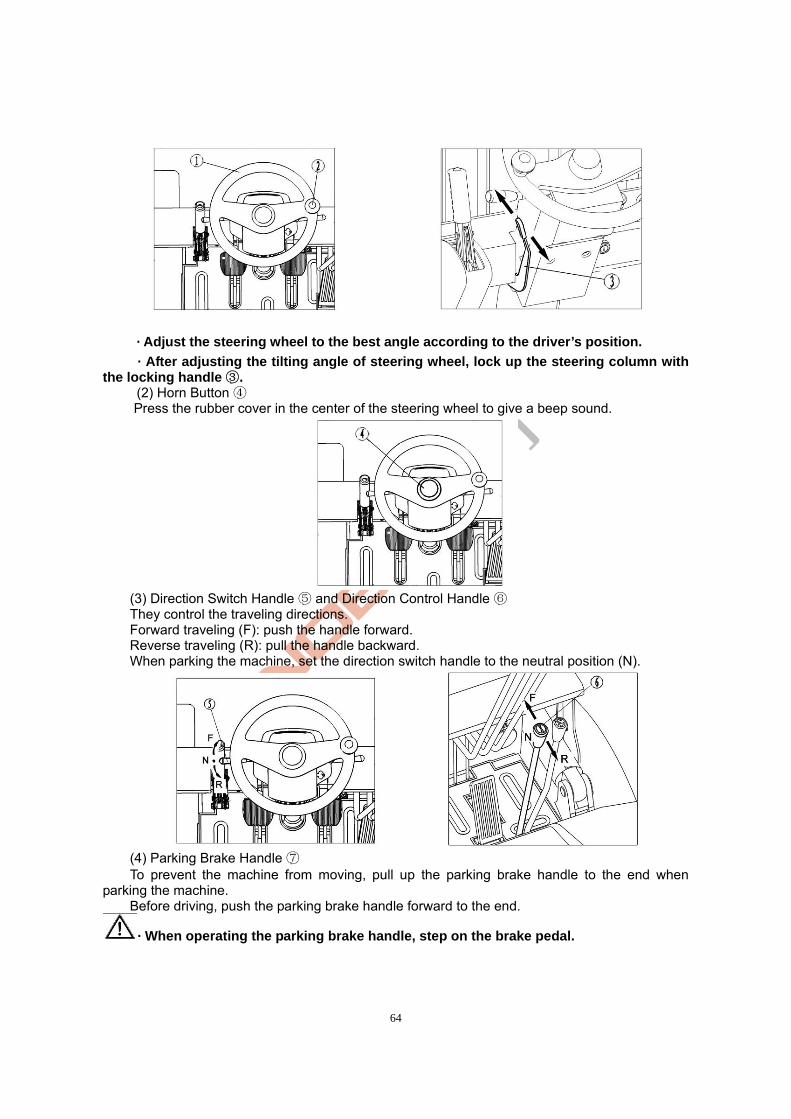
64
· Adjust the steering wheel to the best angle according to the driver’s position.
· After adjusting the tilting angle of steering wheel, lock up the steering column with the locking handle .③
(2) Horn Button ④ Press the rubber cover in the center of the steering wheel to give a beep sound.
(3) Direction Switch Handle ⑤ and Direction Control Handle ⑥ They control the traveling directions. Forward traveling (F): push the handle forward. Reverse traveling (R): pull the handle backward. When parking the machine, set the direction switch handle to the neutral position (N).
(4) Parking Brake Handle ⑦ To prevent the machine from moving, pull up the parking brake handle to the end when
parking the machine. Before driving, push the parking brake handle forward to the end.
· When operating the parking brake handle, step on the brake pedal.

65
(5) Clutch (Inching) Pedal , Brake Pedal and Throttle Pedal ⑧ ⑨ ⑩
· Do not step on the throttle pedal forcibly to avoid sudden startup or acceleration. · When stepping on the brake pedal, make sure the throttle pedal is not pressed down
any more. The pedals shown in the following figure are clutch (inching) pedal , brake pedal⑧ ⑨ and
throttle pedal from left to right ⑩. Step on the throttle pedal slowly. The traveling speed of machine is determined by the
pressing travel of throttle pedal.
(6) Lifting Handle ⑪ Pull the lifting handle backward to lift the fork; push the lifting handle forward to lower the fork.
The lifting/lowering speed depends on the tilting angle of handle. The larger the angle is, the larger the speed will be.
· If you turn on the key switch and push/pull the lifting handle at the same time, the lifting operation will be disabled.
· Do not suddenly lower or stop lowering the fork.
(7) Tilting Handle ⑫ Pull the tilting handle backward to tilt the mast
backward; push the tilting handle forward to tilt the mast forward. The forward/backward tilting speed depends on the tilting angle of handle. The larger the angle is, the larger the speed will be.
· If you turn on the key switch and push/pull the tilting handle at the same time, the tilting operation will be disabled.
4. Machine Body

66
(1) Seat With the adjusting handle, you can adjust the seat to a proper position suitable for you. Pull the handle up to relieve the seat fixation. After seat adjustment, slightly move the seat
forward and backward to make sure it is firmly fixed. Adjusting range of seat:120mm (forward/backward). On the dry cement floor, the vertical
acceleration of seat acting on the driver body is 2.130m/s2-2.237m/s and the comprehensive acceleration is 2.252m/s-2.356m/s.
(2) Overhead Guard
· The overhead guard prevents against material dropping from overhead. It is an important part to protect the operator. The opening at one end of the overhead guard is more than 150mm. If the material to be loaded/unloaded is smaller than 150×150mm, take other protective measures to prevent against accident caused by heavy materials dropping down. The loose installation and refitting after disassembly or modification are very dangerous, which may result in serious accidents.
(3) Backrest
· The backrest is an important safety part used to prevent the materials loaded on the fork from dropping on the operator. The loose installation and refitting after disassembly or modification are very dangerous.
(4) Traction Pin The traction pin is only used when:
· The machine can not be driven any more (e.g., the tyre is in the side ditch, etc.);
· The machine is to be loaded on or unloaded from the transportation truck.
· Never use the traction pin for traction work. (5) Fork Dowel Pin The fork dowel pin is used to fix the fork at a certain position.
To adjust the distance between the fork teeth, pull the dowel pin up, turn it for 1/4 circle and adjust the fork to the desired position. Adjust the fork distance according to the materials to be loaded/unloaded.

67
· According to the principle that the center of gravity of materials should be in consistent with the center of the machine, the fork distance should be adjusted to be equal at both sides. After adjustment, firmly fix the fork with the fork dowel pin.
· To adjust the fork distance, lean against the backrest, stand up, and push the fork with your feet. Never adjust the fork by hand.
(6) Footboard and Handrail A footboard is set at the left of the machine body. A handrail is set on the left front supporting rod of overhead guard. Use the footboard and handrail to get on/off the machine.
(7) Lamps The headlamp and front combination lamp (turn signal
lamp, parking lamp and width lamp) are set at the front of the machine. The warning lamp and rear combination lamp (including tail lamp, turn signal lamp, braking lamp, parking lamp, reversing lamp and flasher) are set at the rear of the machine.
· Check the working condition of all lamps. In case of burnt-out bulb or damaged/dirty lampshade, replace or repair it at once.
(8) Rear-view Mirror The rear-view mirror is mounted at the right of the front cross beam of overhead guard.
· Keep the surface of rear-view mirror clean. · Adjust the rear-view mirror to a position where
you can see the back clearly. (9) Fire Prevention and Fire Fighting ① Do not use open fire to check the fuel consumption
or leakage. Do not use open fire to check the electrolyte level and coolant level.
② Never smoke or carry open fire during battery overhaul, oil handling or fuel system maintenance. It may lead to fire or explosion.
③ Stop the engine before filling fuel into the fuel tank. In case of unexpected fire, take measures to put it out, such as using the fire extinguisher.
④ As required by the working environment, the machine may be equipped with an ammonium phosphate powder fire extinguisher. Such fire extinguisher is applicable to the fire on ordinary solid materials, combustible fluid and gas/steam.
III. Machine Safety
Safety is your business and responsibility. This section mainly describes the basic safety regulations and cautions in the general operation of standard forklift truck. However, it is also applicable to the forklift truck with special specifications, mast or other attachments.
1. Working Place and Environment
(1) Ground The machine should work on a flat and solid ground or pavement. Besides, the working place
should be well ventilated. The working performance of the machine depends on the specific condition of the ground.
The traveling speed should be proper. Take care when driving the machine on a slope or rough pavement, as it may speed up the wear in tyre and increase the noise.
(2) Working Environment
Handrail
Footboard
Headlamp
Front combination lamp
Warning lamp
Rear-view mirror
Rear combination lamp

68
The ambient temperature for the working environment should be -30°C~50°C and the ambient humidity should be no more than 80%.
(3) Weather Conduct a safety assessment before driving the machine in rainy, foggy, snowy or windy days.
In such weather, try not to carry out operation outdoors. If you have to do so, take care when driving and operating the machine.
2. Safety Rules
No traveling on the highway! Wear working uniform properly before driving!
Keep alert: injury, help! Read the Operation Manual carefully before
driving!
Only trained driver with a driving license may operate the machine!
Driving license
Helmet
Goggles Earcaps

69
No fitting or disassembly of parts without permission! Read the Operation Manual carefully before driving!
Stop the engine before maintenance! Obey the traffic rules!
Take care to avoid scald by coolant! Exhausted gas may make you suffocative in
closed room!
Check the machine before use! Do not move the overhead guard!

70
Keep the cab clean! Do not operate the unsafe machine!
The driver should be healthy! Make sure your machine is safe!
Operate the machine within allowable range! Do not operate the damaged machine!
Hold the handrail when geting on the machine! Start the machine correctly!

71
Properly adjust the seat before driving! Make sure your machine is under safe working
condition!
Fasten the seat belt! Pay attention to the height for working area!
Use the lighting lamp in dark area! Do not leave your arms and body outside the
overhead guard!
Do not drive the machine on soft or unsorted pavement! Keep your body under the overhead guard!

72
No eccentric loading! Keep the fork away from the materials ahead
during loading!
Check the position of fork dowel pin! Take care in the working area!
No driving on smooth or slippery floor! Pay attention to the lateral stability under
non-load condition!
Take care when handling long or wide material! No ride!

73
No chasing when driving the machine! No standing on the materials!
No looking around during driving! No stunts with the machine!
Drive at reversing gear or under guidance if the material stack is too high to block your view!
Obey the traffic rules and all warning labels!
Use boards or timber blocks to handle small-sized materials!
Slow down and sound the horn when driving at the corner!

74
Forward gear for uphill driving and reversing gear for downhill driving of loaded machine!
Pay attention to the slope gradient and lifting height during uphill driving!
Reversing gear for uphill driving and forward gear for downhill driving of non-loaded machine!
Pay attention to the brake when starting the machine on a slope gradient!
No steering on a slope! or article on Sound the horn when there is people
Take care to avoid knocking down people or article during steering!
Keep away from the machine under operation!

75
Steering at high speed may lead to tilting due to instability
No passing through the working area!
Pay attention to the change in rated lifting capacity! Pay attention to the surrounding during driving!
Use the fork correctly for loading! Slow down during loading!
No driving when there is people in front of the machine! Do not walk or stand under the lifted fork!

76
The material stack should be lower than the backrest! Bind up the unfixable materials before loading!
Do not move the unloaded materials! Do not carry the damaged package on shoulder!
No misuse of fork! Carefully transport the materials on the truck!
No ride! No misuse of fork truck!

77
Do not stretch out from the machine during driving! No sudden acceleration or deceleration!
Use safety equipment to lift people for work at heights! No over-loading!
No lifting when it is too windy! No working in explosive environment!
Park the damaged machine at specified area! Park the machine not to be used at specified area!

78
When the machine is not to be used: — Apply the brake.
— Set the direction switch at neutral position. — Lower the fork on the ground.
— Tilt the mast forward. — Take off the key.
3. Handling of Machine
No lifting from the top! No lifting from the frame!
Correctly lift the machine!
Lifting of Machine
No parking on a slope!

79
· Firmly fix the steel wire ropes on the lifting holes at both ends of the external mast cross beam and the lifting hook of counterweight. Use a lifting device to lift the machine. The steel wire rope connecting to the counterweight should pass through the opening of overhead guard and the overhead guard should not be stressed.
· When lifting the machine, do not let the steel wire rope wind up with the overhead guard.
· The steel wire rope and lifting device should be rigid enough to safely support the heavy machine.
· Do not lift the machine from the cab frame (the overhead guard). · Do not stand under the machine when lifting it. · Drain off the fuel in fuel tank.
4. Avoidance of Tilting and Self-protection Measures
Do not tilt forward to lift the fork for loading! Otherwise, tilting may occur!
No inclined material lifting!
No eccentric loading! No driving on smooth pavement!

80
No loading/unloading when the machine is not on flat ground! No driving over obstacles such as ditch, mound and railway which may easily lead to tilting!
Keep 15cm~20cm between the fork and ground during traveling! No fast and big turning under loaded/non-loaded condition!
Small turning when the fork is lifted under loaded condition! Fasten the safety belt!
Do not jump from the machine in case of tilting! Wear helmet when driving the machine!

81
In case of tilting, it is safer to stay on the machine with the safety belt fastened than to jump from the machine. If the machine starts to tilt over:
1. Step on the floor and hold on the steering wheel. 2. Do not jump from the machine. 3. Lean your body to the reverse direction of tilting. 4. Lean forward.
5. Notes on Safety in Maintenance
(1) Maintenance Place
· The maintenance place should be the specified one with sufficient equipment and safety protection facilities for the service personnel.
· The place should be of flat ground. · The place should be well ventilated. · The place should be equipped with fire extinguishing apparatus.
(2) Precautions Before Maintenance
· No smoking. · Wear all protective articles (helmet, protective shoes, goggles, gloves and boots)
and the proper uniform. · Wipe off the oil flowing out in time. · Before filling oil, use a brush or a piece of cloth to clear the dirty oil or dust on the
connector. · Unless it is needed, turn off the key switch.
· Keep the fork lowered on the ground during maintenance. · Clean the electrical elements with compressed air.
(3) Precautions in Maintenance
· Do not leave your feet under the fork. Otherwise, you may be tripped over by the fork. · When the fork is lifted, in case the fork and mast may drop down suddenly, pad up

82
the internal mast with blocks or something else. · Watch out when opening and closing the front back plate and engine hood. There is danger of finger squeezing. · When the work is not finished at this time, leave a mark for the next work. · Use the proper tools. Do not use temporary tools. · As the pressure in hydraulic oil circuit is very high, do not carry out maintenance before the pressure in oil circuit is reduced. · Go and see the doctor immediately after high-voltage electric shock. · Never use the mast assembly as a ladder.
· Never leave your hands, feet or body between the frame and mast assembly.
(4) Inspection and Replacement of Tyre
· Only professional personnel can remove and fit the tyre. · Only professional personnel can handle the high-pressure air. · Wear goggles when using compressed air.
· When removing the tyre, do not dismount the bolt and nut at the rim connection. The high-pressure gas in the tyre may lead to danger if the bolt, nut and rim get loose.
· Before removing the bolt and nut at the rim connection, discharge the high-pressure gas in the tyre in a special device.
(5) Use of Jack (In Replacement of Tyre)
· When using a jack to jack up the machine, do not lie below the machine. ·When using a jack to jack up the machine, make sure there is no one or loads on the
machine. · When the wheels are off ground, stop jacking and set blocks under the machine to prevent against machine falling.
· Before using a jack to jack up the machine, take measures to prevent the machine from slipping.
(6) Discharging Requirements (Electrolyte, Oil)
· The waste parts on the machine (such as plastic parts, electrical elements) and the waste fluid (such as hydraulic oil, brake fluid) should be recycled according to local regulations.
6. Labels
The labels affixed on the machine are used to illustrate the operating method and precautions. They are not only good for you, but also good for the machine. If the label falls off, affix it on the machine again.

83
Left Safety Label Right Safety Label Lubrication Diagram
Oil Filling Label Lifting Label “No Lifting” Label
Hydraulic Oil Label Fuel Label
Machine Use Guide Nameplate

84
Load Curve Label Machine Lifting Label
“No Climbing” Label Fan Alarm Label
Tyre Pressure Label “Squeezing Alarm” Label
Hand Brake Label Tyre Disassembling Label

85
Chapter IV Regular Inspection and Maintenance A thorough inspection beforehand may help to avoid the occurrence of faults and shortened service life. The intervals given in the maintenance procedures are basing on 8 hours of operation a day and 200 hours of operation a month. To ensure the safety of operation, you should carry out maintenance according to the maintenance procedures. The daily maintenance may be done by the machine driver. Other inspection and maintenance should be done by professional maintenance personnel.
I. Inspection Before Use
To ensure the safety and keep the good working condition, it is a duty to carry out a thorough inspection before operation. In case of any problem, please contact our sales department.
· A minor mistake may lead to a serious accident. Do not operate or move the machine before the repair is finished or the inspection is to be started.
· Check the machine on a platform. · Before the inspection on electrical system, turn off the key switch.
· The improper treatment of waste oil (such as draining the oil into sewage or soil or burning the oil) may lead to pollution in water, soil and air. It is forbidden by law.
1. Inspection Points and Task
No. Inspection Point Task
1 Brake pedal Travel and braking force of foot pedal
2 Brake oil Oil volume and cleanliness Brake system
3 Parking brake Travel and braking force of parking brake
4 Control of steering wheelTightness, rotation and forward/backward movement Steering
system 5
Operation of hydraulic steering
Operation of all parts
6 Function Function, cracking and lubrication
7 Oil pipe Oil leakage at oil pipe
8 Hydraulic oil Oil volume
Hydraulic system and mast
9 Lifting chain Consistent tightness of chains at both sides
10 Tyre Air pressure, abnormal damage Wheel
11 Hub nut Tightness
Storage battery
12 Charging Battery capacity display, specific gravity and tight plug connection
Lamp, horn and switch
13
Headlamp, tail lamp, reversing lamp, turn lamp, horn and emergency stop switch
Lamp on/off condition, horn sounding condition, switch working condition
Detector and display lamps
14 Function Indication of “normal detection status” when key switch is turned on
15 Overhead guard, backrest
Tightness of bolt and nut
16 Nameplate and label Integrity Others
16 Other parts Abnormal condition
2. Inspection Procedures

86
(1) Inspection of Foot Brake Pedal ⑧ Check the braking condition. Make sure when the brake pedal is completely pressed down, the travel of brake pedal from the bottom plate is over 50mm. The braking distance of non-loaded machine is about 2.5m.
(2) Inspection of Brake Oil
· Open the brake oil cup cover to check the brake oil level and other condition.
(3) Inspection of Parking Brake Handle Push the parking brake handle forward and check: · If the pulling stroke is proper; · The braking force; · If there is damage in parts; · If the pulling force (standard: 17-22kg) is suitable for the operator. It can be adjusted by the screw on the top of the handle.
(4) Inspection of Rotation of Steering Wheel Slightly turn the steering wheel clockwise and anti-clockwise to check for rebounding. A
rebounding travel of 50-100mm is acceptable. The travel in front and rear directions are about 7° respectively. If the steering wheel meets the above requirements, it is under normal condition.
Brake oil cup cover
Brake oil cup

87
(5) Inspection of Power Steering Function Turn the steering wheel clockwise and anti-clockwise to check the power steering function.
(6) Inspection of Hydraulic System and Mast Check if the lifting and forward/backward tilting functions are normal and smooth.
(7) Inspection of Oil Pipe Check the lifting cylinder, dump ram and all pipelines for oil leakage. (8) Inspection of Hydraulic Oil
Lower the fork on the ground and use an oil level indicator to check the hydraulic oil level. When the oil level is between the “H” and “L” marks, the oil level is acceptable.
(9) Inspection of Lifting Chain Lift the fork 200-300mm off ground and make sure the chains at both sides are equally tightened. Check if the cap bar finger is at the middle. If the chain is not equally tightened, adjust the chain connector.
· After adjustment, tighten the double-headed nut. (10) Inspection of Tyre (Pneumatic Tyre) Remove the valve cap and use a tyre gauge to measure the
tyre pressure. After that, make sure there is not air leakage at the valve and then fit the valve cap.
· The tyre pressure of a forklift truck is higher than that of other cars. However, the tyre pressure should not exceed the specified value.
Machine Model Wheel Tyre Model Tyre Pressure
Front Wheel 7.00-12-12PR 0.86 FD20/25(T)
Rear Wheel 6.00-9-10PR 0.86
Front Wheel 28×9-15-12PR 0.83 FD30/35(T)
Rear Wheel 6.50-10-10PR 0.79
Rebound travel
Lifting chain
Chain connector
Double-headed nut
Split pin

88
Inspection of Tyre (Solid Tyre) Check the tyre and its side faces for damage or crack. Check the rim and retainer for
deformation or damage. (11) Inspection of Hub Nut
· It is very dangerous if the hub nuts get loose, as the wheel may shed off and make the machine tilt over. Check the hub nuts for looseness. Even if only one hub net gets loose, it is also very dangerous. Thus, tighten the hub nuts to the specified torque.
Tightening Torque of Hub Nut (N.m):
(12) Inspection of Headlamp, Turn Signal Lamp and Horn Check if these lamps work normally. Check if the horn works normally (the horn should give a
sound after pressing the horn button). Check if the emergency stop switch works normally.
(13) Inspection of Instrument Panel Normally, the instrument panel will indicate the information about the machine in few seconds
after the key switch is turned on and the engine is started. Refer to 4.5 Instrument Assembly (Page 38).
(14) Inspection of Overhead Guard and Backrest Check the bolts and nuts for looseness. (15) Others Check other parts for abnormity. Check the integrity of machine labels.
· Except the inspection of lamps and their operation, turn off the key switch before the inspection on electrical system.
II. Inspection After Operation
After the operation, remove the dirts on the machine and do the following work: (1) Check all parts for damage or leakage. (2) Check for deformation, distortion, damage or breakage. (3) Fill grease as needed. (4) Lift the fork to the max. lifting height for several times. (If the fork is not used in the
operation, lifting the fork to the max. lifting height may keep the oil flowing through the whole oil circuit of cylinder to prevent against rust.)
Machine Model Wheel Tyre ModelTightening
Torque Front wheel 7.00-12-12PR 470-550
FD20/25(T) Rear wheel 6.00-9-10PR 105-130
Front wheel 28×9-15-12PR 470-550 FD30/35(T)
Rear wheel 6.50-10-10PR 105-130
L Left turn signal
lamp on
N Neutral position
R Right turn signal
lamp on
Horn button
89
(5) Replace the abnormal parts causing faults in the operation.
· A minor mistake may lead to a serious accident. Do not operate or move the machine before the repair is finished or the inspection is to be started.
III. Cleaning
· Park the machine at the specified place. · Pull up the parking brake handle. · Press down the emergency stop switch. · Turn off the key switch and take off the key.
1. Exterior Surface Cleaning
Do not clean the machine with flammable fluid. Take safety measures to prevent against short circuit.
· Clean the machine with clean water and soluble detergent. · Carefully clean the surrounding of oil filler and lubricating nipple. Lubricate the machine in time if you clean it frequently.
2. Chain Cleaning
Do not clean the chain with chemical detergent, acid liquid or other corrosive liquid. · Put a container under the mast. · Clean the chain with petrochemical derivative such as gasoline. · Do not use any additives when cleaning the chain with a steam nozzle. · After cleaning, wipe up the chain axis pin and the chain.
3. Electrical System Cleaning
Do not clean the pump control parts and all connectors with water, otherwise, damage in electrical system may occur.
Clean the electrical system with a non-metal brush or a blower of low power according to the manufacturer’s instructions. Do not move the protective cover.
4. Operation After Cleaning
· Completely wipe off the water on the machine (e.g., using compressed air). · Start the machine according to the relevant procedures.
If the motor gets damp, get rid of the moist at first. Otherwise, short circuit may occur.
The moist may affect the braking performance. The short and repeat braking application may make the brake dry.
IV. Maintenance
· The regular inspection and maintenance may help to keep the machine in a good condition. · Use original Noblelift parts. · Do not use the oil of different grade in oil change or oil filling. · Do not randomly dump or discard the oil and storage battery after replacement. Handle them
according to the local environmental regulations. · Make up a comprehensive maintenance plan. · Keep a complete record after each maintenance operation. · The repair work should not be done by untrained personnel.

90
· No fire. · Turn off the key switch before maintenance work (except some inspections for
troubleshooting). · Clean the electrical parts with compressed air instead of water. · Never leave your hands, feet or body between the mast and instrument stand.
1. Routine Maintenance
The daily technical service on machine, called as the routine maintenance, includes: (1) Clean the interior and exterior of machine body and the chassis, especially: the fork arm
carrier, mast carriage and air filter. (2) Check the tightness of all parts, especially: the fork arm carrier, lifting chain, front/rear
wheel bolt, brake, steering cylinder connecting bolt, engine and accessories. (3) Check the reliability and flexibility of lamps, instrument, horn, hand brake, foot brake and
steering system. (4) Check the oil pipe connectors, water pipe connectors, fuel tank, working oil tank, brake
master cylinder, multi-way change valve, lifting cylinder, water tank, water pump, engine oil pan, gearbox, drive axle, full hydraulic steering gear, steering cylinder and exhaust pipe for leakage.
(5) Check for shortage of fuel, working oil, lubricating oil, cooling water and tyre pressure. (6) Discharge the sediments in the engine oil filter.
2. Class I Maintenance
Carry out the class I maintenance after 100 hours of machine operation. It includes: (1) The maintenance tasks in routine maintenance. (2) Maintain the engine according to the technical requirements in Engine Use Guide every
125 hours of machine operation or equivalent work. (3) Check the sealing effect and working reliability of hydraulic system. (4) Check the working reliability of all parts of the steering system and brake system. (5) Check the gear shifting operation of gearbox. (6) Check the filtration screen at the oil filler of fuel tank for blockage or damage. If any, clean
or replace the filtration screen. (7) After re-fitting the parts dismounted during maintenance, carry out a road test on the
machine, including: Check the braking performance, steering performance, off tracking, zigzag driving as well as
the reliability of hand/foot brake. Check for abnormal noise at the engine under acceleration, deceleration, heavily loaded or
non-loaded working conditions. Check the lifting and lowering of fork arm carrier. After the road test for a certain distance, check the brake drum, gearbox and engine working
oil tank for overheating. (8) Check the specific gravity and level of electrolyte in storage battery. The electrolyte level
should be 10mm~15mm higher than the polar plate. If the level is low, fill distilled water in time. Never fill concentrated sulfuric acid or electrolyte (dilute sulfuric acid). Check if the vent hole on the storage battery cover is unblocked.
(9) Check the reliability of the connection between drive axle, steering axle and frame. (10) Check the lifting chain for inclination.
3. Class II Maintenance
Carry out the class II maintenance after 500 hours of machine operation. It includes: (1) The maintenance tasks in class I maintenance. (2) Maintain the engine according to the technical requirements in Engine Use Guide every
250 hours of machine operation or equivalent work. (3) Remove the fuel tank cover and clean the filtration screen. (4) Change the lubricating oil in gearbox and drive axle. Clean the hydraulic (working) oil tank
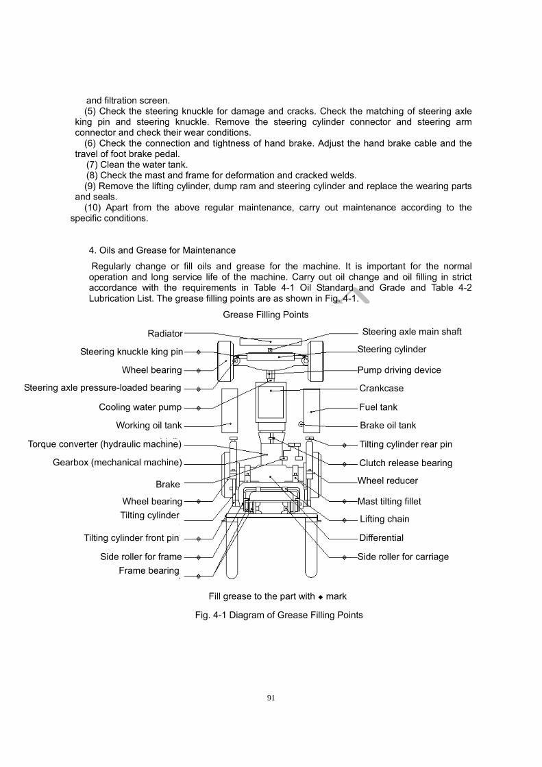
91
and filtration screen. (5) Check the steering knuckle for damage and cracks. Check the matching of steering axle
king pin and steering knuckle. Remove the steering cylinder connector and steering arm connector and check their wear conditions.
(6) Check the connection and tightness of hand brake. Adjust the hand brake cable and the travel of foot brake pedal.
(7) Clean the water tank. (8) Check the mast and frame for deformation and cracked welds. (9) Remove the lifting cylinder, dump ram and steering cylinder and replace the wearing parts
and seals. (10) Apart from the above regular maintenance, carry out maintenance according to the
specific conditions.
4. Oils and Grease for Maintenance
Regularly change or fill oils and grease for the machine. It is important for the normal operation and long service life of the machine. Carry out oil change and oil filling in strict accordance with the requirements in Table 4-1 Oil Standard and Grade and Table 4-2 Lubrication List. The grease filling points are as shown in Fig. 4-1.
Fig. 4-1 Diagram of Grease Filling Points
Grease Filling Points
Fill grease to the part with ◆ mark
Steering axle main shaft
Steering cylinder
Pump driving device
Crankcase
Fuel tank
Brake oil tank
Tilting cylinder rear pin
Clutch release bearing
Wheel reducer
Mast tilting fillet
Lifting chain
Differential
Side roller for carriage
Frame bearing
Tilting cylinder
Tilting cylinder front pin
Side roller for frame
Radiator
Steering knuckle king pin
Wheel bearing
Steering axle pressure-loaded bearing
Cooling water pump
Working oil tank
Torque converter (hydraulic machine)
Gearbox (mechanical machine)
Brake
Wheel bearing

92
Table 4-1 Oil Standard and Grade No. Standard Number Standard Name Oil Grade
1 GB11122-1997 Diesel engine oil (CD grade) 10W/40 (in winter) 15W/40 (in summer)
2 GB11118.1-1994 Mineral or synthetic hydrocarbon hydraulic oil
L-HM32
3 GB/T13895-1992 Heavy-duty gear oil (GL-5) 85W/90 4 GB12981-2003 Motor vehicle brake fluid HZY3 5 SH/T0039-1990(98) Industrial Vaseline
6 GB491-1987 Calcium-based grease ZG-2 (in winter) ZG-3 (in summer)
7 SH/T0368-1992 Calcium-sodium based grease ZGN-1
8 Q/SY018.4403-1986 Hydraulic transmission oil 6# hydraulic transmission oil
9 GB252-2000 Light diesel oil 0# (in summer), -10#--35# (in winter)
10 GB11121-1995 Gasoline engine oil 30#--40# Note: (1) The oil added with extended life coolant shall not be drained off even the
temperature is low. Just fill oil according to the original proportion. Change the oil every 2-4 years. (2) As for the oil without extended life coolant, fill oil by a proportion of 1:1 as needed.
Drain off the cooling water in winter. As for the new machine or machine after long-term storage, in the first two weeks of
operation, lubricate the bearing. Before filling grease, fill enough new grease to discharge the old grease. Carry out such operation for at least 2 times. Besides, pay attention to the following points:
(1) Before lubrication, remove the dirts on the oil tank cover, oil plug or oil cup. Otherwise, dirt may enter into the said parts.
(2) When filling grease with a grease gun, fill the grease to the joints of all parts till there is grease flowing out. After that, wipe off the grease flowing out.
(3) When the machine is to be stored for a long time, apply anti-rust grease on the exposed surface.
(4) Change the grease accordingly in winter or summer.
Table 4-2 Lubrication List
Interval No. Part Places Oil/Grease
1d 100h 500h Remarks
1 Drive axle Gear oil 85W/90 ◇
2 Gearbox 30# or 40# gasoline oil ◇
3 Working oil tank
Hydraulic oil L-HM32 Change every 1200-1500h
4 Brake master cylinder
Alcohol-type motor vehicle brake fluid
◇
5 Storage battery polar plate
2 Industrial Vaseline ☆
6 Mast carriage ZG2 or ZG3 calcium-based grease
☆
7 Driving wheel hub bearing
2 ZG2 or ZG3 calcium-based grease
◇
8 Turning wheel hub bearing
2 ZG2 or ZG3 calcium-based grease
9 Steering axle bearing seat
2 ZG2 or ZG3 calcium-based grease
☆

93
10 Steering knuckle king pin
4 ZG2 or ZG3 calcium-based grease
O ☆
11 Steering pull rod ball pin
4 ZG2 or ZG3 calcium-based grease
O ☆
12 Steering cylinder ball pin
2 ZG2 or ZG3 calcium-based grease
O ☆
13 Lifting chain ZG2 or ZG3 calcium-based grease
◇
14 Sprocket shaft 2 ZG2 or ZG3 calcium-based grease
☆
15 Connecting shaft of mast and drive axle
2 ZG2 or ZG3 calcium-based grease
☆
16 Steering gear connecting flange
1 ZG2 or ZG3 calcium-based grease
☆
17 Dump ram connecting shaft pin
4 ZG2 or ZG3 calcium-based grease
☆
18 Clutch bearing seat
1 ZG2 or ZG3 calcium-based grease
☆
19 Oil pan
Low supercharging diesel engine oil 10W/40 (in winter) 15W/40 (in summer) or SHELL diesel engine oil
O ◇
Change oil after50 hours of new diesel operation
20 Water pump shaft
1 ZG2 or ZG3 calcium-based grease
☆
21 Generator roller bearing
2 ZG2 or ZG3 calcium-based grease
◇
Note: (1) d - day, h - hour; (2) “O”-inspection, “ ”☆ -oil filling, “ ”◇ -oil change.
5. Maintenance List (Table 4-3~Table 4-11)
The maintenance lists are basing on the general working conditions. If the machine works under rough working conditions, the intervals for preventive maintenance specified in the lists should be shortened. (The shaded boxes in the lists indicate the replacement of parts or change of oil/grease/fluid). The 8h overhaul refers to the daily overhaul. The 200h inspection refers to the 200h overhaul or monthly overhaul. The tools used for the specific overhaul is given in the brace.
Table 4-3 Engine
Part Task 8h 50h 200h 600h 1200h
Engine operation check ● ● ● ● ●
Engine working noise check ● ● ● ● ●
Exhaust gas color check ● ● ● ● ●
Air filter core check/replacement ● ● ● ● ●
Engine
Valve clearance check (gauge) ● ●

94
Cylinder compression check (compressometer)
● ● ●
Cylinder head bolt check ● ● ●
Main fixing bolts check ● ● ● ● ●
Engine oil leakage check ● ● ● ● ●
Engine oil level and cleanliness check ● ● ● ● ●
Engine oil change ● ● ●
Engine oil filter core cleaning ● ● ● ●
Lubrication system
Engine oil filter core replacement ● ● ●
Fuel leakage check ● ● ● ● ●
Fuel filter blockage check ●
Fuel filter core replacement ● ● ●
Injection nozzle pressure and condition check (injection nozzle test)
● ● ●
Fuel injection pump filter cleaning ● ● ●
Fuel tank water drain ● ● ●
Fuel system
Fuel level check ● ● ● ● ●
Coolant level check ● ● ● ● ●
Water leakage check ● ● ● ● ●
Aged upper/lower water pipe check ● ● ● ●
Water tank cover seals and spring check ● ● ● ●
Coolant change (extended life coolant change once every 2 years)
● ●
Fan belt tension check ● ● ● ●
Cooling system
Water pump grease filling ● ● ●
Table 4-4 Power Transmission System
Part Task 8h 50h 200h 600h 1200h
Free travel and distance from pedal surface to bottom plate check
● ● ● ● ●
Clutch operation check ● ● ● ● ● Friction clutch
Clutch slipping and engagement check ● ● ● ● ●
Oil leakage check ● ● ● ● ●
Oil level check and oil change ● ● ● ● ●
Hydraulic gearbox and
torque converter Shift lever operation and tightness
check ● ● ● ●

95
Control valve and clutch operation check
● ● ● ●
Inching valve operation check ● ● ● ●
Inching pedal free travel and working stroke check
● ● ● ● ●
Oil filter core replacement
Oil suction filter cleaning ● ● ● ●
Oil leakage check ● ● ● ● ●
Oil level check and regular oil change ● ● ● ● ● Front axle and
terminal reducer
Fixing bolt tightness check ● ● ● ●
Table 4-5 Wheel
Part Task 8h 50h 200h 600h 1200h
Charging pressure check (tyre gauge) ● ● ● ● ●
Damage check ● ● ● ● ●
Tyre wear check ● ● ● ● ●
Excessive wear check (depth gauge) ● ● ● ●
Tyre
Gravel or foreign substance check ● ● ● ●
Tightness check (hammer) ● ● ● ● ● Rim fixing nut
Damage check ● ● ● ● ●
Rim Rim and rim edge wear check ● ● ● ● ●
Bearing noise detection ● ● ● ● ● Wheel bearing
Cleaning and grease filling ● ● ● ●
Axle body Axle body deformation and wear check ● ●
Table 4-6 Steering System
Part Task 8h 50h 200h 600h 1200h
Steering wheel stroke check ● ● ● ● ●
Longitudinal tightness check ● ● ● ● ●
Lateral tightness check ● ● ● ● ●
Steering wheel
Steering wheel operation check ● ● ● ● ●
Oil leakage check ● ● ● ● ● Steering gear Fixing bolt tightness check ● ● ● ● ●
Connecting Connecting rod connection check ● ● ● ●

96
rod and steering arm
Deformation or excessive wear check ● ● ● ●
Steering knuckle
King pin wear check ● ● ●
Deformation or crack check ● ● Steering axle
Fixing bolt torque check ● ● ● ●
Power steering function check ● ● ● ● ●
Oil leakage check ● ● ● ● ● Power
steering Mounting parts and connector check ● ● ● ●
Table 4-7 Brake System
Part Task 8h 50h 200h 600h 1200h
Free travel check ● ● ● ● ●
Working stroke check (gauge) ● ● ● ● ●
Working efficiency check ● ● ● ● ● Brake pedal
Brake pipeline air existence check ● ● ● ● ●
Locking function and travel check ● ● ● ● ●
Braking performance check ● ● ● ● ●
Racket wear check ● ●
Hand brake handle
Racket operation check ● ● ● ● ●
Operation check ● ● ● ● ● Connecting rod, steel wire rope Wear check ● ●
Oil leakage check ● ● ● ● ● Oil pipe
Connector check ● ● ●
Oil leakage check ● ● ● ● ●
Oil level check ● ● ● ● ●
Master cylinder and wheel cylinder check ● ●
Master cylinder and wheel cylinder oil leakage or damage check
● ●
Brake master
cylinder, brake wheel
cylinder Master cylinder piston cup and one-way valve wear check
●
Clearance between brake drum and friction lining check (gauge)
● ●
Brake drum fastener tightness check ● ● ●
Friction lining wear check (slide caliper) ●
Brake shoe operation check ● ●
Brake drum, brake shoe
Fixing pin rust check ●

97
Return spring wear check (slide caliper) ●
Brake drum wear check ●
Hub disc deformation check ●
Hub disc crack check ● Brake hub
disc Fastener tightness check ● ● ●
Clearance between brake drum and friction lining check
● ●
Brake drum fastener tightness check ● ● ●
Friction lining wear check (slide caliper) ●
Central brake
Brake drum and eccentric wheel wear check
●
Table 4-8 Working System
Part Task 8h 50h 200h 600h 1200h
Fork deformation or damage check ● ● ● ● ●
Fork stop pin damage check ● ● ● Fork
Fork hook welds cracking check ● ● ●
Internal/external mast cross beam welds cracking check
● ● ●
Dump ram bearer and mast welds cracking or deformation check
● ● ●
Internal/external mast welds fault or cracking check
● ● ●
Carriage welding check ● ● ● ● ●
Roller bearing tightness check ● ● ●
Mast support bushing wear check ● ●
Lifting cylinder fixing bolt tightness check ● ● ● ● ●
Mast and carriage
Roller, roller shaft and welding parts damage or crack check
● ● ●
Chain tightness, rust and deformation check
● ● ● ● ●
Chain, guide rod and slide block lubrication
● ● ●
Chain fixing pin connection check ● ● ●
Sprocket deformation or damage check ● ● ●
Chain and sprocket
wheel
Sprocket bearer check ● ● ●
Attachment General check ● ● ● ● ●
Piston rod, piston rod head tightness and deformation check
● ● ● ● ● Cylinder
Cylinder operation check ● ● ● ● ●

98
Oil leakage check ● ● ● ● ●
Cylinder bushing wear check ● ● ●
Oil pump working noise and oil leakage check
● ● ● ● ● Oil pump
Oil pump driving gear wear check ● ●
Table 4-9 Hydraulic System
Part Task 8h 50h 200h 600h 1200h
Oil level check and oil change ● ● ● ● ●
Oil suction filter cleaning and sediment removal
● ● Working oil
tank
Oil suction filter replacement ▲
Control lever connector tightness check ● ● ● ● ● Control lever
Control lever operation check ● ● ● ● ●
Oil leakage check ● ● ● ● ●
Safety valve and tilting locking valve operation check
● ● ● ● Multi-way change valve Safety valve working pressure check (oil
pressure gauge) ●
Pipeline breakage and oil leakage check ● ● ● Pipeline and connector Oil pipe replacement (▲
Note: The mark “▲” indicates once a year or 2 years.
Table 4-10 Electrical System
Part Task 8h 50h 200h 600h 1200h
Starter Gear meshing check ● ● ●
Generator Generator operation check (ammeter) ● ● ●
Storage battery electrolyte level check ● ● ● ● Storage battery Electrolyte specific gravity check
(hydrometer) ● ● ●
Wiring harness damage check and wire clip shedding off check
● ● ● Electric circuit
Wiring connection check ● ● ●
Spark plug Spark plug clearance check and carbon deposit removal
● ●
Table 4-11 Safety Devices and Accessories
Part Task 8h 50h 200h 600h 1200h
Installation condition check ● ● ● ● ● Overhead guard and backrest Deformation or damage check ● ● ● ● ●
Turn signal lamp
Operation and installation check ● ● ● ● ●

99
Horn Operation check ● ● ● ● ●
Lighting device
Operation check ● ● ● ● ●
Reversing alarm buzzer
Operation check ● ● ● ● ●
Mirror surface cleanliness check ● ● ● ● ● Mirror reflector Back view check ● ● ● ● ●
Instrument Instrument working performance check ● ● ● ● ●
Reflector and license
lamp Surface cleanliness check ● ● ● ● ●
Seat Seat condition check and fixing bolt tightness check
● ● ●
Machine body damage check ● ● ●
Riveting condition check ● ●
Repaired parts check ● ●
Machine body
Overall condition check ● ●
Chassis lubrication check after machine cleaning
● ● ● Lubrication and working
oils Oil check for oil tank ● ● ● ● ●

100
Maintenance Records
Date Maintenance Items Remarks

101
Maintenance Records
Date Maintenance Items Remarks

102
Chapter V. Common Malfunction and Troubleshooting Some faults affecting the use of machine may inevitably appear. Please consult our after-sales service personnel according to the following tables. The service operator without maintenance qualifications should not carry out repair, disassembly and factory setting modification on the machine. Otherwise, it may result in danger.
I. Lifting System
For the specific causes and troubleshooting methods of the common malfunction in lifting system, see Table 5-1.
Table 5-1 Fault Analysis and Troubleshooting of Lifting System
Symptom Cause Remedy
Slow lifting or no lifting under full-loaded condition
Low volume efficiency due to large clearance caused by excessive wear in gear oil pump Failed overflow valve of multi-way valve Insufficient oil suction of gear oil pump Large leakage at lifting cylinder Failed safety valve spring of multi-way valve Wear in multi-way valve rod/valve body and large oil leakage Oil leakage between valve body of multi-way valve Oil leakage at hydraulic pipeline High oil temperature, diluted oil or insufficient oil flow Failed monostable diverter valve Overloading
Replace worn parts or gear oil pump. Adjust pressure of overflow valve to 16MPa. Unblock pipeline, clean oil tank filtration screen. Replace seals. Replace spring. Repair or replace it. Re-assemble it. Check and repair it. Find out the cause and change oil or stop machine for cooling (or spray water for cooling). Adjust or repair it. Keep within rated loading capacity.
Desynchronized mast tilting
Inconsistent stroke of two dump rams Unequal size of cut-off ports at connector of cylinder pipeline
Adjust cylinder stroke. Use connector with equally sized cut-off ports.
Failure to lift or tilt under non-loaded condition
Overflow ports on multi-way valve blocked
Remove blockage.
Too fast lowering of fork arm carrier/mast
Governor valve at oil inlet port not acting
Repair governor valve.
Automatic tilting/lowering of fork arm carrier/mast
Large leakage at lifting cylinder/dump ram Large leakage at multi-way valve
Replace seals or cylinder. Repair multi-way valve.
Inflexible lifting/lowering/tilting of fork arm carrier/mast
Piston rod of lifting cylinder/dump ram stuck or distorted Too much deposits in cylinder or cylinder over-sealed
Replace or repair piston rod. Clean cylinder or adjust seals.
II. Driving System
For the specific causes and troubleshooting methods of the common malfunction in driving system, see Table 5-2.
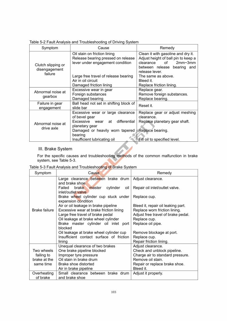
103
Table 5-2 Fault Analysis and Troubleshooting of Driving System
Symptom Cause Remedy
Clutch slipping or disengagement
failure
Oil stain on friction lining Release bearing pressed on release lever under engagement condition Large free travel of release bearing Air in oil circuit Damaged friction lining
Clean it with gasoline and dry it. Adjust height of ball pin to keep a clearance of 2mm~3mm between release bearing and release lever. The same as above. Bleed it. Replace friction lining.
Abnormal noise at gearbox
Excessive wear in gear Foreign substances Damaged bearing
Replace gear. Remove foreign substances. Replace bearing.
Failure in gear engagement
Ball head not set in shifting block of slide bar
Reset it.
Abnormal noise at drive axle
Excessive wear or large clearance of bevel gear Excessive wear at differential planetary gear Damaged or heavily worn tapered bearing Insufficient lubricating oil
Replace gear or adjust meshing clearance. Replace planetary gear shaft. Replace bearing. Fill oil to specified level.
III. Brake System
For the specific causes and troubleshooting methods of the common malfunction in brake system, see Table 5-3.
Table 5-3 Fault Analysis and Troubleshooting of Brake System
Symptom Cause Remedy
Brake failure
Large clearance between brake drum and brake shoe Failed brake master cylinder oil inlet/outlet valve Brake wheel cylinder cup stuck under expansion condition Air or oil leakage in brake pipeline Excessive wear at brake friction lining Large free travel of brake pedal Oil leakage at brake wheel cylinder Brake master cylinder oil inlet port blocked Oil leakage at brake wheel cylinder cup Insufficient contact surface of friction lining
Adjust clearance. Repair oil inlet/outlet valve. Replace cup. Bleed it, repair oil leaking part. Replace worn friction lining. Adjust free travel of brake pedal. Replace cup. Replace oil pipe. Remove blockage at port. Replace cup. Repair friction lining.
Two wheels failing to
brake at the same time
Unequal clearance of two brakes One brake pipeline blocked Improper tyre pressure Oil stain in brake drum Brake shoe distorted Air in brake pipeline
Adjust clearance. Check and unblock pipeline. Charge air to standard pressure. Remove oil stain. Repair or replace brake shoe. Bleed it.
Overheating of brake
Small clearance between brake drum and brake shoe
Adjust it properly.

104
drum Powerless brake shoe return spring Brake wheel cylinder cup stuck under expansion condition
Replace spring. Replace cup.
Failure in hand brake
Loose hand brake cable Adjust cable tension.
IV. Steering System
For the specific causes and troubleshooting methods of the common malfunction in steering system, see Table 5-4.
Table 5-4 Fault Analysis and Troubleshooting of Steering System
Symptom Cause Remedy
Oil leakage at steering
gear
Oil leakage at joint surface of steering gear (valve body, separation plate, stator and rotor) Damaged seal ring at journal Damaged seal ring at overflow valve Washer of limit bolt not flat
Replace seal ring, clean joint surface of steering gear or replace fixing bolt. Replace seal ring. Replace seal ring. Grind or replace washer.
Heavy steering
Insufficient oil supply from oil pump Air in steering system Insufficient working oils High viscosity of working oils Failed steel ball one-way valve in valve body Pressure in overflow valve lower than working pressure or overflow valve stuck by dirts Large oil leakage at steering cylinder
Adjust flow control valve. Bleed steering system and check oil suction pipe line for air leakage. Fill oil to specified level. Use specified working oils. Clean steel ball in case of seizure. Adjust pressure or clean overflow valve. Check piston seal for damage and replace seal in time.
Steering failure
Leaf spring of steering gear broken Axis pin of steering gear broken or distorted Coupling opening broken or distorted Safety valve failed Large leakage at steering cylinder Excessive wear or insufficient grease at pull rod ball pin Steering axle body distorted
Replace spring. Replace axis pin. Replace coupling. Clean safety valve and replace spring. Replace seals or cylinder. Replace worn ball pin or fill grease. Rectify it.
Light turning of steering
wheel
Efficiency dropping due to large radial/axial clearance of stator of steering gear
Replace stator and rotor.
Loose turning wheel
Damaged bearing of steering king pin Loose hub bearing Excessive wear at connector Movement of connecting ball pin
Replace bearing. Adjust bearing tightness. Adjust or replace ball pin seat. Tighten connecting ball pin.

105
Unstable steering
Air in pipeline Check oil suction pipe for oil leakage and bleed pipeline in time.
V. Hydraulic System
For the specific causes and troubleshooting methods of the common malfunction in hydraulic system, see Table 5-5.
Table 5-5 Fault Analysis and Troubleshooting of Hydraulic System
Symptom Cause Remedy
Insufficient pressure in working oil
pump
Damaged seals Oil pipe or filtration screen blocked High oil temperature or viscosity Insufficient hydraulic oil, bubble in oil or air in oil circuit Heavy wear in parts (bearing sleeve end face, oil pump gear)
Replace seals. Remove blockage and change working oil regularly. Keep a specified oil temperature or use specified oils. Fill oil or bleed oil circuit. Disassemble and check parts; repair or replace worn parts.
Large pressure
fluctuation and noise at
oil pump
Oil filter blocked Insufficient hydraulic oil Leakage at pipeline of joint surface, air in pipeline Loss of accuracy of gear
Clean oil filter. Fill hydraulic oil to specified level. Fasten each joint surface, get rid of leakage and bleed pipeline. Replace gear.
External leakage at multi-way
valve
O-rings at both ends of change valve body damaged O-rings at contact surfaces of valve body damaged Uneven joint surface of valve body
Replace O-ring. Replace O-ring. Finish joint surface.
Resetting failure of
slide valve
Return spring is distorted Part between valve body and slide valve not clean Valve is distorted due to over-tightened connecting bolt
Replace return spring. Clean valve body and slide valve. Refit bolt.
Insufficient pressure in
overflow valve
Failed spring Cone valve is worn out Loose locking nut Oil drain port blocked
Replace spring. Replace cone valve. Tighten locking nut. Remove blockage.
Mast lowering
dramatically when slide valve is at
middle position
Increased wearing clearance between valve body and slide valve Slide valve at improper position Cone valve worn out or stuck by dirts
Repair or replace slide valve. Keep slide valve at correct position.Replace cone valve or remove dirts.
VI. Electrical System
For the specific causes and troubleshooting methods of the common malfunction in electrical system, see Table 5-6.
Table 5-6 Fault Analysis and Troubleshooting of Electrical System
Symptom Cause Remedy
Starter not running or
Storage battery is short of electricity Starter power cable gets loose
Charge storage battery. Fix power cable.

106
powerless running
Poor contact between commutator and electric brush: ① erosion on commutator surface; ② electric brush is worn out Short circuit in starter Damaged electromagnetic switch or erosion on contact Heavy wear in bushing, friction between armature and pole
① Finish commutator surface with 00# abrasive paper; ② Replace electric brush.
Check and rectify short circuit. Repair or replace it. Replace bushing.
Generator not working
Fault in charging circuit ① Open circuit or short circuit ② Poor contact ③ Wrong wiring
Fault in generator ④ Poor contact between electric
brush and slip ring ⑤ Electric brush is worn out ⑥ Improper spring force ⑦ Damaged silicone elements ⑧ Damaged winding ⑨ Oil stain on slip ring
Damaged adjuster Loose fan belt
Check and rectify wiring fault. Tighten all connecting points. Check and re-connect cable cables.
Grind with 00# abrasive paper and clean it. Replace electric brush. Adjust spring force. Replace silicone elements. Repair or replace winding. Clean slip ring. Replace adjuster. Adjust belt tightness.
Horn not working
Poor contact of horn live wire Fuse blowout Open circuit at horn button
Check horn live wire and rectify it. Replace fuse. Check wire at terminal block on steering shaft for disconnection; if any, re-connect it.
Horn keep sounding
Contact between terminal block and steering shaft at steering wheel Contacts of button impossible to be separated Button spring distorted
Separate and repair them. Check button spring for distortion. Replace it.
Fuse blowout Grounding between power and all electric appliances
Check and rectify the fault, then fit a new fuse with correct specifications.
Bulb not lit up
Fuse blowout Bulb live wire disconnected or wiring shedding off Bulb damaged Switch damaged
Check and replace fuse. Check and connect wiring cables. Replace bulb. Replace switch.

107
ZheJiang Noblelift Equipment Joint Stock Co.,Ltd Tel:+86-572-6210776 6210788
Fax:+86-572-6210777 6128612
PC:313100
www:www.noblelift.com Email: [email protected]
Add:No.528.Jing Yi Road Economic Development Zone,Changxing