Embed Size (px)
Citation preview
Orvosi eszközfejlesztésben használható polimerek anyagtechnológiai vizsgálata additív
gyártástechnológiák esetén
Doktori (Ph.D.) értekezés
dr. Maróti Péter
Interdiszciplináris Orvostudományok Doktori Iskola D93
Programvezető: Prof. Dr. Sümegi Balázs
Témavezetők:
Prof. Dr. Nyitrai Miklós egyetemi tanár
Prof. Dr. Lőrinczy Dénes egyetemi tanár
Pécsi Tudományegyetem, Általános Orvostudományi Kar
Biofizikai Intézet
2019

2
Tartalomjegyzék
Rövidítések jegyzéke: ............................................................................................................. 4
1.) Bevezetés: ............................................................................................................................... 6
1.1) A 3D nyomtatás rövid története, elérhetősége ................................................................ 6
1.2) Polimerekkel és kompozitokkal dolgozó 3D nyomtatási technológiák és a hozzájuk tartozó
alapanyagok ..................................................................................................................... 8
1.2.1) FFF és FDM™ technológia ........................................................................................ 8
1.2.2) SLS technológia ..................................................................................................... 10
1.2.3) PolyJet™ technológia ........................................................................................... 11
1.2.4) 4D nyomtatás ....................................................................................................... 13
2.) Elméleti alapok ...................................................................................................................... 14
2.1) Additív gyártástechnológiai megoldások az egészségügyben .......................................... 14
2.2) A 3D nyomtatás gyakorlati aspektusai az egészségügyben .............................................. 18
2.2.1) 3D nyomtatási fájlok: ............................................................................................ 18
2.2.2) FFF/FDM™ technológia ......................................................................................... 19
2.2.3) SLS technológia ..................................................................................................... 21
2.2.4) PolyJet™ tecnhológia ............................................................................................ 22
2.3) Polimerek biokompatibilitása orvosi eszközfejlesztés esetén ......................................... 23
2.4) Vizsgálataink célja, problémafelvetés ............................................................................. 27
2.4.1) 3D nyomtatott törésrögzítések: ............................................................................. 27
2.4.2) 3D nyomtatott felső végtagi protézisek ................................................................. 28
2.4.3) Phoenix Smart Orthosis: ........................................................................................ 29
2.4.4) Fogorvosi fúrófeltét készítése: .............................................................................. 30
3.) Módszerek és alapanyagok .................................................................................................... 31
3.1) Vizsgálati Szabványok, próbatestek és minták előkészítése ............................................. 31
3.1.1) 3D nyomtatók: ...................................................................................................... 31
3.1.2) Alapanyagok: ........................................................................................................ 31
3.1.3) Nyomtatási paraméterek: ..................................................................................... 32
3.2) DTA/TG – Termoanalitikai vizsgálatok ............................................................................ 34
3.3) Statikus és dinamikus mechanikai vizsgálatok ................................................................ 35
3.4) Szerkezettani vizsgálatok SEM segítségével .................................................................... 36
3.5) CAD tervezés, modellezés .............................................................................................. 37
4.) Eredmények .......................................................................................................................... 38
4.1) DTA/TG – Termoanalitikai vizsgálatok eredményei ......................................................... 38
4.2) Statikus és dinamikus mechanikai vizsgálatok eredményei ............................................. 44
3
4.2.1) Statikus anyagtani mérések................................................................................... 44
4.2.2) Dinamikus mérések eredményei ........................................................................... 48
4.3) SEM kiértékelése ........................................................................................................... 50
5.) Megbeszélés. Az eredmények gyakorlati hasznosíthatósága ................................................... 55
5.1) 3D nyomtatással készült felső végtagi protézisek ............................................................ 55
5.2) Phoenix Smart Orthosis ................................................................................................. 57
5.3) Innovatív, 3D nyomtatással készült törésrögzítések: ....................................................... 58
5.4.) Fogorvosi fúrófeltét: ..................................................................................................... 60
6.) Eredmények összefoglalása ................................................................................................... 62
6.1) Gyakorlati felhasználhatóság: ........................................................................................ 62
6.2) Anyagtechnológiai jellemzők: ......................................................................................... 63
7.) Saját közlemények, konferenciarészvételek listája: ................................................................. 65
7.1) A dolgozat alapjául szolgáló közlemények listája ............................................................ 65
7.2) A dolgozat alapjául nem szolgáló saját közlemények és konferenciák: ............................. 66
7.2.1) Publikációk, poszterek: ......................................................................................... 66
7.2.2) Konferenciák: ....................................................................................................... 67
8.) Köszönetnyilvánítás ............................................................................................................... 69
9.) Felhasznált források .............................................................................................................. 71
4
Rövidítések jegyzéke:
ABS - Akrilnitril-Butadién-Sztirol
AM -Additive Manufacturing
AODL - Activites of Daily Living
CaCO3 – Calcium Carbonate
CAD – Computer Aided Design
CFF - Continoous Fiber Fabrication
CFRTPC -Continuous Fiber Reinforced Thermoplastic composites
CNC – Computer Numerical Control
CT- Computer Tomography
DLP - Digital Light Processing
DMLS- Direct Metal Laser Sintering
DTA – Differential Thermal Analysis
FDM™ - Fused Deposit Modelling
FFF - Fused Filament Fabrication
FTIR -Fourier-Transform Infrared Spectroscopy
HDT – Heat Deflection Temperature
IT - Information Technology
LOM - Laminated Object Manufacturing
MR – Magnetic Resonance
PA - Poliamid
PCL – Polikaprolakton
PEEK- Poli-Etil-Éter-Keton
PEGDMA - Polyethilén-Glicol-Dimethacrilate
PET-G – Polyethylene Terephthalate Glycol-Modified

5
PLA - Polilaktonsav
PMMA - Poli(Metil-Metakrilát)
PVA – Poli-Vinil-Alkohol
SEM – Scannning Eectron Microscopy
SGC - Solid-Groud Curing
SLA - Stereolithography Apparatus
SLS – Selective Laser Sintering
SMA – Shape Memory Alloy
SMP – Shape Memory Polymer
TG – Thermogravimetry
TPU - Thermoplastic Polyurethane
UV – Ultra Violet
6
1.) Bevezetés:
1.1) A 3D nyomtatás rövid története, elérhetősége
Az additív gyártástechnológiák (AM – additive manufacturing) korunk meghatározó
tudományos és ipari eszközrendszerét képezik. Egyes 3D nyomtatási eljárások már a
háztartásokba is beférkőztek [1], köszönhetően a technológia – és az ezt erősen támogató
információs technológia (IT) - rohamos fejlődésének. Mind az alapkutatási (például
anyagtechnológiai kutatások) [2], mind az alkalmazott kutatási területeken (például
orvostudományi, klinikai felhasználások [3-10], ipari, gépészeti és elektronikai [11-15]
felhasználások) egyre hangsúlyosabb szerepet kapnak. A legújabb nemzetközi tudományos
eredmények rávilágítanak, hogy az additív gyártástechnológia dinamikus fejlődés alatt áll. Az
újabb és újabb alapanyag- és gépgyártók megjelenése szükségessé teszi az eljárások
tudományos igényű vizsgálatát, ezen vizsgálatok kritikus kiértékelését, majd az eredmények
gyakorlatba történő átültetését.
Az eljárás, bár csak az elmúlt évtized folyamán kapott kiemelt hazai és nemzetközi
figyelmet, már az 1980-as években megálmodásra került. Világszerte több kutatócsoport is
olyan megoldáson dolgozott, amely lehetővé teszi, hogy nem „anyagelvonással” (mint például
CNC – computer numerical control) jönnek létre a kívánt térbeli objektumok, hanem
„anyaghozzáadással”, azaz a megalkotandó tárgy rétegről-rétegre épül fel [16], csökkentve az
anyagveszteséget, az előállítási időt, ezáltal pedig a fejlesztési, gyártási költségeket. Az első
sikeres szabadalmat Charles Hull nyújtotta be az Egyesült Államokban, 1984-ben [17], a
sztereolitográfiás eljárásra (SLA – stereolithography apparatus), mely során a kiindulási
alapanyag folyékony fotopolimer volt, melyet UV fény polimerizált. Az első kereskedelmi
forgalomban kapható gépek (3D Systems SLA-1) is ezzel az eljárással működtek (1987). Az
Egyesült Államok után, több lépésben, 1989-ig Japánban is megjelentek a szterolitográfiás 3D
7
nyomtatók (NTT Data CMET és Sony/DMEC gyártmányai), melyet a német Electro Optical
Systems (EOS) követett. Néhány évvel később, 1991-ben három újabb technológia jelent meg
a piacon, a szálhúzásos 3D nyomtatás (Fused Deposit Modelling - FDM™), az úgynevezett
„solid-groud curing” (SGC, Cubital által), mely eljárás hasonlít az SLA-hoz, illetve „laminated
object manufacturing” (LOM, Helisys által), mely során egymásra helyezett rétegekből lézerrel
vágják ki az adott struktúrát. A következő fontos mérföldkő a szelektív lézer szinterezési (SLS)
technológia megjelenése volt 1992-ben, melyet a DTM (jelenleg 3D Systems része) jegyzett
[18]. A műanyag port használó eljárás megalapozta a DMLS (Direct Metal Laser Sintering, a
németországi Fraunhofer Institute ILT által ) alapú rendszerek megjelenését [19], mely
fémport használ alapanyagként. Mindkét technológia kiemelten fontos az iparban és
egészségügyben egyaránt.
A 3D nyomatási technológia széleskörű elterjedésére a 1990-es évek közepétől volt
lehetőség, amikor több piaci szereplő a korábbiaknál jóval alacsonyabb áron kezdett
nyomtatókat gyártani és forgalmazni. Erre kiváló példa a Z. Corp Z402 nevű „inkjet”-es
modellje, vagy a Schroff Development 10.000 $ alatti papír alapú 3D nyomtatója. [18]. A 2000-
es évek közepéig a bekerülési árak folyamatosan csökkentek, és újabb technológiák jelentek
meg. A rohamos, ütemes fejlődés eredményeképpen ma már néhány 100 $-os nagyságrendű
befektetéssel lehet asztali, szálhúzásos 3D nyomtatót vásárolni (FFF-Fused Filament
Fabrication), melyek ismert képviselői például RepRap gyártmányú berendezések. Ez a
mértékű költségcsökkenés óriási hatással bírt a különböző, additív gyártástechnológiákat
alkalmazó iparágakra, különösképpen az egészségügyi, orvosi felhasználások vonatkozásában.
Köszönhetően a számos akadémiai és piaci start-up vállalatnak, nem csak az FFF, de a DLP és
SLA berendezések ára is jelentősen csökkent az elmúlt években, illetve egyéb, elsősorban ipari
technológiák elérhetősége is szélesebb körűvé vált.
8
1.2) Polimerekkel és kompozitokkal dolgozó 3D nyomtatási technológiák és a hozzájuk
tartozó alapanyagok
Számos 3D nyomtatási technológia és rengeteg alapanyag van jelen az additív
gyártástechnológiák dinamikusan fejlődő területén. Minden eljárás alapja, hogy nem
anyagelvétellel – mint például forgácsolás – vagy öntészeti eljárással, hanem anyag
hozzáadásával hozzuk létre a kívánt térformát, rétegről, rétegre. Bár a 3D nyomtatók piaca igen
széles, azonban ebben a gyártási metódusban minden technológia megegyezik. Nem csak
műanyagokkal (kompozitok, polimerek) és fémekkel, esetleg ötvözetekkel találkozhatunk,
elérhetőek beton, kerámia, sőt, étel- vagy csokoládé nyomtatók is a piacon. Az újabb
technológiák megjelenésével folyamatosan bővül a felhasználható alapanyagok palettája is,
illetve számos gyártó foglalkozik új kompozitok és ötvözetek kísérleti előállításával. Jelen
dolgozat témájának megfelelően a következőkben a polimereket használó, gyakorlatban
széleskörűen elterjedt 3D nyomtatási technológiák kerülnek ismertetésre. Ahogy más
felhasználási területeken, itt is a prototípus-, modell- és kisszériás gyártás szempontjából
előnyös aspektusok a legjelentősebbek. A soron következő fejezetekben kutatócsoportjaink
által is használt technológiák kerülnek bemutatásra.
1.2.1) FFF és FDM™ technológia
Az FFF és FDM™ (Fused Deposit Modeling) technológia – vagy más néven „szálhúzásos” 3D
nyomtatás – a leginkább elterjedt additív gyártástechnológiai eljárás. Az eltérő elnevezés
szabadalmi okokra vezethető vissza. Az FDM™ technológiát a Stratasys szabadalmaztatta,
open source megfelelője az FFF. Eltérés még a nyomtatási munkaterek kialakításában van –az
FDM™ technológia elsősorban ipari célokra lett tervezve, ezért fűtött munkatérrel és magasabb
hőmérséklet tartománnyal rendelkezik, illetve jellemzően a munkatérfogat is nagyobb,
9
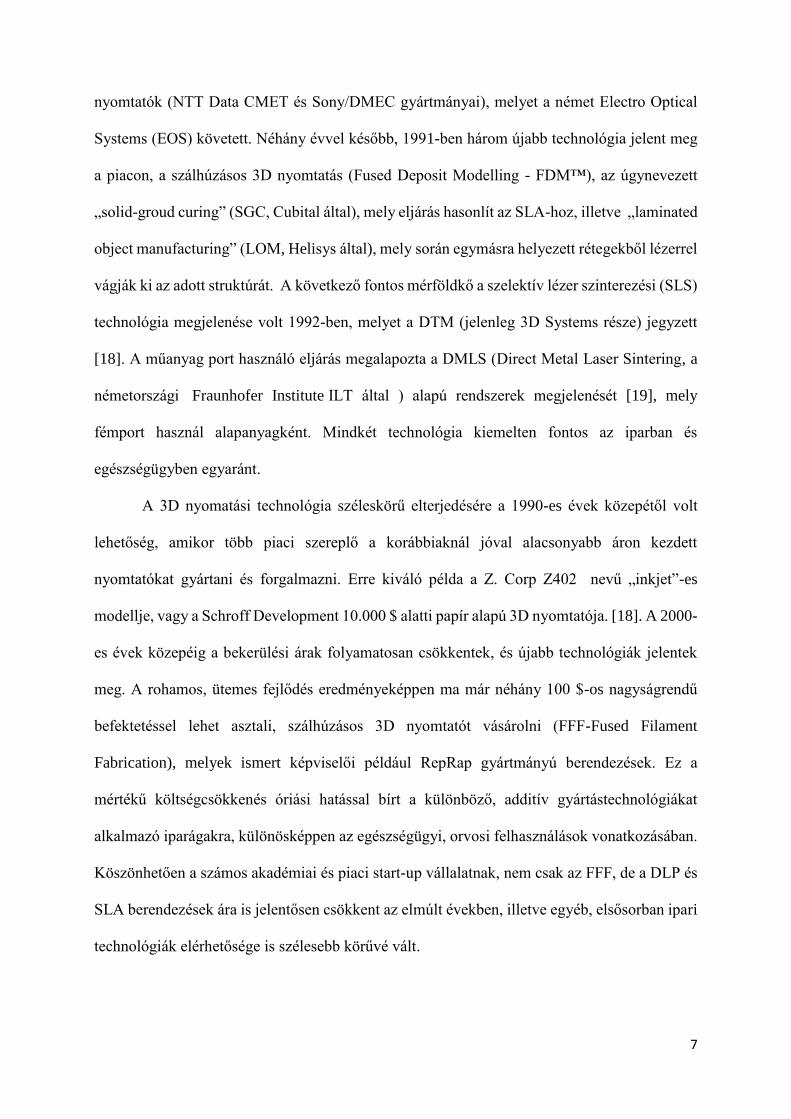
összevetve az asztali FFF gépekkel. Mindkét eljárás alapja, hogy thermoplasztikus (hőre
lágyuló) műanyag filamentet olvasztanak meg az extrúder segítségével, mely a hot-enden
keresztül távozik (1. ábra). Az FFF rendszerekben léteznek két, vagy akár több fejes nyomtatók
is, így egyszerre akár több alapanyag vagy szín is felhasználható. A kiindulási alapanyag, a
filament vagy más néven filamentum, mely átmérője jellemzően 1,75 vagy 2,90 mm. A legtöbb
esetben a nyomtató mindig egy adott X-Y síkban dolgozik, egy réteg elkészülése után a
nyomtatási tálca „lejjebb ugrik” a megadott rétegvastagságnak megfelelően, mely egyben a Z
irányú felbontást is megadja. Ez jellemzően 100-400 mikrométer közötti érték ezen eljárások
esetén. Ettől eltérő konstrukciók is léteznek, például egyes gépek esetében a tálca végez
függőleges irányú mozgást, és a nyomtatófej mozdul el Z irányban – az általános elv a modell
és fej egymáshoz képest történő, relatív irányú elmozdulása. A technológia egyik jellemzője –
és hátránya, limitációja – hogy az tálcával nem párhuzamos modell-részletek esetében
támaszanyagot nyomtat, mely mechanikusan vagy – alapanyagtól függően – oldással
eltávolítandó. Ez a poszt-processzálási (utókezelési) folyamat idő, és költségigényes.
Thermoplasztikus műanyagok széles tárháza nyomtatható: ABS, PLA, TPU, PMMA, PVA
PET-G, különböző kompozitok és keverékek (pl.: karbon és PLA vagy CaCO3 és PLA
kompozitok, de ismeretesek kő – és faporral kevert műanyagok is), illetve ipari
berendezésekben PEEK és ULTEM™ is használható. Az orvosi eszközfejlesztésben elsősorban
a PLA, PVA PMMA és PEEK alapanyagok, melyek szóba jöhetnek biokompatibilitásuk és
mechanikai tulajdonságaik alapján.
10
1. ábra: Az FFF technológia működése. Forrás: https://www.additive.blog/knowledge-base/3d-
printers/FDM™-fused-deposition-modeling-fff-pjp-lpd/. Módosítva szerző által - fordítás
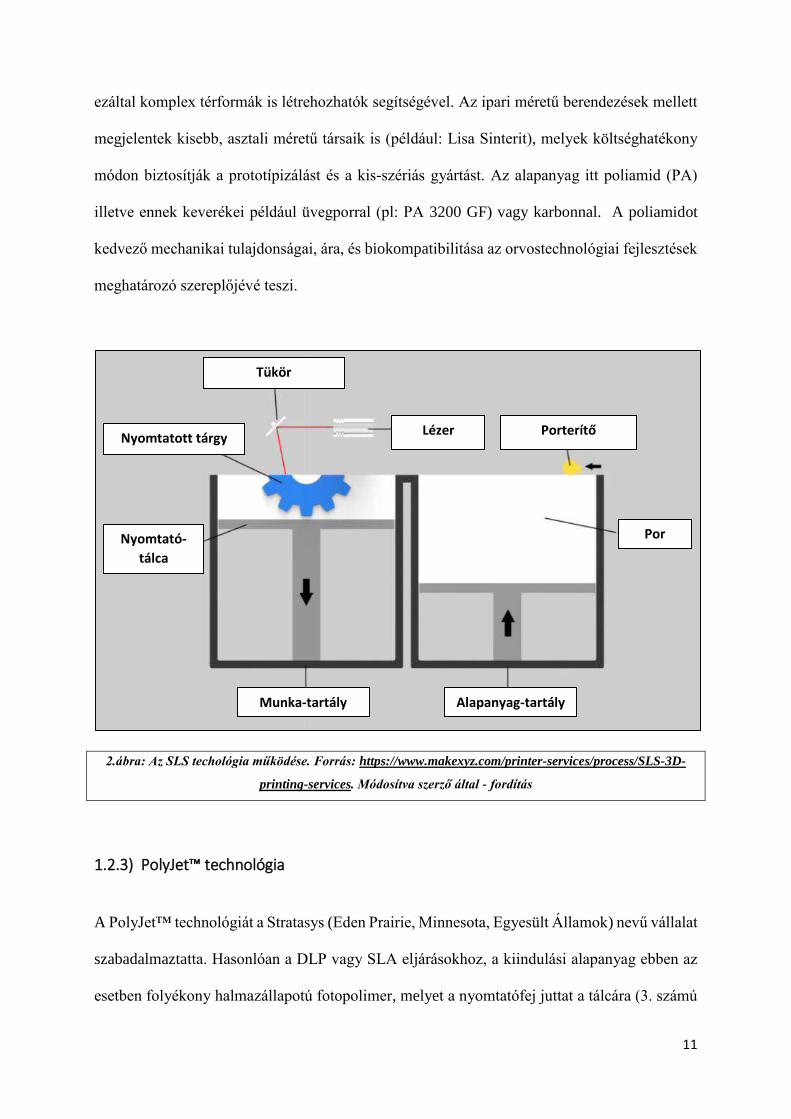
1.2.2) SLS technológia
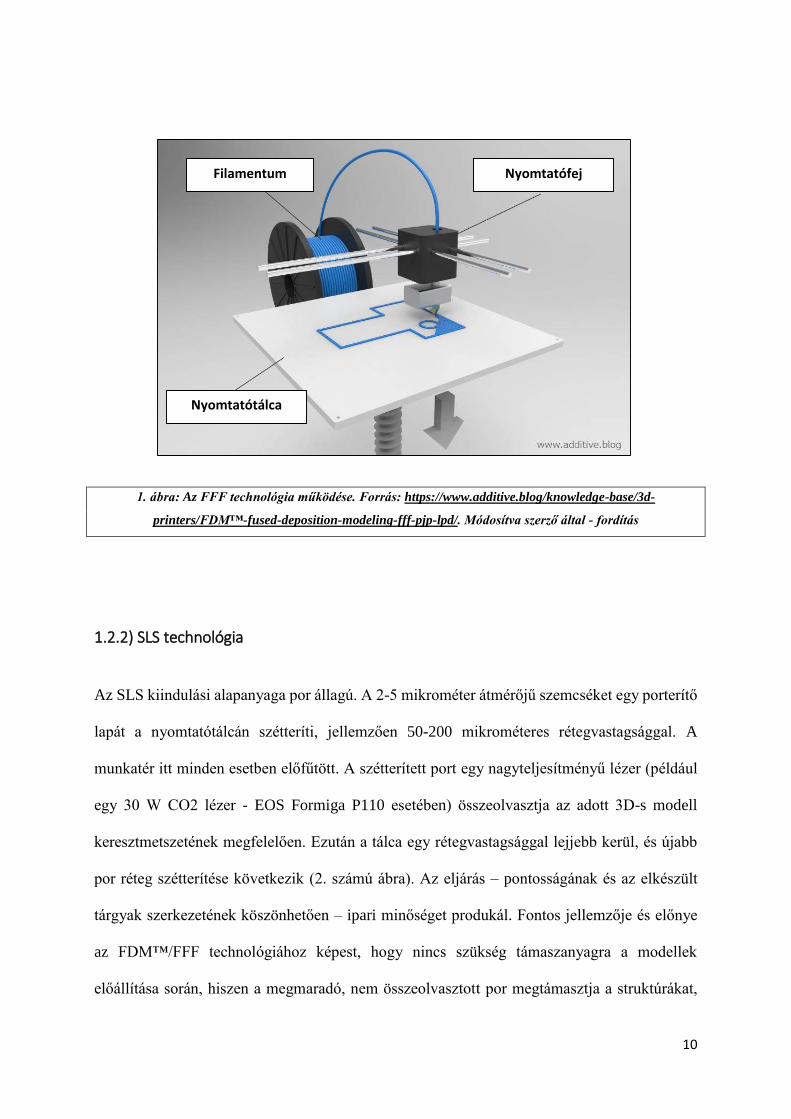
Az SLS kiindulási alapanyaga por állagú. A 2-5 mikrométer átmérőjű szemcséket egy porterítő
lapát a nyomtatótálcán szétteríti, jellemzően 50-200 mikrométeres rétegvastagsággal. A
munkatér itt minden esetben előfűtött. A szétterített port egy nagyteljesítményű lézer (például
egy 30 W CO2 lézer - EOS Formiga P110 esetében) összeolvasztja az adott 3D-s modell
keresztmetszetének megfelelően. Ezután a tálca egy rétegvastagsággal lejjebb kerül, és újabb
por réteg szétterítése következik (2. számú ábra). Az eljárás – pontosságának és az elkészült
tárgyak szerkezetének köszönhetően – ipari minőséget produkál. Fontos jellemzője és előnye
az FDM™/FFF technológiához képest, hogy nincs szükség támaszanyagra a modellek
előállítása során, hiszen a megmaradó, nem összeolvasztott por megtámasztja a struktúrákat,
Nyomtatófej
Nyomtatótálca
Filamentum
11
ezáltal komplex térformák is létrehozhatók segítségével. Az ipari méretű berendezések mellett
megjelentek kisebb, asztali méretű társaik is (például: Lisa Sinterit), melyek költséghatékony
módon biztosítják a prototípizálást és a kis-szériás gyártást. Az alapanyag itt poliamid (PA)
illetve ennek keverékei például üvegporral (pl: PA 3200 GF) vagy karbonnal. A poliamidot
kedvező mechanikai tulajdonságai, ára, és biokompatibilitása az orvostechnológiai fejlesztések
meghatározó szereplőjévé teszi.
2.ábra: Az SLS techológia működése. Forrás: https://www.makexyz.com/printer-services/process/SLS-3D-
printing-services. Módosítva szerző által - fordítás
1.2.3) PolyJet™ technológia
A PolyJet™ technológiát a Stratasys (Eden Prairie, Minnesota, Egyesült Államok) nevű vállalat
szabadalmaztatta. Hasonlóan a DLP vagy SLA eljárásokhoz, a kiindulási alapanyag ebben az
esetben folyékony halmazállapotú fotopolimer, melyet a nyomtatófej juttat a tálcára (3. számú
Nyomtatott tárgy
Nyomtató-
tálca
Tükör
Lézer Porterítő
Por
Alapanyag-tartály Munka-tartály

12
ábra). A fotopolimerek ezen eljárások esetében UV fény vagy lézerfény hatására
polimerizálódnak, szilárdulnak meg. Míg az SLA és DLP technológiájú gépek esetében ez
általában egyfajta anyag és szín felhasználását teszi lehetővé, a PolyJet™™ technológia
sajátossága, hogy egyszerre több féle fotopolimert képes összekeverni, ezáltal egy adott
objektumban, tárgyban lehetséges egészen puha, rugalmas és kemény anyagok egyidejű
felhasználása, illetve egyes berendezések (pl.: Stratasys J750) akár több tízezer szín
nyomtatására is képesek. A támaszanyag (support) itt minden esetben kimosható, ezért
viszonylag komplex formák is nyomtathatók vele. Felbontása kiemelkedően magas, képes akár
a 16 mikrométeres rétegvastagság előállítására is. Utókezelést (például UV kamra) nem
igényel, ez is előnye a standard SLA/DLP eljárásokhoz képest. A felhasználható alapanyagok
széles tárháza lehetővé teszi magas minőségű és valósághűségű modellek és mesterdarabok
előállítását, valamint funkcionális prototípusok legyártását.
3. ábra: PolyJet™ technológia működése. Forrás: Udroiu et al 2017: PolyJet™ technology for rapid tooling
[20]https://www.researchgate.net/publication/318112255_PolyJet™_technology_applications_for_rapid_tooli
ng. Módosítva szerző által - fordítás
Modell anyaga Támaszanyag
Nyomtatótálca
UV
lámpa UV
fény
Nyomtatófej X tengely
UV
lámpa
Z tengely
Y tengely
13
1.2.4) 4D nyomtatás
Az egészségügyben – ahogy az iparban is – kiemelkedő fontosságúak lesznek az úgynevezett
„intelligens” anyagok, melyek különböző környezeti hatásokra képesek változtatni
szerkezetükön, formájukon. A környezeti hatások között szerepelhet például a hőmérséklet
vagy a páratartalom, esetleg az elektromos tér. Az SMP-k (shape memory polymer –
„alakemlékező polimer”) és SMA-k (shape memory alloy – „alakemlékező ötvözet”) eltérő
környezetben eltérő térbeli konformációt képesek felvenni, így kiválóan alkalmazhatók orvosi
eszközök előállításában: stentek [21, 22] vagy soft-robotikai alkatrészek megalkotásában
széleskörű lehetőségeket biztosítanak a fejlesztőknek, gyártóknak. Ilyen tárgyakat [23] már 3D
nyomtatási technológia segítségével is megalkothatunk [24, 25]. Ezen technológiák és anyagok
felhasználásával a felső végtagi protetikában is használt aktuátorokat és mesterséges izmokat is
előállítottak [26, 27], de alkalmazható hallókészülékek innovációjában is [27]. A 3D nyomtatott
SMP-k valamint SMA-k alkalmazása egy forrongó terület, PolyJet™ technológiával sikeresen
állítottak elő már ilyen próbatesteket és kisebb tárgyakat [28, 29], valamint elektronikai
fejlesztésekben is értek el vele előremutató eredményeket [30]
14
2.) Elméleti alapok
2.1) Additív gyártástechnológiai megoldások az egészségügyben
A 3D nyomtatási technológiák megjelenése az egészségügyben mind a prevenció, mind a
diagnosztika, mind az ellátás és a rehabilitáció területén számos újítást hozott. Ezek
hozzájárulnak az egészségügyi oktatás hatékonyságának növeléséhez, a diagnosztikus és
intervenciós lépések rövidüléséhez, a páciensek életminőségének javulásához, ezáltal pedig
társadalmi szinten az egészségnyereség növekedéséhez.
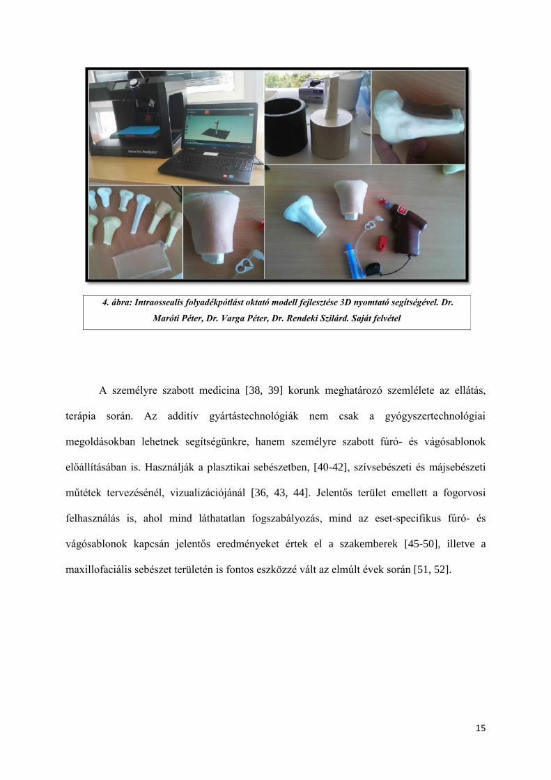
Az egészségügyi felsőoktatásban (orvos- és egészségügyi szakdolgozó képzés) az
anatómia és patológia oktatása a legkézenfekvőbb példa, [31-35], azonban kiemelten fontos
terület a prevenció, a betegedukáció és az orvos-beteg kommunikáció elősegítése, támogatása
is [36, 37]. A 3D modelleket felhasználva biztosítva van a költséghatékony, reprodukálható
gyártás (4. számú ábra), a modellek nagysága, részletgazdagsága tetszőlegesen variálható,
illetve a 3D nyomtatási fájlok megoszthatók. Technológiától függően a fontosabb részek
kiemelhetők (szín, nyomtatási minőség), elősegítve a hatékony vizualizációt és
kommunikációt.
15
A személyre szabott medicina [38, 39] korunk meghatározó szemlélete az ellátás,
terápia során. Az additív gyártástechnológiák nem csak a gyógyszertechnológiai
megoldásokban lehetnek segítségünkre, hanem személyre szabott fúró- és vágósablonok
előállításában is. Használják a plasztikai sebészetben, [40-42], szívsebészeti és májsebészeti
műtétek tervezésénél, vizualizációjánál [36, 43, 44]. Jelentős terület emellett a fogorvosi
felhasználás is, ahol mind láthatatlan fogszabályozás, mind az eset-specifikus fúró- és
vágósablonok kapcsán jelentős eredményeket értek el a szakemberek [45-50], illetve a
maxillofaciális sebészet területén is fontos eszközzé vált az elmúlt évek során [51, 52].
4. ábra: Intraossealis folyadékpótlást oktató modell fejlesztése 3D nyomtató segítségével. Dr.
Maróti Péter, Dr. Varga Péter, Dr. Rendeki Szilárd. Saját felvétel
16
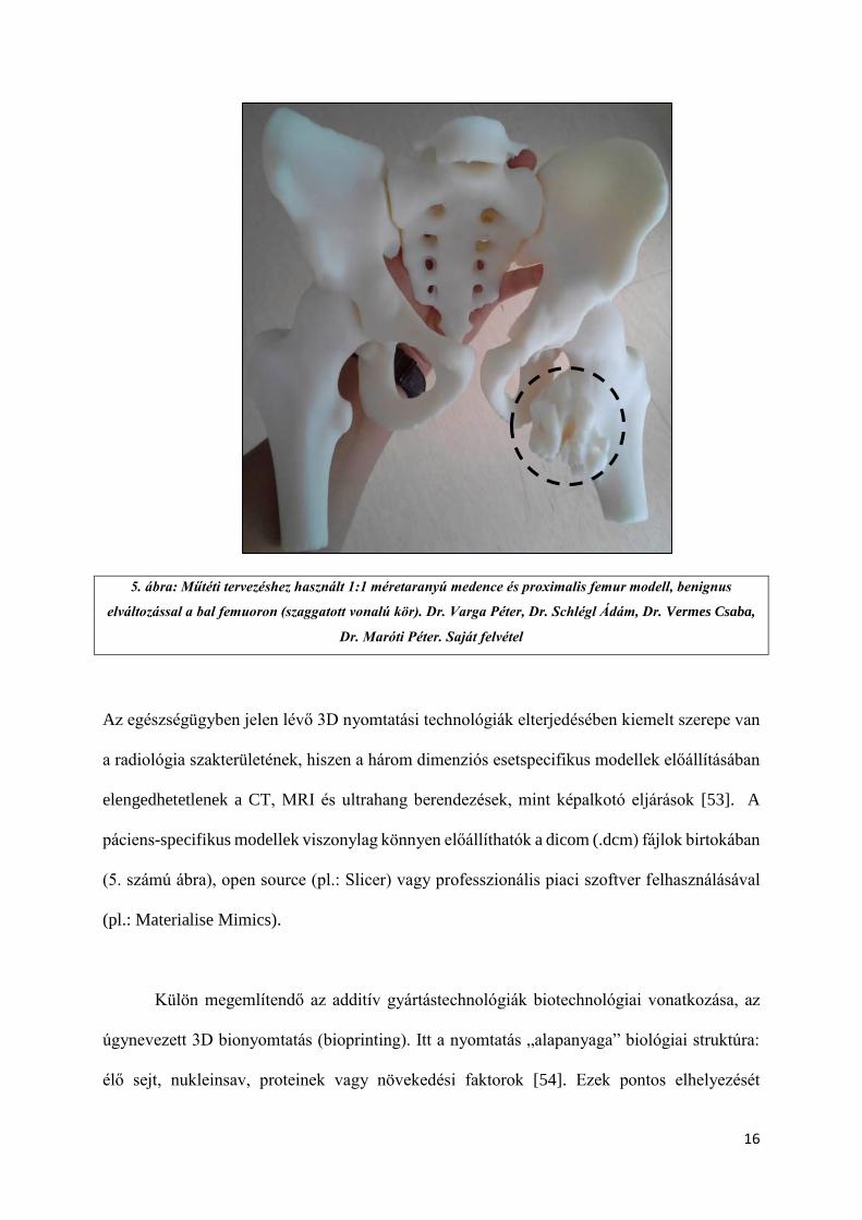
5. ábra: Műtéti tervezéshez használt 1:1 méretaranyú medence és proximalis femur modell, benignus
elváltozással a bal femuoron (szaggatott vonalú kör). Dr. Varga Péter, Dr. Schlégl Ádám, Dr. Vermes Csaba,
Dr. Maróti Péter. Saját felvétel
Az egészségügyben jelen lévő 3D nyomtatási technológiák elterjedésében kiemelt szerepe van
a radiológia szakterületének, hiszen a három dimenziós esetspecifikus modellek előállításában
elengedhetetlenek a CT, MRI és ultrahang berendezések, mint képalkotó eljárások [53]. A
páciens-specifikus modellek viszonylag könnyen előállíthatók a dicom (.dcm) fájlok birtokában
(5. számú ábra), open source (pl.: Slicer) vagy professzionális piaci szoftver felhasználásával
(pl.: Materialise Mimics).
Külön megemlítendő az additív gyártástechnológiák biotechnológiai vonatkozása, az
úgynevezett 3D bionyomtatás (bioprinting). Itt a nyomtatás „alapanyaga” biológiai struktúra:
élő sejt, nukleinsav, proteinek vagy növekedési faktorok [54]. Ezek pontos elhelyezését
17
biokompatiblis polimer-mátrixban szükséges megtenni, ilyen például a PEGDMA (polietilén-
glikol-dimetakrilát), a PCL (polikaprolakton) de a nyomtatás történhet hidrogélekbe is.
Nemzetközi kutatócsoportok már sikeresen állítottak elő csont [55]-és porcszövetet [56],
májszövetet[57] de szívbillentyű nyomtatás [58] és bőrnyomtatás [59] terén is kimagasló
sikereket értek el kutatók. A kinyomtatott biológiai struktúrák nem csak a gyógyszeriparban –
mint új, állat- és humán klinikai vizsgálatokat helyettesítő modellek – jelentenek áttörést,
hanem a szervtranszplantációban is.
18
2.2) A 3D nyomtatás gyakorlati aspektusai az egészségügyben
2.2.1) 3D nyomtatási fájlok:
A nyomtatáshoz elengedhetetlen a kiindulási 3D modell. Ehhez több módon is hozzájuthatunk.
A legegyszerűbb esetben ingyenes internetes adatbázisokból (pl.: Thingiverse) való letöltés
jöhet szóba, ilyenkor szinte semmilyen módosításra nincs szükség az előre elkészített, és a
felhasználók által feltöltött modellekben. A nyomtatásra előkészített fájlok bizonyos esetekben
.obj, de leggyakrabban .stl formátumúak. Az obj (object) fájlok 3D-s modellezésben
általánosabban használt kiterjesztések, melyek 3D-s adatokat, információkat tartalmaznak az
adott objektumról, de egyes, nyomtatást előkészítő szeletelőprogramok is tudnak vele dolgozni.
Képes akár anyagtulajdonságok, színek és textúrák tárolására is, azonban dinamikus
jellemzőkkel (mozgás, fényviszonyok) nem bírnak. Az stl. (standard tessellation language)
fájlok, melyek a 3D nyomtatásban játszanak kiemelkedően fontos szerepet, csak felületeti,
geometriai adatokkal rendelkeznek a 3D modellt illetően, könnyen feldolgozhatók, ennek
megfelelően ez a leggyakoribb 3D nyomtatási fájlformátum. Amennyiben egyedi modell
elkészítése a cél, CAD (computer aided design) programok használatával lehet a tervezést
megtenni, ilyen például az AutoDesk™ termékcsalád, ezen tervezőszoftverek pedig közvetlen
.stl export funkcióval bírnak. Orvosi felhasználások esetén sok esetben szükséges CT, MR vagy
ultrahang adatokból (DICOM - .dcm) kinyerni a térbeli információt, melyet szegmentálással
lehet megtenni. Ezen esetekben is a végső fájl egy .stl kiterjesztésű adatcsomag lesz. A 3D
nyomtatásra szánt fájlokat (.stl vagy .obj) a nyomtató számára előzetesen „fel kell szeletelni”
(slicing) egy külön szoftver segítségével, így például „g-code”-okat hozunk létre, melyek a 3D
nyomtatók számára tartalmazzák a pontos térbeli információkat és az adott térbeli ponthoz
tartozó nyomtatási parancsot (6. számú ábra). A modellek elkészítését szinte minden esetben
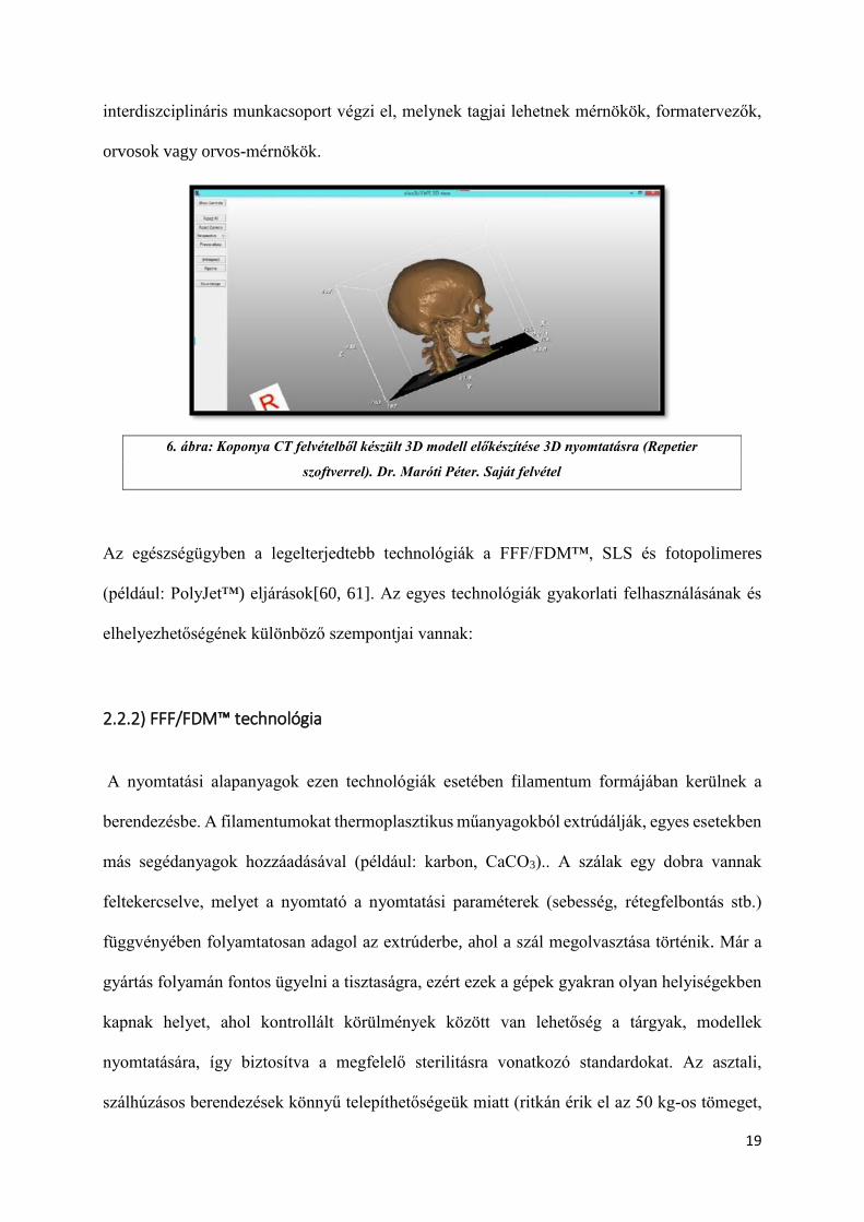
19
interdiszciplináris munkacsoport végzi el, melynek tagjai lehetnek mérnökök, formatervezők,
orvosok vagy orvos-mérnökök.
Az egészségügyben a legelterjedtebb technológiák a FFF/FDM™, SLS és fotopolimeres
(például: PolyJet™) eljárások[60, 61]. Az egyes technológiák gyakorlati felhasználásának és
elhelyezhetőségének különböző szempontjai vannak:
2.2.2) FFF/FDM™ technológia
A nyomtatási alapanyagok ezen technológiák esetében filamentum formájában kerülnek a
berendezésbe. A filamentumokat thermoplasztikus műanyagokból extrúdálják, egyes esetekben
más segédanyagok hozzáadásával (például: karbon, CaCO3).. A szálak egy dobra vannak
feltekercselve, melyet a nyomtató a nyomtatási paraméterek (sebesség, rétegfelbontás stb.)
függvényében folyamtatosan adagol az extrúderbe, ahol a szál megolvasztása történik. Már a
gyártás folyamán fontos ügyelni a tisztaságra, ezért ezek a gépek gyakran olyan helyiségekben
kapnak helyet, ahol kontrollált körülmények között van lehetőség a tárgyak, modellek
nyomtatására, így biztosítva a megfelelő sterilitásra vonatkozó standardokat. Az asztali,
szálhúzásos berendezések könnyű telepíthetőségeük miatt (ritkán érik el az 50 kg-os tömeget,
6. ábra: Koponya CT felvételből készült 3D modell előkészítése 3D nyomtatásra (Repetier
szoftverrel). Dr. Maróti Péter. Saját felvétel
20
illetve hálózati áramforrásról működtethetők, nem szükséges ipari áram hozzájuk) klinikai
körülmények között is jól használhatók. A nyomtatásra előkészített fájlt külső adathordozón
vagy hálózaton lehet a berendezéseknek elküldeni.
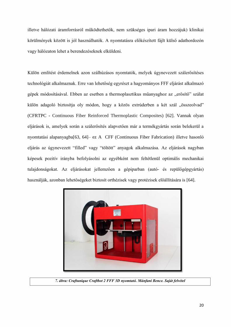
Külön említést érdemelnek azon szálhúzásos nyomtatók, melyek úgynevezett szálerősítéses
technológiát alkalmaznak. Erre van lehetőség egyrészt a hagyományos FFF eljárást alkalmazó
gépek módosításával. Ebben az esetben a thermoplasztikus műanyaghoz az „erősítő” szálat
külön adagoló biztosítja oly módon, hogy a közös extrúderben a két szál „összeolvad”
(CFRTPC - Continuous Fiber Reinforced Thermoplastic Composites) [62]. Vannak olyan
eljárások is, amelyek során a szálerősítés alapvetően már a termékgyártás során belekerül a
nyomtatási alapanyagba[63, 64]– ez A CFF (Continuous Fiber Fabrication) illetve hasonló
eljárás az úgynevezett “filled” vagy “töltött” anyagok alkalmazása. Az eljárások nagyban
képesek pozitív irányba befolyásolni az egyébként nem feltétlenül optimális mechanikai
tulajdonságokat. Az eljárásokat jellemzően a gépiparban (autó- és repülőgépgyártás)
használják, azonban lehetőségeket biztosít orthézisek vagy protézisek előállítására is [64].
7. ábra: Craftunique Craftbot 2 FFF 3D nyomtató. Mánfani Bence. Saját felvétel
21
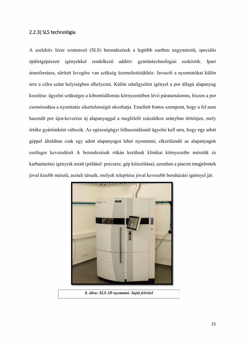
2.2.3) SLS technológia
A szelektív lézer szinterező (SLS) berendezések a legtöbb esetben nagyméretű, speciális
épületgépészeti igényekkel rendelkező additív gyártástechnológiai eszközök. Ipari
áramforrásra, sűrített levegőre van szükség üzemeltetésükhöz. Javasolt a nyomtatókat külön
erre a célra szánt helyiségben elhelyezni. Külön odafigyelést igényel a por állagú alapanyag
kezelése: ügyelni szükséges a kibontóállomás környezetében lévő páratartalomra, hiszen a por
csomósodása a nyomtatás sikertelenségét okozhatja. Emellett fontos szempont, hogy a fel nem
használt por újra-keverése új alapanyaggal a megfelelő százalékos arányban történjen, mely
értéke gyártónként változik. Az egészségügyi felhasználásnál ügyelni kell arra, hogy egy adott
géppel általában csak egy adott alapanyagot lehet nyomtatni, elkerülendő az alapanyagok
esetleges keveredését A berendezések ritkán kerülnek klinikai környezetbe méretük és
karbantartási igényeik miatt (például: porcsere, gép kitisztítása), azonban a piacon megjelentek
jóval kisebb méretű, asztali társaik, melyek telepítése jóval kevesebb beruházási igénnyel jár.
8. ábra: SLS 3D nyomtató. Saját felvétel
22
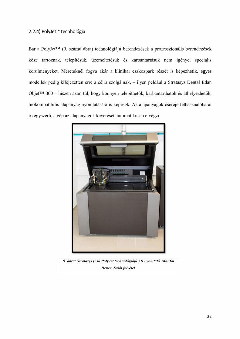
2.2.4) PolyJet™ tecnhológia
Bár a PolyJet™ (9. számú ábra) technológiájú berendezések a professzionális berendezések
közé tartoznak, telepítésük, üzemeltetésük és karbantartásuk nem igényel speciális
körülményeket. Méretüknél fogva akár a klinikai eszközpark részét is képezhetik, egyes
modellek pedig kifejezetten erre a célra szolgálnak, – ilyen például a Stratasys Dental Edan
Objet™ 360 – hiszen azon túl, hogy könnyen telepíthetők, karbantarthatók és áthelyezhetők,
biokompatibilis alapanyag nyomtatására is képesek. Az alapanyagok cseréje felhasználóbarát
és egyszerű, a gép az alapanyagok keverését automatikusan elvégzi.
9. ábra: Stratasys j750 PolyJet technológiájú 3D nyomtató. Mánfai
Bence. Saját felvétel.
23
2.3) Polimerek biokompatibilitása orvosi eszközfejlesztés esetén
A biokompatibilitás fogalma elsősorban a beültethető implantátumok kapcsán merült fel, már
az 1940-es években. [65] Bár több definíció is megadható, mindegyikre igaz, hogy a
biokompatibilitás a különböző anyagok (polimerek, fémek, ötvözetek, kompozitok stb.) és a
különböző élő struktúrák (sejtalkotók, sejtek, szövetek, szervrendszerek) közötti kémiai,
biológiai és fizikai kapcsolatot írja le. A biokompatibilitás az orvosi eszközfejlesztés kapcsán
szinte minden területen kiemelt fontosságú: sebészeti eszközök, fúró-vágósablonok,
implantátumok, gyógyszer- vagy hatóanyag leadó beültethető eszközök, endoprotézisek,
mikrofluidikai eszközök, mesterséges szervek (például műbillentyű), illetve a különböző
ortézisek és protézisek [66] tervezése, gyártása és szállítása, tárolása és beültetése során
egyaránt meghatározó szempont.
A biokompatibilitást számos tényező befolyásolja az anyag oldaláról. Ezek egyrészt lehetnek
szerkezeti jellemzők – ilyen például a porozitás, felületi jellemzők – befolyásoló tényező lehet
az anyag összetétele, például víztartalma és a bomlásakor felszabaduló anyagok egyaránt. Ezen
tényezők mellett számos paraméter befolyásolja egy-egy anyag viselkedését és kölcsönhatását
az élő szervezettel, melyet az alábbiakban foglalhatunk össze [67] :
Fizikai jellemzők: összetétel, porozitás, kristályszerkezet, víztartalom
Felületi jellemzők: topográfia, kémiai jellemzők, energia, molekuláris mobilitás,
elektromos jellemzők, hidrofób/hidrofil tulajdonságok
Degradáció: kinetika, köztes- és végtermékek, toxicitás
Szennyező- vagy segédanyagok: keverő- és adalékanyagok, szennyező anyagok,
asszociált toxikus anyagok
24
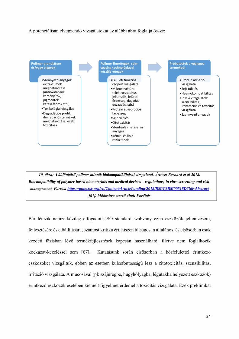
A potenciálisan elvégzendő vizsgálatokat az alábbi ábra foglalja össze:
10. ábra: A különböző polimer minták biokompatibilitásai vizsgálatai. Átvéve: Bernard et al 2018:
Biocompatibility of polymer-based biomaterials and medical devices – regulations, in vitro screening and risk-
management. Forrás: https://pubs.rsc.org/en/Content/ArticleLanding/2018/BM/C8BM00518D#!divAbstract
[67]. Módosítva szerző által: Fordítás
Bár létezik nemzetközileg elfogadott ISO standard szabvány ezen eszközök jellemzésére,
fejlesztésére és előállítására, számost kritika éri, hiszen túlságosan általános, és elsősorban csak
kezdeti fázisban lévő termékfejlesztések kapcsán használható, illetve nem foglalkozik
kockázat-kezeléssel sem [67]. Kutatásunk során elsősorban a bőrfelülettel érintkező
eszközöket vizsgáltuk, ebben az esetben kulcsfontosságú lesz a citotoxicitás, szenzibilitás,
irritáció vizsgálata. A mucosával (pl: szájüregbe, húgyhólyagba, légutakba helyezett eszközök)
érintkező eszközök esetében kiemelt figyelmet érdemel a toxicitás vizsgálata. Ezek preklinikai
Polimer granulátum és/vagy elegyek
•Szennyező anyagok, extraktumok meghatározása (antioxidánsok, keményítők, pigmentek, katalizátorok stb.)
•Toxikológiai vizsgálat
•Degradációs profil, degradációs termékek meghatározása, ezek toxicitása
Polimer fimrétegek, spin-coating technológiával készült rétegek
•Felületi funkciós csoport vizsgálata
•Mikrostruktúra (elektrosztatikus jellemzők, felületi érdesség, dagadás-duzzadás, stb.)
•Protein abszorpciós képesség
•Sejt túlélés
•Citotoxicitás
•Sterilizálás hatásai az anyagra
•Kémiai és lipid rezisztencia
Próbatestek a végleges termékből
•Protein adhézió vizsgálata
•Sejt túlélés
•Heamokompatibilitás
•In vivi vizsgálatok: szenzibilitás, irritátációs és toxicitás vizsgálata
•Szennyező anyagok

25
tesztelése – a megfelelő állatetikai engedélyek birtokában – általában nyulakon,
tengerimalacokon történik.
Az egyes polimerek viselkedésük alapján az alábbi kategóriákba sorolhatók:
„Biostable” – biostabil, biológiailag nem lebomló/felszívódó
„Bioadsorbable” – biológiailag lebomló/felszívódó
„Partially Bioadsorbable”- biológiailag részben lebomló/felszívódó
Az polimerek és az élő szervezet közötti kapcsolat ideje is döntő fontosságú, ez alapján az
alábbi kategóriákat különíthetjük el:
Ultra rövid idejű: kevesebb, mint 24 óra
Rövid idejű: 24 óra – 30 nap
Permanens, állandó: 30 napon túli.
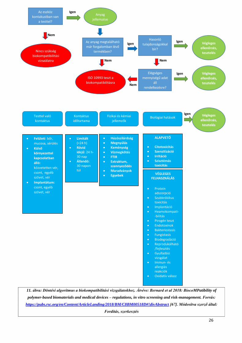
Összefoglalva, Bernard és munkatársai (2018) [67] az alábbi döntési algoritmust javasolják a
biokompatibilitási vizsgálatok kivitelezésére:
26
Igen
Igen Igen
Igen
Igen
Nem
Nem Nem
Nem
Az eszköz
kontakustban van
a testtel?
Anyag
jellemzése
Az anyag megtalálható
már forgalomban lévő
termékben?
Hasonló
tulajdonságokkal
bír?
ISO 10993 teszt a
biokompatibilitásra
Elégséges
mennyiségű adat
áll
rendelkezésre?
Végleges
ellenőrzés,
tesztelés
Végleges
ellenőrzés,
tesztelés
Kontaktus
időtartama
Testtel való
kontaktus Biológiai hatások Fizikai és kémiai
jellemzők
Végleges
ellenőrzés,
tesztelés
Felületi: bőr,
mucosa, sérülés
Külső
környezettel
kapcsolatban
álló:
közvetetten vér,
csont, egyéb
szövet, vér
Implantátum:
csont, egyéb
szövet, vér
Limitált (<24 h)
Rövid idejű: 24 h- 30 nap
Állandó: 30 napon túl
Húzószilárdság
Megnyúlás
Keménység
Vízmegkötés
FTIR
Extraktum, szennyeződés
Maradványok
Egyebek
ALAPVETŐ
Citotoxicitás
Szenzitizáció
Irritáció
Szisztémás toxicitás
VÉGLEGES FELHASZNÁLÁS
Protein adszorpció
Szubkrókikus toxicitás
Implantáció
Heamokompati--bilitás
Pirogén teszt
Endotoxinok
Bakteriostasis
Fungistasis
Biodegradáció
Reprodukálható/fejlesztés
Gyulladási vizsgálat
Immun- és allergiás reakciók
Oxidatív válasz
Nincs szükség
biokompatibilitási
vizsgálatra
11. ábra: Döntési algoritmus a biokompatibilitási vizsgálatokhoz. Átvéve: Bernard et al 2018: BiocoMPatibility of
polymer-based biomaterials and medical devices – regulations, in vitro screening and risk-management. Forrás:
https://pubs.rsc.org/en/Content/ArticleLanding/2018/BM/C8BM00518D#!divAbstract [67]. Módosítva szerző által:
Fordítás, szerkesztés
27
2.4) Vizsgálataink célja, problémafelvetés
Kutatásunk célja az orvosi eszközfejlesztésben használható, 3D nyomtatási alapanyagok átfogó
vizsgálata volt, mechanikai, szerkezeti és termoanalitikai szempontokból egyaránt. A 3D
nyomtatási technológiák közül szinte mindegyiknek vannak orvosi, egészségtudományi
vonatkozásai. Kutatócsoportunk a leggyakrabban használt szálhúzásos (FDM™/FFF),
szelektiv lézer szinterezési (SLS) és fotopolimeres eljárásokat elemezte, ezen belül fókuszálva
a Stratasys PolyJet™ technológiára. A vizsgálatokat gyakorlati felhasználási problémákon
keresztül vezettük végig, melyek orvostechnikai eszközök és segédeszközök prototípus-
fejlesztése kapcsán merültek fel. A szerkezettani és mechanikai vizsgálatokat exoprotetikai és
robotikai fejlesztések során végeztük el, a termoanalitikai elemzéseket olyan anyagok esetében
tettük meg, ahol a hőhatás számottevő befolyásoló faktor lehet a felhasználás során. Emellett
fontos kérdésként merült fel az alapanyagok kiindulási formájának (pelletek) hőtani analízise
is. A fotopolimeres eljárások tekintetében pedig egy fogorvosi, szájsebészeti felhasználás volt
vizsgálatunk tárgya, melyeknél a biokompatibilitás és a pontosság a meghatározó tényezők.
További célkitűzésünk, hogy egy magyar nyelvű dolgozat formájában átfogó ismertetést adjunk
a jelenleg hazánkban leginkább elterjedt technológiák vonatkozásában.
2.4.1) 3D nyomtatott törésrögzítések:
A felső végtagi sérülések a leggyakoribb töréstípusok közé tartoznak hazai és nemzetközi
szinten egyaránt [68, 69]. A végtag megfelelő rögzítése elengedhetetlen a teljes funkcionalitás
visszanyeréséhez. A hagyományos rögzítési eljárás azonban kellemetlenségekkel járhat a
páciens szempontjából: viselése nehézkes, viszonylag nagy tömeggel rendelkezik, emellett a
tisztálkodást is kényelmetlenné, részben lehetetlenné teszi. A 3D nyomtatással készült,
műanyag vagy kompozit alapú törésrögzítések azonban ezen hátrányokat kiküszöbölhetik,
28
hiszen vízállók, tömegük szinte elenyésző, illetve megfelelő stabilitást adnak a felső végtag
teljes rehabilitációjáig. A 3D nyomtatott törésrögzítések vonatkozásában több nemzetközi
tanulmány is megjelent, melyek elsősorban a 3D szkennelési és 3D modellezési lehetőségeket
vizsgálják [70, 71], illetve, összevetnek különböző technológiákat is, [72] azonban kevés
tudományos igényű információ áll rendelkezésre a potenciálisan felhasználható
alapanyagokról, illetve fontos gyakorlati kérdésekről, mint például a tervezési és előállítási idő
vagy a költséghatékonyság. Ennek megfelelően fontosnak tartottuk, hogy két egyedi
fejlesztésű, a piacon megjelent alapanyagot megvizsgáljunk a gyakorlati használhatóság
szempontjából termonalitikai és mechanikai szempontból egyaránt. A kísérletek során 3D
modellezés alapján nyomtatott, és thermoformázással véglegesített modelleket is teszteltük.
2.4.2) 3D nyomtatott felső végtagi protézisek
Kutatócsoportunk 3D nyomtatással előállított felső végtagi fejlesztésével is foglalkozik. A felső
végtagi amputációk milliókat érintenek világszerte. A felső végtagi amputációval élők
életminőségét nagyban javíthatják [73] a magas funkcionalitással bíró végtagprotetikai
eszközök, azonban ezek jelentős anyagi terhet róhatnak az egészségügyi ellátórendszerre illetve
az adott kliensre egyaránt. A felső végtagi protézisek gyakorlati szempontból feloszthatók
esztétikai és funkcionális protézisekre. Míg az esztétikai céllal készült segédeszközök fő célja,
hogy a kliens egy valósághű, részletesen kidolgozott modellt viselhessen a mindennapokban,
hozzájárulva az egészséges testkép kialakításához, a funkcionális eszközök a mindennapi
tevékenységek – például: étkezés, öltözködés, gépelés – elvégzésében is segítenek. Ezen
csoport legegyszerűbb képviselői a mechanikus protézisek, melyek az ép kézzel, vagy a tok
feletti, meglévő ízület mozgatásával hozhatók működésbe, mechanikus elven (például zsinórok
segítségével). A fejlettebb, myoelektromos eszközök felszíni elektródák segítségével
irányíthatók, melyek a bőrfelületről vezetik el az izmok által generált elektromos potenciált.
29
Ezek a modellek több szabadsági fokkal és precizitással rendelkeznek, mint mechanikus társaik.
A funkcionális protézisek kapcsán elektroenkefalográfiás vezérléssel is folynak tudományos
kísérletek, illetve direkt neuron elvezetéssel is, de ezek a piacon még nem elérhetőek. A 3D
nyomtatási eljárások a felső és alsó végtagi protézisek gyártásában is jelenetős segítséget
nyújthatnak, részben költséghatékonyságukkal, részben pedig az egyedi darabok, alkatrészek
előállításával. Világszerte számos interdiszciplináris kutatócsoport dolgozik azon, hogy a
kliensek számára elérhető, a mindennapi tevékenységeket elősegítő eszközt készítsenek
(AODL), illetve jelentős az úgynevezett open source megoldások elterjedése is (E-NABLE [74]
Thingiverse [75]) [76-79]. Az irodalmi adatok áttekintése valamint a piackutatás során
felmerült, hogy a gyártás szempontjából nincsenek pontos ismereteink a legoptimálisabb, 3D
nyomtatásban használható alapanyagokról, eljárásokról és nyomtatási orientációkról ezen a
területen. A legtöbb eszköz FDM™/FFF technológiával került leírásra, azonban más 3D
nyomtatási eljárások is ígéretesek lehetnek [80], ezért felmerült az egyes, potenciálisan szóba
jöhető technológiák összehasonlításának igénye.
2.4.3) Phoenix Smart Orthosis:
A stroke (agyvérzés) összesen 17 millió embert érint világszerte [81]. Az USA-ban ez
körülbelül 800.000, míg az Európai Unióban 615.000 új pácienst jelent évente [82]. A betegség
felelős a felnőttkori rokkant állapotok többségéért, és a páciensek mindösszesen 40-50% képes
részben visszatérni munkájához az agyi érkatasztrófát követően [83, 84]. A felső végtagot érintő
funkcióromlások közül a post-stroke-os páciensek felső végtagját érintő spasztikus állapotok
jelentősek. Ez egyrészt csökkenti az életminőséget, nehezíti a napi tevékenységek (AODL –
activities of daily living) ellátását, mint például a tisztálkodás, öltözködés vagy akár
táplálkozás. Ezen állapotok javítására, rehabilitációjára több eljárás és berendezés is létezik,
azonban ezek leginkább klinikai körülményekre optimalizáltak, és nem tömeggyártásra szánt,
30
a mindennapokban a páciensek számára készített eszközök. Fejlesztésünk során kiemelt
szempont volt olyan gyártástechnológiai kérdések megválaszolása, melyek elengedhetetlenek
a költséghatékony prototípus- és szériagyártás megkezdéséhez.
2.4.4) Fogorvosi fúrófeltét készítése:
A harmadik moláris fog (bölcsességfog) és koronájának eltávolítása az egyik leggyakoribb
szájsebészeti beavatkozás. A 3D nyomtatás a maxillofaciális sebészet területén is jelentős
segítséget nyújthat. Az orvosi eszközök, segédeszközök fejlesztésének területén itt mutatkozik
meg talán a legnagyobb igény a precizitásra, az idegsebészeti és onkológiai eszközök mellett.
A pontos alkatrészek elkészítése segítheti a beavatkozások sikerességét. Ez különösen igaz a
harmadik molaris coronectomiák elvégzésénél, ahol a leggyakoribb probléma a gyökér-
mobilizálás, mely az eljárás sikertelenségét okozhatja [85, 86]. Ennek megfelelően az ilyen
irányú készségeket oktató szakorvos-képzés kiemelt fontosságú [87], illetve ennek eszközös
támogatása személyre szabott, beavatkozást támogató fúrófeltét alkalmazásával nagyban
csökkentheti az esetleges szövődményeket, a műtét eredménytelenségének kockázatát, ezáltal
hozzájárulva a páciens biztonságának növekedéséhez, illetve az egészségnyereség
fokozódásához.
31
3.) Módszerek és alapanyagok
3.1) 3D nyomtatási technológiák, próbatestek és minták előkészítése
A polimerek és kompozitok mechanikai és szerkezettani vizsgálatának elvégzéséhez standard
próbatesteket készítettünk, ISO és ASTM szabványok alapján. A szerkezeti vizsgálatok esetén
a próbatestek törési felszíneit vizsgáltuk. Kutatásunk során az alábbi technológiákat és
anyagokat elemeztük:
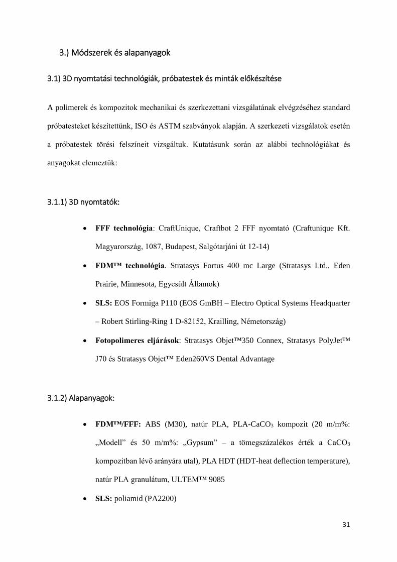
3.1.1) 3D nyomtatók:
FFF technológia: CraftUnique, Craftbot 2 FFF nyomtató (Craftunique Kft.
Magyarország, 1087, Budapest, Salgótarjáni út 12-14)
FDM™ technológia. Stratasys Fortus 400 mc Large (Stratasys Ltd., Eden
Prairie, Minnesota, Egyesült Államok)
SLS: EOS Formiga P110 (EOS GmBH – Electro Optical Systems Headquarter
– Robert Stirling-Ring 1 D-82152, Krailling, Németország)
Fotopolimeres eljárások: Stratasys Objet™350 Connex, Stratasys PolyJet™
J70 és Stratasys Objet™ Eden260VS Dental Advantage
3.1.2) Alapanyagok:
FDM™/FFF: ABS (M30), natúr PLA, PLA-CaCO3 kompozit (20 m/m%:
„Modell” és 50 m/m%: „Gypsum” – a tömegszázalékos érték a CaCO3
kompozitban lévő arányára utal), PLA HDT (HDT-heat deflection temperature),
natúr PLA granulátum, ULTEM™ 9085
SLS: poliamid (PA2200)
32
PolyJet™: Objet™Vero Grey™, Objet™ Digital ABS és MED670
VeroDent™
A próbatestekből a vizsgálati szabványoknak megfelelően 5-5 darab készült, az alábbi
nyomtatási paraméterekkel:
3.1.3) Nyomtatási paraméterek:
Az FDM™ és FFF 3D nyomtatóknál a nyomtatási hőmérséklet alapvető fontosságú a
végeredmény szempontjából. Vizsgálataink során az FDM™ technológia esetén, az ABS M30
alapanyagnál 250 °C,-ot és felfűtött nyomtatási kamrát használtunk, míg az ULTEM™
alapanyag esetében 350-400 °C közötti értéket választottunk (a pontos hőmérséklet
gyártói/forgalmazói titok). A rétegvastagság (Z irányú felbontás) előbbi esetben 0,178 mm és
0,330 mm volt, míg utóbbi esetben pedig 0,254 mm. FFF technológia esetén egységesen 215
°C extrúder hőmérsékletet alkalmaztunk 0,10 mm-es rétegfelbontással. A tálcahőmérséklet 60
°C volt. A próbatestek kitöltöttsége minden esetben 100%-ra volt állítva. A szálhúzási
sebességet 1,5 mm/s, a nyomtatófej X-Y irányú mozgási sebességét 60mm/s sebességre
kalibráltuk be.
Az SLS technológia kapcsán a poliamid próbatesteket 186 °C-os hőmérsékleten olvasztottuk
össze, a rétegvastagság minden esetben 0,10 mm volt. A próbatestek kitöltöttségét 100%-s
értékre állítottuk.
A PolyJet™-es eljárásoknál a cseppátmérő 0,042 mm volt átlagosan, a rétegfelbontás pedig
0,03 mm az ABS alapanyag, míg 0,016 mm a Vero Grey™ és MED670 VeroDent™
33
alapanyag esetében. A nyomtatási hőmérsékelt mindvégig 70 °C-ra volt beállítva, a
próbatestek kitöltöttsége pedig 100%-os volt.
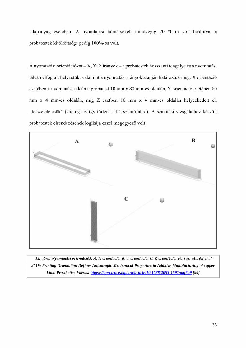
A nyomtatási orientációkat – X, Y, Z irányok – a próbatestek hosszanti tengelye és a nyomtatási
tálcán elfoglalt helyzetük, valamint a nyomtatási irányok alapján határoztuk meg. X orientáció
esetében a nyomtatási tálcán a próbatest 10 mm x 80 mm-es oldalán, Y orientáció esetében 80
mm x 4 mm-es oldalán, míg Z esetben 10 mm x 4 mm-es oldalán helyezkedett el,
„felszeletelésük” (slicing) is így történt. (12. számú ábra). A szakítási vizsgálathoz készült
próbatestek elrendezésének logikája ezzel megegyező volt.
12. ábra: Nyomtatási orientációk. A: X orientáció, B: Y orientáció, C: Z orientáció. Forrás: Maróti et al
2019: Printing Orientation Defines Anisotropic Mechanical Properties in Additive Manufacturing of Upper
Limb Prosthetics Forrás: https://iopscience.iop.org/article/10.1088/2053-1591/aaf5a9 [90]
34
3.2) DTA/TG – Termoanalitikai vizsgálatok
A termoanalatikai vizsgálatokhoz egy SC 5200 SII DTA/TG készüléket használtunk (Seiko,
Japán). A hőmérsékleti és entalpia kalibráció – szabvány szerint - Indium segítségével történt
(Alfa Aesar, PURA-TRONIC, Johnson Matthey CoMPany, Ward Hill, MA, USA), illetve a
hőmérsékleti paramétereket is a „Thermal Applications Note TA Instruments” szabványai
alapján választottuk meg (TN-11-[88]) A mintákat egy nyitott alumínium mintatartóban
helyeztük el, melyek átmérője 5 mm volt. A felfűtési sebességet 10-és 40 °C/min között
változtattuk, N2 gázzal telt munkatérben, mely áramlási sebessége 50 ml/min-re volt állítva. A
maximális hőmérsékleti érték 250 °C –t ért el. A hűlés folyamán külső hűtő egységet nem
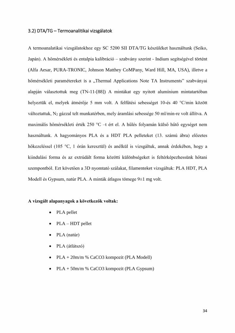
használtunk. A hagyományos PLA és a HDT PLA pelleteket (13. számú ábra) előzetes
hőkezeléssel (105 °C, 1 órán keresztül) és anélkül is vizsgáltuk, annak érdekében, hogy a
kiindulási forma és az extrúdált forma közötti különbségeket is feltérképezhessünk hőtani
szempontból. Ezt követően a 3D nyomtató szálakat, filamenteket vizsgáltuk: PLA HDT, PLA
Modell és Gypsum, natúr PLA. A minták átlagos tömege 9±1 mg volt.
A vizsgált alapanyagok a következők voltak:
PLA pellet
PLA – HDT pellet
PLA (natúr)
PLA (átlátszó)
PLA + 20m/m % CaCO3 kompozit (PLA Modell)
PLA + 50m/m % CaCO3 kompozit (PLA Gypsum)
35
A pellet forma esetében hőkezelt és nem hőkezelt mintákat is vizsgáltunk.
3.3) Statikus és dinamikus mechanikai vizsgálatok
Statikus mechanikai vizsgálatok közül a három pontos hajlító vizsgálatot végeztük el az ASTM-
D 790-3 szabvány szerint (2 mm / sec hajlítási sebességgel), illetve Shore D keménységet
mértünk (15 sec mérési idővel) az ASTM-D 2240-03 szabvány alapján. Utóbbi esetben minden
alkalommal a nyomtatótálca felöli oldalon mértük meg a próbatesteket. Emellett szakítópróbát
is végeztünk több technológia és anyag kapcsán, az ASTM-D 6378-03 szabványnak
megfelelően. A vizsgálatok elemszáma minden esetben 5 db volt, a szabványoknak
megfelelően. Dinamikus vizsgálatok közül Charpy ütővizsgálatot hajtottuk végre, bemetszés
nélkül, az ISO 179-1 szabvány szerint. Az alapanyagok vizsgálata során az egyes teszteket a
nyomtatandó tárgyak várható fizikai igénybevétele alapján választottuk meg, illetve a későbbi
13. ábra: NatureWorks Ingeo 3D850 PLA pellet. Forrás:
https://reprapworld.com/products/filament/pellets/natureworks_ingeo_3d850_natural_pla_pellets/
36
gyakorlati felhasználást vettük alapul. A vizsgálati helyiség hőmérséklete 27,1 °C volt, míg a
relatív páratartalom 48,8 %. A vizsgálat alapanyagok a következők voltak:
Három pontos hajlító vizsgálat esetén: PA, natúr PLA, PLA Gypsum, PLA Modell,
Objet™ Vero Grey™, Objet™ Digital ABS, ABS M30, ULTEM™ 9085
Shore D vizsgálat esetén: : PA, natúr PLA, PLA Gypsum, PLA Modell, Vero Grey™,
Objet™ Digital ABS ,ABS M30, ULTEM™ 9085
Szakítóvizsgálat esetén: natúr PLA, PLA Gypsum, PLA Modell
Charpy ütővizsgálat esetén: : PA, natúr PLA, PLA Gypsum, PLA Modell, Objet™
Vero Grey™, Objet™ Digital ABS, ABS M30, ULTEM™ 9085
Fontos megjegyzés, hogy az PLA natúr, PLA Gypsum, PLA Modell próbatestek esetén a
próbatesteket csak X orientációban nyomtattuk ki, hiszen a vizsgálatok célja kifejezetten 3D
nyomtatott törésrögzítések elkészítése volt, ezek előállítása az esetek döntő többségében
„fektetve” (X iránynak megfelelően) történik. Ez az állítás a thermoformázott módszerre
kifejezetten igaz.
3.4) Szerkezettani vizsgálatok SEM segítségével
A szerkezettani vizsgálatot scanning elektronmikroszkópia (SEM) segítségével végeztük el,
mely elterjedt vizsgálati módszer különböző alapanyagok szerkezetétek jellemzéséhez.
Vizsgálatainkhoz egy JEOL JSM 6300 típusú berendezést használtunk. A Charpy
ütővizsgálatoknál eltörtt próbatestek törési felszínét arannyal vontuk be, így láthatóvá téve a
struktúrájukat. Minden vizsgálati anyagot 15x, 60x és 200x nagyítással elemeztünk.
37
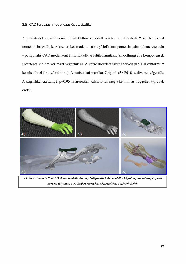
3.5) CAD tervezés, modellezés és statisztika
A próbatestek és a Phoenix Smart Orthosis modellezéséhez az Autodesk™ szoftvercsalád
termékeit használtuk. A kezdeti kéz modellt – a megfelelő antropometriai adatok lemérése után
– poligonális CAD modellként állítottuk elő. A felület simítását (smoothing) és a komponensek
illesztését Meshmixer™-rel végeztük el. A kézre illesztett eszköz terveit pedig Inventorral™
készítettük el (14. számú ábra.). A statisztikai próbákat OriginPro™ 2016 szoftverrel végeztük.
A szignifikancia szintjét p=0,05 határérétken választottuk meg a két mintás, független t-próbák
esetén.
14. ábra: Phoenix Smart Orthosis modellezése: a.) Poligonalis CAD modell a kézről b.) Smoothing és post-
process folyamat, c-e.) Eszköz tervezése, véglegesítése. Saját felvételek
38
4.) Eredmények
4.1) DTA/TG – Termoanalitikai vizsgálatok eredményei
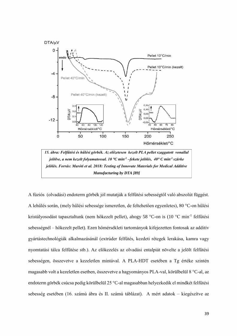
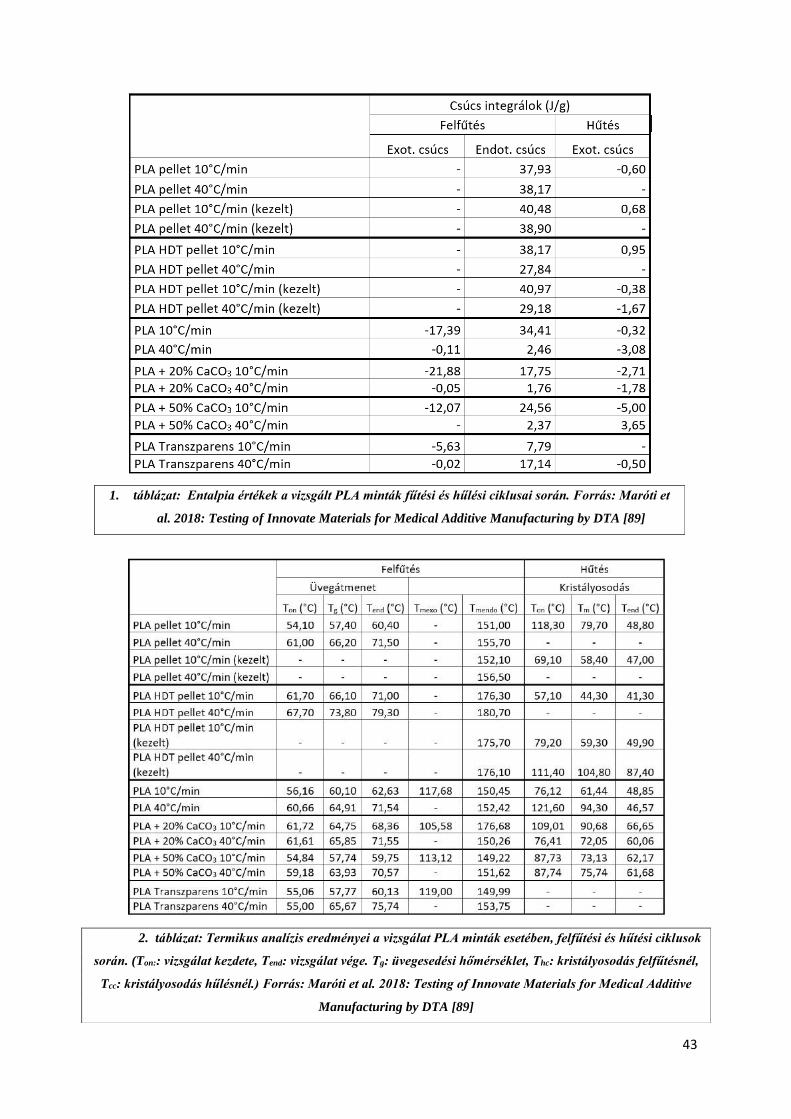
A vizsgálati eredmények összefoglalása az 1. és 2. számú táblázatokban láthatóa [89]. A
számolt entalpiaértékek – mely a vizsgált anyag belső rendszerétől függő, összes
energiatartalmat jelentik - a hőáram-görbék alatti terület integráljából határozhatók meg. A
görbéken elkülöníthetők az egyes fázisátmenetek, belső szerkezeti átalakulások. Az előzetes
hőkezelés a pelletek esetében a Tg (üveg-átmeneti hőmérséklet – glass transition temperature)
eltűnésével járt, minden felfűtési sebesség esetében. Érdekes megfigyelés, hogy egy váratlan
exoterm átmenet figyelhető meg ezen minták esetében (15. számú ábra), melyek az irodalmi
adatokban nem szerepelnek. Feltevésünk szerint ez lehet a pelletek gyártása során fellépő
környezeti hatások (páratartalom, alacsony koncentrációjú szennyeződés) eredménye.
39
A fúziós (olvadási) endoterm görbék jól mutatják a felfűtési sebességtől való abszolút függést.
A lehűlés során, (mely hűlési sebessége ismeretlen, de feltehetően egyenletes), 80 °C-on hűlési
kristályosodást tapasztaltunk (nem hőkezelt pellet), ahogy 58 °C-on is (10 °C min-1 felfűtési
sebességnél – hőkezelt pellet). Ezen hőmérsékleti tartományok kifejezetten fontosak az additív
gyártástechnológiák alkalmazásánál (extrúder felfűtés, kezdeti rétegek lerakása, kamra vagy
nyomtatási tálca felfűtése stb.). Az előkezelés az olvadási entalpiát növelte a jelölt felfűtési
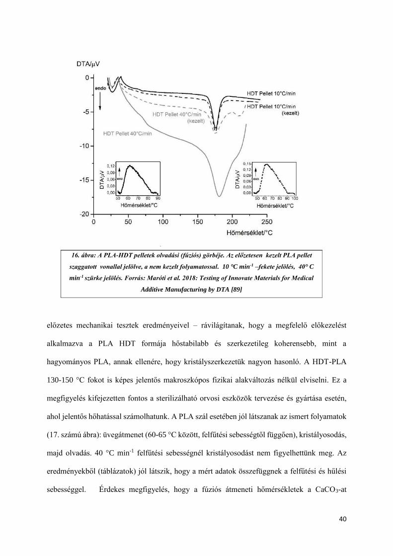
sebességen, összevetve a kezeletlen mintával. A PLA-HDT esetében a Tg értéke szintén
magasabb volt a kezeletlen esetben, összevetve a hagyományos PLA-val, körülbelül 8 °C-al, az
endoterm görbék csúcsa pedig körülbelül 25 °C-al magasabban helyezkedik el mindkét felfűtési
sebesség esetében (16. számú ábra és II. számú táblázat). A mért adatok – kiegészítve az
15. ábra: Felfűtési és hűlési görbék. Az előzetesen kezelt PLA pellet szaggatott vonallal
jelölve, a nem kezelt folyamatossal. 10 °C min-1 –fekete jelölés, 40° C min-1 szürke
jelölés. Forrás: Maróti et al. 2018: Testing of Innovate Materials for Medical Additive
Manufacturing by DTA [89]
40
előzetes mechanikai tesztek eredményeivel – rávilágítanak, hogy a megfelelő előkezelést
alkalmazva a PLA HDT formája hőstabilabb és szerkezetileg koherensebb, mint a
hagyományos PLA, annak ellenére, hogy kristályszerkezetük nagyon hasonló. A HDT-PLA
130-150 °C fokot is képes jelentős makroszkópos fizikai alakváltozás nélkül elviselni. Ez a
megfigyelés kifejezetten fontos a sterilizálható orvosi eszközök tervezése és gyártása esetén,
ahol jelentős hőhatással számolhatunk. A PLA szál esetében jól látszanak az ismert folyamatok
(17. számú ábra): üvegátmenet (60-65 °C között, felfűtési sebességtől függően), kristályosodás,
majd olvadás. 40 °C min-1 felfűtési sebességnél kristályosodást nem figyelhettünk meg. Az
eredményekből (táblázatok) jól látszik, hogy a mért adatok összefüggnek a felfűtési és hűlési
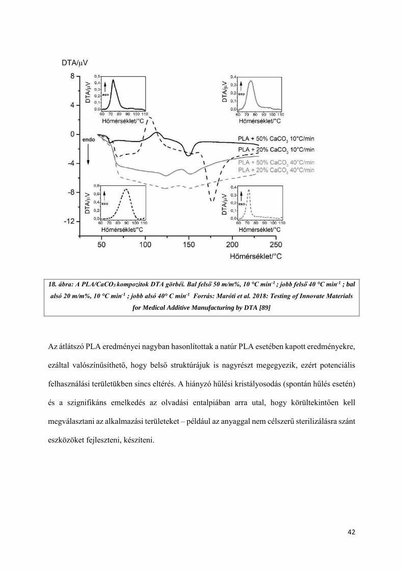
sebességgel. Érdekes megfigyelés, hogy a fúziós átmeneti hőmérsékletek a CaCO3-at
16. ábra: A PLA-HDT pelletek olvadási (fúziós) görbéje. Az előzetesen kezelt PLA pellet
szaggatott vonallal jelölve, a nem kezelt folyamatossal. 10 °C min-1 –fekete jelölés, 40° C
min-1 szürke jelölés. Forrás: Maróti et al. 2018: Testing of Innovate Materials for Medical
Additive Manufacturing by DTA [89]
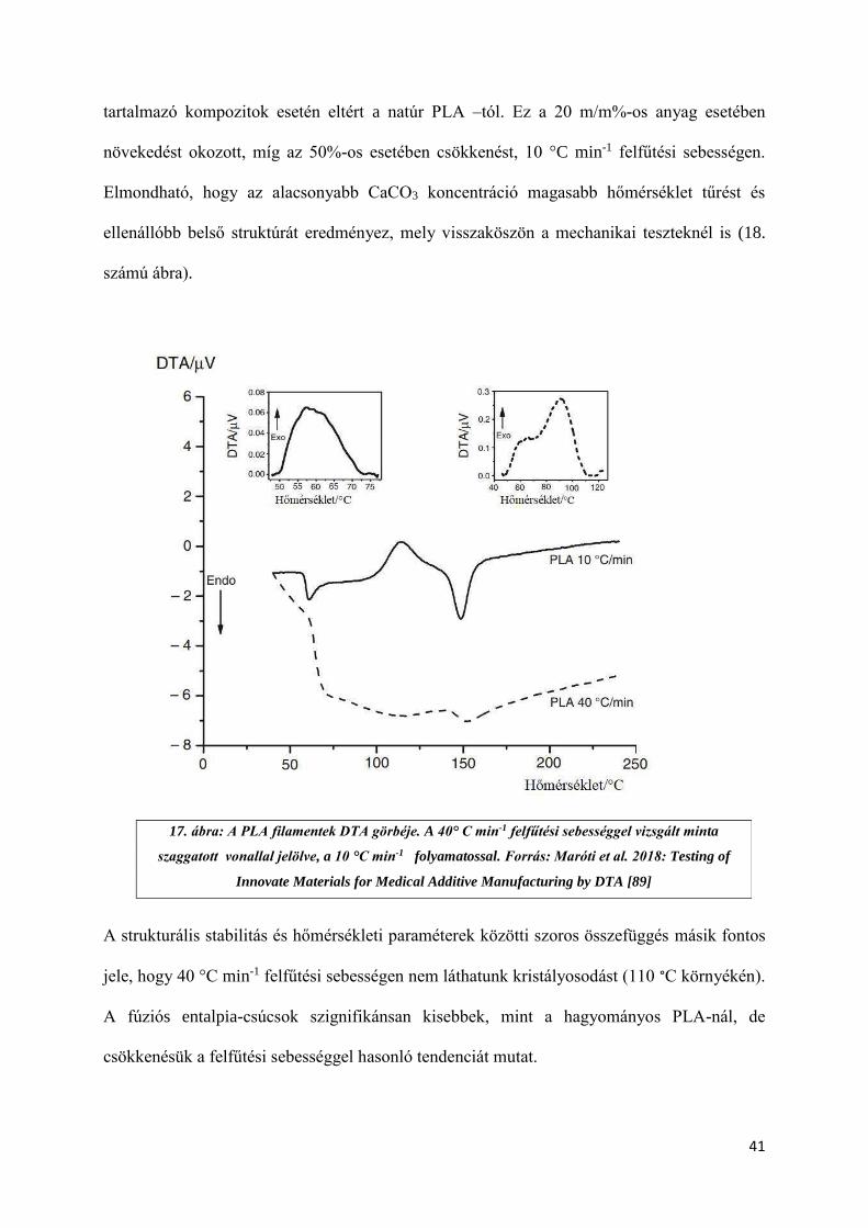
41
tartalmazó kompozitok esetén eltért a natúr PLA –tól. Ez a 20 m/m%-os anyag esetében
növekedést okozott, míg az 50%-os esetében csökkenést, 10 °C min-1 felfűtési sebességen.
Elmondható, hogy az alacsonyabb CaCO3 koncentráció magasabb hőmérséklet tűrést és
ellenállóbb belső struktúrát eredményez, mely visszaköszön a mechanikai teszteknél is (18.
számú ábra).
A strukturális stabilitás és hőmérsékleti paraméterek közötti szoros összefüggés másik fontos
jele, hogy 40 °C min-1 felfűtési sebességen nem láthatunk kristályosodást (110 °C környékén).
A fúziós entalpia-csúcsok szignifikánsan kisebbek, mint a hagyományos PLA-nál, de
csökkenésük a felfűtési sebességgel hasonló tendenciát mutat.
17. ábra: A PLA filamentek DTA görbéje. A 40° C min-1 felfűtési sebességgel vizsgált minta
szaggatott vonallal jelölve, a 10 °C min-1 folyamatossal. Forrás: Maróti et al. 2018: Testing of
Innovate Materials for Medical Additive Manufacturing by DTA [89]
42
18. ábra: A PLA/CaCO3 kompozitok DTA görbéi. Bal felső 50 m/m%, 10 °C min-1 ; jobb felső 40 °C min-1 ; bal
alsó 20 m/m%, 10 °C min-1 ; jobb alsó 40° C min-1 Forrás: Maróti et al. 2018: Testing of Innovate Materials
for Medical Additive Manufacturing by DTA [89]
Az átlátszó PLA eredményei nagyban hasonlítottak a natúr PLA esetében kapott eredményekre,
ezáltal valószínűsíthető, hogy belső struktúrájuk is nagyrészt megegyezik, ezért potenciális
felhasználási területükben sincs eltérés. A hiányzó hűlési kristályosodás (spontán hűlés esetén)
és a szignifikáns emelkedés az olvadási entalpiában arra utal, hogy körültekintően kell
megválasztani az alkalmazási területeket – például az anyaggal nem célszerű sterilizálásra szánt
eszközöket fejleszteni, készíteni.
43
1. táblázat: Entalpia értékek a vizsgált PLA minták fűtési és hűlési ciklusai során. Forrás: Maróti et
al. 2018: Testing of Innovate Materials for Medical Additive Manufacturing by DTA [89]
2. táblázat: Termikus analízis eredményei a vizsgálat PLA minták esetében, felfűtési és hűtési ciklusok
során. (Ton:: vizsgálat kezdete, Tend: vizsgálat vége. Tg: üvegesedési hőmérséklet, Thc: kristályosodás felfűtésnél,
Tcc: kristályosodás hűlésnél.) Forrás: Maróti et al. 2018: Testing of Innovate Materials for Medical Additive
Manufacturing by DTA [89]
44
4.2) Statikus és dinamikus mechanikai vizsgálatok eredményei
4.2.1) Statikus anyagtani mérések:
A statikus mérések eredményei alapján jól látszik, hogy az SLS technológiát használva nincs
szignifikáns eltérés a különböző nyomtatási orientációk értékei között. A három pontos
hajlítóvizsgálat elvégzése során X nyomtatási irányban 40,5 ± 1,5 MPa értéket kaptunk, míg Y
esetében 45,3 ± 1,2 MPa-t, Y esetében pedig 40,1 ± 1,9 MPa-t [90]. A többi technológia és
anyag esetén jelentős különbségeket láthatunk az egyes orientációk között. Az FDM™ és
PolyJet™ esetében ez szembetűnő az Z irány esetében, ahol szignifikánsabban kisebb
eredményeket mértünk, összevetve a többi iránnyal. Az anyagok összehasonlítása során
megfigyelhettük, hogy a PolyJet™ technológia alapanyagainak (Vero Grey™ és Digital ABS)
eredményei között nincs számottevő eltérés orientációnként. Az ipari FDM™ technológiát
használva az összes alapanyag és felbontás közül minden esetben az Y orientációban nyomtatott
próbatestek határhajlító feszültség értékei a legmagasabbak, 53,6 ± 2,2 MPa 0,178-mmel
nyomtatott ABS próbatestek esetében, míg az érték 57,6 ± 1.9 MPa volt 0,330 mm-es
felbontással. Az ULTEM™ kimagasló, 86,6 ± 0,8 MPa-os eredményt mutatott (19. számú ábra)
A Shore D keménységmérés orientációfüggetlennek mutatkozott, és megegyezett a technikai
adatlapokon szereplő értékekkel, valamint irodalmi adatokkal.
45
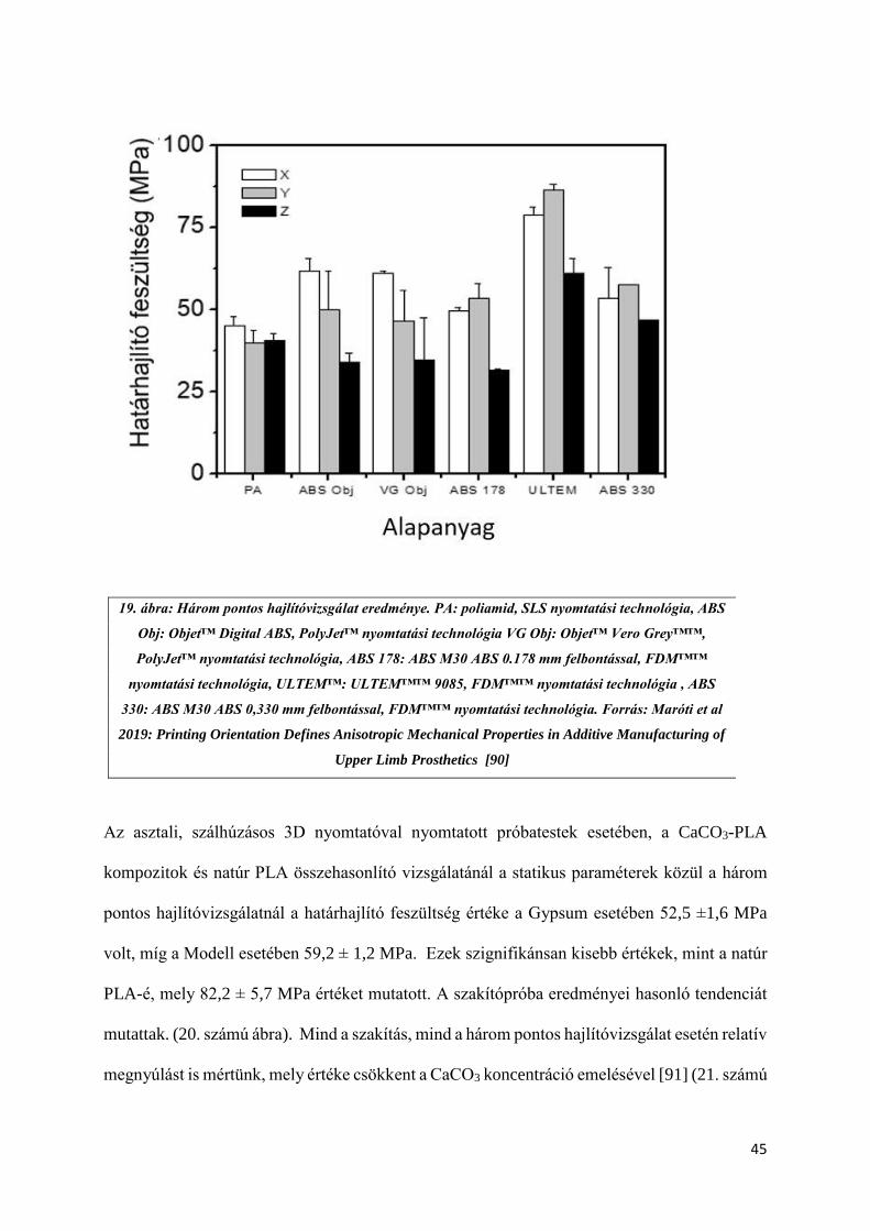
Az asztali, szálhúzásos 3D nyomtatóval nyomtatott próbatestek esetében, a CaCO3-PLA
kompozitok és natúr PLA összehasonlító vizsgálatánál a statikus paraméterek közül a három
pontos hajlítóvizsgálatnál a határhajlító feszültség értéke a Gypsum esetében 52,5 ±1,6 MPa
volt, míg a Modell esetében 59,2 ± 1,2 MPa. Ezek szignifikánsan kisebb értékek, mint a natúr
PLA-é, mely 82,2 ± 5,7 MPa értéket mutatott. A szakítópróba eredményei hasonló tendenciát
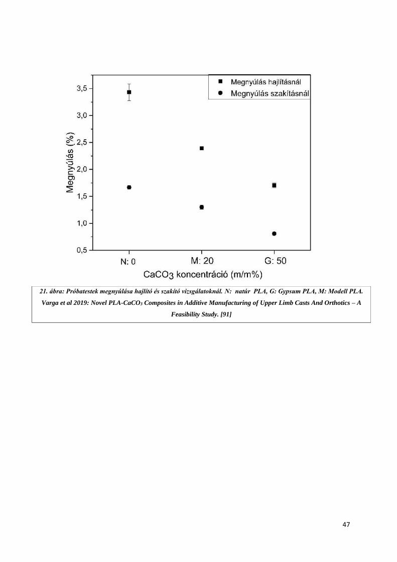
mutattak. (20. számú ábra). Mind a szakítás, mind a három pontos hajlítóvizsgálat esetén relatív
megnyúlást is mértünk, mely értéke csökkent a CaCO3 koncentráció emelésével [91] (21. számú
19. ábra: Három pontos hajlítóvizsgálat eredménye. PA: poliamid, SLS nyomtatási technológia, ABS
Obj: Objet™ Digital ABS, PolyJet™ nyomtatási technológia VG Obj: Objet™ Vero Grey™™,
PolyJet™ nyomtatási technológia, ABS 178: ABS M30 ABS 0.178 mm felbontással, FDM™™
nyomtatási technológia, ULTEM™: ULTEM™™ 9085, FDM™™ nyomtatási technológia , ABS
330: ABS M30 ABS 0,330 mm felbontással, FDM™™ nyomtatási technológia. Forrás: Maróti et al
2019: Printing Orientation Defines Anisotropic Mechanical Properties in Additive Manufacturing of
Upper Limb Prosthetics [90]
Alapanyag

46
ábra). A Shore D mérések eredményei között itt sem mértünk szignifikáns eltérést (77,0-77,9
értéket mutattak).
20. ábra: Statikus vizsgálatok eredményei PLA-CaCO3 kompozitok esetén N: natúr PLA, G:
Gypsum PLA, M: Modell PLA. Varga et al 2019: Novel PLA-CaCO3 Composites in Additive
Manufacturing of Upper Limb Casts And Orthotics – A Feasibility Study [91]
47
21. ábra: Próbatestek megnyúlása hajlító és szakító vizsgálatoknál. N: natúr PLA, G: Gypsum PLA, M: Modell PLA.
Varga et al 2019: Novel PLA-CaCO3 Composites in Additive Manufacturing of Upper Limb Casts And Orthotics – A
Feasibility Study. [91]

48
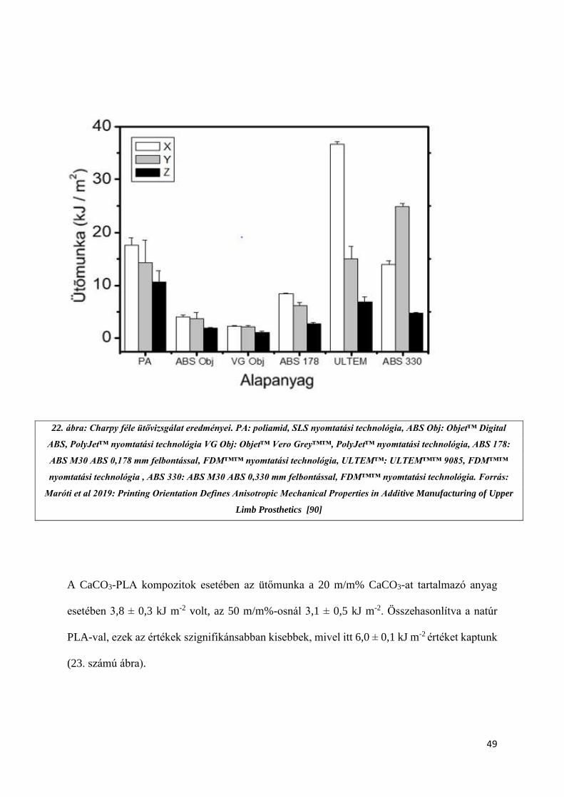
4.2.2) Dinamikus mérések eredményei:
A dinamikus mérések közül a Charpy ütővizsgálatot végeztük el. Hasonlóan a statikus mérések
esetében tapasztaltakhoz, a Z orientáció volt minden esetben a leggyengébb. Az ULTEM™
alapanyagnál kimagasló értéket láthatunk a X orientáció esetében (36,7 ± 0,5 kJ m-2). A
poliamid próbatestek mechanikai szempontból ellenállóbbnak bizonyultak minden esetben,
mint a PolyJet™ alapanyagai, melyeknél a legalacsonyabb értéket a Vero Grey™ mutatta, ez
2,3 ± 0,1 kJ m-2 volt X, 2,2 ± 0,2 kJ m-2 Y, és 1,2 ± 0,1 kJ m-2 Y orientációnál. (22. számú ábra).
Az SLS technológia eredményei a dinamikus teszt esetében is kisebb szórást mutattak, bár a Z
orientációnál mért érték szignifikánsabb kisebb volt, mint Y és X orientáció esetében. Érdekes
megfigyelés, hogy az ABS alapanyagok közül, melyet PolyJet™ és FDM™ technológiával is
előállítottunk, a legmagasabb értéket a 0,330 mm-el nyomtatott FDM™-es próbatesteknél
mérhettük, X orientációban, mely 24,9 ± 0,7 kJ m-2 volt. Ez az egyetlen eset a Charpy
ütővizsgálatoknál, ahol az Y irány magasabb értéket mutat, mint az X. Fontos megfigyelés,
hogy a dinamikus mérésnél a 0,330 mm-es rétegfelbontás erősebb struktúrát eredményez, mint
a finomabb, részletgazdagabb 0,178 mm-es.
49
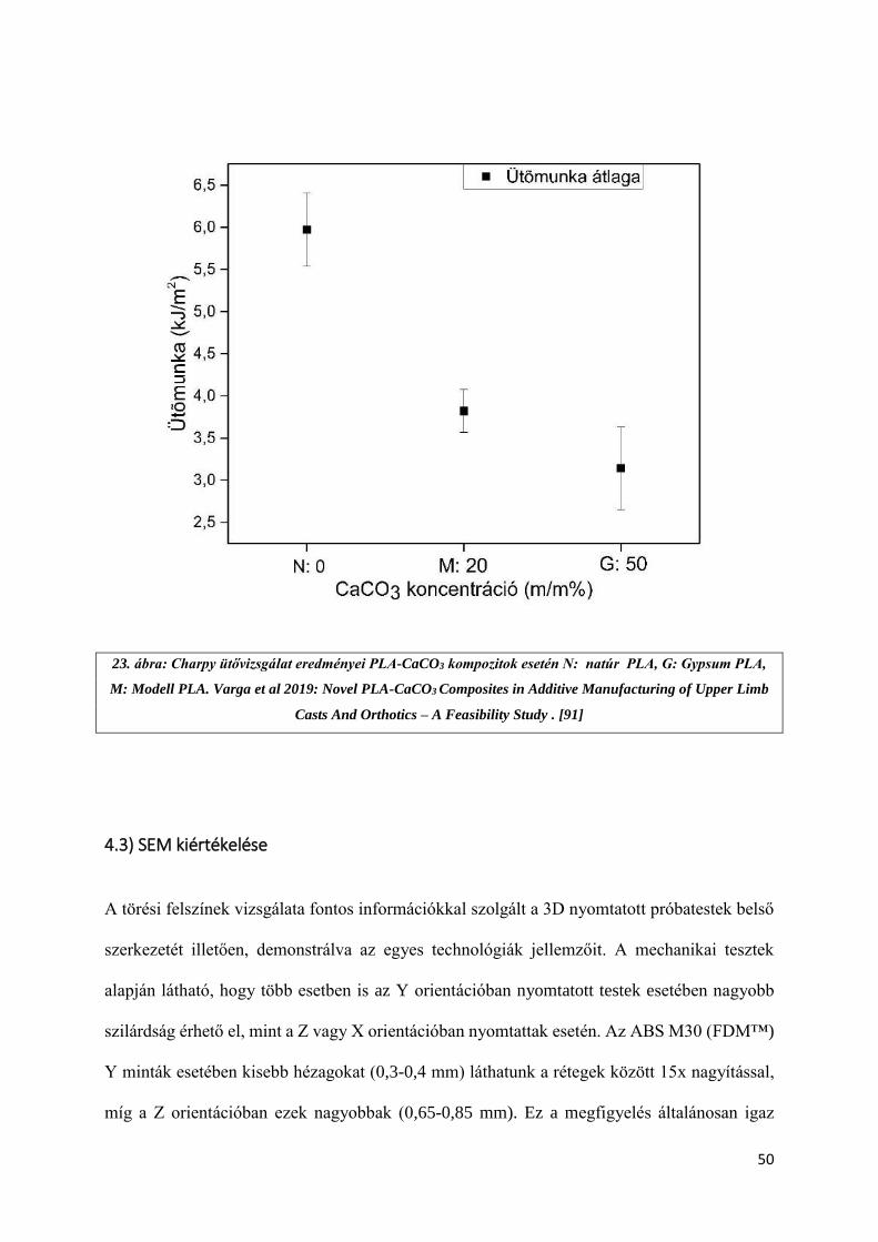
A CaCO3-PLA kompozitok esetében az ütőmunka a 20 m/m% CaCO3-at tartalmazó anyag
esetében 3,8 ± 0,3 kJ m-2 volt, az 50 m/m%-osnál 3,1 ± 0,5 kJ m-2. Összehasonlítva a natúr
PLA-val, ezek az értékek szignifikánsabban kisebbek, mivel itt 6,0 ± 0,1 kJ m-2 értéket kaptunk
(23. számú ábra).
22. ábra: Charpy féle ütővizsgálat eredményei. PA: poliamid, SLS nyomtatási technológia, ABS Obj: Objet™ Digital
ABS, PolyJet™ nyomtatási technológia VG Obj: Objet™ Vero Grey™™, PolyJet™ nyomtatási technológia, ABS 178:
ABS M30 ABS 0,178 mm felbontással, FDM™™ nyomtatási technológia, ULTEM™: ULTEM™™ 9085, FDM™™
nyomtatási technológia , ABS 330: ABS M30 ABS 0,330 mm felbontással, FDM™™ nyomtatási technológia. Forrás:
Maróti et al 2019: Printing Orientation Defines Anisotropic Mechanical Properties in Additive Manufacturing of Upper
Limb Prosthetics [90]
50
23. ábra: Charpy ütővizsgálat eredményei PLA-CaCO3 kompozitok esetén N: natúr PLA, G: Gypsum PLA,
M: Modell PLA. Varga et al 2019: Novel PLA-CaCO3 Composites in Additive Manufacturing of Upper Limb
Casts And Orthotics – A Feasibility Study . [91]
4.3) SEM kiértékelése
A törési felszínek vizsgálata fontos információkkal szolgált a 3D nyomtatott próbatestek belső
szerkezetét illetően, demonstrálva az egyes technológiák jellemzőit. A mechanikai tesztek
alapján látható, hogy több esetben is az Y orientációban nyomtatott testek esetében nagyobb
szilárdság érhető el, mint a Z vagy X orientációban nyomtattak esetén. Az ABS M30 (FDM™)
Y minták esetében kisebb hézagokat (0,3-0,4 mm) láthatunk a rétegek között 15x nagyítással,
míg a Z orientációban ezek nagyobbak (0,65-0,85 mm). Ez a megfigyelés általánosan igaz
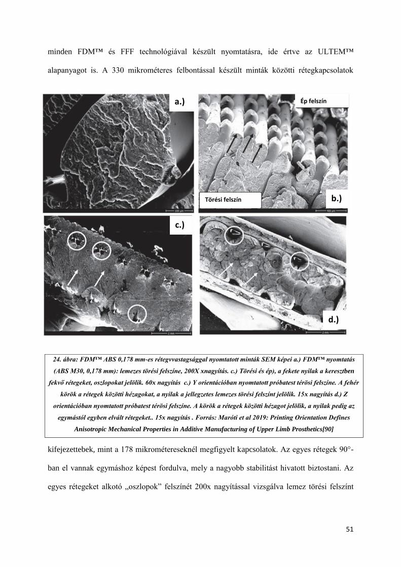
51
minden FDM™ és FFF technológiával készült nyomtatásra, ide értve az ULTEM™
alapanyagot is. A 330 mikrométeres felbontással készült minták közötti rétegkapcsolatok
kifejezettebek, mint a 178 mikrométereseknél megfigyelt kapcsolatok. Az egyes rétegek 90°-
ban el vannak egymáshoz képest fordulva, mely a nagyobb stabilitást hivatott biztostani. Az
egyes rétegeket alkotó „oszlopok” felszínét 200x nagyítással vizsgálva lemez törési felszínt
24. ábra: FDM™ ABS 0,178 mm-es rétegvvastagsággal nyomtatott minták SEM képei a.) FDM™ nyomtatás
(ABS M30, 0,178 mm): lemezes törési felszíne, 200X xnagyítás. c.) Törési és ép), a fekete nyilak a keresztben
fekvő rétegeket, oszlopokat jelölik. 60x nagyítás c.) Y orientációban nyomtatott próbatest térösi felszíne. A fehér
körök a rétegek közötti hézagokat, a nyilak a jellegzetes lemezes törési felszínt jelölik. 15x nagyítás d.) Z
orientációban nyomtatott próbatest térösi felszíne. A körök a rétegek közötti hézagot jelölik, a nyilak pedig az
egymástól egyben elvált rétegeket.. 15x nagyítás . Forrás: Maróti et al 2019: Printing Orientation Defines
Anisotropic Mechanical Properties in Additive Manufacturing of Upper Limb Prosthetics[90]
a.)
b.)
c.)
d.)
Ép felszín
Törési felszín
52
figyelhetünk meg, illetve az „oszlopok” deformálódását, mely vélhetően az extrúderből történő
kifolyást követő hűlés eredménye (24. számú ábra).
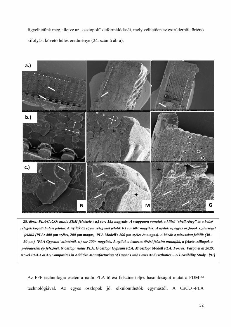
Az FFF technológia esetén a natúr PLA törési felszíne teljes hasonlóságot mutat a FDM™
technológiával. Az egyes oszlopok jól elkülöníthetők egymástól. A CaCO3-PLA
a.)
b.)
c.)
N M G
25. ábra: PLA/CaCO3 minta SEM felvétele : a.) sor: 15x nagyítás. A szaggatott vonalak a külső “shell réteg” és a belső
rétegek közötti határt jelölik. A nyilak az egyes rétegeket jelölik b.) sor 60x nagyítás: A nyilak az egyes oszlopok szélességét
jelölik (PLA: 400 μm széles, 200 μm magas, 'PLA Modell': 200 μm széles és magas). A körök a pórusokat jelölik (30–
50 μm) 'PLA Gypsum' mintánál. c.) sor 200× nagyítás. A nyilak a lemezes törési felszínt mutatják, a fekete csillagok a
próbatestek ép felszínét. N oszlop: natúr PLA, G oszlop: Gypsum PLA, M oszlop: Modell PLA. Forrás: Varga et al 2019:
Novel PLA-CaCO3 Composites in Additive Manufacturing of Upper Limb Casts And Orthotics – A Feasibility Study . [91]
53
kompozitoknál azonban jóval egységesebb, homogénebb struktúrát láthatunk. A PLA Modell
esetében az oszlopok jobban kivetők, vélhetően a megváltozott reológiai paramétereknek
köszönhetően, melyek a CaCO3 koncentrációval vannak összefüggésben. A Gypsum minták
esetében az oszlopos szerkezet eltűnik, helyette egy jóval porotikusabb felszínt láthatunk. A
pórusok mérete 30-50 mikrométeres nagyságrendbe esik. A kompozitok esetében a CaCO3
szemcsék is kivehetők (25. számú ábra). A szerkezet magyarázza az anyagok mechanikai
viselkedését.
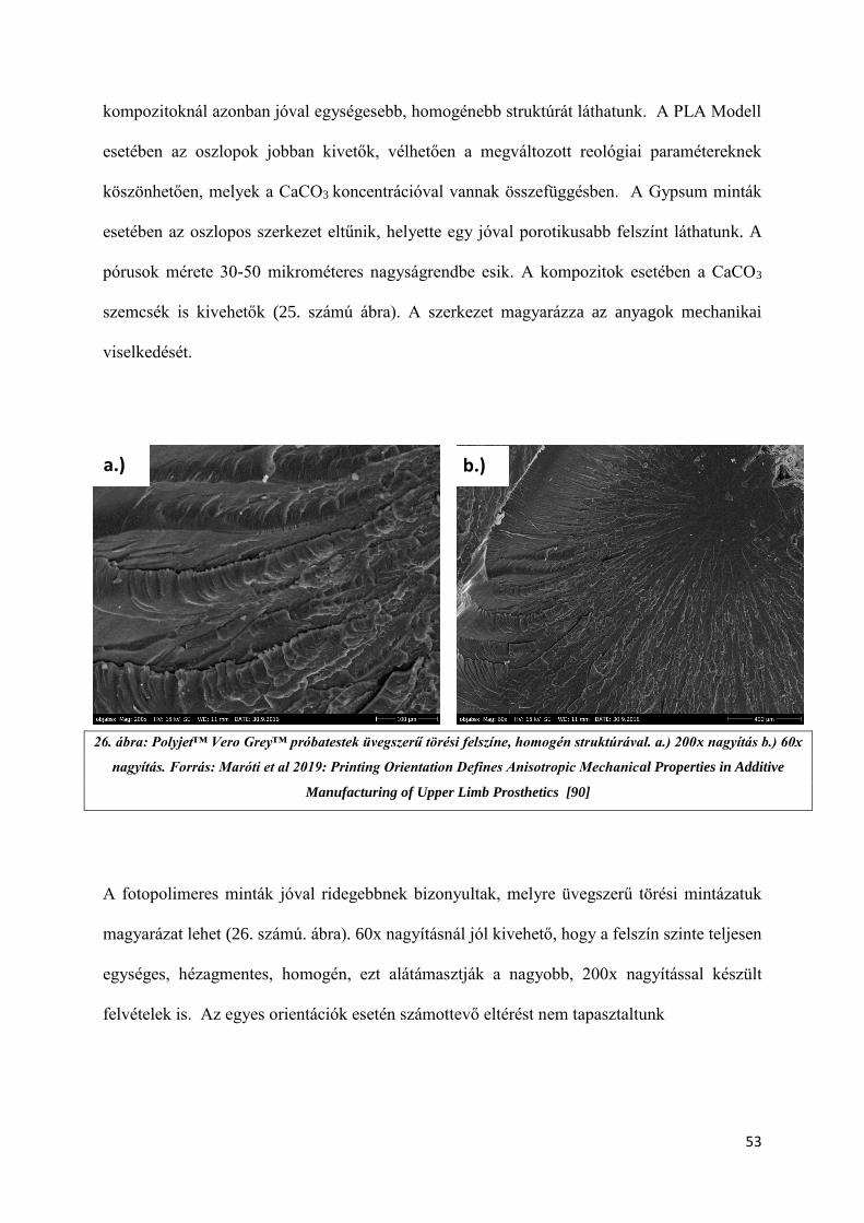
A fotopolimeres minták jóval ridegebbnek bizonyultak, melyre üvegszerű törési mintázatuk
magyarázat lehet (26. számú. ábra). 60x nagyításnál jól kivehető, hogy a felszín szinte teljesen
egységes, hézagmentes, homogén, ezt alátámasztják a nagyobb, 200x nagyítással készült
felvételek is. Az egyes orientációk esetén számottevő eltérést nem tapasztaltunk
26. ábra: Polyjet™ Vero Grey™ próbatestek üvegszerű törési felszíne, homogén struktúrával. a.) 200x nagyítás b.) 60x
nagyítás. Forrás: Maróti et al 2019: Printing Orientation Defines Anisotropic Mechanical Properties in Additive
Manufacturing of Upper Limb Prosthetics [90]
a.) b.)

54
A poliamid minták esetében, a lézerrel történő összeolvasztás miatt a belső szerkezet X,Y és Z
orientációban is megegyezik, mely összhangban van a mechanikai tesztek eredményével. Az
egyes rétegek között nem látható hézag, azonban az anyagra általánosságban porotikus
szerkekezet jellemző, ez jól kivehető 60x nagyítással (27. számú ábra).
27. ábra: SLS poliamid minták törési felszíne 60x nagyítással. a.) Y orientáció b.) X orientáció. A fehér körök a
pórusokat jelölik (30-80 µm). Saját felvétel.
a.) b.)
55
5.) Megbeszélés. Az eredmények gyakorlati hasznosíthatósága
5.1) 3D nyomtatással készült felső végtagi protézisek
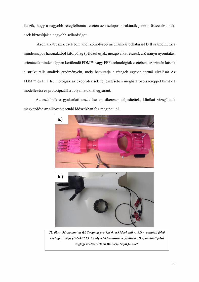
A vizsgálatban kapott eredményeket vettük alapul több, gyakorlatban használható eszköz
elkészítéséhez. Mechanikai méréseink eredményei alapján készítettünk el egy felső végtagi, 3D
nyomtatással készült, mechanikus protézis prototípusát, illetve egy myoelektromosan vezérelt,
két elektródás jelfelvétellel, és két darab lineáris aktuátorral működő eszközt is. A mechanikus
modell egy E-NABLE Raptor Reloaded és Phoenix hibridjeként jött létre, az E-NABLE
nemzetközi közösség által szolgáltatott modellek segítségével. (28. számú ábra). A mechanikus
modellnél találkoztunk azzal a jelenséggel, hogy a nyomtatási orientáció nagyban befolyásolja
az egyes munkadarabok stabilitását, mely mind az összeszerelés (például: csavarozás,
lemezelés), mind a mindennapi használat során fontos kérdés. A myoelektromosan vezérelt
modell az Open Bionics (https://openbionics.com/) vázszerkezetét használta fel, mely egy open
source CAD modell. Az elektronikai tervezést és összeszerelést kutatócsoportunk végezte. A
gyártáshoz asztali Craftbot 2 FFF nyomtatót vettünk igénybe. A 3D nyomtatás során PLA és
ABS alapanyagot egyaránt felhasználtunk, a myoelektromosan vezérelt eszköz esetén pedig
speciális, rugalmas PLA-kompozitot is, melyből a palmaris rész és az ujjak készültek el (29.
számú ábra). A nyomtatási orientációnál minden esetben törekedtünk – kapott eredményeinkre
való tekintettel - az „X” illetve „Y” irány menti nyomtatásra, illetve a nagyobb mechanikai
igénybevételnek kitett alkatrészek (burkolati elemek, tok) nagyobb rétegvastagságot
alkalmaztunk (200 vagy 300 mikrométer). Méréseink bebizonyították, hogy a nagyobb
rétegvastagság mechanikailag ellenállóbb struktúrát eredményez, ezért abban esetben, ha nem
szükséges a finom részletek kidolgozása, illetve fontos szempont az időhatékonyság, célszerű
lehet magasabb Z irányú felbontást alkalmazni. Ilyen alkatrészek lehetnek a külső borító elemek
vagy a tok. Ezen megfigyelésünket támasztották alá SEM-el készült felvételeink is, ahol jól
56
látszik, hogy a nagyobb rétegfelbontás esetén az oszlopos struktúrák jobban összeolvadnak,
ezek biztosítják a nagyobb szilárdságot.
Azon alkatrészek esetében, ahol komolyabb mechanikai behatással kell számolnunk a
mindennapos használatból kifolyólag (például ujjak, mozgó alkatrészek), a Z irányú nyomtatási
orientáció mindenképpen kerülendő FDM™ vagy FFF technológiák esetében, ez szintén látszik
a strukturális analízis eredményein, mely bemutatja a rétegek egyben törtnő elválását Az
FDM™ és FFF technológiák az exoprotézisek fejlesztésében meghatározó szereppel bírnak a
modellezési és prototípizálási folyamatoknál egyaránt.
Az eszközök a gyakorlati teszteléseken sikeresen teljesítettek, klinikai vizsgálatuk
megkezdése az elkövetkezendő időszakban fog megindulni.
28. ábra: 3D nyomatott felső végtagi protézisek. a.) Mechanikus 3D nyomtatott felső
végtagi protézis (E-NABLE). b.) Myoelektromosan vezérelhető 3D nyomtatott felső
végtagi protézis (Open Bionics). Saját felvétel.
a.)
b.)
57
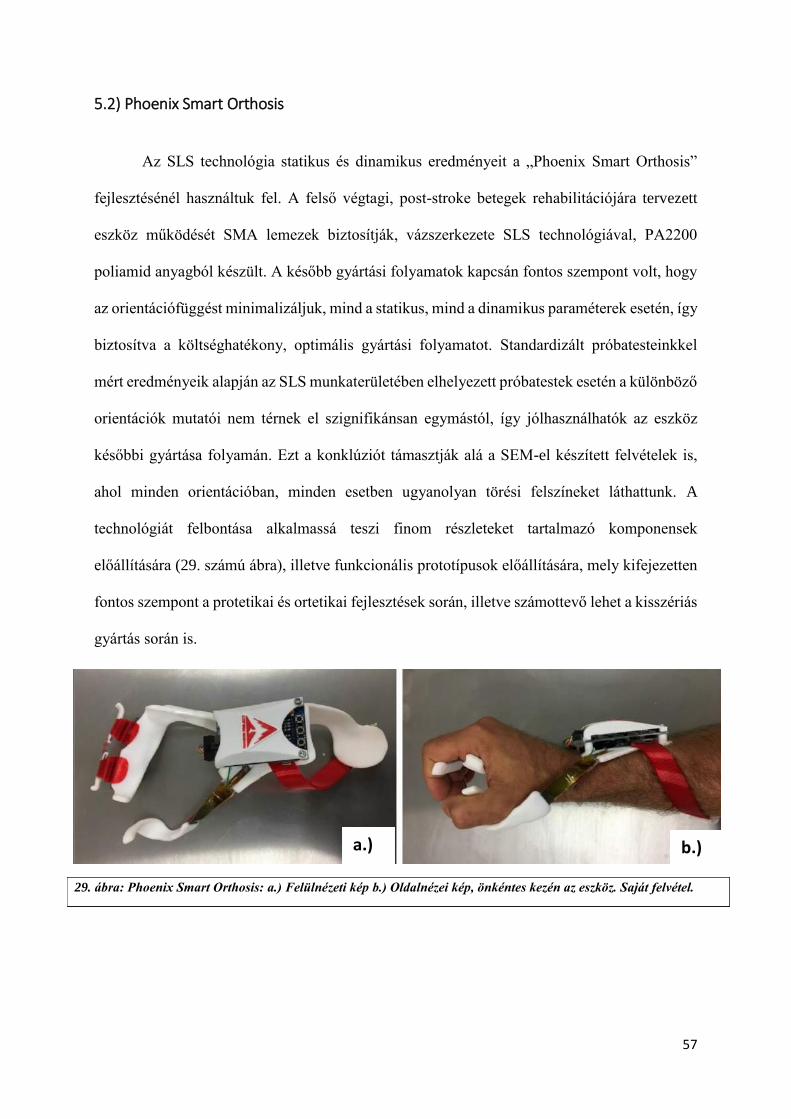
5.2) Phoenix Smart Orthosis
Az SLS technológia statikus és dinamikus eredményeit a „Phoenix Smart Orthosis”
fejlesztésénél használtuk fel. A felső végtagi, post-stroke betegek rehabilitációjára tervezett
eszköz működését SMA lemezek biztosítják, vázszerkezete SLS technológiával, PA2200
poliamid anyagból készült. A később gyártási folyamatok kapcsán fontos szempont volt, hogy
az orientációfüggést minimalizáljuk, mind a statikus, mind a dinamikus paraméterek esetén, így
biztosítva a költséghatékony, optimális gyártási folyamatot. Standardizált próbatesteinkkel
mért eredményeik alapján az SLS munkaterületében elhelyezett próbatestek esetén a különböző
orientációk mutatói nem térnek el szignifikánsan egymástól, így jólhasználhatók az eszköz
későbbi gyártása folyamán. Ezt a konklúziót támasztják alá a SEM-el készített felvételek is,
ahol minden orientációban, minden esetben ugyanolyan törési felszíneket láthattunk. A
technológiát felbontása alkalmassá teszi finom részleteket tartalmazó komponensek
előállítására (29. számú ábra), illetve funkcionális prototípusok előállítására, mely kifejezetten
fontos szempont a protetikai és ortetikai fejlesztések során, illetve számottevő lehet a kisszériás
gyártás során is.
29. ábra: Phoenix Smart Orthosis: a.) Felülnézeti kép b.) Oldalnézei kép, önkéntes kezén az eszköz. Saját felvétel.
a.) b.)
58
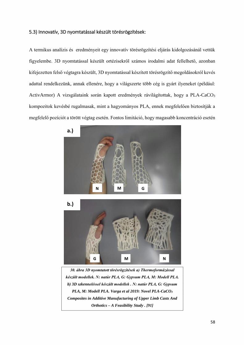
5.3) Innovatív, 3D nyomtatással készült törésrögzítések:
A termikus analízis és eredményeit egy innovatív törésrögzítési eljárás kidolgozásánál vettük
figyelembe. 3D nyomtatással készült ortézisekről számos irodalmi adat fellelhető, azonban
kifejezetten felső végtagra készült, 3D nyomtatással készített törésrögzítő megoldásokról kevés
adattal rendelkezünk, annak ellenére, hogy a világszerte több cég is gyárt ilyeneket (például:
ActivArmor) A vizsgálataink során kapott eredmények rávilágítottak, hogy a PLA-CaCO3
kompozitok kevésbé rugalmasak, mint a hagyományos PLA, ennek megfelelően biztosítják a
megfelelő pozíciót a törött végtag esetén. Fontos limitáció, hogy magasabb koncentráció esetén
30. ábra 3D nyomtatott törésrögzítések a) Thermoformázással
készült modellek. N: natúr PLA, G: Gypsum PLA, M: Modell PLA.
b) 3D szkenneléssel készült modellek . N: natúr PLA, G: Gypsum
PLA, M: Modell PLA. Varga et al 2019: Novel PLA-CaCO3
Composites in Additive Manufacturing of Upper Limb Casts And
Orthotics – A Feasibility Study . [91]
b.)
N
N G
G
M
M
a.)
b.)
59
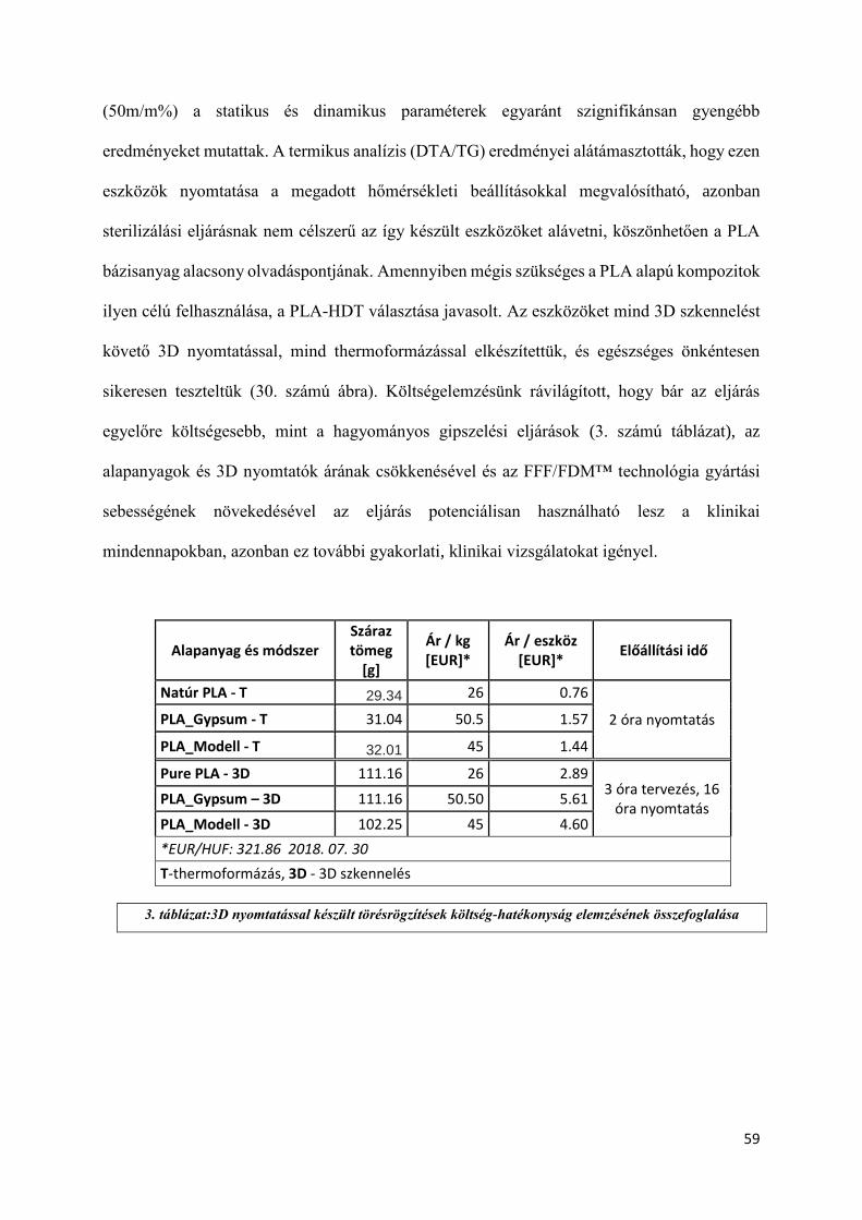
(50m/m%) a statikus és dinamikus paraméterek egyaránt szignifikánsan gyengébb
eredményeket mutattak. A termikus analízis (DTA/TG) eredményei alátámasztották, hogy ezen
eszközök nyomtatása a megadott hőmérsékleti beállításokkal megvalósítható, azonban
sterilizálási eljárásnak nem célszerű az így készült eszközöket alávetni, köszönhetően a PLA
bázisanyag alacsony olvadáspontjának. Amennyiben mégis szükséges a PLA alapú kompozitok
ilyen célú felhasználása, a PLA-HDT választása javasolt. Az eszközöket mind 3D szkennelést
követő 3D nyomtatással, mind thermoformázással elkészítettük, és egészséges önkéntesen
sikeresen teszteltük (30. számú ábra). Költségelemzésünk rávilágított, hogy bár az eljárás
egyelőre költségesebb, mint a hagyományos gipszelési eljárások (3. számú táblázat), az
alapanyagok és 3D nyomtatók árának csökkenésével és az FFF/FDM™ technológia gyártási
sebességének növekedésével az eljárás potenciálisan használható lesz a klinikai
mindennapokban, azonban ez további gyakorlati, klinikai vizsgálatokat igényel.
Alapanyag és módszer Száraz tömeg
[g]
Ár / kg [EUR]*
Ár / eszköz [EUR]*
Előállítási idő
Natúr PLA - T 29.34 26 0.76
2 óra nyomtatás PLA_Gypsum - T 31.04 50.5 1.57
PLA_Modell - T 32.01 45 1.44
Pure PLA - 3D 111.16 26 2.89 3 óra tervezés, 16
óra nyomtatás PLA_Gypsum – 3D 111.16 50.50 5.61
PLA_Modell - 3D 102.25 45 4.60
*EUR/HUF: 321.86 2018. 07. 30
T-thermoformázás, 3D - 3D szkennelés
3. táblázat:3D nyomtatással készült törésrögzítések költség-hatékonyság elemzésének összefoglalása
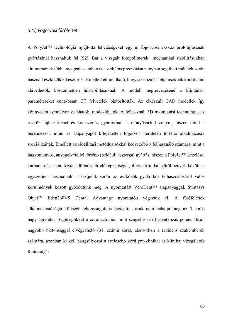
60
5.4.) Fogorvosi fúrófeltét:
A PolyJet™ technológia nyújtotta lehetőségeket egy új fogorvosi eszköz prototípusának
gyártásánál használtuk fel [92]. Bár a vizsgált fotopolimerek mechanikai stabilitásukban
alulmaradnak több anyaggal szemben is, az eljárás precizitása nagyban segítheti műtétek során
használt eszközök elkészítését. Emellett elmondható, hogy sterilizálási eljárásoknak korlátlanul
alávethetők, köszönhetően hőstabilitásuknak. A modell megtervezésénél a kiindulási
paramétereket cone-beam CT felvételek biztosították. Az elkészült CAD modellek így
könnyedén személyre szabhatók, módosíthatók. A felhasznált 3D nyomtatási technológia az
eszköz fejlesztésénél és kis szériás gyártásánál is előnyösnek bizonyul, hiszen mind a
berendezést, mind az alapanyagot kifejezetten fogorvosi területen történő alkalmazásra
specializálták. Emellett az előállítási metódus sokkal kedvezőbb a felhasználó számára, mint a
hagyományos, anyagelvétellel történő (például: eszterga) gyártás, hiszen a PolyJet™ kezelése,
karbantartása nem kíván különösebb előképzettséget, illetve klinikai körülmények között is
egyszerűen használható. Tesztjeink során az eszközök gyakorlati felhasználásáról valós
körülmények között győződtünk meg. A nyomtatást VeroDent™ alapanyaggal, Stratasys
Objet™ Eden260VS Dental Advantage nyomtatón végeztük el. A fúrófeltétek
alkalmazhatóságát költséghatékonyságuk is biztosítja, áruk nem haladja meg az 5 eurós
nagyságrendet. Segítségükkel a coronectomia, mint szájsebészeti beavatkozás potenciálisan
nagyobb biztonsággal elvégezhető (31. számú ábra), elsősorban a rezidens szakemberek
számára, azonban ki kell hangsúlyozni a szélesebb körű pre-klinikai és klinikai vizsgálatok
fontosságát.
61
31. ábra: Fogorvosi fúrófeltét a.) Fogorvosi fúrófeltét méretének visszaellenőrzése tolómérővel. b.) Fogorvosi
fúrótfeltét használat közben. Forrás: Szalma et al. 2018: Three-Dimensionally Printed Individual Drill Sleeve
for Depth-Controlled Sections in Third Molar Surgery [92]

62
6.) Eredmények összefoglalása
Vizsgálatsorozatunk lehetővé tette az orvostechnológiai fejlesztésekben leggyakrabban
használt additív gyártástechnológiai eljárások részletes és objektív jellemzést
anyagtechnológiai szempontból, illetve fontos gyakorlati kérdések megválaszolására is
lehetőségünk nyílt. A korábban, nemzetközi szinten publikált tanulmányok adatainak és saját
eredményeink tükrében elmondható, hogy az FDM™, FFF, SLS és PolyJet™ technológiák
külön-külön és kombináltan is alkalmasak orvosi eszközök, gyógyászati segédeszközök
fejlesztésére, kis szériás gyártására. Az irodalomi adatokra alapozva kutatócsoportunk is
megállapította az egyes nyomtatási eljárások orientációfüggését, kiterjesztve a vizsgálatokat
statikus és dinamikus módszerekre is, illetve az egyes eljárások egymáshoz való viszonyítását
is sikeresen elvégezte. A mechanikai tesztek kiegészítése pásztázó elektron mikroszkópos
vizsgálatokkal csak részben valósult meg a nemzetközi szinten publikált tanulmányokban.
CaCO3-t tartalmazó, 3D nyomtatásra szánt kompozitok termoanalitikai vizsgálatát korábban egy
kutatócsoport sem végezte el, ahogy a vizsgált anyagokat sem jellemezték gyakorlati
felhasználás szempontjából (például: költséghatékonysági elemzés, gyárthatóság, pre-klinikai
vizsgálatok), annak ellenére, hogy több publikáció is elérhető 3D nyomtatott felső végtagi
protézisek, orthézisek fejlesztéséről, valamint fogorvosi alkalmazásokról egyaránt.
Kutatásunk eredményei alapján az alábbi főbb megállapításokat tehetjük az általunk vizsgált,
orvosi eszközfejlesztésben használható, polimerekkel és kompozitokkal dolgozó additív
gyártástechnológiai megoldásokról:
6.1) Gyakorlati felhasználhatóság:
Az FDM™, FFF, SLS és PolyJet™ technológiák mindegyike sikeresen felhasználható
az orvosi eszközfejlesztésben, köszönhetően a viszonylag széles alapanyag-

63
választéknak, az ebből fakadó széles spektrumú mechanikai, termikus és szerkezeti
jellemzőknek.
Vizsgálataink során nemzetközi szinten első alkalommal készítettünk komplex, átfogó
orvosi eszközfejlesztésben érintett anyagtechnológiai vizsgálatot több additív
gyártástechnológiai megoldást is bevonva, gyakorlati problémákon keresztülvezetve
Vizsgálatunk során több új orvostechnológiai termék, segédeszköz született meg
(Phoenix Smart Orthosis, fogorvosi fúrófeltét).
A vizsgált technológiák a kezdeti modellgyártásban, termék/ötlet vizualizációban,
prototípus-gyártásban és kis szériás gyártásban egyaránt használhatók. Az FFF
technológia elsősorban a modellezésben és a korai fázisú prototípus-gyártásban
előnyös, FDM™ technológiával ipari alapanyagokat használva (pl.: ULTEM™) kis
szériás gyártás is megvalósítható. Az SLS előnyei a funkcionális prototípus-gyártásban
és kis szériás gyártásban mutatkoznak meg elsősorban, míg a PolyJet™ a nagyon
részletes, finom struktúrák kialakításában előnyös.
Az elkészített és gyakorlatban készített eszközök mindegyike potenciálisan használható
az egészségügyi felsőoktatásban vagy a klinikai gyakorlatban. A megkezdett
fejlesztések klinikai tesztelése megkezdődhet a közeljövőben, a megfelelő etikai
engedélyek birtokában, hiszen gyakorlati kipróbálásuk sikeresen megtörtént.
6.2) Anyagtechnológiai és gyártástechnológiai jellemzők:
Szálhúzásos (FDM™ és FFF) technológiák esetén mind a statikus, mind a dinamikus
paraméterek esetén kedvezőbb az X és Y orientáció alkalmazása, ez általános
megállapítás minden orvosi eszköz és segédeszköz fejlesztése során. Egyes alkatrészek,
64
modellek, melyek nyomtatása csak Z orientációban tud megtörténni és ipari
technológiák használatát igényelhetik (pl.: SLS vagy FDM™ ULTEM™ alapanyaggal).
Kutatócsoportunk elsőként tesztelte mechanikai és termoanalitikai szempontból a 3D
nyomtatásban használható PLA-CaCO3 kompozitokat (PLA Modell, PLA Gypsum).
A nagyobb rétegfelbontás erősebb belső struktúrát eredményez, ezáltal mechanikailag
stabilabb munkadarabot kapunk, hatékonyabb gyártási folyamatok mellett (idő,
költséghatékonyság), mely a protézisfejlesztésben és gyártásban egyaránt fontos
szempont.
Adalékanyagok – esetünkben CaCO3 – hozzáadása a thermoplasztikus polimer
bázisanyaghoz nagyban befolyásolja a statikus és dinamikus mechanikai paramétereket.
A törésrögzítések esetén ez kisebb rugalmasságot, megnyúlást jelent, ezáltal
potenciálisan hatékonyak lehetnek a felső végtagi törések fixálásában, és páciens-barát
felhasználásában.
A termikus analízis eredményei rávilágítottak, hogy a vizsgált PLA-CaCO3 kompozitok
potenciálisan alkalmazhatók törésrögzítések előállítására, illetve a HDT PLA
kifejezetten alkalmas hősterilezési eljárásokkal készült eszközök fejlesztésére. A
strukturális vizsgálatok is ezt támasztották alá.
Elmondható, hogy a Shore D keménység, mint statikus paraméter, a nyomtatási
orientációtól független.
A költséghatékonysági elemzések a törésrögzítések és a fogorvosi fúrófeltétek esetében
rávilágítottak, hogy a technológia viszonylag rövid időn belül alkalmazható lehet a napi
szintű klinikai tevékenységben.
Komplex eszközök (például: végtagprotézisek) előállítása során több eltérő technológia
és/vagy nyomtatási paraméter együttes alkalmazása lehet javasolt, az egyes alkatrészek
mechanikai igénybevételének és a funkcionalitásnak figyelembevételével.
65
7.) Saját közlemények, konferenciarészvételek listája:
7.1) A dolgozat alapjául szolgáló közlemények listája
1.) P. Maróti, P. Varga, A. Ferencz, Z. Ujfalusi, M. Nyitrai, D. Lőrinczy, Testing of
innovative materials for medical additive manufacturing by DTA, Journal of Thermal
Analysis and Calorimetry 2019;136:2041-48
DOI: https://doi.org/10.1007/s10973-018-7839-x
2.) P. Maroti, P. Varga, H. Abraham, G. Falk, T. Zsebe, Z. Meiszterics, S. Mano, Z.
Csernatony, S. Rendeki, M. Nyitrai, Printing orientation defines anisotropic
mechanical properties in additive manufacturing of upper limb prosthetics, Materials
Research Expres (2019)
DOI: https://doi.org/10.1088/2053-1591/aaf5a9
3.) J. Szalma, B.V. Lovász, E. Lempel, P. Maróti, Three-Dimensionally Printed
Individual Drill Sleeve for Depth-Controlled Sections Third Molar Surgery, Journal of
Oral and Maxillofacial Surgery (2018)
DOI: https://doi.org/10.1016/j.joms.2018.11.028
4.) P. Varga, D. Lorinczy, L. Toth, A. Pentek, M. Nyitrai, P. Maroti, Novel PLA-CaCO3
composites in additive manufacturing of upper limb casts and orthotics—A feasibility
study, Materials Research Express 6(4) (2019) 045317
DOI: https://doi.org/10.1088/2053-1591/aafdbc

66
7.2) A dolgozat alapjául nem szolgáló saját közlemények és konferenciák:
7.2.1) Publikációk, poszterek:
1.) Horváth Orsolya, Maróti Péter
3D Nyomtatott fegyverek – Vélt vagy valós veszélyek?
PÉCSI HATÁRŐR TUDOMÁNYOS KÖZLEMÉNYEK 20. p. 73 (2018)
2.) Henter I, Figler M, Maróti P, Berényi K
A praxisközösségi működés tapasztalatai a dietetikus szemszögéből
NÉPEGÉSZSÉGÜGY 95 : 1 pp. 47-51. , 5 p. (2017)
3.) Keresztes Dóra, Woth Gábor, Nagy Bálint János, Farkas József, Németh Zsuzsanna,
Maróti Péter, Rendeki Mátyás, Rendeki Szilárd: Kárhelyszíni elsősegélynyújtás - a
disaster medic képzés első tapasztalatai tűzoltók körében: VédelemTudomány online
folyóírat II/1 2017.03
4.) An International Association for Medical Education (AMEE) Conference 2016,
Barcelona, Spain, - poster presentation: Adam Tibor Schlelg MD, Peter Varga MD,
Peter Maroti MD, Ian O’Sullivan MD, Csaba Vermes MD, Peter Than MD: Patient
specific 3D printed hip models for easier understanding the total hip arthroplasty in
developmental dsysplasia of the hip
5.) An International Association for Medical Education (AMEE) Conference 2015,
Glasgow -e poszter: Peter Maroti, Adam Tibor Schlegl MD, Peter Varga, Szilard
67
Rendeki MD: Multidisciplinary simulations to improve teamwork and medical skills
at the same time – e-poster presentation
6.) 3rd International Interdisciplinary 3D Conference: The Role of Additive
Manufacturing in Upper Limb Prosthetic Development V. Potári, A. Péntek, P. Varga,
M. Bene, D. Berki, Á. Árvai, P. Maróti, M. Nyitrai
7.2.2) Konferenciák:
1.) 1st International Interdisciplinary 3D Conference - alapító és főszervező, workshop
előadó – 2015
2.) 2nd International Interdisciplinary 3D Conference - főszervező, ISBN 978-963-429-
066-7 – 2016
3.) 3rd International Interdisciplinary 3D Conference - szervező ISBN 978-963-429-165-
7 – 2017
4.) 2nd International Interdisciplinary 3D Conference: The mechanical and structural
effects of printing orientation in 3D printed upper limb prosthetics: Péter Maróti ,János
Móczár, Péter Varga, Zoltán Meiszterics,Tamás Zsebe,Hajnalka Ábrahám, Miklós
Nyitrai
5.) 2nd International Interdisciplinary 3D Conference: Anastomosis Quality Analysis
Using 3D Technologies: B Gasz, P Varga and P Maróti
68
6.) PTE Grastyán Endre Szakkollégium VII. International and XIII. National
Interdisciplinary Conference – 2015- Maróti Péter, Schlégl Ádám Tibor, Varga Péter:
A simulation based method to improve medical skills in emergency situtations -
legjobb előadás díja
7.) PTE Grastyán Endre Szakkollégium VII. International and XIII. National
Interdisciplinary Conference – 2015 - Peter Maroti, Szilard Rendeki: A possible
reaction to CBRN threats, involving the Operational Medicine Concept
8.) NATO RWS 267 Advanced Medical Training Workshop, 2016, Romania, Bukarest -
Advanced Medical Technologies of Training" lecutre, Szilard Rendeki MD, Peter
Varga MD, Peter Maroti MD, Brief Introduction to Simulation Education in
Operational Medicine
9.) An International Association for Medical Education (AMEE) Conference 2016,
Barcelona, Spain, Patil Teaching In Innovation Award előadás - Peter Maroti MD,
Peter Varga MD, Miklos Nyitrai MD, Adam Tibor Schlegl MD, Robert Pilisi, Szilard
Rendeki MD: 3D Printing in Cost Effective Simulation Education – Intraosseus
Trainer – lecture
69
8.) Köszönetnyilvánítás
Ezúton szeretném megköszönni a támogatást Témavezetőimnek, Prof. Dr. Nyitrai
Miklós és Prof. Dr. Lőrinczy Dénes Professzor Uraknak. Köszönöm a rengeteg szakmai
útmutatást, segítséget, és a sok időt türelmet, amit rám szántak a publikációk és jelen
dolgozat elkészülése céljából. Nyitrai Professzor Urat külön köszönet és hála illeti meg
emberi, mentori – „szakmai apukai” – szerepvállalásáért, és azért, hogy a legnehezebb
pillanatokban sem engedte feladni, mindig kiváló tanácsokkal látott el. Emellett sose fogom
tudni eléggé megköszönni azt, hogy bízott bennem, és lehetőséget adott szakmai karrierem
kibontakozásának, és hogy igazi, hiteles példát állított számomra emberi, tudományos és
szakmai szinten egyaránt.
Külön köszönet illeti Dr. Rendeki Szilárdot, akire nem csak Mentorként, hanem
Barátként, „Bajtársként” is felnézhettem, és hogy közel 10 éve együtt küzdhetünk a közös
szakmai célkitűzéseinkért – mint a MediSkillsLab vagy a Műveleti Medicina Koncepció,
illetve azt, hogy elindított a megkezdett úton. Két mentoromnak köszönhetően bátran
kijelenthetem, hogy valóban „büszkeség és öröm” Karunkon dolgozni.
Köszönöm Édesanyámnak, Hajdu Teréziának és Testvéremnek, Dr. Sümegi Ágnesnek,
akik mindig támogatták, segítették szakmai előre haladásomat, és hálás vagyok, hogy egész
életemben, mindig számíthattam Rájuk. Bár már sajnos nincsen köztük, köszönet illeti
Édesapámat, Maróti Dezsőt, aki megalapozta a tanulmányaimhoz vezető utat és akitől a
munka tiszteletét, szeretetét megtanulhattam.
Köszönet illeti Páromat, Dr. Tóth Lucát – és családját-, aki az elmúlt években minden
szakmai és emberi helyzetben mellett állt és segített, támogatott, véget nem érő türelemmel.
Nélküle jelen dolgozat sem készülhetett volna el, melyet Neki ajánlok őszinte szeretettel.
70
Köszönöm a kutatásban nyújtott szakmai és emberi segítséget Péntek Attilának és Bene
Mátyásnak akik nem csak sok eredményhez, de rengeteg közös fejlesztéshez járultak hozzá,
emellett barátságukkal is megtiszteltek.
Köszönettel tartozom Barátaimnak is, akikre a hosszú évek és évtizedek alatt mindig
számíthattam: Erdei Dánielnek, Gregor Zsoltnak, Bíró Zsoltnak, Káldy Zsoltnak, Kulcsár
Ákosnak, Dr. Schlégl Ádámnak, Dr. Simán Benedeknek és Párjának, Dr. Fodor
Fruzsinának, Dr. Virág Márknak, Márovics Gergelynek, Zag Gábornak és Dr. Duga
Zsófiának.
Köszönöm Prof. Dr. Kiss Istvánnak, az Orvosi Népegészségtani Intézet Igazgatójának,
aki a rezidensképzési programomhoz nyújtott nélkülözhetetlen, óriási támogatást,
segítséget.
Köszönöm Csóka Csabának, a Corvus-Med Kft. ügyvezetőjének, aki nem csak
szakmailag támogatta kutatásaimat, hanem Barátként is.
Köszönettel tartozom Dr. Szalma Józsefnek, akivel közösen egy ígéretes kutatási
témába vághattam bele.
Köszönet illeti céges partnereinket is, akik jelentősen hozzájárultak a munka sikeres
elvégzéséhez: Gelanyi Innvovations Kft, Philamania Kft. és Varinex Zrt.
Továbbá hálámat szeretném kifejezni az Általános Orvostudományi Kar több szervezeti
egységének is: az Orvosi Népegészségtani Intézet, a Biofizikai Intézet, a Műveleti Medicina
Tanszék, a Szimulációs Oktatási Központ és PTE 3D Projekt minden Munkatársának
hálával tartozom.
A dolgozat elkészítéséhez nagyban hozzájárultak a GINOP-2.3.2-000022 és EFOP
3.6.1-16-2016-00004 kódjelű pályázatok.
71
9.) Felhasznált források:
[1] T. Rayna, L. Striukova, From rapid prototyping to home fabrication: How 3D printing is
changing business model innovation, Technological Forecasting and Social Change 102
(2016) 214-224.
[2] J.-Y. Lee, J. An, C.K. Chua, Fundamentals and applications of 3D printing for novel
materials, Applied Materials Today 7 (2017) 120-133.
[3] J.L. Hermsen, T.M. Burke, S.P. Seslar, D.S. Owens, B.A. Ripley, N.A. Mokadam, E.D.
Verrier, Scan, plan, print, practice, perform: Development and use of a patient-specific 3-
dimensional printed model in adult cardiac surgery, The Journal of Thoracic and
Cardiovascular Surgery 153(1) (2017) 132-140.
[4] J. Garcia, Z. Yang, R. Mongrain, R.L. Leask, K. Lachapelle, 3D printing materials and
their use in medical education: a review of current technology and trends for the future, BMJ
Simulation and Technology Enhanced Learning 4(1) (2018) 27.
[5] T.M. Bücking, E.R. Hill, J.L. Robertson, E. Maneas, A.A. Plumb, D.I. Nikitichev, From
medical imaging data to 3D printed anatomical models, PLOS ONE 12(5) (2017) e03540.
[6] J. Norman, R.D. Madurawe, C.M.V. Moore, M.A. Khan, A. Khairuzzaman, A new
chapter in pharmaceutical manufacturing: 3D-printed drug products, Advanced Drug Delivery
Reviews 108 (2017) 39-50.
[7] P. Tack, J. Victor, P. Gemmel, L. Annemans, 3D-printing techniques in a medical setting:
a systematic literature review, BioMedical Engineering OnLine 15(1) (2016) 115.
[8] A. Shafiee, A. Atala, Printing Technologies for Medical Applications, Trends in
Molecular Medicine 22(3) (2016) 254-265.
[9] M.H. Michalski, J.S. Ross, The shape of things to come: 3d printing in medicine, JAMA
312(21) (2014) 2213-2214.
72
[10] H.N. Chia, B.M. Wu, Recent advances in 3D printing of biomaterials, Journal of
Biological Engineering 9(1) (2015) 4.
[11] J.T. Cantrell, S. Rohde, D. Damiani, R. Gurnani, L. DiSandro, J. Anton, A. Young, A.
Jerez, D. Steinbach, C. Kroese, P.G. Ifju, Experimental characterization of the mechanical
properties of 3D-printed ABS and polycarbonate parts, Rapid Prototyping Journal 23(4)
(2017) 811-824.
[12] B.M. Tymrak, M. Kreiger, J.M. Pearce, Mechanical properties of components fabricated
with open-source 3-D printers under realistic environmental conditions, Materials & Design
58(Supplement C) (2014) 242-246.
[13] E. Macdonald, R. Salas, D. Espalin, M. Perez, E. Aguilera, D. Muse, R.B. Wicker, 3D
Printing for the Rapid Prototyping of Structural Electronics, IEEE Access 2 (2014) 234-242.
[14] C. Gosselin, R. Duballet, P. Roux, N. Gaudillière, J. Dirrenberger, P. Morel, Large-scale
3D printing of ultra-high performance concrete – a new processing route for architects and
builders, Materials & Design 100 (2016) 102-109.
[15] E. García-Tuñon, S. Barg, J. Franco, R. Bell, S. Eslava, E. D'Elia, R.C. Maher, F.
Guitian, E. Saiz, Printing in Three Dimensions with Graphene, Advanced Materials 27(10)
(2015) 1688-1693.
[16] B. Berman, 3-D printing: The new industrial revolution, Business Horizons 55(2) (2012)
155-162.
[17] C.W. Hull, Apparatus for production of three-dimensional objects by stereolithograp, in:
U. Inc (Ed.) 3D Systems, US, 1984.
[18] T.G. Terry Wohlers, Wohlers Report 2016 - History of Additive Manufacturing Wohlers
Associates, Inc, 2016, p. 355.
73
[19] K.D.W. Wilhelm Meiners, Andres Dr Gasser Verfahren zur Herstellung eines
Formkörpers, in: F.G.z.F.d.A. Forschung (Ed.) Fraunhofer Gesellschaft zur Forderung der
Angewandten Forschung Germany, 1996.
[20] R. Udroiu, C. Braga, PolyJet™ technology applications for rapid tooling, 2017.
[21] F. Migliavacca, L. Petrini, P. Massarotti, S. Schievano, F. Auricchio, G. Dubini,
Stainless and shape memory alloy coronary stents: a computational study on the interaction
with the vascular wall, Biomechanics and modeling in mechanobiology 2(4) (2004) 205-17.
[22] N.B. Morgan, Medical shape memory alloy applications—the market and its products,
Materials Science and Engineering: A 378(1) (2004) 16-23.
[23] S. Tibbits, K. Cheung, Programmable materials for architectural assembly and
automation, Assembly Automation 32(3) (2012) 216-225.
[24] D. Raviv, W. Zhao, C. McKnelly, A. Papadopoulou, A. Kadambi, B. Shi, S. Hirsch, D.
Dikovsky, M. Zyracki, C. Olguin, R. Raskar, S. Tibbits, Active Printed Materials for
Complex Self-Evolving Deformations, Scientific Reports 4 (2014) 7422.
[25] S. Tibbits, 4D Printing: Multi-Material Shape Change, Architectural Design 84(1) (2014)
116-121.
[26] F. Simone, A. York, S. Seelecke, Design and fabrication of a three-finger prosthetic hand
using SMA muscle wires, SPIE Smart Structures and Materials + Nondestructive Evaluation
and Health Monitoring, SPIE, 2015, p. 8.
[27] R. Rusinek, A. Weremczuk, M. Szymanski, J. Warminski, Dynamics of SMA micro-
actuator in biomechanical system, MATEC Web Conf. 148 (2018) 09001.
[28] J. Wu, C. Yuan, Z. Ding, M. Isakov, Y. Mao, T. Wang, M.L. Dunn, H.J. Qi, Multi-shape
active composites by 3D printing of digital shape memory polymers, Scientific Reports 6
(2016) 24224.

74
[29] Q. Ge, A.H. Sakhaei, H. Lee, C.K. Dunn, N.X. Fang, M.L. Dunn, Multimaterial 4D
Printing with Tailorable Shape Memory Polymers, Scientific Reports 6 (2016) 31110.
[30] M. Zarek, M. Layani, I. Cooperstein, E. Sachyani, D. Cohn, S. Magdassi, 3D Printing of
Shape Memory Polymers for Flexible Electronic Devices, Advanced Materials 28(22) (2016)
4449-4454.
[31] Y. AbouHashem, M. Dayal, S. Savanah, G. Štrkalj, The application of 3D printing in
anatomy education, Medical Education Online 20(1) (2015) 29847.
[32] P.G. McMenamin, M.R. Quayle, C.R. McHenry, J.W. Adams, The production of
anatomical teaching resources using three-dimensional (3D) printing technology, Anatomical
Sciences Education 7(6) (2014) 479-486.
[33] K.H.A. Lim, Z.Y. Loo, S.J. Goldie, J.W. Adams, P.G. McMenamin, Use of 3D printed
models in medical education: A randomized control trial coMParing 3D prints versus
cadaveric materials for learning external cardiac anatomy, Anatomical Sciences Education
9(3) (2016) 213-221.
[34] V. Narayanan, P. Narayanan, R. Rajagopalan, R. Karuppiah, Z.A.A. Rahman, P.-J.
Wormald, C.A. Van Hasselt, V. Waran, Endoscopic skull base training using 3D printed
models with pre-existing pathology, European Archives of Oto-Rhino-Laryngology 272(3)
(2015) 753-757.
[35] S. Anwar, G.K. Singh, J. Varughese, H. Nguyen, J.J. Billadello, E.F. Sheybani, P.K.
Woodard, P. Manning, P. Eghtesady, 3D Printing in Complex Congenital Heart Disease,
JACC: Cardiovascular Imaging 10(8) (2017) 953.
[36] J.-C. Bernhard, S. Isotani, T. Matsugasumi, V. Duddalwar, A.J. Hung, E. Suer, E. Baco,
R. Satkunasivam, H. Djaladat, C. Metcalfe, B. Hu, K. Wong, D. Park, M. Nguyen, D. Hwang,
S.T. Bazargani, A.L. de Castro Abreu, M. Aron, O. Ukimura, I.S. Gill, Personalized 3D
75
printed model of kidney and tumor anatomy: a useful tool for patient education, World
Journal of Urology 34(3) (2016) 337-345.
[37] L. Yang, X.-W. Shang, J.-N. Fan, Z.-X. He, J.-J. Wang, M. Liu, Y. Zhuang, C. Ye,
Application of 3D Printing in the Surgical Planning of Trimalleolar Fracture and Doctor-
Patient Communication, BioMed Research International 2016 (2016) 5.
[38] J. Banks, Adding Value in Additive Manufacturing : Researchers in the United Kingdom
and Europe Look to 3D Printing for Customization, IEEE Pulse 4(6) (2013) 22-26.
[39] S.A. Khaled, J.C. Burley, M.R. Alexander, C.J. Roberts, Desktop 3D printing of
controlled release pharmaceutical bilayer tablets, International Journal of Pharmaceutics
461(1) (2014) 105-111.
[40] M.P. Chae, W.M. Rozen, P.G. McMenamin, M.W. Findlay, R.T. Spychal, D.J. Hunter-
Smith, Emerging Applications of Bedside 3D Printing in Plastic Surgery, Frontiers in Surgery
2(25) (2015).
[41] S. Jacobs, R. Grunert, F.W. Mohr, V. Falk, 3D-Imaging of cardiac structures using 3D
heart models for planning in heart surgery: a preliminary study, Interactive CardioVascular
and Thoracic Surgery 7(1) (2008) 6-9.
[42] H.H. Malik, A.R.J. Darwood, S. Shaunak, P. Kulatilake, A.A. El-Hilly, O. Mulki, A.
Baskaradas, Three-dimensional printing in surgery: a review of current surgical applications,
Journal of Surgical Research 199(2) (2015) 512-522.
[43] T. Igami, Y. Nakamura, T. Hirose, T. Ebata, Y. Yokoyama, G. Sugawara, T. Mizuno, K.
Mori, M. Nagino, Application of a Three-dimensional Print of a Liver in Hepatectomy for
Small Tumors Invisible by Intraoperative Ultrasonography: Preliminary Experience, World
Journal of Surgery 38(12) (2014) 3163-3166.
76
[44] I. Valverde, Three-dimensional Printed Cardiac Models: Applications in the Field of
Medical Education, Cardiovascular Surgery, and Structural Heart Interventions, Revista
Española de Cardiología (English Edition) 70(4) (2017) 282-291.
[45] R. van Noort, The future of dental devices is digital, Dental Materials 28(1) (2012) 3-12.
[46] K.-Y. Lee, J.-W. Cho, N.-Y. Chang, J.-M. Chae, K.-H. Kang, S.-C. Kim, J.-H. Cho,
Accuracy of three-dimensional printing for manufacturing replica teeth, Korean J Orthod
45(5) (2015) 217-225.
[47] A.J. CRESSWELL-BOYES, A.H. BARBER, D. MILLS, A. TATLA, G.R. DAVIS,
Approaches to 3D printing teeth from X-ray microtomography, Journal of Microscopy 272(3)
(2018) 207-212.
[48] S.-Y. Kim, Y.-S. Shin, H.-D. Jung, C.-J. Hwang, H.-S. Baik, J.-Y. Cha, Precision and
trueness of dental models manufactured with different 3-dimensional printing techniques,
American Journal of Orthodontics and Dentofacial Orthopedics 153(1) (2018) 144-153.
[49] J. Park, S.J. Lee, H.H. Jo, J.H. Lee, W.D. Kim, J.Y. Lee, S.A. Park, Fabrication and
characterization of 3D-printed bone-like β-tricalcium phosphate/polycaprolactone scaffolds
for dental tissue engineering, Journal of Industrial and Engineering Chemistry 46 (2017) 175-
181.
[50] G.B. Brown, G.F. Currier, O. Kadioglu, J.P. Kierl, Accuracy of 3-dimensional printed
dental models reconstructed from digital intraoral impressions, American Journal of
Orthodontics and Dentofacial Orthopedics 154(5) (2018) 733-739.
[51] D.N. Silva, M. Gerhardt de Oliveira, E. Meurer, M.I. Meurer, J.V. Lopes da Silva, A.
Santa-Bárbara, Dimensional error in selective laser sintering and 3D-printing of models for
craniomaxillary anatomy reconstruction, Journal of Cranio-Maxillofacial Surgery 36(8)
(2008) 443-449.
77
[52] D. Ibrahim, T.L. Broilo, C. Heitz, M.G. de Oliveira, H.W. de Oliveira, S.M.W. Nobre,
J.H.G. dos Santos Filho, D.N. Silva, Dimensional error of selective laser sintering, three-
dimensional printing and PolyJet™™ models in the reproduction of mandibular anatomy,
Journal of Cranio-Maxillofacial Surgery 37(3) (2009) 167-173.
[53] P. Jahnke, F.B. Schwarz, M. Ziegert, T. Almasi, O. Abdelhadi, M. Nunninger, B. Hamm,
M. Scheel, A radiopaque 3D printed, anthropomorphic phantom for simulation of CT-guided
procedures, European Radiology 28(11) (2018) 4818-4823.
[54] I.T. Ozbolat, W. Peng, V. Ozbolat, Application areas of 3D bioprinting, Drug Discovery
Today 21(8) (2016) 1257-1271.
[55] N.E. Fedorovich, J.R. De Wijn, A.J. Verbout, J. Alblas, W.J. Dhert, Three-dimensional
fiber deposition of cell-laden, viable, patterned constructs for bone tissue printing, Tissue
engineering. Part A 14(1) (2008) 127-33.
[56] J.A. Phillippi, E. Miller, L. Weiss, J. Huard, A. Waggoner, P. Campbell,
Microenvironments engineered by inkjet bioprinting spatially direct adult stem cells toward
muscle- and bone-like subpopulations, Stem cells (Dayton, Ohio) 26(1) (2008) 127-34.
[57] J.E. Snyder, Q. Hamid, C. Wang, R. Chang, K. Emami, H. Wu, W. Sun, Bioprinting cell-
laden matrigel for radioprotection study of liver by pro-drug conversion in a dual-tissue
microfluidic chip, Biofabrication 3(3) (2011) 034112.
[58] S. Jana, A. Lerman, Bioprinting a cardiac valve, Biotechnology Advances 33(8) (2015)
1503-1521.
[59] M. Yanez, J. Rincon, A. Dones, C. De Maria, R. Gonzales, T. Boland, In vivo
assessment of printed microvasculature in a bilayer skin graft to treat full-thickness wounds,
Tissue engineering. Part A 21(1-2) (2015) 224-33.
[60] K. Tappa, U. Jammalamadaka, Novel Biomaterials Used in Medical 3D Printing
Techniques, Journal of Functional Biomaterials 9(1) (2018) 17.
78
[61] Y.E. Choonara, L.C. du Toit, P. Kumar, P.P.D. Kondiah, V. Pillay, 3D-printing and the
effect on medical costs: a new era?, Expert Review of Pharmacoeconomics & Outcomes
Research 16(1) (2016) 23-32.
[62] X. Tian, T. Liu, C. Yang, Q. Wang, D. Li, Interface and performance of 3D printed
continuous carbon fiber reinforced PLA composites, Composites Part A: Applied Science and
Manufacturing 88 (2016) 198-205.
[63] O.A. González-Estrada, A. Pertuz, J.E. Quiroga Mendez, Evaluation of Tensile
Properties and Damage of Continuous Fibre Reinforced 3D-Printed Parts, Key Engineering
Materials 774 (2018) 161-166.
[64] D. Jiang, D.E. Smith, Anisotropic mechanical properties of oriented carbon fiber filled
polymer composites produced with fused filament fabrication, Additive Manufacturing 18
(2017) 84-94.
[65] D.F. Williams, On the mechanisms of biocoMPatibility, Biomaterials 29(20) (2008)
2941-2953.
[66] N. Angelova, D. Hunkeler, Rationalizing the design of polymeric biomaterials, Trends in
biotechnology 17(10) (1999) 409-21.
[67] M. Bernard, E. Jubeli, M.D. Pungente, N. Yagoubi, BiocoMPatibility of polymer-based
biomaterials and medical devices – regulations, in vitro screening and risk-management,
Biomaterials Science 6(8) (2018) 2025-2053.
[68] T.P. van Staa, E.M. Dennison, H.G. Leufkens, C. Cooper, Epidemiology of fractures in
England and Wales, Bone 29(6) (2001) 517-22.
[69] T.V. Nguyen, J.R. Center, P.N. Sambrook, J.A. Eisman, Risk Factors for Proximal
Humerus, Forearm, and Wrist Fractures in Elderly Men and Women The Dubbo Osteoporosis
Epidemiology Study, American Journal of Epidemiology 153(6) (2001) 587-595.

79
[70] H. Kim, S. Jeong, Case study: Hybrid model for the customized wrist orthosis using 3D
printing, Journal of Mechanical Science and Technology 29(12) (2015) 5151-5156.
[71] J. Rosicky, D. Palousek, T. Navrat, D. Koutny, P. Stoklásek, Pilot study of the wrist
orthosis design process, Rapid Prototyping Journal 20(1) (2014) 27-32.
[72] G. Bingham, A.M. Paterson, R. Bibb, R.I. Campbell, CoMParing additive manufacturing
technologies for customised wrist splints, Rapid Prototyping Journal 21(3) (2015) 230-243.
[73] M.A. James, A.M. Bagley, K. Brasington, C. Lutz, S. McConnell, F. Molitor, IMPact of
Prostheses on Function and Quality of Life for Children with Unilateral Congenital Below-
the-Elbow Deficiency, JBJS 88(11) (2006) 2356-2365.
[74] Enabling The Future. <http://enablingthefuture.org/>, 2019).
[75] Thingiverse, (2019).
[76] L. Resnik, M.R. Meucci, S. Lieberman-Klinger, C. Fantini, D.L. Kelty, R. Disla, N.
Sasson, Advanced Upper Limb Prosthetic Devices: Implications for Upper Limb Prosthetic
Rehabilitation, Archives of Physical Medicine and Rehabilitation 93(4) (2012) 710-717.
[77] J. Zuniga, D. Katsavelis, J. Peck, J. Stollberg, M. Petrykowski, A. Carson, C. Fernandez,
Cyborg beast: a low-cost 3d-printed prosthetic hand for children with upper-limb differences,
BMC Research Notes 8(1) (2015) 10.
[78] K.F. Gretsch, H.D. Lather, K.V. Peddada, C.R. Deeken, L.B. Wall, C.A. Goldfarb,
Development of novel 3D-printed robotic prosthetic for transradial amputees, Prosthetics and
Orthotics International 40(3) (2015) 400-403.
[79] E. Buehler, S. Branham, A. Ali, J.J. Chang, M.K. Hofmann, A. Hurst, S.K. Kane,
Sharing is Caring: Assistive Technology Designs on Thingiverse, Proceedings of the 33rd
Annual ACM Conference on Human Factors in Computing Systems, ACM, Seoul, Republic
of Korea, 2015, pp. 525-534.

80
[80] J. ten Kate, G. Smit, P. Breedveld, 3D-printed upper limb prostheses: a review, Disability
and Rehabilitation: Assistive Technology 12(3) (2017) 300-314.
[81] E. Stevens, E. Emmett, Y. Wang, C. McKevitt, C. Wolfe, The Burden of Stroke in
Europe, Stroke Alliance for Europe2017.
[82] D. Mozaffarian, E.J. Benjamin, A.S. Go, D.K. Arnett, M.J. Blaha, M. Cushman, S.R.
Das, S. de Ferranti, J.P. Despres, H.J. Fullerton, V.J. Howard, M.D. Huffman, C.R. Isasi,
M.C. Jimenez, S.E. Judd, B.M. Kissela, J.H. Lichtman, L.D. Lisabeth, S. Liu, R.H. Mackey,
D.J. Magid, D.K. McGuire, E.R. Mohler, 3rd, C.S. Moy, P. Muntner, M.E. Mussolino, K.
Nasir, R.W. Neumar, G. Nichol, L. Palaniappan, D.K. Pandey, M.J. Reeves, C.J. Rodriguez,
W. Rosamond, P.D. Sorlie, J. Stein, A. Towfighi, T.N. Turan, S.S. Virani, D. Woo, R.W.
Yeh, M.B. Turner, Executive Summary: Heart Disease and Stroke Statistics--2016 Update: A
Report From the American Heart Association, Circulation 133(4) (2016) 447-54.
[83] M.A. Wozniak, S.J. Kittner, T.R. Price, J.R. Hebel, M.A. Sloan, J.F. Gardner, Stroke
Location Is Not Associated With Return to Work After First Ischemic Stroke, Stroke 30(12)
(1999) 2568-2573.
[84] M. Vestling, B. Tufvesson, S. Iwarsson, Indicators for return to work after stroke and the
importance of work for subjective well-being and life satisfaction, Journal of rehabilitation
medicine 35(3) (2003) 127-31.
[85] J. Szalma, E. Lempel, Protecting the inferior alveolar nerve: coronectomy of lower third
molars. Review, Orvosi Hetilap 158(45) (2017) 1787-1793.
[86] G. Monaco, E. Vignudelli, M. Diazzi, C. Marchetti, G. Corinaldesi, Coronectomy of
mandibular third molars: A clinical protocol to avoid inferior alveolar nerve injury, Journal of
Cranio-Maxillofacial Surgery 43(8) (2015) 1694-1699.
[87] M.D. Fahmy, Teaching in Oral and Maxillofacial Surgery Training Programs: A
Resident Perspective, Journal of Oral and Maxillofacial Surgery 76(12) (2018) 2461-2462.

81
[88] H. Preston-Thomas, The International Temperature Scale of 1990 (ITS-90), Metrologia
27(2) (1990) 107.
[89] P. Maróti, P. Varga, A. Ferencz, Z. Ujfalusi, M. Nyitrai, D. Lőrinczy, Testing of
innovative materials for medical additive manufacturing by DTA, Journal of Thermal
Analysis and Calorimetry (2018).
[90] P. Maroti, P. Varga, H. Abraham, G. Falk, T. Zsebe, Z. Meiszterics, S. Mano, Z.
Csernatony, S. Rendeki, M. Nyitrai, Printing orientation defines anisotropic mechanical
properties in additive manufacturing of upper limb prosthetics, Materials Research Express
6(3) (2018) 035403.
[91] P. Varga, D. Lorinczy, L. Toth, A. Pentek, M. Nyitrai, P. Maroti, Novel PLA-CaCO3
composites in additive manufacturing of upper limb casts and orthotics—A feasibility study,
Materials Research Express 6(4) (2019) 045317.
[92] J. Szalma, B.V. Lovász, E. Lempel, P. Maróti, Three-Dimensionally Printed Individual
Drill Sleeve for Depth-Controlled Sections in Third Molar Surgery, Journal of
Oral and Maxillofacial Surgery.
Orvosi eszközfejlesztésben használható polimerek anyagtechnológiai vizsgálata additív
gyártástechnológiák esetén
A dolgozat alapjául szolgáló közlemények
dr. Maróti Péter
Interdiszciplináris Orvostudományok Doktori Iskola D93
Programvezető: Prof. Dr. Sümegi Balázs
Témavezetők:
Prof. Dr. Nyitrai Miklós egyetemi tanár
Prof. Dr. Lőrinczy Dénes egyetemi tanár
Pécsi Tudományegyetem, Általános Orvostudományi Kar
Biofizikai Intézet
2019
Three-Dimensionally PrintedIndividual Drill Sleeve forDepth-Controlled Sectionsin Third Molar Surgery
J�ozsef Szalma, DMD, PhD,* B�alint Viktor Lov�asz, DMD,yEdina Lempel, DMD, PhD,z and P�eter Mar�oti, MDx
During surgical third molar removal and coronectomy procedures, tooth sectioning is an important and, in
some cases, an inferior alveolar nerve–endangering step. This article introduces a drilling sleeve that was
printed according to the individual tooth-sectioning situation preoperatively, using diagnostic cone-beam
computed tomography data. Not only did the sleeve function in our case as a mark on the drill; it was also areliable physical limiter, serving as a determinant of the required depth during tooth sectioning. This
fast and cost-effectively produced drilling sleeve may help younger colleagues when the depth of tooth
sections should be precisely controlled.
� 2018 American Association of Oral and Maxillofacial Surgeons
J Oral Maxillofac Surg 77:704.e1-704.e7, 2019
Tooth sectioning is a common part of third molar
surgery in case of total tooth removal and
coronectomy. In coronectomy, only the crown isremoved to reduce the incidence of inferior alveolar
nerve injuries.1 The buccolingual tooth sectioning
should be deep enough to avoid unwanted root mobili-
zation during the crown removal, which is one of the
most frequentlymentioned causes of failure of coronec-
tomies.2,3 In contrast, drills driven too deeply may cut
the lingual alveolar bone (Fig 1). Without a lingual
flap retraction, this cut may endanger lingual softtissues possibly involving, in some cases, the lingual
nerve, even at the height of the alveolar process.4 In
addition, horizontal impactions, in which teeth show
direct contact with the mandibular canal apically on
preoperative images, are suggested to be excluded
from coronectomies.2,3,5,6 During third molar surgery,
several factors have to be simultaneously controlled,
which usually requires a learning curve to effectively
avoid complications: for example, the exact mannerand localization of bone removal, adequate direction
and depth of tooth sections, and proper
determination of the supporting area and optimal
directions of elevations. These factors also may be
involved when the operator’s skill is determined to be
an important factor in the development of
postoperative complications during third molar
removal.7 Because senior surgeons operate on ‘‘com-plex patients or carry out complex surgical procedures’’
more frequently than their junior colleagues, success
rate differences among young and more experienced
colleagues may be hidden as a result.8 A dynamic image
navigation system was found to be very promising in
improving surgery accuracy, although Emery et al9
Received from University of P�ecs, P�ecs, Hungary.
*Associate Professor and Head of Department, Department of
Oral and Maxillofacial Surgery.
yPhD Student, Department of Oral and Maxillofacial Surgery.
zAssociate Professor, Department of Restorative Dentistry and
Periodontology.
xPhD Student, Department of Biophysics.
This study was supported by the Hungarian Dental Association-
NSK (MFE-NSK) Young Researcher grant and the Bolyai J�anos
Research Scholarship (BO/00074/16/5) from the Hungarian
Academy of Sciences.
Conflict of Interest Disclosures: None of the authors have any
relevant financial relationship(s) with a commercial interest.
Address correspondence and reprint requests to Dr Szalma:
Department of Oral and Maxillofacial Surgery, University of P�ecs
5 Dischka Gy Street, P�ecs, Hungary, H-7621; e-mail: szalma.
Received August 27 2018
Accepted November 28 2018
� 2018 American Association of Oral and Maxillofacial Surgeons
0278-2391/18/31296-5
https://doi.org/10.1016/j.joms.2018.11.028
704.e1
Downloaded for Anonymous User (n/a) at University Library of Pecs from ClinicalKey.com by Elsevier on August 26, 2019.For personal use only. No other uses without permission. Copyright ©2019. Elsevier Inc. All rights reserved.
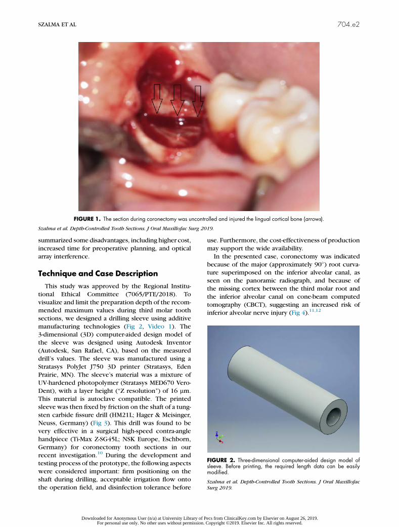
summarized some disadvantages, including higher cost,
increased time for preoperative planning, and optical
array interference.
Technique and Case Description
This study was approved by the Regional Institu-
tional Ethical Committee (7065/PTE/2018). To
visualize and limit the preparation depth of the recom-
mended maximum values during third molar tooth
sections, we designed a drilling sleeve using additive
manufacturing technologies (Fig 2, Video 1). The3-dimensional (3D) computer-aided design model of
the sleeve was designed using Autodesk Inventor
(Autodesk, San Rafael, CA), based on the measured
drill’s values. The sleeve was manufactured using a
Stratasys PolyJet J750 3D printer (Stratasys, Eden
Prairie, MN). The sleeve’s material was a mixture of
UV-hardened photopolymer (Stratasys MED670 Vero-
Dent), with a layer height (‘‘Z resolution’’) of 16 mm.This material is autoclave compatible. The printed
sleeve was then fixed by friction on the shaft of a tung-
sten carbide fissure drill (HM21L; Hager & Meisinger,
Neuss, Germany) (Fig 3). This drill was found to be
very effective in a surgical high-speed contra-angle
handpiece (Ti-Max Z-SG45L; NSK Europe, Eschborn,
Germany) for coronectomy tooth sections in our
recent investigation.10 During the development andtesting process of the prototype, the following aspects
were considered important: firm positioning on the
shaft during drilling, acceptable irrigation flow onto
the operation field, and disinfection tolerance before
use. Furthermore, the cost-effectiveness of production
may support the wide availability.
In the presented case, coronectomy was indicated
because of the major (approximately 90�) root curva-ture superimposed on the inferior alveolar canal, as
seen on the panoramic radiograph, and because of
the missing cortex between the third molar root and
the inferior alveolar canal on cone-beam computed
tomography (CBCT), suggesting an increased risk of
inferior alveolar nerve injury (Fig 4).11,12
FIGURE 1. The section during coronectomy was uncontrolled and injured the lingual cortical bone (arrows).
Szalma et al. Depth-Controlled Tooth Sections. J Oral Maxillofac Surg 2019.
FIGURE 2. Three-dimensional computer-aided design model ofsleeve. Before printing, the required length data can be easilymodified.
Szalma et al. Depth-Controlled Tooth Sections. J Oral Maxillofac
Surg 2019.
SZALMA ET AL 704.e2
Downloaded for Anonymous User (n/a) at University Library of Pecs from ClinicalKey.com by Elsevier on August 26, 2019.For personal use only. No other uses without permission. Copyright ©2019. Elsevier Inc. All rights reserved.
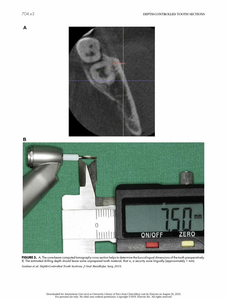
FIGURE3. A, The cone-beam computed tomography cross section helps to determine the buccolingual dimensions of the tooth preoperatively.B, The estimated drilling depth should leave some unprepared tooth material, that is, a security zone lingually (approximately 1 mm).
Szalma et al. Depth-Controlled Tooth Sections. J Oral Maxillofac Surg 2019.
704.e3 DEPTH-CONTROLLED TOOTH SECTIONS
Downloaded for Anonymous User (n/a) at University Library of Pecs from ClinicalKey.com by Elsevier on August 26, 2019.For personal use only. No other uses without permission. Copyright ©2019. Elsevier Inc. All rights reserved.
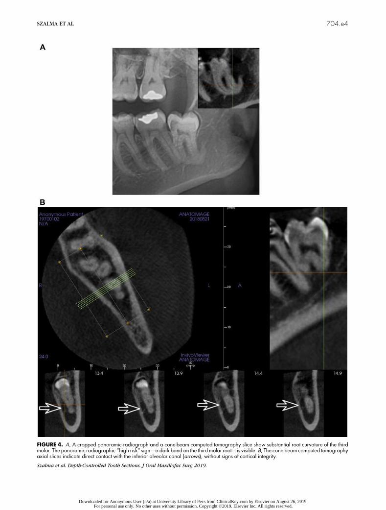
FIGURE 4. A, A cropped panoramic radiograph and a cone-beam computed tomography slice show substantial root curvature of the thirdmolar. The panoramic radiographic ‘‘high-risk’’ sign—a dark band on the third molar root—is visible. B, The cone-beam computed tomographyaxial slices indicate direct contact with the inferior alveolar canal (arrows), without signs of cortical integrity.
Szalma et al. Depth-Controlled Tooth Sections. J Oral Maxillofac Surg 2019.
SZALMA ET AL 704.e4
Downloaded for Anonymous User (n/a) at University Library of Pecs from ClinicalKey.com by Elsevier on August 26, 2019.For personal use only. No other uses without permission. Copyright ©2019. Elsevier Inc. All rights reserved.
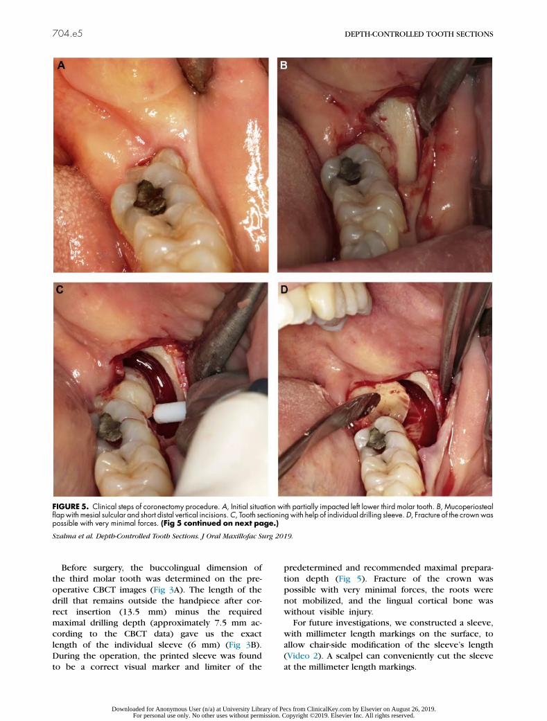
Before surgery, the buccolingual dimension of
the third molar tooth was determined on the pre-
operative CBCT images (Fig 3A). The length of the
drill that remains outside the handpiece after cor-
rect insertion (13.5 mm) minus the requiredmaximal drilling depth (approximately 7.5 mm ac-
cording to the CBCT data) gave us the exact
length of the individual sleeve (6 mm) (Fig 3B).
During the operation, the printed sleeve was found
to be a correct visual marker and limiter of the
predetermined and recommended maximal prepara-
tion depth (Fig 5). Fracture of the crown was
possible with very minimal forces, the roots were
not mobilized, and the lingual cortical bone was
without visible injury.For future investigations, we constructed a sleeve,
with millimeter length markings on the surface, to
allow chair-side modification of the sleeve’s length
(Video 2). A scalpel can conveniently cut the sleeve
at the millimeter length markings.
FIGURE 5. Clinical steps of coronectomy procedure. A, Initial situation with partially impacted left lower third molar tooth. B, Mucoperiostealflapwithmesial sulcular and short distal vertical incisions.C, Tooth sectioningwith help of individual drilling sleeve.D, Fracture of the crownwaspossible with very minimal forces. (Fig 5 continued on next page.)
Szalma et al. Depth-Controlled Tooth Sections. J Oral Maxillofac Surg 2019.
704.e5 DEPTH-CONTROLLED TOOTH SECTIONS
Downloaded for Anonymous User (n/a) at University Library of Pecs from ClinicalKey.com by Elsevier on August 26, 2019.For personal use only. No other uses without permission. Copyright ©2019. Elsevier Inc. All rights reserved.
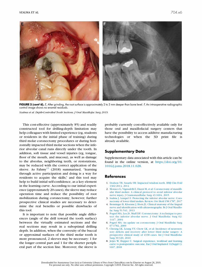
This cost-effective (approximately $5) and readily
constructed tool for drilling-depth limitation mayhelp colleagues with limited experience (eg, students
or residents in the initial phase of training) during
third molar coronectomy procedures or during hori-
zontally impacted third molar sections when the infe-
rior alveolar canal runs directly under the tooth. In
addition, soft tissue and vessel injuries (eg, tongue,
floor of the mouth, and mucosa), as well as damage
to the alveolus, neighboring teeth, or restorations,may be reduced with the correct application of the
sleeve. As Fahmy13 (2018) summarized, ‘‘learning
through active participation and doing is a way for
residents to acquire the skills,’’ and this tool may
help to build initial self-confidence, as a key element
in the learning curve. According to our initial experi-
ence (approximately 20 cases), the sleeve may reduce
operation time and reduce the possibility of rootmobilization during coronectomy; however, further
prospective clinical studies are necessary to deter-
mine the real benefits or possible drawbacks of
this tool.
It is important to note that possible angle differ-
ences (angle of the drill toward the tooth surface)
between the virtually estimated sections and the
real sections may result in a suboptimal drillingdepth. In addition, when the convexity of the buccal
or approximal surfaces of the third molar tooth is
more pronounced, 2 sleeves may be necessary: 1 for
the longer central part and 1 for the shorter periph-
eral part of the section line. Moreover, the sleeve is
probably currently cost-effectively available only for
those oral and maxillofacial surgery centers thathave the possibility to access additive manufacturing
technologies or when the 3D print file is
already available.
Supplementary Data
Supplementary data associated with this article can be
found in the online version, at https://doi.org/10.
1016/j.joms.2018.11.028.
References
1. Dodson TB, Susarla SM: Impacted wisdom teeth. BMJ Clin Evid1302:2014, 2014
2. Monaco G, Vignudelli E, Diazzi M, et al: Coronectomy of mandib-ular third molars: A clinical protocol to avoid inferior alveolarnerve injury. J Craniomaxillofac Surg 43:1694, 2015
3. Szalma J, Lempel E: Protecting the inferior alveolar nerve: Coro-nectomy of lower third molars. Review. Orv Hetil 158:1787, 2017
4. Benninger B, Kloenne J, Horn JL: Clinical anatomy of the lingualnerve and identification with ultrasonography. Br J Oral Maxillo-fac Surg 51:541, 2013
5. Pogrel MA, Lee JS, Muff DF: Coronectomy: A technique to pro-tect the inferior alveolar nerve. J Oral Maxillofac Surg 62:1447, 2004
6. Pogrel MA: An update on coronectomy. J Oral Maxillofac Surg67:1782, 2009
7. Cheung LK, Leung YY, Chow LK, et al: Incidence of neurosen-sory deficits and recovery after lower third molar surgery: Aprospective clinical study of 4338 cases. Int J Oral MaxillofacSurg 39:320, 2010
8. Jerjes W, Hopper C: Surgical experience, workload and learningcurve vs postoperative outcome. Eur J Oral Implantol 11(Suppl 1):S167, 2018
FIGURE 5 (cont’d). E, After grinding, the root surface is approximately 2 to 3 mm deeper than bone level. F, An intraoperative radiographiccontrol image shows no enamel residuals.
Szalma et al. Depth-Controlled Tooth Sections. J Oral Maxillofac Surg 2019.
SZALMA ET AL 704.e6
Downloaded for Anonymous User (n/a) at University Library of Pecs from ClinicalKey.com by Elsevier on August 26, 2019.For personal use only. No other uses without permission. Copyright ©2019. Elsevier Inc. All rights reserved.

9. Emery RW, Korj O, Agarwal R: A review of in-office dynamicimage navigation for extraction of complex mandibular thirdmolars. J Oral Maxillofac Surg 75:1591, 2017
10. Szalma J, Vajta L, Olasz L, Lempel E: Tooth sectioning for coro-nectomy: How to perform? Clin Oral Investig; https://doi.org/10.1007/s00784-018-2466-2, 2018 in press
11. Szalma J, Lempel E, Jeges S, et al: The prognostic value of pano-ramic radiography of inferior alveolar nerve damage aftermandibular third molar removal. Retrospective study of 400
cases. Oral Surg Oral Med Oral Pathol Oral Radiol Endod 109:294, 2010
12. Selvi F, Dodson TB, Nattestad A, et al: Factors that are associ-ated with injury to the inferior alveolar nerve in high-risk pa-tients after removal of third molars. Br J Oral Maxillofac Surg51:868, 2013
13. Fahmy MD: Teaching in oral and maxillofacial surgery trainingprograms: A resident perspective. J Oral Maxillofac Surg 76:2461, 2018
704.e7 DEPTH-CONTROLLED TOOTH SECTIONS
Downloaded for Anonymous User (n/a) at University Library of Pecs from ClinicalKey.com by Elsevier on August 26, 2019.For personal use only. No other uses without permission. Copyright ©2019. Elsevier Inc. All rights reserved.
Materials Research Express
PAPER • OPEN ACCESS
Printing orientation defines anisotropic mechanicalproperties in additive manufacturing of upper limbprostheticsTo cite this article: Peter Maroti et al 2019 Mater. Res. Express 6 035403
View the article online for updates and enhancements.
Recent citationsNovel PLA-CaCO3 composites in additivemanufacturing of upper limb casts andorthotics—A feasibility studyP Varga et al
-
This content was downloaded from IP address 193.6.53.149 on 26/08/2019 at 10:01

Mater. Res. Express 6 (2019) 035403 https://doi.org/10.1088/2053-1591/aaf5a9
PAPER
Printing orientation defines anisotropic mechanical properties inadditive manufacturing of upper limb prosthetics
PeterMaroti1, Peter Varga2, HajnalkaAbraham3, Gyorgy Falk4, Tamas Zsebe5, ZoltanMeiszterics5,SandorMano6, ZoltanCsernatony6, SzilardRendeki2 andMiklosNyitrai1,7,8
1 University of Pecs,Medical School, Department of Biophysics, Hungary2 University of Pecs,Medical School,Medical SimulationCenter, Hungary3 University of Pecs,Medical School, Central ElectronMicroscope Laboratory,Hungary4 Varinex Informatics cPlc, Hungary5 University of Pecs, Faculty of Engineering and IT,Department ofMechanical Engineering, Hungary6 University ofDebrecen, Department ofOrthopaedic Surgery,Hungary7 University of Pécs, Szentágothai ResearchCenter, Hungary8 Author towhomany correspondence should be addressed
E-mail:[email protected]
Keywords: additivemanufacturing, polymer, printing orientation, printing resolution,mechanical testing, scanning electronmicroscopy
AbstractAdditivemanufacturing (AM) technologies are potential future-shaping solutions throughoutmanyspecial applications inmedicine. Themechanical behaviour of the relatedmaterials has not yet beenfully explored.Herewe compared five different industrial quality 3Dprintingmaterials producedusing various AMprocesses that can be potentially used in limb-prosthetic development.We focusedon the anisotropy of themechanical and structural properties of thesematerials by using static anddynamic testingmethods and electronmicroscopy imaging. Both static and dynamic experimentsconfirmed that amongst the three investigated directions (X, Y andZ), theZ orientation demonstrated,with the exception of polyamide test specimens, the lowest resistance againstmechanical forces.Electronmicroscopy images revealed that greatermechanical stability appeared presumably due tothe lengthier cooling time of the individual printed lines. Varying the printing resolutionwe showedhow greatermechanical stability could be achieved, and concluded that special care should be takenwhen designing the AMprocesses intended for the fabrication of objects in support ofmedicalapplications. Often, the use of poor resolution in respect to quality of printing is desirable and canprovide better solutions for actual purposes. These results provide important guidelines in theplanning,manufacturing and implementation of higher developed, well-constructed assistive devices.
Introduction
Additivemanufacturing (AM) technologies have become future-shaping solutions inmany areas includingspecial applications inmedicine. 3Dprinted upper limb-prosthetics offer a significant positive change in lifestylefor thousands of people with a disability worldwide. Several non-profit organizations promote and facilitate thecollaboration among engineers, crafters, tinkerers andmedical professionals to produce these devices [1–6].More than 2,000 children possess custom3Dprinted upper limb prosthetics [7]. Despite their outstandingpotential to improve the social acceptance of the users and the quality of their life [8, 9], there are only limitedinformation available regarding the structural details andmechanical behaviour of 3Dprinted upper-limbprosthetics. Previous studies have shown that themajority of the devices are not scientifically examined, andmost of themwere prepared using Fused depositionmodelling/Fusedfilament fabrication (FDM™/FFF)technology. Other 3Dprinting solutions are also promising [10].
The assistive devices used by upper-limb amputees require both static and dynamic stability [11]. Themostcommonmaterials - due to desktop FDM/FFF printing - in these applications are Polylactic acid (PLA) andAcrylonitrile butadiene styrene (ABS). Polymers, which are not common in prostheticmanufacturing, such as
OPEN ACCESS
RECEIVED
2November 2017
REVISED
20November 2018
ACCEPTED FOR PUBLICATION
3December 2018
PUBLISHED
12December 2018
Original content from thisworkmay be used underthe terms of the CreativeCommonsAttribution 3.0licence.
Any further distribution ofthis workmustmaintainattribution to theauthor(s) and the title ofthework, journal citationandDOI.
© 2018 IOPPublishing Ltd
PolyJet™materials or FDM™ULTEM™, possess outstandingmechanical properties compared to currentlymore commonlymaterials. Polyamide parts,manufactured by selective laser sintering (SLS) technology,mayalso prove to be excellent solutions in the fabrication of functional parts [10, 12]. J TKate et al also state in arecent review that’material strength is also an important point to consider. No predictions have beenmade bythe developers of the 3D-printed handswith respect to the strength of the parts of the printed prostheses.Further research should be performed on the strength and durability of 3D-printed parts [10].
Material science has only recently caught upwith the rapid development of 3Dprintingmachines and hasquickly developed into one of themost dynamically evolving areas when considering the corresponding fields ofresearch. Also, innovative solutions in actuating these devices are appeared in the recent years—such as shape-memory alloys (SMAs), shape-memory polymers (SMPs) or artificialmuscles [13, 14], where 3Dprinting can bea game-changer too [15, 16]. However, 3DCAD simulations can help in prosthetics design [17], thematerialscan be used in the additivemanufacturing process are not fully examined yet. According to the principle ofpersonalizedmedicine, in all cases it is important to establish a framework of criteria for their comprehensionincluding, when andwhichmaterials are advisable in the construction. It was previously shown for some of theapplied substances that the orientation of 3Dprinting affects themechanical properties of the printed objects [5,18–21]. In these studies, the authors showed that there is strong a correlation between the stiffness of 3Dprintedobject and the printing geometry. Severalmaterials—such as ABS, PLA for desktop printers, different SLS,powder-based composites and photopolymers - were testedwith dynamic and staticmeasurements. Theexperiments showed that the layer thickness, orientation and base-material are key elements in additivemanufacturing technologies. However, little information is available regarding the high-grade, industrial 3Dprintingmaterials that can be used in prostheticmanufacturing. Previous studies in this field showed that theprosthetic sockets can bemanufacturedwith 3Dprinters [22–26], but the information regarding otherfunctional parts are limited. Also, it is revealed that not only themechanical properties of the different polymersand composites are not fully explored yet, butwe are not familiar with the degradation process of these 3dprinted parts [27].With the appearance of newmaterials this problemneeds further investigation to include theproperties of newmaterials and to understand themolecular events underlying the appearance of orientationdependentmechanical properties.
In our study, we compared five different industrial-quality 3Dprintingmaterials, intended for use inprosthetic production and development towards the exploration of themost important aspects of the 3Dprinting process of prostheticmanufacturing.We focused on the anisotropy of themechanical properties andstructural characteristics of thesematerials fabricatedwith various AM technologies using static and dynamictests and electronmicroscopy imaging.
Materials andmethods
3DPrintingIn this workwe tested severalmaterials; polyamide, Objet™VeroGrey™, Objet™Digital ABS, FDM™M30ABSand FDM™ULTEM9085. In the experiments, standardized shape test specimens were used. According topreviousfindings, all these polymers are potentially suitable for personalized prosthetic production. The testspecimenswere produced by PolyJet™ technology in the case ofObjet™VeroGrey™ andDigital ABS™,polyamide by SLS technology, ABSM30 andULTEM9085 by FDM™. The printingwas carried out using EOS™Formiga P100™ and in the case of SLS, Stratasys™ Fortus 400mc Large™was used in FDM™, andObjet350Connex3™was used in PolyJet™ technology.
ABS test specimenswere producedwith FDM™ and PolyJet™ technology to investigate the differencesbetweenmechanical stability and structure of the objects produced by the twomethods.We also examineddifferent layer thickness (Z resolution) tomap the effect of resolution on thesemechanical properties anddetermine the correlation between them, including themicroscopic structures of the objects. FDM™ABSspecimensweremade at 0.178 mmand 0.330 mmresolution. ULTEMspecimens were printed at 0.254 mmlayer thickness. Polyamide test bars had 0.1 mm layer thickness andObjet™materials had 0.03 mm (ABS) and0.016 mm (VeroGrey™). The droplet size of the PolyJet™ technologywas 0.042 mm. The size of polyamidegranules varies between 0.04–0.06mms. The temperature was set to 70 °C in case of PolyJet™ technology, to250 °Cat FDM™ABS, between 350–400 °C in case ofULTEMprinting, and to 186 °C at SLS printings. All testbars were producedwith 100% infill density.
In all of the abovementioned, resolutions were applied for objects in their X, Y andZ orientations, i.e.fivepieces of eachwere produced. The layers were determined by the slicing software of the printers according to theplacement of the test bars, demonstrated infigure 1. In the case of the X orientation, the bar lies on its10 mm×80 mmside, Y orientation on the 80 mm×4 mmside andZorientation on the4 mm×10 mmside.
2
Mater. Res. Express 6 (2019) 035403 PMaroti et al
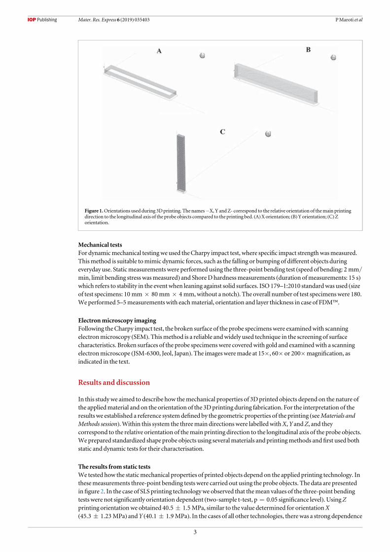
Mechanical testsFor dynamicmechanical testingwe used theCharpy impact test, where specific impact strengthwasmeasured.Thismethod is suitable tomimic dynamic forces, such as the falling or bumping of different objects duringeveryday use. Staticmeasurements were performed using the three-point bending test (speed of bending: 2 mm/
min, limit bending stress wasmeasured) and ShoreDhardnessmeasurements (duration ofmeasurements: 15 s)which refers to stability in the event when leaning against solid surfaces. ISO 179–1:2010 standardwas used (sizeof test specimens: 10 mm×80 mm×4 mm,without a notch). The overall number of test specimenswere 180.We performed 5–5measurements with eachmaterial, orientation and layer thickness in case of FDM™.
Electronmicroscopy imagingFollowing theCharpy impact test, the broken surface of the probe specimens were examinedwith scanningelectronmicroscopy (SEM). Thismethod is a reliable andwidely used technique in the screening of surfacecharacteristics. Broken surfaces of the probe specimens were coveredwith gold and examinedwith a scanningelectronmicroscope (JSM-6300, Jeol, Japan). The imagesweremade at 15×, 60× or 200×magnification, asindicated in the text.
Results and discussion
In this studywe aimed to describe how themechanical properties of 3Dprinted objects depend on the nature ofthe appliedmaterial and on the orientation of the 3Dprinting during fabrication. For the interpretation of theresults we established a reference systemdefined by the geometric properties of the printing (seeMaterials andMethods session).Within this system the threemain directions were labelledwithX,Y andZ, and theycorrespond to the relative orientation of themain printing direction to the longitudinal axis of the probe objects.We prepared standardized shape probe objects using severalmaterials and printingmethods and first used bothstatic and dynamic tests for their characterisation.
The results from static testsWe tested how the staticmechanical properties of printed objects depend on the applied printing technology. Inthesemeasurements three-point bending tests were carried out using the probe objects. The data are presentedinfigure 2. In the case of SLS printing technologywe observed that themean values of the three-point bendingtests were not significantly orientation dependent (two-sample t-test, p=0.05 significance level). UsingZprinting orientationwe obtained 40.5±1.5 MPa, similar to the value determined for orientationX(45.3±1.23 MPa) andY (40.1±1.9 MPa). In the cases of all other technologies, therewas a strong dependence
Figure 1.Orientations used during 3Dprinting. The names−X, Y andZ- correspond to the relative orientation of themain printingdirection to the longitudinal axis of the probe objects compared to the printing bed. (A)Xorientation; (B)Yorientation; (C)Zorientation.
3
Mater. Res. Express 6 (2019) 035403 PMaroti et al
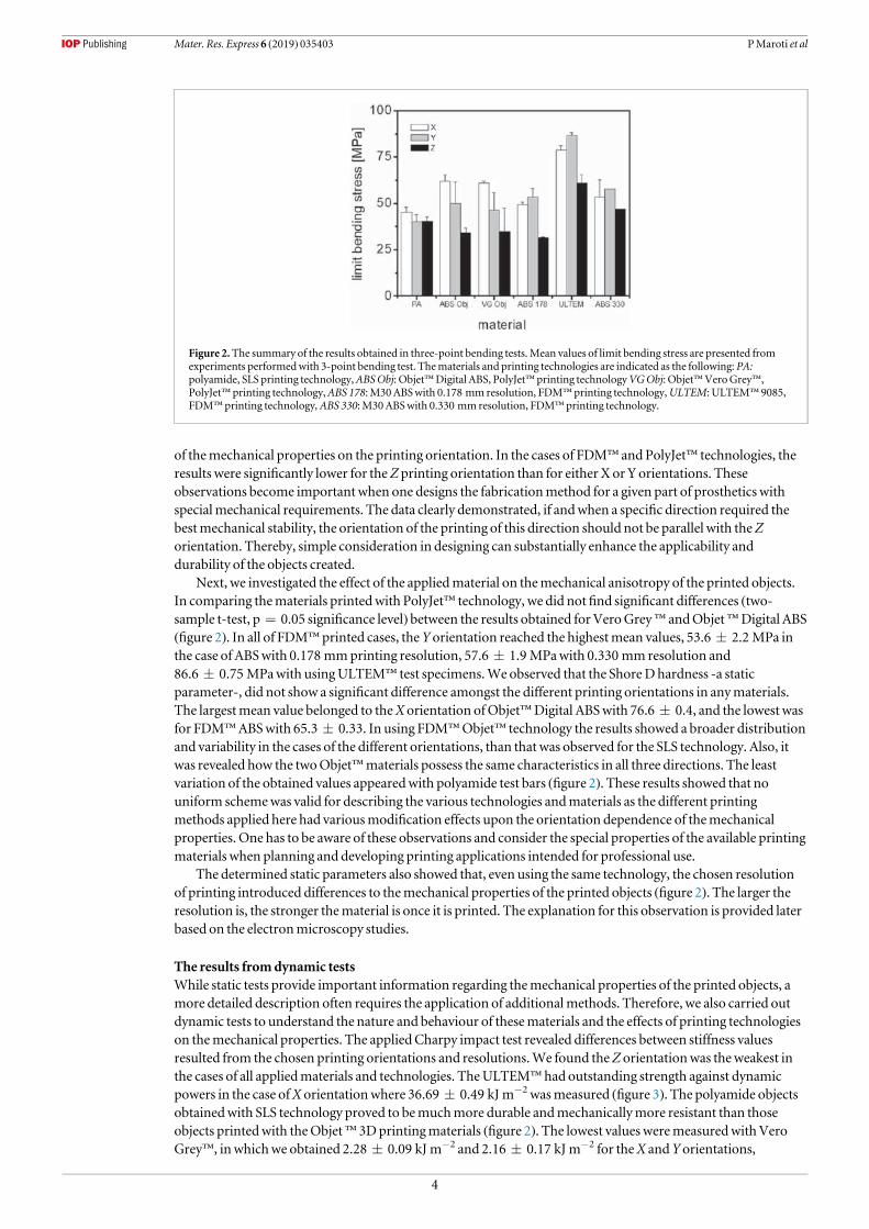
of themechanical properties on the printing orientation. In the cases of FDM™ and PolyJet™ technologies, theresults were significantly lower for theZ printing orientation than for either X or Y orientations. Theseobservations become important when one designs the fabricationmethod for a given part of prosthetics withspecialmechanical requirements. The data clearly demonstrated, if andwhen a specific direction required thebestmechanical stability, the orientation of the printing of this direction should not be parallel with theZorientation. Thereby, simple consideration in designing can substantially enhance the applicability anddurability of the objects created.
Next, we investigated the effect of the appliedmaterial on themechanical anisotropy of the printed objects.In comparing thematerials printedwith PolyJet™ technology, we did notfind significant differences (two-sample t-test, p=0.05 significance level) between the results obtained for VeroGrey™ andObjet™Digital ABS(figure 2). In all of FDM™ printed cases, theY orientation reached the highestmean values, 53.6±2.2 MPa inthe case of ABSwith 0.178 mmprinting resolution, 57.6±1.9 MPawith 0.330 mmresolution and86.6±0.75 MPawith usingULTEM™ test specimens.We observed that the ShoreDhardness -a staticparameter-, did not show a significant difference amongst the different printing orientations in anymaterials.The largestmean value belonged to theX orientation ofObjet™Digital ABSwith 76.6±0.4, and the lowest wasfor FDM™ABSwith 65.3±0.33. In using FDM™Objet™ technology the results showed a broader distributionand variability in the cases of the different orientations, than that was observed for the SLS technology. Also, itwas revealed how the twoObjet™materials possess the same characteristics in all three directions. The leastvariation of the obtained values appearedwith polyamide test bars (figure 2). These results showed that nouniform schemewas valid for describing the various technologies andmaterials as the different printingmethods applied here had variousmodification effects upon the orientation dependence of themechanicalproperties. One has to be aware of these observations and consider the special properties of the available printingmaterials when planning and developing printing applications intended for professional use.
The determined static parameters also showed that, even using the same technology, the chosen resolutionof printing introduced differences to themechanical properties of the printed objects (figure 2). The larger theresolution is, the stronger thematerial is once it is printed. The explanation for this observation is provided laterbased on the electronmicroscopy studies.
The results fromdynamic testsWhile static tests provide important information regarding themechanical properties of the printed objects, amore detailed description often requires the application of additionalmethods. Therefore, we also carried outdynamic tests to understand the nature and behaviour of thesematerials and the effects of printing technologieson themechanical properties. The appliedCharpy impact test revealed differences between stiffness valuesresulted from the chosen printing orientations and resolutions.We found theZ orientationwas theweakest inthe cases of all appliedmaterials and technologies. TheULTEM™ had outstanding strength against dynamicpowers in the case ofX orientationwhere 36.69±0.49 kJ m−2 wasmeasured (figure 3). The polyamide objectsobtainedwith SLS technology proved to bemuchmore durable andmechanicallymore resistant than thoseobjects printedwith theObjet™ 3Dprintingmaterials (figure 2). The lowest values weremeasuredwithVeroGrey™, inwhichwe obtained 2.28±0.09 kJ m−2 and 2.16±0.17 kJ m−2 for theX andY orientations,
Figure 2.The summary of the results obtained in three-point bending tests.Mean values of limit bending stress are presented fromexperiments performedwith 3-point bending test. Thematerials and printing technologies are indicated as the following: PA:polyamide, SLS printing technology,ABSObj: Objet™Digital ABS, PolyJet™printing technologyVGObj: Objet™VeroGrey™,PolyJet™ printing technology,ABS 178:M30ABSwith 0.178 mmresolution, FDM™printing technology,ULTEM: ULTEM™ 9085,FDM™printing technology, ABS 330:M30ABSwith 0.330 mmresolution, FDM™ printing technology.
4
Mater. Res. Express 6 (2019) 035403 PMaroti et al
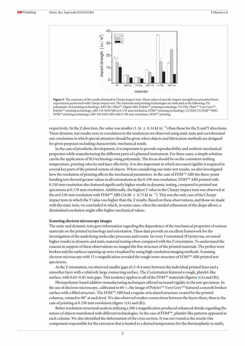
respectively. In the Z direction, the valuewas smaller (1.16±0.14 kJ m−2) than those for theX andYdirections.These dynamic test results were in correlation to the tendencies we observed using static tests and corroboratedour conclusion inwhich special attention should be givenwhen objects and fabricationmethods are designedfor given purposes including characteristicmechanical needs.
In the case of prosthetic development, it is important to provide reproducibility and uniformmechanicalproperties whilemanufacturing the different parts of a planned instrument. For these cases, a simple solutioncan be the application of SLS technology using polyamide. The focus should be on the consistentmeltingtemperature, printing velocity and laser effectivity. It is also important inwhich increased rigidity is required inseveral key parts of the printed systemof objects.When considering our static test results, we also investigatedhow the resolution of printing affects themechanical parameters. In the case of FDM™ABS the three-pointbending test showed greater values in all orientations at the 0.330 mmresolution. FDM™ABSprintedwith0.330 mmresolution also featured significantly higher results in dynamic testing, compared to printed testspecimens at 0.178 mm resolution. Additionally, the highestY value in theCharpy impact tests was observed atthe at 0.330 mmresolutionwith FDM™ABS (24.88±0.73 kJ m−2). This was the only case of the Charpyimpact tests inwhich theY valuewas higher than theX results. Based on these observations, and thosewemadewith the static tests, we concluded inwhich, in some cases, when the needed refinement of the shape allows, adiminished resolutionmight offer highermechanical values.
Scanning electronmicroscopy imagesThe static and dynamic tests gave information regarding the dependence of themechanical properties of variousmaterials on the printed technology and orientation. These data provide an excellent framework for theinvestigation of the underlyingmolecular processes and events. In everyY orientated 3Dprint run, we notedhigher results in dynamic and staticmaterial testingwhen comparedwith theZ orientation. To understand thereasons in support of these observationswe imaged thefine structure of the printedmaterials. The probes werebroken and the surfaces opening upwere visualized by using high resolution imagingmethods. Scanningelectronmicroscopywith 15 xmagnification revealed the rough inner structure of FDM™ABSprinted testspecimens.
At theY orientation, we observed smaller gaps (0.3–0.4 mm) between the individual printed lines and asmoother layer with a relatively large connecting surface. TheZ orientation featured a rough, platelet-likesurface, with 0.65–0.85 mmgaps. This tendency applies to all of the FDM™materials (figures 4(A) and (B)).
Photopolymer based additivemanufacturing techniques offered increased rigidity in the test specimens. Inthe use of electronmicroscopy, calibrated to 60×, the image of PolyJet™VeroGrey™ featured a smooth brokensurfacewith afilled structure. The FDM™ABS had a regular articulated structure created by the printedcolumns, rotated to 90° at each level.We also observedweaker connections between the layers there, than in thecase of printing at 0.330 mm resolution (figure 5(A) and (B)).
Better resolution structural analysis utilizing a 200 xmagnification produced enhanced details regarding thenature of objectsmanifestedwith different technologies. In the case of FDM™, platelet-like patterns appeared ateach column.We also identified the deformation of the cross section. It was not round as the nozzle (thecomponent responsible for the extrusion that is heated to a desired temperature for the thermoplastic tomelt),
Figure 3.The summary of the results obtained inCharpy impact tests.Mean values of specific impact strengths are presented fromexperiments performedwithCharpy impact test. Thematerials and printing technologies are indicated as the following: PA:polyamide, SLS printing technology;ABSObj: Objet™Digital ABS, PolyJet™printing technology;VGObj: Objet™VeroGrey™,PolyJet™ printing technology;ABS 178:M30ABS at 0.178 mmresolution, FDM™ printing technology;ULTEM: ULTEM™ 9085,FDM™printing technology;ABS 330:M30ABSwith 0.330 mmresolution, FDM™ printing.
5
Mater. Res. Express 6 (2019) 035403 PMaroti et al
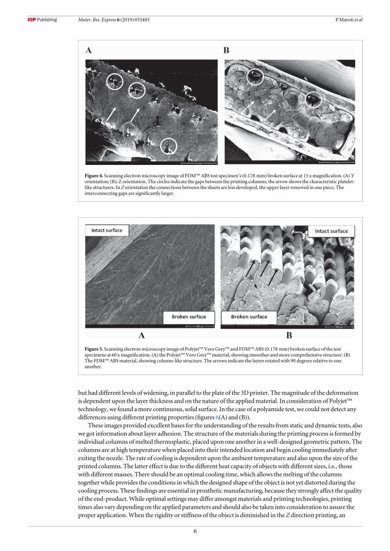
but had different levels of widening, in parallel to the plate of the 3Dprinter. Themagnitude of the deformationis dependent upon the layer thickness and on the nature of the appliedmaterial. In consideration of Polyjet™technology, we found amore continuous, solid surface. In the case of a polyamide test, we could not detect anydifferences using different printing properties (figures 6(A) and (B)).
These images provided excellent bases for the understanding of the results from static and dynamic tests, alsowe got information about layer adhesion. The structure of thematerials during the printing process is formed byindividual columns ofmelted thermoplastic, placed upon one another in awell-designed geometric pattern. Thecolumns are at high temperature when placed into their intended location and begin cooling immediately afterexiting the nozzle. The rate of cooling is dependent upon the ambient temperature and also upon the size of theprinted columns. The latter effect is due to the different heat capacity of objects with different sizes, i.e., thosewith differentmasses. There should be an optimal cooling time, which allows themelting of the columnstogetherwhile provides the conditions inwhich the designed shape of the object is not yet distorted during thecooling process. These findings are essential in prostheticmanufacturing, because they strongly affect the qualityof the end-product.While optimal settingsmay differ amongstmaterials and printing technologies, printingtimes also vary depending on the applied parameters and should also be taken into consideration to assure theproper application.When the rigidity or stiffness of the object is diminished in theZ direction printing, an
Figure 4. Scanning electronmicroscopy image of FDM™ABS test specimen’s (0.178 mm) broken surface at 15 xmagnification. (A)Yorientation; (B); Z orientation. The circles indicate the gaps between the printing columns; the arrow shows the characteristic platelet-like structures. InZ orientation the connections between the sheets are less developed, the upper layer removed in one piece. Theinterconnecting gaps are significantly larger.
Figure 5. Scanning electronmicroscopy image of Polyjet™VeroGrey™ and FDM™ABS (0.178 mm) broken surface of the testspecimens at 60 xmagnification. (A) the Polyjet™VeroGrey™material, showing smoother andmore comprehensive structure. (B)The FDM™ABSmaterial, showing column-like structure. The arrows indicate the layers rotatedwith 90 degrees relative to oneanother.
6
Mater. Res. Express 6 (2019) 035403 PMaroti et al
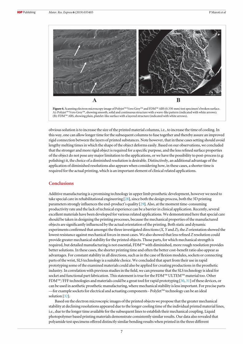
obvious solution is to increase the size of the printedmaterial columns, i.e., to increase the time of cooling. Inthis way, one can allow longer time for the subsequent columns to fuse together and thereby assure an improvedrigid connection between the layers of printed substances. Note however, that in these cases setting should avoidlengthymelting times inwhich the shape of the object deforms easily. Based on our observations, we concludedthat the stronger andmore rigid object is required for a specific purpose, and the less refined surface propertiesof the object do not pose anymajor limitation to the applications, or we have the possibility to post-process (e.g:polishing) it, the choice of a diminished resolution is desirable. Distinctively, an additional advantage of theapplication of diminished resolutions also appears when considering how, in these cases, a shorter time isrequired for the actual printing, which is an important element of clinical related applications.
Conclusions
Additivemanufacturing is a promising technology in upper limb prosthetic development, howeverwe need totake special care in rehabilitational engineering [28], since both the design process, both the 3Dprintingparameters strongly influences the end-product’s quality [29]. Also, at themoment time-consumingproductivity rate and the lack of technical experience can be a barrier in clinical application. Recently, severalexcellentmaterials have been developed for various related applications.We demonstrated here that special careshould be taken in designing the printing processes, because themechanical properties of themanufacturedobjects are significantly influenced by the actual orientation of the printing. Both static and dynamicexperiments confirmed that amongst the three investigated directions (X, Y andZ), theZ orientation showed thelowest resistance againstmechanical forces inmost cases.We also showed that less refinedZ resolution couldprovide greatermechanical stability for the printed objects. Those parts, for whichmechanical strength isrequired, but detailedmanufacturing is not essential, FDM™with diminished,more rough resolution providesbetter solutions. In these cases, the shorter printing time and often the better cost-benefit ratio also appear asadvantages. For constant stability in all directions, such as in the case offlexionmodules, sockets or connectingparts of thewrist, SLS technology is a suitable choice.We concluded that apart from their use in rapidprototyping some of the examinedmaterials could also be applied for creating productions in the prostheticindustry. In correlationwith previous studies in thefield, we can presume that the SLS technology is ideal forsocket and functional part fabrication. This statement is true for the FDM™ULTEM™material too.OtherFDM™/FFF technologies andmaterials could be a great tool for rapid prototyping [30, 31] of these devices, orcan be used in aesthetic prostheticmanufacturing, wheremechanical stability is less important. For precise parts—for example sockets for electrical and actuating components - PolyJet™ technology can be an idealsolution [32].
Based on the electronmicroscopic images of the printed objects we propose that the greatermechanicalstability at declining resolutions appeared due to the longer cooling time of the individual printedmaterial lines,i.e., due to the longer time available for the subsequent lines to establish theirmechanical coupling. Liquidphotopolymer based printingmaterials demonstrate consistently similar results. Our data also revealed thatpolyamide test specimens offered distinctly similar bending results when printed in the three different
Figure 6. Scanning electronmicroscopy image of Polyjet™VeroGrey™ and FDM™ABS (0.330 mm) test specimen’s broken surface.A): Polyjet™VeroGrey™, showing smooth, solid and continuous structurewith awave-like pattern (indicatedwithwhite arrows).(B): FDM™ABS, showing plain, platelet-like surface with a layered structure (indicatedwithwhite arrows).
7
Mater. Res. Express 6 (2019) 035403 PMaroti et al
orientations. This observationwas likely attributed to the constantmelting processes due to the application oflasers (30W,CO2) during the printing process. The SEM images showed that the layer adhesion—mainly inFDM/FFF technology - should be improved. For this problem, gamma-irradiation can be an effective solution,according to previous study [33], since it is revealed that the adhesion and orientation [34] between layers are keypoints in AM technologies.. The results revealed that further investigations are necessary in this area, andwillprovide important guidelines for the planning andmanufacturing of well-constructed assistive devices[10].
Acknowledgments
We thank JonMarquette for critically reading themanuscript. This researchwas supported by a grant from theNational Research, Development and InnovationOffice and the EuropeanUnion (GINOP2.3.2-15-2016-00022). The present scientific contribution is dedicated to the 650th anniversary of the foundation of theUniversity of Pécs, Hungary.
ORCID iDs
MiklosNyitrai https://orcid.org/0000-0002-6229-4337
References
[1] Zuniga J et al 2015Cyborg beast: a low-cost 3d-printed prosthetic hand for childrenwith upper-limb differencesBMCResNotes 8 10[2] Resnik L et al 2012Advanced upper limb prosthetic devices: implications for upper limbprosthetic rehabilitationArch PhysMed
Rehabil 93 710–7[3] Smurr LM,Gulick K, YancosekK andGanzO 2008Managing the upper extremity amputee: a protocol for success J HandTher 21
160–75 quiz 76[4] Kendall F, GretschHDL, PeddadaKV,DeekenCR,Wall L B andGoldfarbCA 2015Development of novel 3D-printed robotic
prosthetic for transradial amputeesProsthet. Orthot. Int. 40 400–3[5] Ramot Y,Haim-ZadaM,DombA J andNyska A 2016 Biocompatibility and safety of PLA and its copolymersAdv. Drug. Deliv. Rev. 107
153–62[6] Buehler E et al 2015 Sharing is caring: assistive technology designs on thingiverse Proc. of the 33rdAnnual ACMConf. onHuman Factors
in Computing Systems (Seoul, Republic of Korea: ACM)pp. 525–34 https://dl.acm.org/citation.cfm?id=2702123.2702525[7] (http://enablingthefuture.org) 2014[8] JamesMA, Bagley AM,BrasingtonK, Lutz C,McConnell S andMolitor F 2006 Impact of prostheses on function and quality of life for
childrenwith unilateral congenital below-the-elbow deficiency J Bone Joint Surg Am 88 2356–65[9] Hickey BM,Woo ST and Shady S F 2017Modular prosthetic design for transtibial child amputeesASME2017 International
Mechanical Engineering Congress and ExpositionIMECE2017-70901[10] tenKate J, Smit G andBreedveld P 2017 3D-printed upper limbprostheses: a reviewDisability andRehabilitation: Assistive Technology
12 300–14[11] LakeC 2008The evolution of upper limbprosthetic socket design Journal of Prosthetics andOrthotics 20 85–92[12] Ligon SCLR, Stampfl J, GurrM andMülhaupt R 2017 Polymers for 3Dprinting and customized additivemanufacturingChem. Rev.
(https://doi.org/10.1021/acs.chemrev.7b00074)[13] Andrianesis K andTzes A 2015Development and control of amultifunctional prosthetic handwith shapememory alloy actuators
Journal of Intelligent&Robotic Systems 78 257–89[14] LianjunW,Monica J deA, LokeshKumar S, Richard StevenR, RayHB andYonas T 2017Compact and low-cost humanoid hand
powered by nylon artificialmusclesBioinsp. Biomim. 12 026004[15] KhooZX et al 2015 3Dprinting of smartmaterials: a review on recent progresses in 4DprintingVirtual and Physical Prototyping 10
103–22[16] Wu J et al 2016Multi-shape active composites by 3Dprinting of digital shapememory polymers Sci. Rep. 6 24224[17] Zollo L, Roccella S, Guglielmelli E, CarrozzaMCandDario P 2007 Biomechatronic design and control of an anthropomorphic
artificial hand for prosthetic and robotic applications IEEE/ASMETrans.Mechatronics 12 418–29[18] Farzadi A, Solati-HashjinM,Asadi-EydivandMandAbuOsmanNA2014 Effect of layer thickness and printing orientation on
mechanical properties and dimensional accuracy of 3Dprinted porous samples for bone tissue engineering PLoSOne 9 e108252[19] MKBMTandPearce JM2014Mechanical properties of components fabricatedwith open-source 3Dprinters under realistic
environmental conditions J.Mater. Des. 117 10212–90[20] VegaV,Clements J, LamT, AbadA, Fritz B,UlaN and Es-SaidOS 2011The effect of layer orientation on themechanical properties
andmicrostructure of a polymer J.Mater. Eng. Perform. 20 978–88[21] KimDL,Hwan I andChoHY2015A Study on themechanical properties of additivemanufactured polymermaterialsTransactions of
the Korean Society ofMechanical EngineersA 39 773–80[22] Bill R et al 2007Advanced trans-tibial socket fabrication using selective laser sintering Prosthet. Orthot. Int. 31 88–100[23] NgP, Lee P SV andGoh JCH2002Prosthetic sockets fabrication using rapid prototyping technologyRapid Prototyping Journal 8 53–9[24] Shuxian Z,Wanhua Z andBingheng L 3D reconstruction of the structure of a residual limb for customising the design of a prosthetic
socketMedical Engineering and Physics 27 67–74[25] ChenRK, Jin Y-A,Wensman J and ShihA 2016Additivemanufacturing of customorthoses and prostheses—A reviewAdditive
Manufacturing 12 77–89[26] SengehDM2012Advanced prototyping of variable impedance prosthetic sockets for trans-tibial amputees: polyjetmatrix 3Dprinting
of comfortable prosthetic sockets using digital anatomical data [master]Massachusetts Institute of Technology
8
Mater. Res. Express 6 (2019) 035403 PMaroti et al

[27] PandeyR 2014 Photopolymers in 3Dprinting applicationsArcada—Nylands svenska yrkeshögskola: Arcada -Nylands svenskayrkeshögskola
[28] MarekMEM, Ziarnecki Ł, Stańczak S, Kawalec P andMikołajewski D 2014 3D printing Technologies in Rehabilitation Engineering:Nicolaus Copernicus University in Toruń
[29] CunicoMWM2013 Study and optimisation of FDMprocess parameters for support-material-free deposition offilaments andincreased layer adherenceVirtual and Physical Prototyping 8 127–34
[30] Gwamuri JEPaJMP J 2016Open source 3Dprinters: an appropriate technology for developing communities Proc. to the 7th Int. Conf.onAppropriate Technology (Victoria Falls, Zimbabwe) (https://doi.org/10.31219/osf.io/uq9g6)
[31] Kiełbus A, Furyk–Grabowska K andOstrowskaK 2016Application of FFFmethod in orthopedicsMachineDynamics Research 193 175[32] Riemenschneider J,Mitkus R andVasista S 2017 Integration of Actuators by Additive LayerManufacturing ASME2017Conference on
SmartMaterials, Adaptive Structures and Intelligent SystemsSMASIS2017-3764[33] Shaffer S, YangK,Vargas J, Di PrimaMAandVoitW2014On reducing anisotropy in 3Dprinted polymers via ionizing radiation
Polymer 55 5969–79[34] AnnaB and SelçukG2003Mechanical characterization of parts fabricated using fused depositionmodelingRapid Prototyping Journal 9
252–64
9
Mater. Res. Express 6 (2019) 035403 PMaroti et al
Testing of innovative materials for medical additive manufacturingby DTA
P. Maroti1 • P. Varga2 • A. Ferencz3 • Z. Ujfalusi1 • M. Nyitrai1,4 • D. L}orinczy1
Received: 10 May 2018 / Accepted: 16 October 2018 / Published online: 26 October 2018� Akademiai Kiado, Budapest, Hungary 2018
AbstractAdditive manufacturing technologies revolutionize many aspects of our everyday life. Biomedical applications benefit a lot
from 3D printing. From surgical guides, patterns to custom-made splints and casts, several medical devices can be easily
produced or prototyped with FFF/FDM technologies. New materials regularly appear on the market; therefore, the sci-
entifically accurate and practical information is not available, and we are lack of information regarding mechanical and
thermal stability of the printed products. In addition, these parameters are essential in setting and optimizing the 3D
printers. In our study, we aimed to analyze two different, unique PLA/CaCO3 composites in the form of additive man-
ufacturing filament, with DTA. We tested the HDT form of PLA in pellet and filament form too. The results showed that
these composites based on their thermal characteristics can be suitable for 3D print biomedical devices such as orthoses,
casts, medical models and surgical guides too; therefore, their further examination should be important, regarding
mechanical characteristics.
Keywords PLA composites � 3D medical printing � TG/DTA
Introduction
Additive manufacturing (AM) has become an emerging
technology not only in industrial applications (e.g., [1–4])
but in many medical fields, such as intelligent drug design
process [5–9], surgery planning, modeling and in the fields
of tissue engineering [10–14], cast and splint production
[15–18]. These application areas are strongly relying on
biocompatible polymers and composites. Previous studies
have shown worldwide that the desktop fused filament
fabrication/fused deposit modeling (FFF/FDM) is the most
commonly used additive manufacturing technology, which
mostly uses PLA (poly-lactic acid) and ABS (acrylonitrile
butadiene styrene) filaments in pure and composite form.
Since the mechanical properties and the quality of 3D
printed products and prototypes strongly depend on the
different printing settings [19], it is essential to understand
the behavior of these thermoplastic polymers. In case of
preoperative assessments and physical interventions with
the pathological model, FFF/FDM technology has proven
to be a suitable tool, but also considered as an unreliable
method with narrow material characteristics [20, 21]. PLA,
a biocompatible and biodegradable material, is a widely
used polymer for creating unique materials for medical 3D
printing. Studies have investigated different PLA com-
posites and bio-nanocomposites from the thermal and
mechanical aspects also. These studies have shown that the
addition of different compounds like ZnO/Cu:Ag [22, 23],
hydrotalcite [24], carbon [25], cellulose [26, 27] or bis-
DOPO-phosphates [28] can strongly modify the mechani-
cal, thermal, degradation processes and biological behavior
of PLA. The addition of ZnO and its complexes causes a
significant increase in UV resistance, and the composite
develops antibacterial effects. Crystallinity rate and
& D. L}[email protected]
1 Department of Biophysics, Medical School, University of
Pecs, Szigeti U. 12, Pecs 7624, Hungary
2 Department of Surgical Research and Techniques, Medical
School, University of Pecs, Szigeti u. 12, Pecs 7624, Hungary
3 Department of Surgical Research and Techniques, Medical
Faculty, Semmelweis University, Budapest Nagyvarad
Square 4, Budapest 1089, Hungary
4 Szentagothai Research Center, University of Pecs, Ifjusag u.
20, Pecs 7624, Hungary
123
Journal of Thermal Analysis and Calorimetry (2019) 136:2041–2048https://doi.org/10.1007/s10973-018-7839-x(012 3456789().,- volV)(0123456789().,-volV)
thermal stability also increased. Hydrotalcites, as nucleat-
ing agents, decrease viscosity in the composite with PLA,
and it elevates the thermo-mechanical degradation rate of
the matrix. Carbon and bis-DOPO-phosphate as an addition
to PLA significantly increase the thermal stability of the
composite. In case of cellulose, the effects are depending
on the pretreatment of the fibers. Adding untreated nano-
fibers to PLA matrix results in higher crystallinity, while
the silanized form increases both adhesion and cold crys-
tallization temperature. These studies and experiments
regarding CaCO3/PLA composites showed that the con-
centration of CaCO3 strongly determines the thermal and
mechanical stability of the material. Too high concentra-
tion (above 70%) can cause an extreme rigidity and frac-
tures catastrophically, but in lower values, Young’s
modulus and strain-at-break can increase. It revealed in
these cases that the crystallization temperature and its
degree are much higher, compared to neat PLA. Activation
energy (Ea) increased in case of these studies, and these
materials have a severe potential in biomedical use. DTA/
TG and DSC/TG methods are key tools in composite
related investigations/experiments [25, 29–32]. Most of the
related investigations have reported the increase in thermal
and mechanical stability [35–38]. Studies have been made
regarding medical CaCO3/PLA composites [33–38] pro-
duced mainly with injection molding techniques. The
results showed that the concentration of the CaCO3
strongly influences the thermal and mechanical behavior of
the material, and, because of this fact, the quality of the
product. Limited information is available regarding the
additive manufacturing of these promising composites,
despite the fact that they are promising candidates for
several different biomedical AM applications.
Development and application of novel materials in
medical applications are expected to foster better methods
and technologies in healthcare systems. In our present
study, we aimed to examine the thermal behavior of two
unique composite materials (their exact composition is
under patent procedures) designed especially for additive
manufacturing for medical use cases. We carried out our
investigations using DTA/TG methods. The materials were
made with twin-screw extruders for desktop FFF/FDM
printers. They contained a relatively high amount of
CaCO3, and thus, they can be potentially used mainly for
orthotics, splint and cast manufacturing and medical
modeling. We have also investigated the pelleted form of
PLA, in untreated and HDT (heat deflection temperature)
form, to explore the effects of extrusion process on the
thermal properties. Based on previous observations and our
current results, we concluded that these composites could
provide great solutions for medical modeling and proto-
typing purposes.
Materials and methods
Materials
PLA
We have tested different PLA pellets (raw materials) and
PLA-based plastic fibers made experimentally with twin-
screw extruder by Filamania Limited Liability Company
(LLC/HU, H-2310 Szigetszentmiklos, Feny}ofa str. 23)
planned for usage in additive manufacturing technology
(FFF/FDM printing). The base raw material was purchased
from Natureworks LLC/US (15305 Minnetonka Boulevard
Minnetonka, MN 55345 USA). The density of raw material
(pellet) was between 1.23 and 1.25 g cm-3, with approx.
67% amorphous and 37% crystalline structure. The D-lac-
tide content was 1.2%. We had two raw materials: a basic
one and a special heat-treated, to achieve higher heat
deflection temperature (HDT) pellet. We checked both
samples in normal raw material form and after a heat
treatment at 105 �C for 1 h. In case of printing, the rec-
ommended speed of the print head in X–Y direction is
60 mm s-1 and the thread pull speed is about
15–20 mm s-1. The proposed printing temperature for
PLA is 215 �C.
PLA-‘‘Gypsum’’
It is a poly-lactic acid-based composite containing calcium
carbonate powder (CaCO3 with 50% m/m ratio). It made
from transparent base material with a three-time extrusion
process, with a thickness (diameter) of 1.75 ± 0.05 mm.
(Other information is under patent.) Its usage can be rele-
vant in modeling and prototyping processes, e.g., in pro-
ducing of individual fracture fixes made with 3D printing.
Proposed printing temperature: 195–220 �C is recom-
mended for 100–400 micron print thickness with reduced
print head/extruder and tray sink speed.
PLA-‘‘model’’
It differs from PLA-Gypsum only in calcium carbonate
content. (Here it is only 20% m/m ratio.)
PLA-‘‘transparent’’
It is a naturally transparent poly-lactic acid. Because of its
transparent character and other physical properties, it is
primarily suitable for modeling (demonstration tools,
experimental tools and prototypes). Its thickness and
printing parameters are the same as in case of the first two
fibers.
2042 P. Maróti et al.
123
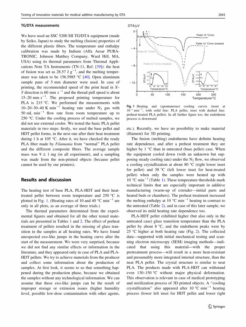
TG/DTA measurements
We have used an SSC 5200 SII TG/DTA equipment (made
by Seiko, Japan) to study the melting (fusion) properties of
the different plastic fibers. The temperature and enthalpy
calibration was made by Indium (Alfa Aesar PURA-
TRONIC, Johnson Matthey Company, Ward Hill, MA,
USA) using its thermal parameters from Thermal Appli-
cations Note TA Instruments (TN-11, Ref. [39]): the heat
of fusion was set as 28.57 J g-1, and the melting temper-
ature was taken to be 156.5985 �C [40]. Open aluminum
sample pans of 5 mm diameter were used. In case of
printing, the recommended speed of the print head in X–
Y direction is 60 mm s-1 and the thread pull speed is about
15–20 mm s-1. The proposed printing temperature for
PLA is 215 �C. We performed the measurements with
10–20–30–40 K min-1 heating rate under N2 gas with
50 mL min-1 flow rate from room temperature up to
250 �C. Under the cooling process of melted samples, we
did not use external cooler. We tested the basic PLA pellet
materials in two steps: firstly, we used the base pellet and
HDT pellet forms, in the next one after their heat treatment
during 1 h at 105 �C. After it, we have checked the ready
PLA fiber made by Filamania from ‘‘normal’’ PLA pellet
and the different composite fibers. The average sample
mass was 9 ± 1 mg (in all experiment), and a sampling
was made from the non-printed objects (because pellet
cannot be used by our printers).
Results and discussion
The heating test of base PLA, PLA-HDT and their heat-
treated pellet between room temperature and 250 �C is
plotted in Fig. 1. (Heating rates of 10 and 40 �C min-1 are
only in all plots, as an average of three trials.)
The thermal parameters determined from the experi-
mental figures and obtained for all the other tested mate-
rials are presented in Tables 1 and 2. The effect of preheat
treatment of pellets resulted in the missing of glass tran-
sition in the samples at all heating rates. We have found
unexpected exo-like jumps in the heating curve after the
start of the measurement. We were very surprised, because
we did not find any similar effects or information in the
literature, and they appeared only in case of PLA and PLA-
HDT pellets. We try to achieve materials from the producer
and collect some information about the production of
samples. At first look, it seems to us that something hap-
pened during the production phase, because we obtained
the samples without any technological information. We can
assume that these exo-like jumps can be the result of
improper storage or extrusion issues (higher humidity
level, possible low-dose contamination with other agents,
etc.). Recently, we have no possibility to make material
(filament) for 3D printing.
The fusion (melting) endotherms have definite heating
rate dependence, and after a preheat treatment they are
higher by 1 �C than in untreated (base pellet) case. When
the equipment cooled down (with an unknown but sup-
posing steady cooling rate) under the N2 flow, we observed
a cooling crystallization at about 80 �C (right lower inset
for pellet) and 58 �C (left lower inset for heat-treated
pellet) when only the samples were heated up with
10 �C min-1 (Table 1). These temperature thresholds mark
technical limits that are especially important in additive
manufacturing (warm-up of extruder—initial parts and
heated beds or chambers). The preheat treatment increased
the melting enthalpy at 10 �C min-1 heating in contrast to
the untreated (Table 2), and in case of this later sample, we
observed its mild heating rate dependence too.
PLA-HDT pellet exhibited higher (but also only in the
untreated case) glass transition temperature than the PLA
pellet by about 8 �C, and the endotherm peaks were by
25 �C higher at both heating rate (Fig. 2). The collected
data—supported with initial mechanical testing and scan-
ning electron microscopy (SEM) imaging methods—indi-
cated that using this material—with the proper
pretreatment process—will result in a more heat-resistant
and presumably more integrated internal structure, than the
neat PLA pellet. The crystal structure is similar to neat
PLA. The products made with PLA-HDT can withstand
even 130–150 �C without major physical deformation.
This observation is relevant in case of medical prototyping
and sterilization process of 3D printed objects. A ‘‘cooling
crystallization’’ also appeared after 10 �C min-1 heating
process (lower left inset for HDT pellet and lower right
500 100 150 200Temperature/°C
250
0
– 4
– 8
– 12
DTA/µV
Temperature/°C Temperature/°C
Pellet 10 °C/minEndo
Exo Exo
Pellet 40 °C/min
Pellet 10 °C/min (treated)
Pellet 40 °C/min (treated)
DT
A/µ
V
DT
A/µ
V
40
0.3
0.2
0.1
0.0
60 80 100 120 40
0.15
0.10
0.05
0.00
– 0.0550 60 70 80
Fig. 1 Heating and (spontaneous) cooling curves (inset at
10 � min-1, with solid line: PLA pellet, inset with dashed line:
preheat-treated PLA pellet). In all further figure too, the endotherm
process is downward
Testing of innovative materials for medical additive manufacturing by DTA 2043
123
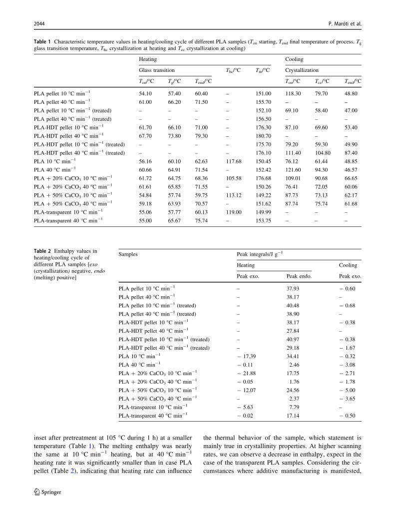
inset after pretreatment at 105 �C during 1 h) at a smaller
temperature (Table 1). The melting enthalpy was nearly
the same at 10 �C min-1 heating, but at 40 �C min-1
heating rate it was significantly smaller than in case PLA
pellet (Table 2), indicating that heating rate can influence
the thermal behavior of the sample, which statement is
mainly true in crystallinity properties. At higher scanning
rates, we can observe a decrease in enthalpy, expect in the
case of the transparent PLA samples. Considering the cir-
cumstances where additive manufacturing is manifested,
Table 1 Characteristic temperature values in heating/cooling cycle of different PLA samples (Ton starting, Tend final temperature of process. Tgglass transition temperature, Thc crystallization at heating and Tcc crystallization at cooling)
Heating Cooling
Glass transition Thc/�C Tm/�C Crystallization
Ton/�C Tg/�C Tend/�C Ton/�C Tcc/�C Tend/�C
PLA pellet 10 �C min-1 54.10 57.40 60.40 – 151.00 118.30 79.70 48.80
PLA pellet 40 �C min-1 61.00 66.20 71.50 – 155.70 – – –
PLA pellet 10 �C min-1 (treated) – – – – 152.10 69.10 58.40 47.00
PLA pellet 40 �C min-1 (treated) – – – – 156.50 – – –
PLA-HDT pellet 10 �C min-1 61.70 66.10 71.00 – 176.30 87.10 69.60 53.40
PLA-HDT pellet 40 �C min-1 67.70 73.80 79.30 – 180.70 – – –
PLA-HDT pellet 10 �C min-1 (treated) – – – – 175.70 79.20 59.30 49.90
PLA-HDT pellet 40 �C min-1 (treated) – – – – 176.10 111.40 104.80 87.40
PLA 10 �C min-1 56.16 60.10 62.63 117.68 150.45 76.12 61.44 48.85
PLA 40 �C min-1 60.66 64.91 71.54 – 152.42 121.60 94.30 46.57
PLA ? 20% CaCO3 10 �C min-1 61.72 64.75 68.36 105.58 176.68 109.01 90.68 66.65
PLA ? 20% CaCO3 40 �C min-1 61.61 65.85 71.55 – 150.26 76.41 72.05 60.06
PLA ? 50% CaCO3 10 �C min-1 54.84 57.74 59.75 113.12 149.22 87.73 73.13 62.17
PLA ? 50% CaCO3 40 �C min-1 59.18 63.93 70.57 – 151.62 87.74 75.74 61.68
PLA-transparent 10 �C min-1 55.06 57.77 60.13 119.00 149.99 – – –
PLA-transparent 40 �C min-1 55.00 65.67 75.74 – 153.75 – – –
Table 2 Enthalpy values in
heating/cooling cycle of
different PLA samples [exo
(crystallization) negative, endo
(melting) positive]
Samples Peak integrals/J g-1
Heating Cooling
Peak exo. Peak endo. Peak exo.
PLA pellet 10 �C min-1 – 37.93 - 0.60
PLA pellet 40 �C min-1 – 38.17 –
PLA pellet 10 �C min-1 (treated) – 40.48 - 0.68
PLA pellet 40 �C min-1 (treated) – 38.90 –
PLA-HDT pellet 10 �C min-1 – 38.17 - 0.38
PLA-HDT pellet 40 �C min-1 – 27.84 –
PLA-HDT pellet 10 �C min-1 (treated) – 40.97 - 0.38
PLA-HDT pellet 40 �C min-1 (treated) – 29.18 - 1.67
PLA 10 �C min-1 - 17.39 34.41 - 0.32
PLA 40 �C min-1 - 0.11 2.46 - 3.08
PLA ? 20% CaCO3 10 �C min-1 - 21.88 17.75 - 2.71
PLA ? 20% CaCO3 40 �C min-1 - 0.05 1.76 - 1.78
PLA ? 50% CaCO3 10 �C min-1 - 12.07 24.56 - 5.00
PLA ? 50% CaCO3 40 �C min-1 – 2.37 - 3.65
PLA-transparent 10 �C min-1 - 5.63 7.79 –
PLA-transparent 40 �C min-1 - 0.02 17.14 - 0.50
2044 P. Maróti et al.
123
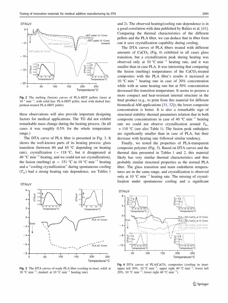
these observations will also provide important designing
factors for medical applications. The TG did not exhibit
remarkable mass change during the heating process. (In all
cases it was roughly 0.5% for the whole temperature
range.)
The DTA curve of PLA fiber is presented in Fig. 3. It
shows the well-known parts of its heating process: glass
transition (between 60 and 65 �C depending on heating
rate), crystallization (* 118 �C, but it disappeared at
40 �C min-1 heating, and we could not see crystallization),
the fusion (melting) at * 151 �C in 10 �C min-1 heating
and a ‘‘cooling crystallization’’ during spontaneous cooling
(Tcc) had a strong heating rate dependence, see Tables 1
and 2). The observed heating/cooling rate dependence is in
a good correlation with data published by Balazs et al. [41].
Comparing the thermal characteristics of the different
pellets and the PLA fiber, we can deduce that in fiber form
can it save crystallization capability during cooling.
The DTA curves of PLA fibers treated with different
amounts of CaCO3 (Fig. 4) exhibited in all cases glass
transition, but a crystallization peak during heating was
observed only at 10 �C min-1 heating rate, and it was
smaller than in case PLA. It was interesting that comparing
the fusion (melting) temperatures of the CaCO3-treated
composites with the PLA fiber’s results it increased at
10 �C min-1 heating rate in case of 20% concentration
while with at same heating rate but at 50% concentration
decreased this transition temperature. It seems to possess a
more compact and heat-resistant internal structure in the
final product (e.g., to print from this material for different
biomedical AM applications [31, 32]); the lower composite
concentration is better. It is also a remarkable sign of
structural stability–thermal parameters relation that in both
composite concentrations in case of 40 �C min-1 heating
rate we could not observe crystallization around Thc-= 110 �C (see also Table 1). The fusion peak enthalpies
are significantly smaller than in case of PLA, but their
decrease with heating rate followed similar tendency.
Finally, we tested the properties of PLA-transparent
composite polymer (Fig. 5). Based on DTA curves and the
thermal data presented in Tables 1 and 2, this material
likely has very similar thermal characteristics and thus
probably similar structural properties as the normal PLA
fiber. The glass transition and main endotherm tempera-
tures are in the same range, and crystallization is observed
only at 10 �C min-1 heating rate. The missing of crystal-
lization under spontaneous cooling and a significant
0
– 5
– 10
– 15
– 20
DTA/µV
500 100 150 200Temperature/°C
250
Temperature/°C90 10050 60 70 80
Temperature/°C9050 60 70 80
DT
A/µ
V
DT
A/µ
V
0.15
0.12
0.09
0.00
0.03
0.06
0.12
0.09
0.00
0.03
0.06Exo Exo
Endo
HDT pellet 40 °C/minHDT pellet 10 °C/min
HDT pellet 40 °C/min
HDT pellet 10 °C/min
(treated)(treated)
Fig. 2 The melting (fusion) curves of PLA-HDT pellets (inset at
10 � min-1, with solid line: PLA-HDT pellet, inset with dashed line:
preheat-treated PLA-HDT pellet)
500 100 150 200
Temperature/°C250
6
4
2
0
– 2
– 4
– 6
– 8
DTA/µV
Endo
Temperature/°C12010040 60 80
DT
A/µ
V
0.3
0.2
0.1
0.0
Temperature/°C70 7550 55 60 65
DT
A/µ
V
0.08
0.06
0.00
0.02
0.04 Exo Exo
PLA 10 °C/min
PLA 40 °C/min
Fig. 3 The DTA curves of ready PLA fiber (cooling in inset, solid: at
10 �C min-1; dashed: at 10 �C min-1 heating rate)
50
8
4
0
– 4
– 8
– 12
100 150 200
Temperature/°C
Temperature/°C
Temperature/°C
PLA + 50% CaCO3 at 10 °C/min
PLA + 20% CaCO3 at 10 °C/min
PLA + 20% CaCO3 at 40 °C/min
PLA + 50% CaCO3 at 40 °C/min
Temperature/°C
Temperature/°C
Endo
Exo
Exo Exo
Exo
600.0
0.2
0.4
0.6
0.8
70 80 90 100 110 60 70 80 90 100 110
60 70 80 90 100 11060
0.5
0.40.3
0.20.1
0.0
0.4
0.3
0.2
0.1
0.0
0.4
0.3
0.2
0.1
0.0
70 80 90 100 110
DTA/µV
DT
A/µ
V
DT
A/µ
V
DT
A/µ
V
DT
A/µ
V
250
Fig. 4 DTA curves of PLA/CaCO3 composites (cooling in inset:
upper left 50%, 10 �C min-1; upper right 40 �C min-1; lower left
20%, 10 �C min-1; lower right 40 �C min-1)
Testing of innovative materials for medical additive manufacturing by DTA 2045
123
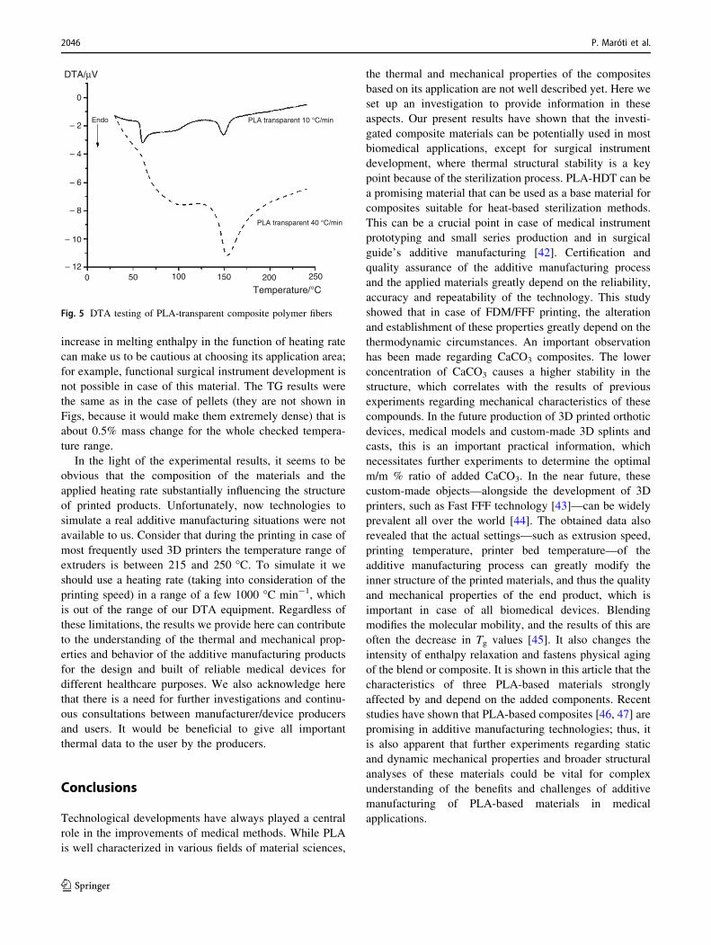
increase in melting enthalpy in the function of heating rate
can make us to be cautious at choosing its application area;
for example, functional surgical instrument development is
not possible in case of this material. The TG results were
the same as in the case of pellets (they are not shown in
Figs, because it would make them extremely dense) that is
about 0.5% mass change for the whole checked tempera-
ture range.
In the light of the experimental results, it seems to be
obvious that the composition of the materials and the
applied heating rate substantially influencing the structure
of printed products. Unfortunately, now technologies to
simulate a real additive manufacturing situations were not
available to us. Consider that during the printing in case of
most frequently used 3D printers the temperature range of
extruders is between 215 and 250 �C. To simulate it we
should use a heating rate (taking into consideration of the
printing speed) in a range of a few 1000 �C min-1, which
is out of the range of our DTA equipment. Regardless of
these limitations, the results we provide here can contribute
to the understanding of the thermal and mechanical prop-
erties and behavior of the additive manufacturing products
for the design and built of reliable medical devices for
different healthcare purposes. We also acknowledge here
that there is a need for further investigations and continu-
ous consultations between manufacturer/device producers
and users. It would be beneficial to give all important
thermal data to the user by the producers.
Conclusions
Technological developments have always played a central
role in the improvements of medical methods. While PLA
is well characterized in various fields of material sciences,
the thermal and mechanical properties of the composites
based on its application are not well described yet. Here we
set up an investigation to provide information in these
aspects. Our present results have shown that the investi-
gated composite materials can be potentially used in most
biomedical applications, except for surgical instrument
development, where thermal structural stability is a key
point because of the sterilization process. PLA-HDT can be
a promising material that can be used as a base material for
composites suitable for heat-based sterilization methods.
This can be a crucial point in case of medical instrument
prototyping and small series production and in surgical
guide’s additive manufacturing [42]. Certification and
quality assurance of the additive manufacturing process
and the applied materials greatly depend on the reliability,
accuracy and repeatability of the technology. This study
showed that in case of FDM/FFF printing, the alteration
and establishment of these properties greatly depend on the
thermodynamic circumstances. An important observation
has been made regarding CaCO3 composites. The lower
concentration of CaCO3 causes a higher stability in the
structure, which correlates with the results of previous
experiments regarding mechanical characteristics of these
compounds. In the future production of 3D printed orthotic
devices, medical models and custom-made 3D splints and
casts, this is an important practical information, which
necessitates further experiments to determine the optimal
m/m % ratio of added CaCO3. In the near future, these
custom-made objects—alongside the development of 3D
printers, such as Fast FFF technology [43]—can be widely
prevalent all over the world [44]. The obtained data also
revealed that the actual settings—such as extrusion speed,
printing temperature, printer bed temperature—of the
additive manufacturing process can greatly modify the
inner structure of the printed materials, and thus the quality
and mechanical properties of the end product, which is
important in case of all biomedical devices. Blending
modifies the molecular mobility, and the results of this are
often the decrease in Tg values [45]. It also changes the
intensity of enthalpy relaxation and fastens physical aging
of the blend or composite. It is shown in this article that the
characteristics of three PLA-based materials strongly
affected by and depend on the added components. Recent
studies have shown that PLA-based composites [46, 47] are
promising in additive manufacturing technologies; thus, it
is also apparent that further experiments regarding static
and dynamic mechanical properties and broader structural
analyses of these materials could be vital for complex
understanding of the benefits and challenges of additive
manufacturing of PLA-based materials in medical
applications.
500 100 150 200
Temperature/°C
250
0
– 2
– 4
– 6
– 12
– 10
– 8
DTA/µV
Endo PLA transparent 10 °C/min
PLA transparent 40 °C/min
Fig. 5 DTA testing of PLA-transparent composite polymer fibers
2046 P. Maróti et al.
123

Acknowledgements The authors express their thanks to Jurgen Koch
(THASS, Thermal Analysis and Surface Solutions GmbH, Freiburg—
Germany) for your help in obtaining the instrument and to Dr. Zsolt
Bodnar (Filamania Limited Liability Company) for providing the test
materials. Special thanks to Medical School, University of Pecs
Research Fund grant (A. Ferencz, PTE AOK KA 114/603/2009). This
research was supported by a Grant from the National Research,
Development and Innovation Office and the European Union (GINOP
2.3.2-15- 2016-00022).
References
1. http://www.metris3d.hu/publikaciok.html.
2. https://3dbermeres.hu/documents/GEPIDA_Metris3D_02_2017_
press_HUN:pdf.
3. Tay YWD, Panda B, Paul SC, Mohamed NAN, Tan MJ, Leong
KF. 3D printing trends in building and construction industry: a
review. Virtual Phys Prototyp. 2017;12(3):261–76.
4. Laplume AO, Petersen B, Pearce JM. Global value chains from a
3D printing perspective. J Int Bus Stud. 2016;47(5):595–609.
5. Norman J, Madurawe RD, Moore CMV, Khan MA, Khairuzza-
man A. A new chapter in pharmaceutical manufacturing: 3D-
printed drug products. Adv Drug Deliv Rev. 2017;108:39–50.
https://doi.org/10.1016/j.addr.2016.03.001.
6. Trombetta R, Inzana JA, Schwarz EM, Kates SL, Awad HA. 3D
printing of calcium phosphate ceramics for bone tissue engi-
neering and drug delivery. Ann Biomed Eng. 2017;45(1):23–44.
https://doi.org/10.1007/s10439-016-1678-3.
7. Skowyra J, Pietrzak K, Alhnan MA. Fabrication of extended-
release patient-tailored prednisolone tablets via fused deposition
modelling (FDM) 3D printing. Eur J Pharm Sci. 2015;68:11–7.
https://doi.org/10.1016/j.ejps.2014.11.009.
8. Gottnek M, Pintye-Hodi K, Regdon G Jr. Tracking of the bega-
viour of lidocaine base containing hydroxypropylcellulose free
films with thermoanalytical method. J Therm Anal Calorim.
2015;120:201–8.
9. Regdon G, Korteby Y Jr. Quantitative and qualitative use of
thermal analysis for the investigation of the properties of granules
during fluid bed melt granulation. J Therm Anal Calorim. 2018.
https://doi.org/10.1007/s10973-017-6848-5.
10. Ferencz A, Feher D, Szabo G, Danko T, Juhos K, Szentes P,
Csukas D, Sandor J, Ender F, Fonagy L, Molnar K, Jedlovszky-
Hajdu A, Zrınyi M, Weber G. Abdominal hernia repair with poly
(succinimide) and with its cysteamine crosslinked nanofiber
hernia meshes. A preliminary experimental study. Int J
Biotechnol Res. 2016;2:1–6.
11. Hermsen JL, Burke TM, Seslar SP, Owens DS, Ripley BA,
Mokadam NA, et al. Scan, plan, print, practice, perform: devel-
opment and use of a patient-specific 3-dimensional printed model
in adult cardiac surgery. J Thorac Cardiovasc Surg.
2016;153(1):132–40. https://doi.org/10.1016/j.jtcvs.2016.08.007.
12. Mobbs RJ, Coughlan M, Thompson R, Sutterlin CE, Phan K. The
utility of 3D printing for surgical planning and patient-specific
implant design for complex spinal pathologies: case report.
J Neurosurg Spine. 2017;26(4):513–8. https://doi.org/10.3171/
2016.9.spine16371.
13. Nyberg EL, Farris AL, Hung BP, Dias M, Garcia JR, Dorafshar
AH, et al. 3D-printing technologies for craniofacial rehabilitation,
reconstruction, and regeneration. Ann Biomed Eng.
2017;45(1):45–57. https://doi.org/10.1007/s10439-016-1668-5.
14. Tetsworth K, Block S, Glatt V. Putting 3D modelling and 3D
printing into practice: virtual surgery and preoperative planning
to reconstruct complex post-traumatic skeletal deformities and
defects. SICOT J. 2017;3:16. https://doi.org/10.1051/sicotj/
2016043.
15. Fitzpatrick AP, Mohanned MI, Collins PK, Gibson I. Design of a
patient specific, 3D printed arm cast. In: The international con-
ference on design and technology: DesTech conference pro-
ceedings; 2017. p. 135–42.
16. David P, Jiri R, Daniel K, Pavel S, Tomas N. Pilot study of the
wrist orthosis design process. Rapid Prototyp J.
2014;20(1):27–32. https://doi.org/10.1108/RPJ-03-2012-0027.
17. Lin H, Shi L, Wang D. A rapid and intelligent designing tech-
nique for patient-specific and 3D-printed orthopedic cast. 3D
Print Med. 2016;2(1):4. https://doi.org/10.1186/s41205-016-
0007-7.
18. Mavroidis C, Ranky RG, Sivak ML, Patritti BL, DiPisa J, Caddle
A, et al. Patient specific ankle-foot orthoses using rapid proto-
typing. J Neuroeng Rehabil. 2011;8(1):1. https://doi.org/10.1186/
1743-0003-8-1.
19. Szebenyi G, Czigany T, Magyar B, Karger-Kocsis J. 3D printing-
assisted interphase engineering of polymer composites: concept
and feasibility. Express Polym Lett. 2017;11(7):525–30. https://
doi.org/10.3144/expresspolymlett.2017.50.
20. Malik HH, Darwood ARJ, Shaunak S, Kulatilake P, El-Hilly AA,
Mulki O, et al. Three-dimensional printing in surgery: a review of
current surgical applications. J Surg Res. 2015;199(2):512–22.
https://doi.org/10.1016/j.jss.2015.06.051.
21. Leonardo C, Massimiliano F, Francesca DC, Franco P, Roberto S.
Computer-aided design and manufacturing construction of a
surgical template for craniofacial implant positioning to support a
definitive nasal prosthesis. Clin Oral Implants Res.
2011;22(8):850–6. https://doi.org/10.1111/j.1600-0501.2010.
02066.x.
22. Murariu M, Paint Y, Murariu O, Raquez J-M, Bonnaud L, Dubois
P. Current progress in the production of PLA–ZnO nanocom-
posites: beneficial effects of chain extender addition on key
properties. J Appl Polym Sci. 2015. https://doi.org/10.1002/app.
42480.
23. Vasile C, Rapa M, Stefan M, Stan M, Macavei S, Darie-Nita RN,
et al. New PLA/ZnO:Cu/Ag bionanocomposites for food pack-
aging. Express Polym Lett. 2017;11:531–44. https://doi.org/10.
3144/expresspolymlett.2017.51.
24. Scaffaro R, Sutera F, Mistretta MC, Botta L, La Mantia FP.
Structure-properties relationships in melt reprocessed PLA/hy-
drotalcites nanocomposites. Express Polym Lett.
2017;11(7):555–64. https://doi.org/10.3144/expresspolymlett.
2017.53.
25. Chrissafis K. Detail kinetic analysis of the thermal decomposition
of PLA with oxidized multi-walled carbon nanotubes. Ther-
mochim Acta. 2010;511(1):163–7. https://doi.org/10.1016/j.tca.
2010.08.009.
26. Frone AN, Berlioz S, Chailan J-F, Panaitescu DM. Morphology
and thermal properties of PLA–cellulose nanofibers composites.
Carbohydr Polym. 2013;91(1):377–84. https://doi.org/10.1016/j.
carbpol.2012.08.054.
27. Suryanegara L, Nakagaito AN, Yano H. The effect of crystal-
lization of PLA on the thermal and mechanical properties of
microfibrillated cellulose-reinforced PLA composites. Compos
Sci Technol. 2009;69(7):1187–92. https://doi.org/10.1016/j.
compscitech.2009.02.022.
28. Chang Q, Long L, He W, Qin S, Yu J. Thermal degradation
behavior of PLA composites containing bis DOPO phosphonates.
Thermochim Acta. 2016;639:84–90. https://doi.org/10.1016/j.tca.
2016.07.006.
29. Azwa ZN, Yousif BF. Physical and mechanical properties of
bamboo fibre/polyester composites subjected to moisture and
hygrothermal conditions. Proc Inst Mech Eng L J Mater Des
Appl. 2017;1:1. https://doi.org/10.1177/1464420717704221.
Testing of innovative materials for medical additive manufacturing by DTA 2047
123
30. Shen J, Caydamli Y, Gurarslan A, Li S, Tonelli AE. The glass
transition temperatures of amorphous linear aliphatic polyesters.
Polymer. 2017;124:235–45. https://doi.org/10.1016/j.polymer.
2017.07.054.
31. Tsuji H. Poly(lactide) stereocomplexes: formation, structure,
properties, degradation, and applications. Macromol Biosci.
2005;5(7):569–97. https://doi.org/10.1002/mabi.200500062.
32. Monnier X, Saiter A, Dargent E. Physical aging in PLA through
standard DSC and fast scanning calorimetry investigations.
Thermochim Acta. 2017;648:13–22. https://doi.org/10.1016/j.tca.
2016.12.006.
33. Silapasorn K, Sombatsompop K, Kositchaiyong A, Wimolmala
E, Markpin T, Sombatsompop N. Effect of chemical structure of
thermoplastics on antibacterial activity and physical diffusion of
triclosan doped in vinyl thermoplastics and their composites with
CaCO3. J Appl Polym Sci. 2011;121(1):253–61. https://doi.org/
10.1002/app.33555.
34. Wei W, Ma G-H, Hu G, Yu D, McLeish T, Su Z-G, et al.
Preparation of hierarchical hollow CaCO3 particles and the
application as anticancer drug carrier. J Am Chem Soc.
2008;130(47):15808–10. https://doi.org/10.1021/ja8039585.
35. Jiang L, Zhang J, Wolcott MP. Comparison of polylactide/nano-
sized calcium carbonate and polylactide/montmorillonite com-
posites: reinforcing effects and toughening mechanisms. Poly-
mer. 2007;48(26):7632–44.
36. Kasuga T, Maeda H, Kato K, Nogami M, K-i H, Ueda M.
Preparation of poly(lactic acid) composites containing calcium
carbonate (vaterite). Biomaterials. 2003;24(19):3247–53. https://
doi.org/10.1016/S0142-9612(03)00190-X.
37. Liang J-Z, Zhou L, Tang C-Y, Tsui C-P. Crystalline properties of
poly(L-lactic acid) composites filled with nanometer calcium
carbonate. Compos B Eng. 2013;45(1):1646–50. https://doi.org/
10.1016/j.compositesb.2012.09.086.
38. Gu S-Y, Zou C-Y, Zhou K, Ren J. Structure-rheology responses
of polylactide/calcium carbonate composites. J Appl Polym Sci.
2009;114(3):1648–55. https://doi.org/10.1002/app.30768.
39. Preston-Thomas H. The international temperature scale of 1990
(ITS-90). Metrologia. 1990;27(2):107.
40. Neches RY, Flynn KJ, Zaman L, Tung E, Pudlo N. On the
intrinsic sterility of 3D printing. Peer J. 2016;4:e542v2. https://
doi.org/10.7287/peerj.preprints.542v2.
41. Adam B, Adamne MA. Non-isotherm testing of PLA filament of
3D printing by DSC. Gradus. 2016;3:166–72 (in Hungarian).42. Rankin TM, Giovinco NA, Cucher DJ, Watts G, Hurwitz B,
Armstrong DG. Three-dimensional printing surgical instruments:
are we there yet? J Surg Res. 2014;189(2):193–7. https://doi.org/
10.1016/j.jss.2014.02.020.
43. Go J, Hart AJ. Fast desktop-scale extrusion additive manufac-
turing. Addit Manuf. 2017;18:276–84. https://doi.org/10.1016/j.
addma.2017.10.016.
44. Ibrahim AMS, Jose RR, Rabie AN, Gerstle TL, Lee BT, Lin SJ.
Three-dimensional printing in developing countries. Plast
Reconstr Surg Glob Open. 2015;3(7):e443. https://doi.org/10.
1097/GOX.0000000000000298.
45. Muller P, Imre B, Bere J, Moczo J, Pukanszky B. Physical ageing
and molecular mobility in PLA blends and composites. J Therm
Anal Calorim. 2015;122:1423–33. https://doi.org/10.1007/
s10973-015-4831-6.
46. Corcione CE, Scalera F, Gervaso F, Montagna F, Sannino A,
Maffezzoli A. One-step solvent-free process for the fabrication of
high loaded PLA/HA composite filament for 3D printing.
J Therm Anal Calorim. 2018. https://doi.org/10.1007/s10973-
018-7155-5.
47. Refaa Z, Boutaous M, Xin S, Siginer DA. Thermophysical
analysis and modeling of the crystallization and melting behavior
of PLA with talc. J Thermal Anal Calorim. 2017;1:1. https://doi.
org/10.1007/s10973-016-5961-1.
2048 P. Maróti et al.
123

Materials Research Express
PAPER • OPEN ACCESS
Novel PLA-CaCO3 composites in additive manufacturing of upper limbcasts and orthotics—A feasibility studyTo cite this article: P Varga et al 2019 Mater. Res. Express 6 045317
View the article online for updates and enhancements.
This content was downloaded from IP address 193.6.53.149 on 26/08/2019 at 10:04
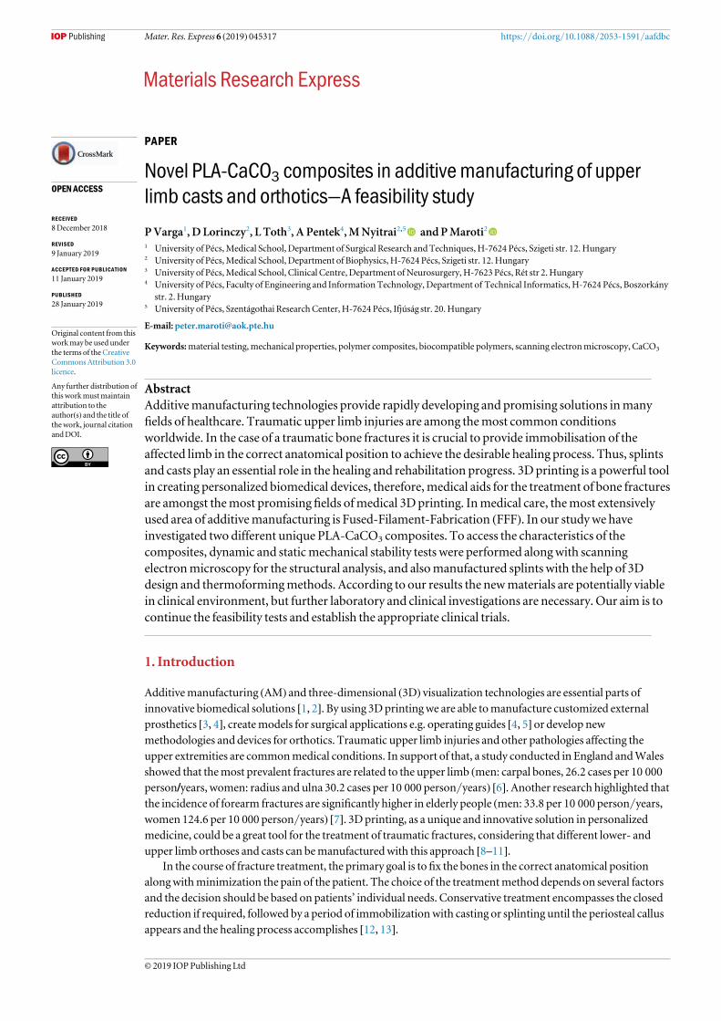
Mater. Res. Express 6 (2019) 045317 https://doi.org/10.1088/2053-1591/aafdbc
PAPER
Novel PLA-CaCO3 composites in additive manufacturing of upperlimb casts and orthotics—A feasibility study
PVarga1, D Lorinczy2, L Toth3, A Pentek4,MNyitrai2,5 andPMaroti2
1 University of Pécs,Medical School, Department of Surgical Research andTechniques,H-7624 Pécs, Szigeti str. 12.Hungary2 University of Pécs,Medical School, Department of Biophysics, H-7624 Pécs, Szigeti str. 12.Hungary3 University of Pécs,Medical School, Clinical Centre, Department ofNeurosurgery, H-7623 Pécs, Rét str 2.Hungary4 University of Pécs, Faculty of Engineering and Information Technology, Department of Technical Informatics, H-7624 Pécs, Boszorkány
str. 2.Hungary5 University of Pécs, Szentágothai ResearchCenter, H-7624 Pécs, Ifjúság str. 20.Hungary
E-mail: [email protected]
Keywords:material testing,mechanical properties, polymer composites, biocompatible polymers, scanning electronmicroscopy, CaCO3
AbstractAdditivemanufacturing technologies provide rapidly developing and promising solutions inmanyfields of healthcare. Traumatic upper limb injuries are among themost common conditionsworldwide. In the case of a traumatic bone fractures it is crucial to provide immobilisation of theaffected limb in the correct anatomical position to achieve the desirable healing process. Thus, splintsand casts play an essential role in the healing and rehabilitation progress. 3Dprinting is a powerful toolin creating personalized biomedical devices, therefore,medical aids for the treatment of bone fracturesare amongst themost promising fields ofmedical 3Dprinting. Inmedical care, themost extensivelyused area of additivemanufacturing is Fused-Filament-Fabrication (FFF). In our studywe haveinvestigated two different unique PLA-CaCO3 composites. To access the characteristics of thecomposites, dynamic and staticmechanical stability tests were performed alongwith scanningelectronmicroscopy for the structural analysis, and alsomanufactured splints with the help of 3Ddesign and thermoformingmethods. According to our results the newmaterials are potentially viablein clinical environment, but further laboratory and clinical investigations are necessary. Our aim is tocontinue the feasibility tests and establish the appropriate clinical trials.
1. Introduction
Additivemanufacturing (AM) and three-dimensional (3D) visualization technologies are essential parts ofinnovative biomedical solutions [1, 2]. By using 3Dprintingwe are able tomanufacture customized externalprosthetics [3, 4], createmodels for surgical applications e.g. operating guides [4, 5] or develop newmethodologies and devices for orthotics. Traumatic upper limb injuries and other pathologies affecting theupper extremities are commonmedical conditions. In support of that, a study conducted in England andWalesshowed that themost prevalent fractures are related to the upper limb (men: carpal bones, 26.2 cases per 10 000person/years, women: radius and ulna 30.2 cases per 10 000 person/years) [6]. Another research highlighted thatthe incidence of forearm fractures are significantly higher in elderly people (men: 33.8 per 10 000 person/years,women 124.6 per 10 000 person/years) [7]. 3Dprinting, as a unique and innovative solution in personalizedmedicine, could be a great tool for the treatment of traumatic fractures, considering that different lower- andupper limb orthoses and casts can bemanufacturedwith this approach [8–11].
In the course of fracture treatment, the primary goal is tofix the bones in the correct anatomical positionalongwithminimization the pain of the patient. The choice of the treatmentmethod depends on several factorsand the decision should be based on patients’ individual needs. Conservative treatment encompasses the closedreduction if required, followed by a period of immobilizationwith casting or splinting until the periosteal callusappears and the healing process accomplishes [12, 13].
OPEN ACCESS
RECEIVED
8December 2018
REVISED
9 January 2019
ACCEPTED FOR PUBLICATION
11 January 2019
PUBLISHED
28 January 2019
Original content from thisworkmay be used underthe terms of the CreativeCommonsAttribution 3.0licence.
Any further distribution ofthis workmustmaintainattribution to theauthor(s) and the title ofthework, journal citationandDOI.
© 2019 IOPPublishing Ltd
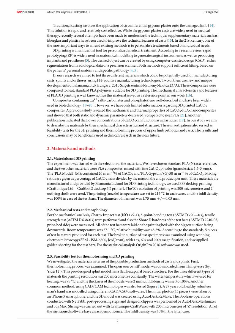
Traditional casting involves the application of circumferential gypsumplaster onto the damaged limb [14].This solution is rapid and relatively cost effective.While the gypsumplaster casts arewidely used inmedicaltherapy, recently several attempts have beenmade tomodernize the technique; supplementarymaterials such asfiberglass and plastics have been used to improve the technical features of casts [15]. In the 21st century, one ofthemost important ways to amend existingmethods is to personalise treatments based on individual needs.
3D printing is an influential tool for personalizedmedical treatment. According to a recent review, rapidprototyping (RP) is widely used in anatomicalmodelling to generate surgical instruments aswell as producingimplants and prostheses [5]. The desired object can be created by using computer-assisted design (CAD), eithersegmentation from radiological data or a precision scanner. Bothmethods support sufficient fitting, based onthe patients’ personal anatomy and specific pathology [4, 5].
In our researchwe aimed to test three differentmaterials which could be potentially used formanufacturingcasts, splints and orthoses, using FFF additivemanufacturing technologies. Two of them are new and uniquedevelopments of Filamania Ltd (Hungary, 2310 Szigetszentmiklós, Fenyőfa utca 23/A). These composites werecompared to neat, standard PLA polymers, suitable for 3Dprinting. Themechanical characteristics and featuresof PLA 3Dprinting is well known, thus thismaterial served as a reference point in ourwork [16].
Composites containingCa2+ salts (carbonates and phosphates) are well-described and have beenwidelyused in biotechnology [17–20]. However, we have only limited information regarding 3DprintedCaCO3
composites. A previous study revealed themechanical and thermal properties of CaCO3-PLA-nanocompositesand showed that both static and dynamic parameters decreased, compared to neat PLA [21]. Anotherpublication indicated that lower concentrations of CaCO3 can function as a plasticizer [17]. In our studywe aimto describe thematerials by theirmechanical characteristics and structure. These investigations also served asfeasibility tests for the 3Dprinting and thermoforming process of upper limb orthotics and casts. The results andconclusionsmay be beneficially used in clinical research in the near future.
2.Materials andmethods
2.1.Materials and 3DprintingThe experiment was startedwith the selection of thematerials.We have chosen standard PLA (N) as a reference,and the two othermaterials were PLA composites,mixedwithfineCaCO3 powder (granule size: 1.5-3 μms).The ‘PLAModell’ (M): contained 20 mm−1%ofCaCO3 and ‘PLAGypsum’ (G) 50 mm−1%ofCaCO3.Mixingratios are given as percentage of CaCO3mass divided by themass of the end product per unit. Thesematerials aremanufactured and provided by Filamania Ltd and for 3DPrinting technology, we used FFF desktop printing(Craftunique Ltd—Craftbot 2 desktop 3Dprinter). The ‘Z’ resolution of printing was 200micrometres and 2outlying shells were used. The printing (nozzle) temperature was set to 215 °C in each cases, and the infill densitywas 100% in case of the test bars. The diameter offilamentwas 1.75 mm+/− 0.05 mm.
2.2.Mechanical tests andmorphologyFor themechanical analysis, Charpy Impact test (ISO 179-1), 3-point-bending test (ASTMD790—03), tensilestrength test (ASTMD638-03)were performed and also the ShoreDhardness of the test bars (ASTMD2240-03,print-bed side)weremeasured. All of the test bars were laid on the printing bedwith the biggest surface facingdownwards. Room temperature was 27.1 °C, relative humidity was: 48.8%. According to the standards, 5 piecesof test bars were produced for each test. The broken surface of test specimenswas examined using scanningelectronmicroscopy (SEM - JSM-6300, Jeol Japan), with 15x, 60x and 200xmagnification, andwe appliedgolden sheeting for the test bars. For the statistical analysisOriginPro 2016 softwarewas used.
2.3. Feasibility test for thermoforming and 3DprintingWe investigated thematerials in terms of the possible productionmethods of casts and splints. First,thermoforming process was examined. The open source ‘.stl’model was downloaded fromThingiverse (by:‘rider12’). This pre-designed splintmodel has aflat, hexagonal based structure. For the three different types ofmaterials the printing resolutionwas 200micrometres constantly. Thewater temperaturewhichwe used forheating, was 75 °C, and the thickness of themodels were 2 mms, infill density was set to 100%.Anothercommonmethod, usingCAD/CAM technologies was also tested (figure 1). A 27 years old healthy volunteerman’s handwasmodelled using different CAD/CAMsoftwares. The initial photos (45 pieces)were taken byan iPhone 5 smart phone, and the 3Dmodel was created using AutoDeskReMake. The Boolean-operationsconductedwithNetFabb, post-processing steps and design of clippers was performed byAutoDeskMeshmixerand 3dsMax. Slicingwas carried out withCraftuniqueCraftWare, with 200 micrometres of ‘Z’ resolution. All ofthementioned software have an academic licence. The infill density was 40% in the latter case.
2
Mater. Res. Express 6 (2019) 045317 PVarga et al
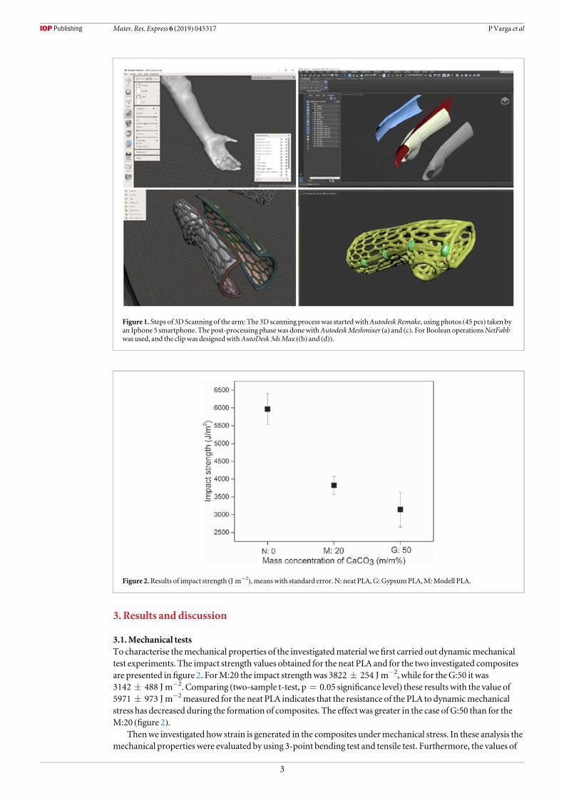
3. Results and discussion
3.1.Mechanical testsTo characterise themechanical properties of the investigatedmaterial wefirst carried out dynamicmechanicaltest experiments. The impact strength values obtained for the neat PLA and for the two investigated compositesare presented infigure 2. ForM:20 the impact strengthwas 3822±254 J m−2, while for theG:50 it was3142±488 J m−2. Comparing (two-sample t-test, p=0.05 significance level) these results with the value of5971±973 J m−2measured for the neat PLA indicates that the resistance of the PLA to dynamicmechanicalstress has decreased during the formation of composites. The effect was greater in the case of G:50 than for theM:20 (figure 2).
Thenwe investigated how strain is generated in the composites undermechanical stress. In these analysis themechanical properties were evaluated by using 3-point bending test and tensile test. Furthermore, the values of
Figure 1. Steps of 3D Scanning of the arm: The 3D scanning process was startedwithAutodesk Remake, using photos (45 pcs) taken byan Iphone 5 smartphone. The post-processing phasewas donewithAutodeskMeshmixer (a) and (c). For Boolean operationsNetFabbwas used, and the clipwas designedwithAutoDesk 3dsMax ((b) and (d)).
Figure 2.Results of impact strength (J m−2), meanswith standard error. N: neat PLA,G: GypsumPLA,M:Modell PLA.
3
Mater. Res. Express 6 (2019) 045317 PVarga et al
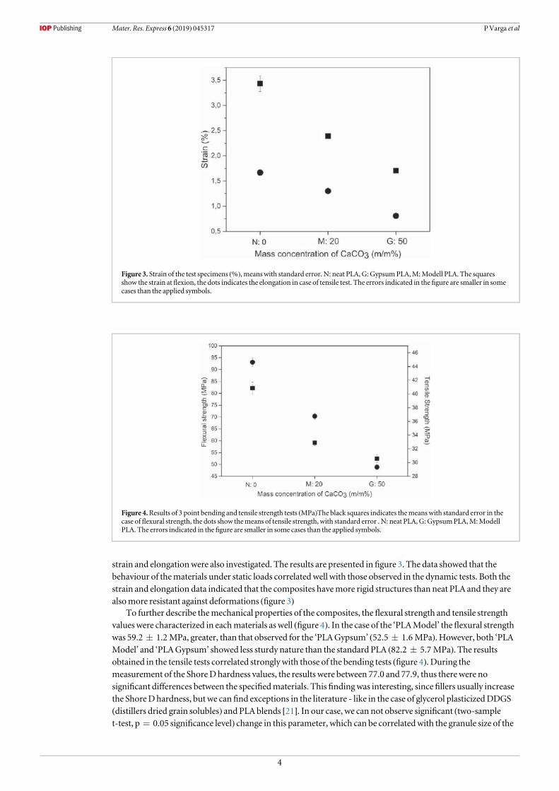
strain and elongationwere also investigated. The results are presented infigure 3. The data showed that thebehaviour of thematerials under static loads correlated well with those observed in the dynamic tests. Both thestrain and elongation data indicated that the composites havemore rigid structures than neat PLA and they arealsomore resistant against deformations (figure 3)
To further describe themechanical properties of the composites, the flexural strength and tensile strengthvalueswere characterized in eachmaterials as well (figure 4). In the case of the ‘PLAModel’ theflexural strengthwas 59.2±1.2 MPa, greater, than that observed for the ‘PLAGypsum’ (52.5±1.6 MPa). However, both ‘PLAModel’ and ‘PLAGypsum’ showed less sturdy nature than the standard PLA (82.2±5.7 MPa). The resultsobtained in the tensile tests correlated strongly with those of the bending tests (figure 4). During themeasurement of the ShoreDhardness values, the results were between 77.0 and 77.9, thus therewere nosignificant differences between the specifiedmaterials. This findingwas interesting, sincefillers usually increasethe ShoreDhardness, butwe can find exceptions in the literature - like in the case of glycerol plasticizedDDGS(distillers dried grain solubles) and PLAblends [21]. In our case, we can not observe significant (two-samplet-test, p=0.05 significance level) change in this parameter, which can be correlatedwith the granule size of the
Figure 3. Strain of the test specimens (%), meanswith standard error. N: neat PLA,G:GypsumPLA,M:Modell PLA. The squaresshow the strain atflexion, the dots indicates the elongation in case of tensile test. The errors indicated in thefigure are smaller in somecases than the applied symbols.
Figure 4.Results of 3 point bending and tensile strength tests (MPa)The black squares indicates themeanswith standard error in thecase offlexural strength, the dots show themeans of tensile strength, with standard error . N: neat PLA,G: GypsumPLA,M:ModellPLA. The errors indicated in thefigure are smaller in some cases than the applied symbols.
4
Mater. Res. Express 6 (2019) 045317 PVarga et al
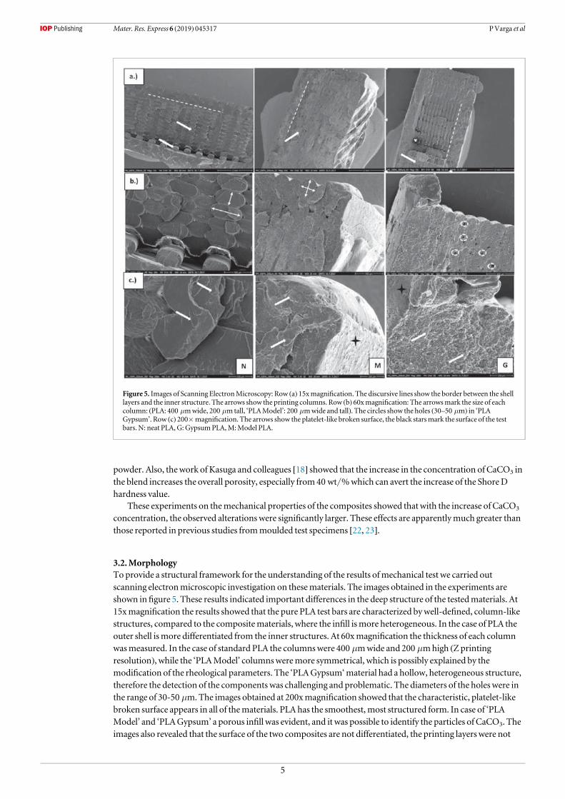
powder. Also, thework of Kasuga and colleagues [18] showed that the increase in the concentration of CaCO3 inthe blend increases the overall porosity, especially from40 wt/%which can avert the increase of the ShoreDhardness value.
These experiments on themechanical properties of the composites showed thatwith the increase of CaCO3
concentration, the observed alterationswere significantly larger. These effects are apparentlymuch greater thanthose reported in previous studies frommoulded test specimens [22, 23].
3.2.MorphologyToprovide a structural framework for the understanding of the results ofmechanical test we carried outscanning electronmicroscopic investigation on thesematerials. The images obtained in the experiments areshown infigure 5. These results indicated important differences in the deep structure of the testedmaterials. At15xmagnification the results showed that the pure PLA test bars are characterized bywell-defined, column-likestructures, compared to the compositematerials, where the infill ismore heterogeneous. In the case of PLA theouter shell ismore differentiated from the inner structures. At 60xmagnification the thickness of each columnwasmeasured. In the case of standard PLA the columnswere 400 μmwide and 200 μmhigh (Zprintingresolution), while the ‘PLAModel’ columnsweremore symmetrical, which is possibly explained by themodification of the rheological parameters. The ‘PLAGypsum‘material had a hollow, heterogeneous structure,therefore the detection of the components was challenging and problematic. The diameters of the holes were inthe range of 30-50 μm.The images obtained at 200xmagnification showed that the characteristic, platelet-likebroken surface appears in all of thematerials. PLA has the smoothest,most structured form. In case of ‘PLAModel’ and ‘PLAGypsum’ a porous infill was evident, and it was possible to identify the particles of CaCO3. Theimages also revealed that the surface of the two composites are not differentiated, the printing layers were not
Figure 5. Images of Scanning ElectronMicroscopy: Row (a) 15xmagnification. The discursive lines show the border between the shelllayers and the inner structure. The arrows show the printing columns. Row (b) 60xmagnification: The arrowsmark the size of eachcolumn: (PLA: 400 μmwide, 200 μmtall, ‘PLAModel’: 200 μmwide and tall). The circles show the holes (30–50 μm) in ‘PLAGypsum’. Row (c) 200×magnification. The arrows show the platelet-like broken surface, the black starsmark the surface of the testbars. N: neat PLA, G:GypsumPLA,M:Model PLA.
5
Mater. Res. Express 6 (2019) 045317 PVarga et al

detectable. Considering all these observations we concluded that these scanning electronmicroscopic imagesgive explanation for themechanical behaviour of the composites.
3.3. Thermoformed and 3D scannedmodels—price and timeIt is well known that PLA, as a thermoplastic polymer, can be thermoformed inwater above 70 °C, however, ithas its certain limitations. The two newmaterials are considerably simpler to form, and due to their observedrigid structure, they preserve the desired, anatomically accuratefitting position as shownonfigures 6(a) and (b).In case of the 3D scanned version the overall production timewas reasonably higher (2 h versus 19 hrespectively) and themodels costmore (average price per piece was 1.3 EUR versus 4.4 EUR respectively), butthefittingwas found to bemore precise (table 1). Furthermore, the volunteer stated that the resistance againstthe smallmovements were higher in case of using 3D scanning, he felt itmore stable, which is a key element incase of upper limb bone fractures and other pathologies. Thematerial costs for a conventional plaster casts variesaround 1–2.5 Euros, depending on the size and themanufacturer. According to these results, we can concludethat, theAM (additivemanufacturing) technology is stillmore expensive than classicalmethods, but the costsare getting closer and the differences are declining as a result of the development of newmaterials and 3Dprinters.
Figure 6. (a)Thermoformedmodels of wrist splints. N: neat PLA,G:GypsumPLA,M:Modell PLA. (b) 3D scannedmodels of wristsplints . N: neat PLA, G:GypsumPLA,M:Modell PLA.
6
Mater. Res. Express 6 (2019) 045317 PVarga et al
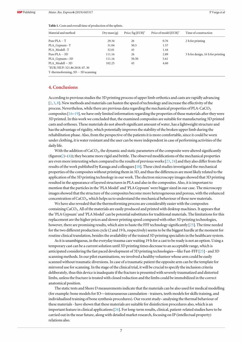
4. Conclusions
According to previous studies the 3Dprinting process of upper limb orthotics and casts are rapidly advancing[2, 3, 8]. Newmethods andmaterials can hasten the speed of technology and increase the effectivity of theprocess. Nevertheless, while there are previous data regarding themechanical properties of PLA-CaCO3
composites [16–19], we have only limited information regarding the properties of thesematerials after theywere3Dprinted. In this workwe concluded that, the examined composites are suitable formanufacturing 3Dprintedcasts and orthoses. Thesematerials do not absorb significant amount of water, has a lightweight structure andhas the advantage of rigidity, which potentially improves the stability of the broken upper limb during therehabilitation phase. Also, from the perspective of the patients it ismore comfortable, since it could bewornunder clothing, it is water resistant and the user can bemore independent in case of performing activities of thedaily life.
With the addition of CaCO3, the dynamic and static parameters of the composite were altered significantly(figures(2)–(4)); they becamemore rigid and brittle. The observedmodifications of themechanical propertiesare evenmore interesting when compared to the results of previous works [23, 24] and they also differ from theresults of thework published byKasuga and colleagues [18]. These cited studies investigated themechanicalproperties of the composites without printing them in 3D, and thus the differences aremost likely related to theapplication of the 3Dprinting technology in ourwork. The electronmicroscopy images showed that 3Dprintingresulted in the appearance of layered structures in PLA and also in the composites. Also, it is important tomention that the particles in the ‘PLAModel’ and ‘PLAGypsum’were bigger sized in our case. Themicroscopyimages showed that the structure of the composites becomemore heterogeneous and porous, with the enhancedconcentration of CaCO3, which helps us to understand themechanical behaviour of these newmaterials.
We have also revealed that the thermoforming process are considerably easier with the compositescontainingCaCO3. All of thematerials are easily produced and printedwith desktopmachines. It appears thatthe ‘PLAGypsum’ and ‘PLAModel’ can be potential substitutes for traditionalmaterials. The limitations for thisreplacement are the higher prices and slower printing speed comparedwith other 3Dprinting technologies,however, there are promising results, which aim to haste the FFF technology significantly [25]. The time neededfor the two different production cycle (2 and 19 h, respectively) seems to be the biggest hurdle at themoment forroutine clinical translation, besides the availability of the trained 3Dprinting specialists in the healthcare system.
As it is unambiguous, in the everyday trauma carewaiting 19 h for a cast to be ready is not an option. Using atemporary cast can be a current solution until 3D printing times decrease to an acceptable range, which isanticipated considering the fast paced development of 3Dprinting technologies—like Fast-FFF [25] - and 3Dscanningmethods. In our pilot examinations, we involved a healthy volunteer whose arm could be easilyscannedwithout traumatic diversions. In case of a traumatic patient the opposite arm can be the template formirrored use for scanning. In the stage of the clinical trial, it will be crucial to specify the inclusion criteriadeliberately, thus this device is inadequate if the fracture is presentedwith severely traumatized and distortedlimbs, unless the fracture is treatedwith closed reduction and the limbs could be immobilized in the correctanatomical position.
The static tests and ShoreDmeasurements indicate that thematerials can be also used formedicalmodelling(for example: bonemodels for IO—intraousseous cannulation - trainers, teethmodels for skills training, andindividualized training of bone synthesis procedures). Our recent study– analysing the thermal behaviour ofthesematerials - have shown that thesematerials are suitable for disinfection procedures also, which is animportant feature in clinical applications [26]. For long-term results, clinical, patient-related studies have to becarried out in the near future, alongwith detailedmarket research, focusing on IP (intellectual property)relations also.
Table 1.Costs and overall time of production of the splints.
Material andmethod Drymass [g] Price/kg [EUR]* Price ofmodel [EUR]* Time of construction
Pure PLA−T 29.34 26 0.76 2 h for printing
PLA_Gypsum -T 31.04 50.5 1.57
PLA_Modell - T 32.01 45 1.44
Pure PLA− 3D 111.16 26 2.89 3 h for design, 16 h for printing
PLA_Gypsum – 3D 111.16 50.50 5.61
PLA_Modell− 3D 102.25 45 4.60*EUR/HUF: 321.86 2018. 07. 30
T-thermoforming, 3D− 3D scanning
7
Mater. Res. Express 6 (2019) 045317 PVarga et al
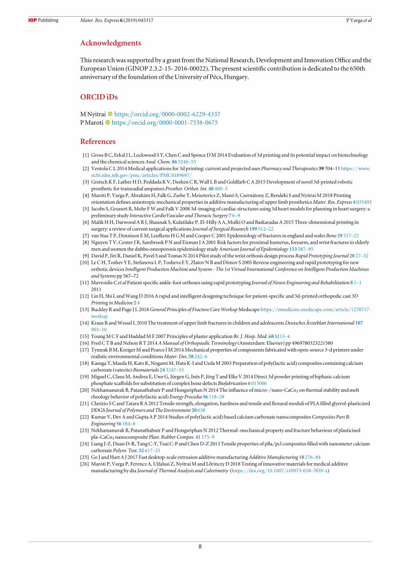
Acknowledgments
This researchwas supported by a grant from theNational Research, Development and InnovationOffice and theEuropeanUnion (GINOP2.3.2-15- 2016-00022). The present scientific contribution is dedicated to the 650thanniversary of the foundation of theUniversity of Pécs, Hungary.
ORCID iDs
MNyitrai https://orcid.org/0000-0002-6229-4337PMaroti https://orcid.org/0000-0001-7538-0675
References
[1] Gross BC, Erkal J L, Lockwood S Y,ChenC and SpenceDM2014 Evaluation of 3d printing and its potential impact on biotechnologyand the chemical sciencesAnal. Chem. 86 3240–53
[2] Ventola C L 2014Medical applications for 3d printing: current and projected usesPharmacy and Therapeutics 39 704–11 https://www.ncbi.nlm.nih.gov/pmc/articles/PMC4189697/
[3] GretschKF, LatherHD, PeddadaKV,DeekenCR,Wall L B andGoldfarbCA2015Development of novel 3d-printed roboticprosthetic for transradial amputeesProsthet. Orthot. Int. 40 400–3
[4] Maróti P, Varga P, ÁbrahámH, FalkG, Zsebe T,Meiszterics Z,Manó S, Csernátony Z, Rendeki S andNyitraiM2018 Printingorientation defines anisotropicmechanical properties in additivemanufacturing of upper limb prostheticsMater. Res. Express 4 035403
[5] Jacobs S, Grunert R,Mohr FWand FalkV 2008 3d-imaging of cardiac structures using 3d heartmodels for planning in heart surgery: apreliminary study Interactive CardioVascular andThoracic Surgery 7 6–9
[6] MalikHH,DarwoodAR J, Shaunak S, Kulatilake P, El-Hilly AA,MulkiO andBaskaradas A 2015Three-dimensional printing insurgery: a review of current surgical applications Journal of Surgical Research 199 512–22
[7] van Staa T P,Dennison EM, LeufkensHGMandCooperC 2001 Epidemiology of fractures in england andwalesBone 29 517–22[8] NguyenTV,Center J R, Sambrook PN and Eisman J A 2001Risk factors for proximal humerus, forearm, andwrist fractures in elderly
men andwomen the dubbo osteoporosis epidemiology studyAmerican Journal of Epidemiology 153 587–95[9] David P, Jiri R, Daniel K, Pavel S andTomasN 2014 Pilot study of thewrist orthosis design processRapid Prototyping Journal 20 27–32[10] LeCH, Toshev Y E, Stefanova L P, Tosheva EY, ZlatovNB andDimov S 2005Reverse engineering and rapid prototyping for new
orthotic devices Intelligent ProductionMachine and System - The 1st Virtual International Conference on Intelligent ProductionMachinesand Systems pp 567–72
[11] Mavroidis C et alPatient specific ankle-foot orthoses using rapid prototyping Journal of Neuro Engineering and Rehabilitation 8 1–12011
[12] LinH, Shi L andWangD 2016A rapid and intelligent designing technique for patient-specific and 3d-printed orthopedic cast 3DPrinting inMedicine 2 4
[13] Buckley R and Page J L 2018General Principles of Fracture CareWorkupMedscape https://emedicine.medscape.com/article/1270717-workup
[14] Kraus R andWessel L 2010The treatment of upper limb fractures in children and adolescentsDeutschesÄrzteblatt International 107903–10
[15] YoungMCF andHaddadMF2007 Principles of plaster applicationBr. J. Hosp.Med. 68M13–4[16] FredCTB andNelsonRT 2014AManual of Orthopaedic Terminology (Amsterdam: Elsevier) pp 4969780323221580[17] Tymrak BM,KreigerM and Pearce JM2014Mechanical properties of components fabricatedwith open-source 3-d printers under
realistic environmental conditionsMater. Des. 58 242–6[18] Kasuga T,MaedaH,KatoK,NogamiM,HataK-I andUedaM2003 Preparation of poly(lactic acid) composites containing calcium
carbonate (vaterite)Biomaterials 24 3247–53[19] Miguel C, ClausM,Andrea E,UweG, JürgenG, Inês P, Jörg T and ElkeV 2014Direct 3d powder printing of biphasic calcium
phosphate scaffolds for substitution of complex bone defectsBiofabrication 6 015006[20] Nekhamanurak B, Patanathabutr P andHongsriphanN2014The influence ofmicro-/nano-CaCo3 on thermal stability andmelt
rheology behavior of poly(lactic acid)Energy Procedia 56 118–28[21] Clarizio SC andTatara RA 2012Tensile strength, elongation, hardness and tensile and flexuralmoduli of PLA filled glyerol-plasticized
DDGS Journal of Polymers and The Environment 20 638[22] KumarV,DevA andGupta AP 2014 Studies of poly(lactic acid) based calcium carbonate nanocompositesComposites Part B:
Engineering 56 184–8[23] Nekhamanurak B, Patanathabutr P andHongsriphanN2012Thermal–mechanical property and fracture behaviour of plasticised
pla–CaCo3 nanocomposite Plast. Rubber Compos. 41 175–9[24] Liang J-Z, DuanD-R, TangC-Y, Tsui C-P andChenD-Z 2013Tensile properties of plla/pcl composites filledwith nanometer calcium
carbonate Polym. Test. 32 617–21[25] Go J andHart A J 2017 Fast desktop-scale extrusion additivemanufacturingAdditiveManufacturing 18 276–84[26] Maróti P, Varga P, Ferencz A,Ujfalusi Z, NyitraiM and LőrinczyD2018Testing of innovativematerials formedical additive
manufacturing by dta Journal of Thermal Analysis and Calorimetry (https://doi.org/10.1007/s10973-018-7839-x)
8
Mater. Res. Express 6 (2019) 045317 PVarga et al