Embed Size (px)
Citation preview
306IEICE TRANS. FUNDAMENTALS, VOL.E97–A, NO.1 JANUARY 2014
PAPER
Low-Power Dynamic MIMO Detection for a 4 × 4 MIMO-OFDMReceiver
Nozomi MIYAZAKI†a), Student Member, Shingo YOSHIZAWA††, Member, and Yoshikazu MIYANAGA†, Fellow
SUMMARY This paper describes low-power dynamic multiple-inputand multiple-output (MIMO) detection for a 4×4 MIMO-orthogonalfrequency-division multiplexing (MIMO-OFDM) receiver. MIMO-OFDMsystems achieve high-speed and large capacity communications. However,they impose high computational cost in MIMO detection when separat-ing spatially multiplexed signals and they consume vast amounts of power.We propose low-power dynamic MIMO detection that controls detectionspeed according to wireless environments. The power consumption is re-duced by dynamic voltage and frequency scaling (DVFS) that controls theoperating voltage and clock frequency in the MIMO detector. We imple-mented dynamic MIMO detection in a pipelined minimum mean squareerror (MMSE) MIMO detector that we developed in our previous work.A power saving of 92% was achieved under lowest clock frequency modeconditions.key words: wireless communications, MIMO detection, low power, DVFS
1. Introduction
Orthogonal frequency division multiplexing with multiple-input and multiple-output (MIMO-OFDM) is a powerfultool in enhancing communication capacities or reliance andhas widely been adopted in current wireless communicationsystems. The standardization group of IEEE802.11 wirelessLAN groups has released the IEEE 802.11n specifications[1] that are based on MIMO-OFDM technology.
MIMO detection is important in MIMO-OFDM sys-tems and needs to calculate the weight matrix in eachOFDM subcarrier from the estimates of MIMO channels.This process needs numerous matrix multiplications andinverse matrix calculations, which increase the processingtime, circuit area, and power consumption. The algorithmsfor MIMO detection are divided into linear [2], [3] and non-linear detection, such as ordered successive interferencecancellations (OSIC)[4], [5] and maximum-likelihood (ML)detection [6], [7]. There are trade-offs between MIMO de-tection and computational complexity.
Since OFDM detects MIMO channel properties on thebasis of each subcarrier, its computational cost is propor-tional to the number of subcarriers. A MIMO-OFDM re-ceiver requires considerable throughput even for linear de-
Manuscript received September 25, 2012.Manuscript revised July 31, 2013.†The authors are with the Graduate School of Information
Science and Technology, Hokkaido University, Sapporo-shi, 060-0814 Japan.††The author is with the Department of Electrical and Electronic
Engineering, Kitami Institute of Technology, Kitami-shi, 090-8507Japan.
a) E-mail: [email protected]: 10.1587/transfun.E97.A.306
tection. We focused on a hardware implementation of lin-ear detection. We previously presented a complete pipelineMMSE MIMO detector based on Strassen’s matrix inver-sion [8]. This detector can make use of concurrent andpipeline processing and has systematic matrix computationsuitable for hardware implementation. The processing timeof the complete pipeline detector is 150 times faster thanthat of other detectors [2], [3] for 512 subcarriers [8]. How-ever, it consumes large amounts of power where the powerconsumption is 701.2 mW at a 160-MHz clock frequency.
We propose low-power dynamic MIMO detection thatcontrols the detection speed according to wireless environ-ments. Our investigations indicated that the detection speedcould be controlled by maintaining communication by usingDoppler frequency information. Dynamic MIMO detectionadaptively changes the computational time in MIMO detec-tion. Power consumption is reduced by lowering the op-erating clock frequency and voltage, which is a techniquethat is known as dynamic voltage and frequency scaling(DVFS) [9], [10]. We found that dynamic MIMO detectionprovided communication quality equivalent to fixed MIMOdetection and reduced power by applying low-speed detec-tion modes. A DVFS FFT/IFFT processor that operates atadequate voltage/frequency under different MIMO config-urations has been presented [11] as a DVFS technique inMIMO-OFDM system communications. This DVFS tech-nique only treats the change in MIMO configurations anddoes not assume variations in wireless environments.
The paper is organized as follows: Sect. 2 explains analgorithm for MIMO detection in MIMO-OFDM systems.Section 3 reviews the designs of MMSE MIMO detectors,which revisits our previous work. The dynamic MIMO de-tection we propose that covers both the algorithm and circuitstructure is presented in Sect. 4. The results obtained fromevaluating communication quality and power consumptionare presented in Sect. 5. Section 6 summarizes the paper.
2. MIMO Detection Algorithm
A MIMO system that uses multiple antennas on both trans-mitter and receiver sides can increase communication ca-pacity by multiplexing and separating signals. A receivedsignal vector in a MIMO-OFDM system (i.e., multi-carrierOFDM transmission) is described by
y[k, t] = H[k]s[k, t] + n[k, t], (1)
where k indicates a subcarrier index, t indicates a data sym-
Copyright c© 2014 The Institute of Electronics, Information and Communication Engineers
MIYAZAKI et al.: LOW-POWER DYNAMIC MIMO DETECTION FOR A 4 × 4 MIMO-OFDM RECEIVER307
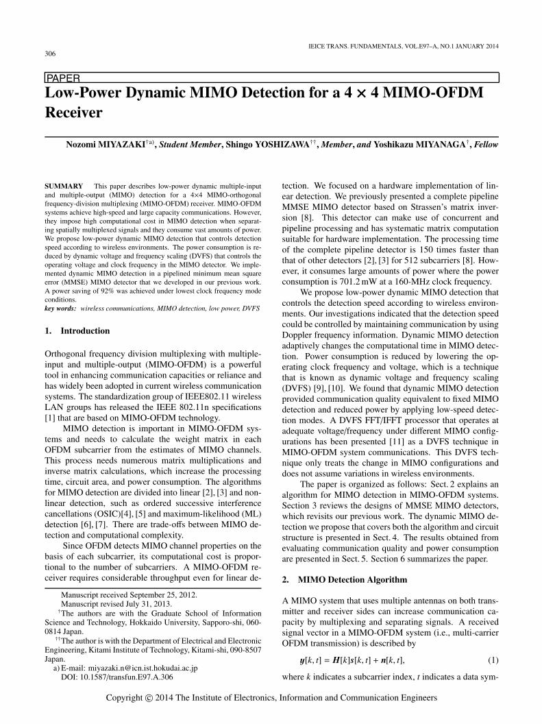
Fig. 1 Timing chart for MIMO detection.
bol index, and s[k, t] denotes a transmitted signal vector atthe t-th symbol. Here, n stands for a white Gaussian noisevector and H[k] with an MR×MT matrix indicates a MIMOchannel where MR and MT are the numbers of receiving andtransmitting antennas. Weight matrix G[k] by using the min-imum mean square error (MMSE) criterion is computed as
G[k] = (H[k]H H[k] + σ2I)−1H[k]H (2)
where (·)H denotes the complex conjugate transpose andσ2 indicates noise variance. The computation in Eq. (2) iscalled “preprocessing”. A decoded signal vector, s[k, t], isgiven by multiplying the weight matrix with the receivedsignal vector as
s[k, t] = G[k]y[k, t]. (3)
There is a timing chart for MIMO detection in Fig. 1.A MIMO detector starts computing MIMO channel matri-ces for all subcarriers when it receives the last training sym-bol. Preprocessing can be executed after each MIMO chan-nel matrix is computed. Since the data symbols follow thetraining symbols in packet mode OFDM, the detector shouldcomplete preprocessing before it receives the data symbols.Otherwise, the detector leads to unacceptable processing de-lay. We consider acceptable latency time to be the sum ofFFT duration TFFT and GI length TGI as a measure of real-time processing. For instance, the IEEE802.11n PHY framehas parameters of N=108, TFFT=3.2µs, and TGI=0.8µs,where N is the number of data subcarriers. The acceptablelatency time for preprocessing becomes 4µs.
3. Design of MMSE MIMO Detector
The circuit structure for the pipeline MMSE MIMO detectorpresented in Yoshizawa et al. [8] is briefly explained here.The pipeline MIMO detector is based on Strassen’s matrixinversion [12]. Strassen’s algorithm for matrix inversion di-vides a square matrix into four block matrices. It is dividedinto 2×2 block matrices for a 4×4 matrix Ω as
Ω =
(A BC D
), (4)
where A, B, C, and D are the 2×2 matrices. Ω−1 is calcu-lated with Strassen’s algorithm:
Ω−1 =
(F −A−1BE−1
−E−1CA−1 E−1
)
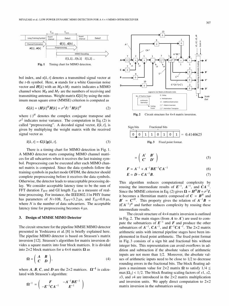
Fig. 2 Circuit structure for 4×4 matrix inversion.
Fig. 3 Fixed point format.
=
(A′ B′C′ D′
)(5)
F = A−1 + A−1BE−1CA−1 (6)
E = D − CA−1B. (7)
This algorithm reduces computational complexity byreusing the intermediate results of E−1, A−1, and CA−1.Since the MMSE criterion in Eq. (2) givesΩ = HH H+σ2I,it becomes a Hermitian matrix composed of C = BH andB′ = C′H . This property gives the relation of A−1B =(CA−1)H and further reduces complexity by reusing theseintermediate results.
The circuit structure of 4×4 matrix inversion is outlinedin Fig. 2. The main stages (from A to A′) are used to com-pute the submatrices of E−1 and F and produce the othersubmatrices of A−1, CA−1, and E−1CA−1. The 2×2 matrixarithmetic units with internal pipeline stages have been im-plemented in fixed point arithmetic. The fixed point formatin Fig. 3 consists of a sign bit and fractional bits withoutinteger bits. This representation can avoid overflows in ad-dition and subtraction if the absolute values of arithmeticinputs are not more than 1/2. Moreover, the absolute val-ues of arithmetic inputs need to be close to 1/2 to decreaserounding errors in the fractional bits. The block floating ad-justs a maximum value for 2×2 matrix Ω to satisfy 1/4 ≤max |Ωi j| < 1/2. The block floating scaling factors of s1, s2,s3, and s4 are introduced in the 2×2 matrix multiplicationand inversion units. We apply direct computation to 2×2matrix inversion in the submatrices using
308IEICE TRANS. FUNDAMENTALS, VOL.E97–A, NO.1 JANUARY 2014
Fig. 4 Structure of circuit for pipeline MMSE MIMO detector.
Table 1 Performance of circuit for pipeline MMSE MIMO detector.
Operation Frequency 160 MHzLogic Gate Count 2,203,300Pipeline Latency 187.5 nsPower Consumption 701.2 mW
ω−1 =
(a bc d
)−1
=1
ad − bc
(d −b−c a
). (8)
The circuit structure of the pipeline MMSE MIMO de-tector is outlined in Fig. 4. The inputs of H11[k] to H44[k]are elements of channel matrix H[k], and σ2 is variance inthe noise vector. The outputs of each block are computed by
P[k] = H[k]∗H[k]T + σ2I (9)
Q[k] = H[k]∗ (10)
R[k] = P−1[k] (11)
G[k] = R[k]Q[k], (12)
where S a[k], S b[k], and S c[k] are scaling factors to avoidan overflow. The pipeline delay unit adjusts computationtimings for H[k] to meet data of R[k].
The performance of the circuit for the pipeline MMSEMIMO detector is summarized in Table 1. The MIMO de-tector was implemented by using a 90-nm CMOS standardlibrary. The power consumption value was measured un-der conditions of a 1.0-V voltage supply and a 160-MHzclock speed. The implemented results indicated a satis-factory pipeline latency of 187.5 ns, which is less than theacceptable latency time of 4µs (mentioned in Sect. 2). Itrequired a large amount of power of 701.2 mW. Since theMIMO detector used about 40% of the power consumptionin the 4×4 MIMO-OFDM receiver circuit according to ourprevious work [13], the low-power technique of MIMO de-tection has a strong impact on the hardware implementationof MIMO-OFDM systems.
4. Dynamic MIMO Detection
4.1 MIMO Channel Variations
The timing chart in Fig. 1 indicates severe processing la-tency for real-time processing in a MIMO detector. Thepipeline MMSE MIMO detector has been designed to meet
Table 2 Simulation parameters.
Modulation Type 16QAMSignal Bandwith 40 MHzFFT Size 128No. of Data Subcarriers 108FFT Length 3.2µsGuard Interval Duration 0.8µsPacket Length 500 BytesChannel Model Multipath Rayleigh FadingMIMO Spatial Correlation i.i.d.Symbol Timing IdealChannel Estimation Calculation at Training SymbolsMaximum Doppler Frequency 2, 6, 10, 14, 18 HzError Correcting Convolution Coding (R=3/4)
Soft-Decision Viterbi Decoding
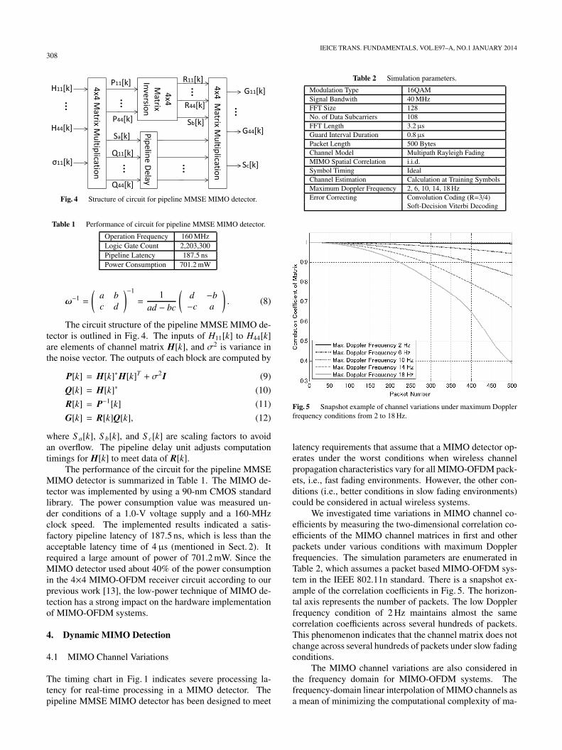
Fig. 5 Snapshot example of channel variations under maximum Dopplerfrequency conditions from 2 to 18 Hz.
latency requirements that assume that a MIMO detector op-erates under the worst conditions when wireless channelpropagation characteristics vary for all MIMO-OFDM pack-ets, i.e., fast fading environments. However, the other con-ditions (i.e., better conditions in slow fading environments)could be considered in actual wireless systems.
We investigated time variations in MIMO channel co-efficients by measuring the two-dimensional correlation co-efficients of the MIMO channel matrices in first and otherpackets under various conditions with maximum Dopplerfrequencies. The simulation parameters are enumerated inTable 2, which assumes a packet based MIMO-OFDM sys-tem in the IEEE 802.11n standard. There is a snapshot ex-ample of the correlation coefficients in Fig. 5. The horizon-tal axis represents the number of packets. The low Dopplerfrequency condition of 2 Hz maintains almost the samecorrelation coefficients across several hundreds of packets.This phenomenon indicates that the channel matrix does notchange across several hundreds of packets under slow fadingconditions.
The MIMO channel variations are also considered inthe frequency domain for MIMO-OFDM systems. Thefrequency-domain linear interpolation of MIMO channels asa mean of minimizing the computational complexity of ma-
MIYAZAKI et al.: LOW-POWER DYNAMIC MIMO DETECTION FOR A 4 × 4 MIMO-OFDM RECEIVER309
trix inversion has been presented [14]. However, the methodof interpolation needs the channel environment to be flatfading to considerably reduce complexity. Low Doppler fre-quency conditions would be more acceptable than flat fadingconditions for wireless LAN systems.
4.2 Proposed Method
Slow fading conditions do not impose severe timing con-straints on computing Eq. (2) because the channel matrix ofH changes slowly. The latency requirement in Fig. 1 couldbe loosened under slow fading conditions. We discuss dy-namic MIMO detection that adaptively changes the compu-tation time of Eq. (2) and the time intervals to update theweight matrix of G. There is a timing chart for static MIMOdetection treated as a conventional detector in Fig. 6. StaticMIMO detection computes the period of TFFT+TGI for eachpacket. The weight matrix of Gq (q is an updated index) isupdated within the same packet. The dynamic MIMO detec-tion we propose has two types of detection modes, i.e., shortand long detection delay modes, whose timing charts are inFigs. 7(a) and 7(b). The short detection delay mode extendsthe computation time to TP. TP denotes the packet lengthconsisting of training symbols and data symbols. This ex-tension means that the weight matrix is updated when thenext packet is received. The number of waiting packets Nwcontrols the frequency with which the weight matrix is up-dated. As the number of Nw increases, the number of com-putations of the weight matrix is decreased. The long de-tection delay mode further extends the computation time byNw · TP. The timing to update the weight matrix is delayed
Fig. 6 Static MIMO detection.
Fig. 7 Proposed dynamic MIMO detection.
by Nw−1 packets overall, compared with the short detectiondelay mode. The long detection delay mode is more sensi-tive to channel variations in fading environments due to thisdelay.
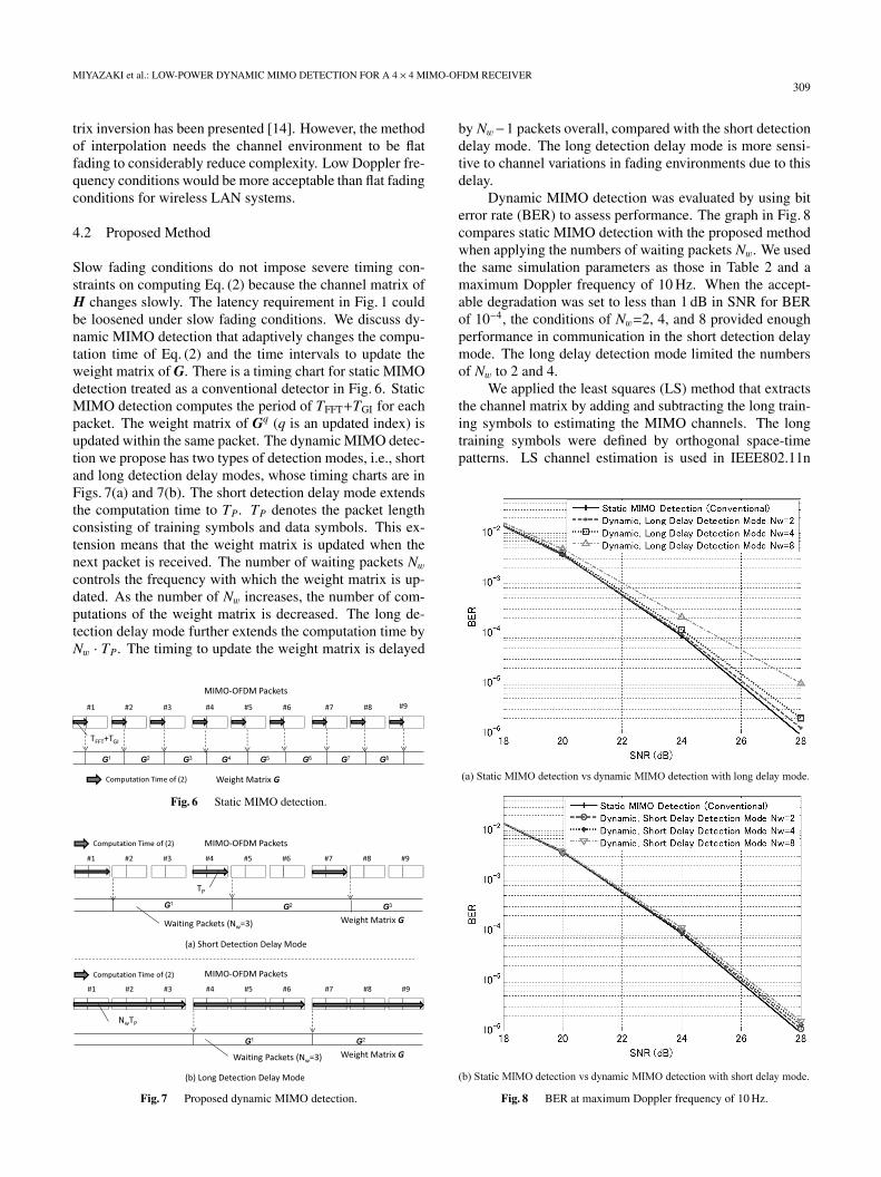
Dynamic MIMO detection was evaluated by using biterror rate (BER) to assess performance. The graph in Fig. 8compares static MIMO detection with the proposed methodwhen applying the numbers of waiting packets Nw. We usedthe same simulation parameters as those in Table 2 and amaximum Doppler frequency of 10 Hz. When the accept-able degradation was set to less than 1 dB in SNR for BERof 10−4, the conditions of Nw=2, 4, and 8 provided enoughperformance in communication in the short detection delaymode. The long delay detection mode limited the numbersof Nw to 2 and 4.
We applied the least squares (LS) method that extractsthe channel matrix by adding and subtracting the long train-ing symbols to estimating the MIMO channels. The longtraining symbols were defined by orthogonal space-timepatterns. LS channel estimation is used in IEEE802.11n
Fig. 8 BER at maximum Doppler frequency of 10 Hz.
310IEICE TRANS. FUNDAMENTALS, VOL.E97–A, NO.1 JANUARY 2014
MIMO-OFDM systems [15]. The channels are estimatedonly once to update the weight matrix. The performanceof BER would be improved by using appropriate extrapola-tion based on past channel matrices, especially in the longdelay detection mode. The power increase in this case byintroducing channel matrix extrapolation and the decreaseby increasing the number of waiting packets Nw should becompared.
4.3 Circuit Structure
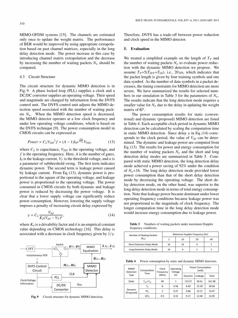
The circuit structure for dynamic MIMO detection is inFig. 9. A phase locked loop (PLL) supplies a clock and aDC/DC converter supplies an operating voltage. Their speedand magnitude are changed by information from the DVFScontrol unit. The DVFS control unit adjusts the MIMO de-tection speed associated with the number of waiting pack-ets Nw. When the MIMO detection speed is decreased,the MIMO detector operates at a low clock frequency andunder low operating voltage conditions, which is based onthe DVFS technique [9]. The power consumption model inCMOS circuits can be expressed as
Power = CLVDD2 f + (A − 1)I0e
−VTaVth VDD, (13)
where CL is capacitance, VDD is the operating voltage, andf is the operating frequency. Here, A is the number of gates,I0 is the leakage current, VT is the threshold voltage, and α isa parameter of subthreshold swing. The first term indicatesdynamic power. The second term is leakage power causedby leakage current. From Eq. (13), dynamic power is pro-portional to the square of the operating voltage, and leakagepower is proportional to the operating voltage. The powerconsumed in CMOS circuits by both dynamic and leakagepower is reduced by decreasing the power voltage. It isclear that a lower supply voltage can significantly reducepower consumption. However, lowering the supply voltageimposes a penalty of increasing circuit delay expressed by
γ = CLVdd
Kd(Vdd − VT )δ, (14)
where Kd is a drivability factor and δ is an empirical constantvalue depending on CMOS technology [16]. This delay isassociated with a decrease in clock frequency given by 1/γ.
Fig. 9 Circuit structure for dynamic MIMO detection.
Therefore, DVFS has a trade-off between power reductionand clock speed in the MIMO detector.
5. Evaluation
We treated a simplified example on the length of TP andthe number of waiting packets Nw to evaluate power reduc-tion with the dynamic MIMO detection we propose. Weassume TP=5(TFFT+TGI), i.e., 20µs, which indicates thatthe packet length is given by four training symbols and onedata symbol. As the number of data symbols in a packet de-creases, the timing constraints for MIMO detection are moresevere. We have summarized the results for selected num-bers in our simulation in Table 3 for the parameters of Nw.The results indicate that the long detection mode requires asmaller value for Nw due to the delay in updating the weightmatrix of Gq.
The power consumption results for static (conven-tional) and dynamic (proposed) MIMO detection are listedin Table 4. Each acceptable clock period in dynamic MIMOdetection can be calculated by scaling the computation timein static MIMO detection. Since delay γ in Eq. (14) corre-sponds to the clock period, the value of Vdd can be deter-mined. The dynamic and leakage power are computed fromEq. (13). The results for power and energy consumption forthe number of waiting packets Nw and the short and longdetection delay modes are summarized in Table 5. Com-pared with static MIMO detection, the long detection delaymode achieved a power saving of 92% under the conditionof Nw=16. The long delay detection mode provided lowerpower consumption than that of the short delay detectionmode by decreasing the operating voltage. The short de-lay detection mode, on the other hand, was superior to thelong delay detection mode in terms of total energy consump-tion. Note that leakage power became dominant under loweroperating frequency conditions because leakage power wasnot proportional to the magnitude of clock frequency. Thelonger computation time in the long delay detection modewould increase energy consumption due to leakage power.
Table 3 Numbers of waiting packets under maximum Dopplerfrequency conditions.
Table 4 Power consumption by static and dynamic MIMO detectors.
MIYAZAKI et al.: LOW-POWER DYNAMIC MIMO DETECTION FOR A 4 × 4 MIMO-OFDM RECEIVER311
Table 5 Summary of power and energy consumption results.
6. Conclusion
We presented dynamic MIMO detection to reduce powerconsumption in a 4×4 MIMO-OFDM receiver. DynamicMIMO detection controlled computation time in MIMO de-tection according to time-varying conditions of Doppler fre-quency. Power consumption was reduced with the DVFStechnique, which dynamically changed the clock frequencyand operating voltage. Dynamic MIMO detection reducedpower consumption to 1/14 and energy consumption to 1/17in our evaluations.
The dynamic MIMO detection we proposed assumesthat the value for Doppler frequency is known. However,estimating low Doppler frequencies as dozens of hertz re-quired long-term observations of several seconds for re-ceived signals. It was not practical to directly estimateDoppler frequency in terms of real-time processing. Ascheme of adaptive control to determine appropriate num-bers of waiting packets Nw would be more effective for time-varying wireless environments and will be discussed in fu-ture work.
References
[1] “IEEE P802.11n/D4.00: Draft amendment to wireless LAN mediaaccess control (MAC) and physical layer (PHY) specifications: En-hancements for higher throughput,” March 2008.
[2] A. Burg, S. Haene, D. Perels, P. Luethi, N. Felber, and W. Fichtner,“Algorithm and VLSI architecture for linear MMSE detection inMIMO-OFDM systems,” IEEE International Symposium on Cir-cuits and Systems (ISCAS), pp.4102–4105, May 2006.
[3] J. Eilert, D. Wu, and D. Liu, “Efficient complex matrix inversion forMIMO software defined radio,” IEEE International Symposium onCircuits and Systems (ISCAS), pp.2610–2613, May 2007.
[4] Z. Khan, T. Arslan, J.S. Thompson, and A.T. Erdogan, “Area andpower efficient VLSI architecture for computing pseudo inverseof channel matrix in a MIMO wireless system,” Proc. 19th Inter-national Conference on VLSI Design (VLSID), pp.734–737, Jan.2006.
[5] D. Perels, S. Haene, P. Luethi, A. Burg, N. Felber, W. Fichtner, andH. Bolcskei, “ASIC implementation of a MIMO-OFDM transceiverfor 192 Mbps WLANs,” 31st European Solid-State Circuits Confer-ence (ESSCIRC), pp.2152–218, Sept. 2005.
[6] S. Chen, T. Zhang, and M. Goel, “Relaxed tree search MIMO signaldetection algorithm design and VLSI implementation,” IEEE Inter-national Symposium on Circuits and Systems (ISCAS), pp.1147–1150, May 2006.
[7] B. Mennenga, E. Matus, and G. Fettweis, “Vectorization of thesphere detection algorithm,” IEEE International Symposium on Cir-cuits and Systems (ISCAS), pp.2806–2809, May 2009.
[8] S. Yoshizawa, Y. Yamauchi, and Y. Miyanaga, “VLSI implementa-tion of a complete pipeline MMSE detector for a 4×4 MIMO-OFDMreceiver,” IEICE Trans. Fundamentals, vol.E91-A no.7, pp.1757–1762, July 2008.
[9] A.P. Chandrakasan, V. Gutnik, and T. Xanthopoulos, “Data drivensignal processing: An approach for energy efficient computing,”International Symposium on Low Power Electronics and Design(ISLPED), pp.347–352, Aug. 1996.
[10] W.W. Shi, C.S. Choy, J.P. Guo, C.F. Chan, K.N. Leung, and K.P.Pun, “A 90 nm RFID tag’s baseband processor with novel PIEdecoder and uplink clock generator,” IEEE International MidwestSymposium on Circuits and Systems (MWSCAS), pp.644–647,Aug. 2010.
[11] Y. Chen, Y.-W. Lin, Y.-C. Tsao, and C.-Y. Lee, “A 2.4-Gsample/sDVFS FFT processor for MIMO OFDM communication systems,”IEEE J. Solid-State Circuits, vol.43, no.5, pp.1260–1273, May 2008.
[12] S.M. Balle and P.C. Hansen, “A Strassen type matrix inversion al-gorithm,” IOS Press, Advances in Parallel Algorithms, pp.22–30,1994.
[13] S. Yoshizawa and Y. Miyanaga, “VLSI implementation of a 4 × 4MIMO-OFDM transceiver with an 80-MHz channel bandwidth,”IEEE International Symposium on Circuits and Systems (ISCAS),pp.1743–1746, May 2009.
[14] J. Wang and B. Daneshrad, “Performance of linear interpolation-based MIMO detection for MIMO-OFDM systems,” Wireless Com-munications and Networking Conference (WCNC), vol.2, pp.981–986, March 2004.
[15] R.V. Nee, V.K. Jones, G. Awater, A.V. Zelst, J. Gardner, and G.Steele, “The 802.11n MIMO-OFDM standard for wireless LAN andbeyond,” Wireless Pers. Commun., vol.37, pp.445–453, 2006.
[16] D. Sengupta and R. Saleh, “Power-delay metrics revisited for 90 nmCMOS technology,” IEEE International Symposium on Quality ofElectronic Design (ISQED), pp.291–296, March 2005.
Nozomi Miyazaki received her B.S. fromHokkaido University, Japan in 2011. She is cur-rently studying at the Graduate School of In-formation Science and Technology of HokkaidoUniversity. Her main research interest is wire-less communication.
Shingo Yoshizawa received his B.E., M.E.,and Ph.D. from Hokkaido University, Japan in2001, 2003, and 2005. He was an AssistantProcessor at the Graduate School of Informa-tion Science and Technology of Hokkaido Uni-versity from 2006 to 2012. He is currently anAssociate Professor in Department of Electricaland Electronic Engineering at Kitami Instituteof Technology. His research interests are speechprocessing, wireless communication, and VLSIarchitecture.

312IEICE TRANS. FUNDAMENTALS, VOL.E97–A, NO.1 JANUARY 2014
Yoshikazu Miyanaga is a professor atthe Graduate School of Information Science andTechnology of Hokkaido University. He is anassociate editor of the Journal of Signal Process-ing, RISP Japan (2005-present). He was chairof the Technical Group on Smart Info-MediaSystems, IEICE (IEICE TGSIS) (2004–2006),and he is now a member of the IEICE TGSISadvisory committee (2006-present). He is alsoa vice-President of the IEICE Engineering Sci-ence (ES) Society. He is a fellow member of
IEICE. In addition, he is a vice-President of the Asia-Pacific Signal and In-formation Processing Association (APSIPA). He was a distinguished lec-turer (DL) of the IEEE CAS Society (2010–2011) and he is now on theBoard of Governors (BoGs) of the IEEE CAS Society (2011-present).


![Demanslarppt [Uyumluluk Modu] · PDF fileAlzheimer Hastalığında Kognitif Seyir: 21. KISA MENTAL DURUM MUAYENE SORGULAMASI ( MMSE -MMT) 22. 23. EVRE -MMSE:](https://img.pdfslide.tips/doc/110x75/5a733cee7f8b9aa7538e6030/demanslarppt-uyumluluk-modu-alzheimer-hastaliginda-kognitif-seyir-21.jpg)