Embed Size (px)
Citation preview

Construction of cERL Cryomodulesfor Injector and Main Linac
Members for ERL Main linac
K Umemori T Furuya H Sakai (KEK)K. Umemori, T. Furuya, H, Sakai (KEK),
K. Shinoe (ISSP, University of Tokyo),
M. Sawamura (JAEA-ERL),
E. Cenni (Sokendai)
Members for ERL Injector linacE. Kako, S. Noguchi, M. Satoh, T. Shishido,
K Watanabe Y Yamamoto (KEK)K. Watanabe, Y. Yamamoto (KEK)
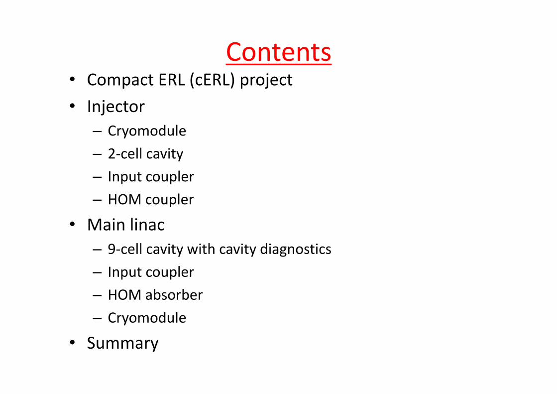
Contents• Compact ERL (cERL) project
• Injector• Injector– Cryomodule
2 cell cavity– 2‐cell cavity
– Input coupler
HOM coupler– HOM coupler
• Main linac– 9‐cell cavity with cavity diagnostics
– Input coupler
– HOM absorber
– Cryomodule
• Summary

The Compact ERL(cERL) for demonstrating ERL technologies
Before constructing large‐scale ERL facility, we need to demonstrate the generation of ultra‐low emittance beams using key devices.
Compact ERL
Parameters of the Compact ERL
beams using key devices.
ParametersBeam energy 35 - 245 MeVInjection energy 5 MeV ERL Test Facilityj gyAverage current 10 - 100 mAAcc. gradient (main linac)
15 MV/m(main linac)Normalized emittance
0.1 - 1 mm·mrad
Bunch length 1 3 ps (usual)Bunch length(rms)
1 - 3 ps (usual)~ 100 fs (with
B.C.)RF frequency 1 3 GHz
3
RF frequency 1.3 GHz
100 m
※ blue numbers are parameters for initial stage

Current status of ERL Test Facility300 kW klystrony
30 kW klystron and IOTy
2K refrigerator system
ERL Test Facility from top of pcleanroom
Cleanroom for module assembly
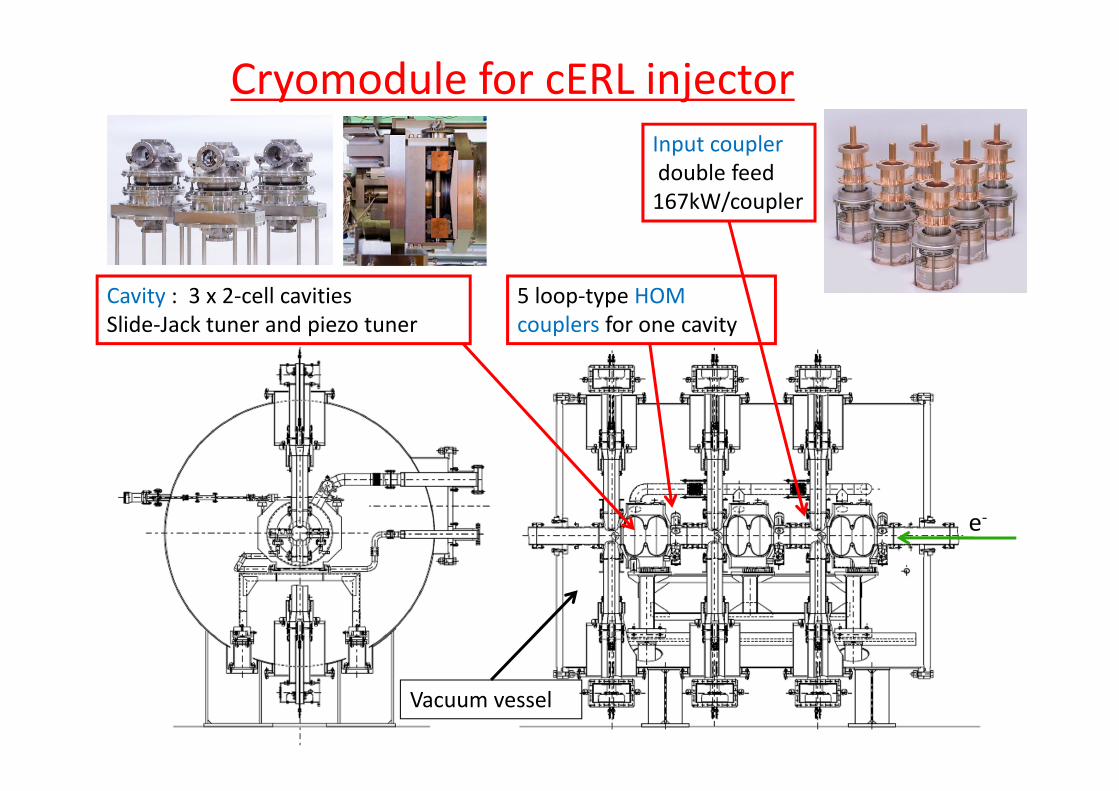
Cryomodule for cERL injectorInput couplerdouble feed167kW/coupler
Cavity : 3 x 2‐cell cavities 5 loop‐type HOM ySlide‐Jack tuner and piezo tuner
p ypcouplers for one cavity
e‐
Vacuum vessel
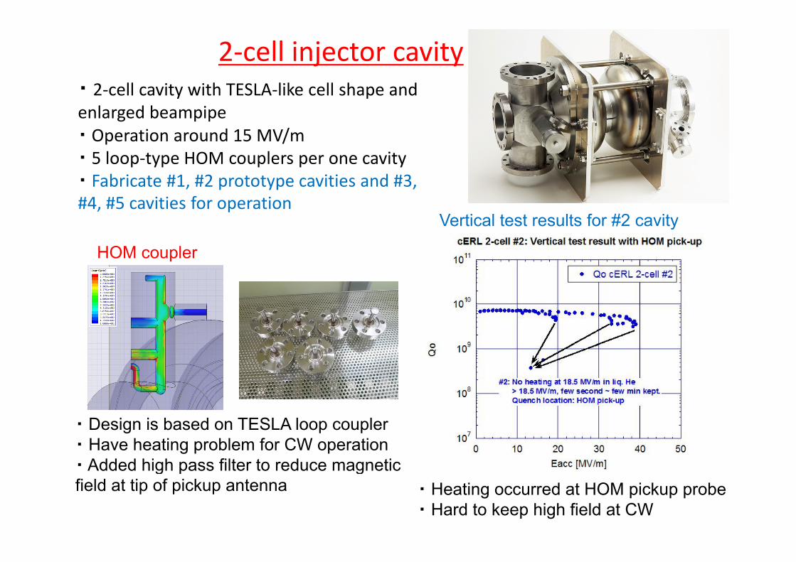
2‐cell injector cavity・ 2 cell cavity with TESLA like cell shape and2‐cell cavity with TESLA‐like cell shape and enlarged beampipe ・ Operation around 15 MV/m5 l t HOM l it・ 5 loop‐type HOM couplers per one cavity
・ Fabricate #1, #2 prototype cavities and #3, #4, #5 cavities for operation
Vertical test results for #2 cavityVertical test results for #2 cavity
HOM coupler
・ Design is based on TESLA loop coupler・ Have heating problem for CW operation・ Added high pass filter to reduce magnetic
・ Heating occurred at HOM pickup probe・ Hard to keep high field at CW
g p gfield at tip of pickup antenna

Cooling of HOM coupler and cavity #3 VT results
Setup of vertical test for 2-cell cavityfor 2 cell cavity
• Field could be kept to be > 25 MV/m at CW, with the condition HOM coupler Enhanced cooling of HOM pickup
Th l h d HOM i k was out of He.Enough for CW use of cERL.
・ Thermal anchor around HOM pickup connector.・ Thermal connection of antenna was improved using Indium seal F th li t d i iimproved using Indium seal.・ Polish antenna surface
• Further cooling study is on going• Some R&Ds are going for feedthrough
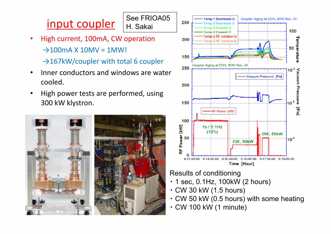
input coupler• High current 100mA CW operation
See FRIOA05 H. Sakai
• High current, 100mA, CW operation
→100mA X 10MV = 1MW!
→167kW/coupler with total 6 coupler→ / p p
• Inner conductors and windows are water cooled.
h f d• High power tests are performed, using 300 kW klystron.
Results of conditioning・ 1 sec, 0.1Hz, 100kW (2 hours)・ CW 30 kW (1.5 hours)
CW 50 kW (0 5 h ) ith h ti・ CW 50 kW (0.5 hours) with some heating・ CW 100 kW (1 minute)
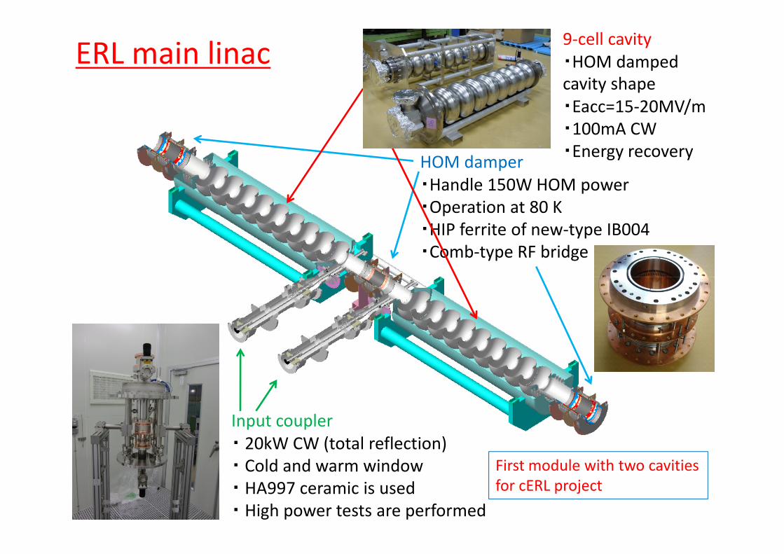
ERL main linac 9‐cell cavity・HOM damped cavity shapecavity shape・Eacc=15‐20MV/m・100mA CW・Energy recovery
HOM damper・Handle 150W HOM power・Operation at 80 K
・Energy recovery
p・HIP ferrite of new‐type IB004・Comb‐type RF bridge
Input coupler・ 20kW CW (total reflection)・ Cold and warm window First module with two cavities・ Cold and warm window・ HA997 ceramic is used・ High power tests are performed
First module with two cavitiesfor cERL project

Results of vertical testsSee posterTHPO034 E. Cenni
#1 ERL 9‐cell cavity 1e+011
ERL 9cell #1 9th7th5th
#2 ERL 9‐cell cavity (With Ti endplate, stiffener ring, NbTi flanges)
1e+011ERL 9cell #2 3rdERL 9cell #2 2nd
1e+009
1e+010
Qo
7th5th4th3rd2nd1st
1e+009
1e+010
Qo
ERL 9cell #2 2ndERL 9cell #2 1st
1e+008
1e+009
0 5 10 15 20 25 30 35
Eacc [MV/m]
1e+008
1e+009
0 5 10 15 20 25 30
Eacc [MV/m]Eacc [MV/m]
・ Severe field emissions were observed・Maximum Eacc was limited to 15 ~ 17
・ Can reach to > 20 MV/m for both tests・ Field emissions were not so large
Eacc [MV/m]
MV/m, until 8th measurements.・At last, we got nice results, > 20 MV/m at 9th measurements.
Field emissions were not so large
# low Q value is due to SUS flanges, used after 5th measurement of #1 cavity# low Q value #2 cavity 2nd VT was recovered at 3rd VT, by just warming-up

Cavity diagnostics・ Array of Si diode for X-ray detection and carbon resistor for temperatureand carbon resistor for temperature measurement・ They will rotate around cavity by using pulse motor
1e+010
1e+011
Qo
ERL 9cell #2 3rdERL 9cell #2 2ndERL 9cell #2 1st
using pulse motor
1e+008
1e+009
0 5 10 15 20 25 30
Eacc [MV/m]
3rd VT for #2 cavity initial pi-mode (23MV/m)
X-ray mapping[ d t f 1 3 ll ]
Temperature mapping[ d t f 1 3 ll ])[no data for 1-3 cells] [no data for 1-3 cells]
out
put(V
)
∆T(
K)
50° 7 ll 50° 7 ll
150°4cell 150°4cell P
IN
∆50° 7cell
200° 6cell
50° 7cell
200° 6cell
150°

T‐mapping (π‐mode, 23 MV/m) X‐ray mapping (π‐mode, 23 MV/m)
7 ll 50°d t7cell 50°down part
Observed X-ray trace and also temperature rise at same position!
Eacc vs Delta T (pi‐mode 2nd) (50deg) (7cell & 8cell)Temperature rise at quench (#2 cavity, 3rd VT, π‐mode, >25MV/m)
expand7cell
expandQuench occur at down part of 7cell
Quench due to field emission was detected

• Basic parameters
Development of input coupler for main linacBasic design
W i dCold window
See TUPO005, FRIOA05 H. Sakai
frequency : CW, 1.3GHzAccelerating gradient : Max 20MV/m
input power:max 20kW , standing wave
loaded Q(Q ): (1‐4) * 107 (variable coupling)
Warm windowvacuumCold window
N2 gascooling
cavity
loaded Q(QL): (1‐4) 10 (variable coupling)• Points
Forced N2 gas cooling of inner conductor
Impedance 60Ω bellows99.7% pulity of ceramic window are used.
RF power80K5K
・High power test of prototype of input coupler under liquid Nitrogen cooling with vacuum insulator g p p yp p p q g gCan keep 20kW power for 16hours with standing wave.Finally achieve 25kW power feeding with standing wave.
Vacuum insulator
Results of keeping 20kWWarm windowLiq. N2 tank
30kW IOT
circulator
High power test setup with liquid Nitrogen Cold window
Prototype of input coupler
Input couler
Sudden power down is mainly Caused by noise of arc sensor.
Doorknob exchanger

HOM absorber ・HIP ferrite of new‐type IB004・Comb‐type RF bridge
Cooling test at 80K HOM measurement at RT
See posterTUPO003 M.Sawamura
Cooling test at 80K (using prototype without ferrite)
HOM measurement at RT(using prototype with ferrite)
・ Cooling ability against 100W HOMs was tested 100W HOMs was tested under 80K condition.・ Generally, it went well.・ Modification for C b h t d
H t l t t (RT 80K)
Comb-shape to reduce thermal transmission.
0Dipole Dipole Dipole Dipole
Monopole Monopole
0Dipole Dipole Dipole Dipole
Monopole Monopole
Heat cycle test (RT – 80K)(using prototype with ferrite)
-80
-60
-40
-20
w_HIPwo HIP
S21
(dB
)
-80
-60
-40
-20
w_HIPwo HIP
S21
(dB
)
-100wo_HIP
103
104
105
w_HIPwo_HIP
Load
ed Q
-100wo_HIP
103
104
105
w_HIPwo_HIP
Load
ed Q
• Heat cycles between RT to 80K were ・ Mounted on LBP side of #2 cavity
102
1400 1600 1800 2000 2200 2400 2600 2800Frequency (MHz)
102
1400 1600 1800 2000 2200 2400 2600 2800Frequency (MHz)
• Heat cycles, between RT to 80K, were applied to prototype HOM absorber.• Some cracks were observed• Details are under inspection
・ Mounted on LBP side of #2 cavity, and measured at room temperature・ HOMs are sufficiently damped.
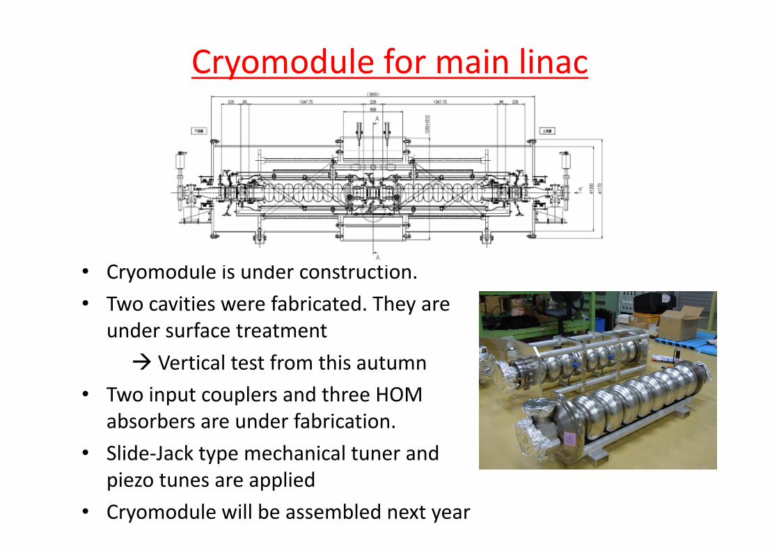
Cryomodule for main linac
• Cryomodule is under constructionCryomodule is under construction.
• Two cavities were fabricated. They are under surface treatment
Vertical test from this autumn• Two input couplers and three HOMTwo input couplers and three HOM
absorbers are under fabrication.
• Slide‐Jack type mechanical tuner and yppiezo tunes are applied
• Cryomodule will be assembled next year
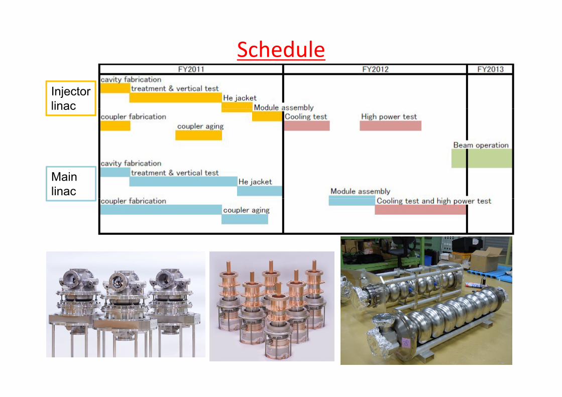
Schedule
Injector linaclinac
Main linac

Summary• cERL is under construction at ERL Test Facility in KEK.
• Injector linac• Injector linac– Cavity is ready. Heating problem at HOM pickup was improved and > 25 MV/m was achieved for CW operationimproved and > 25 MV/m was achieved for CW operation.
– Input coupler successfully passed 50 kW of CW power. For 100 kW and more, cooling should be improved., g p
• Main linac– Cavity reached to > 20 MV/m– Cavity reached to > 20 MV/m
– Input coupler passed > 20 kW standing wave.
Several tests were done for HOM absorber– Several tests were done for HOM absorber.
• Both cryomodules will be constructed during 2012. Aft li t t d hi h t t bAfter cooling test and high power test, beam operation will start.

Please join to ERL2011, which will be held at Tsukuba, October 16-21