Embed Size (px)
Citation preview

- 267 - Underlying Technology / Vessel-In Vessel / Remote Handling
UT-VIV/AM-ECIr Task Title: REMOTE HANDLING TECHNIQUES Radiation effects on electronic components INTRODUCTION The well-known method commonly named “carrier current principle”, often implemented on consumer applications (home control instrumentation using electrical nets, data transfer using phone nets) has also proven its capacity for data exchange in severe environments and wires number limitations protocols. Some experiments of this method were conducted a few years ago to control embedded video camera parameters inside low-dose level cells [1]. A more recent development concerned an absolute position encoder readings involved on hot cells cranes driving [2]. 2004 works focus on the availability to apply these realizations to a more complex situation such as encountered with remote control of maintenance tools of ITER and high level of temperature and radiation. The present document first describes the main points of the previous experiments. Then, the design of a new mock-up is presented as well as laboratory tests and temperature experiments. 2004 ACTIVITIES BRIEF “STATE OF THE ART” STUDY To increase the quality of the images of objects situated inside reprocessing cells, acquired by an embedded video camera, some parameters were remotely controlled using supply wires (easier than video cable). The scheme represented on figure 1 shows a full data link using carrier current transmission between an emitter, which frames digital data and insert them in the supply link, and a receiver which extracts the frame from the global signal received on the supply link, but also reconstitutes supply voltage for its inner electronic modules.
C C
L L
UDC UDC
UAC UAC
UAC + UAC
RC
RT
Figure 1 : Basic principles of carrier current transmission
The emitter, in this project a Man-Machine Interface, regularly generates (4 ms) a 16 bits frame based on operator requirements for the embedded parameters. For those very simple and slow dialogs, the high level duration of a reference digital signal is modulated to assume the coding of “0” and “1” binary digits, which avoids the inclusion of an independent clock signal. The digital signal is then sent to the FSK system (Frequency Shift Keying) to be converted into an analog signal UAC (one frequency for each of the two digital levels). This last signal is mixed with the supply signal, UDC, through solenoids and capacitors and sent as UDC+UAC on the bifilar support to the receiver. The receiver, an embedded electronic module of the camera, separates UAC+UDC. UDC is necessary for all supply voltages and data are extracted from UAC to activate the necessary functions. The expected low dose environment (less than 2 kGy) enabled us to report FSK modulation and demodulation on dedicated integrated components XR-2211 and XR-2206 which delivers a precise continuous phase shifting.
Figure 2 : Full experimental mock-up The full mock-up test bench, presented on figure 2 was experimented under radiation with on-line measurements up to 2 kGy. No failures were observed during the irradiation period. Some chronograms registered during the experiment. On figure 3, GENE and DEMODU curves show the nominal frame generated by the MMI module and the finale frame issued from the demodulator. CLK curve is generated from the rising fronts of the received signal and reconstituted to deliver a usual clock signal. This signal is then used to transfer the frame to buffers and, later, sensors and actuators of the camera.
MMI for the generation of the frame (UAC)
Supply (UDC)
Embedded module
One cable for UDC+UAC

- 268 - Underlying Technology / Vessel-In Vessel / Remote Handling
Figure 3 : Chronograms registered
during experimental tests The second development was needed for on-cell encoders readings expected to encounter total dose over 100 kGy which can not be solved by components such as those selected above. The solution was firstly to define and design a “discrete” modulation/demodulation system using proprietary oscillators and switching mechanisms.
Oscillator using quartz
Switching mechanism
Filtering
Gain
Data to be sent
Figure 4 : Modulation module with discrete components
The electronic functions of the modulation modules are represented on figure 4. The two chosen frequencies (F1 5.5 MHz for high level “1” and F2 1.3 MHz for low level “0”) are defined through a common 11 MHz quartz oscillator and some logic components. Then, two filters centred on each frequency convert square logic signals to their analog sinusoidal form while eliminating secondary harmonics. The last gain stage assumes summation of the two sinusoidal signals and delivers the FSK modulated signal. Demodulation must be done with care. To reduce the number of wires, it is not possible to transfer FSK frequencies between modules. These signals must be locally reconstituted or retrieved through FSK signals with adapted filters.
Filtering Détection
Comparaison
FSK signal
Level «1»
Figure 5 : Demodulation of “1” logic level frequency
Typically, in figure 5, a 2nd order Sallen-Key cell band pass filter with 5.5 MHz central frequency provides the FSK modulated “1” signal. The detection cell with a diode and RC components ensures a correct peak detection of the modulation signal F1 without significant unwanted effect during the null signal time. Based on these operational electronic modules, a full duplex transmission using a single wire was realised with a OOK (On-Off keying) modulation for each way (only one level is translated into sinusoidal signals, the other being set to ground).
Figure 6 : Mod/demod of a clock signal Laboratory tests of the line transmission made with a common clock signal sent to each modulator (F1 or F2 FSK frequencies), gives, after demodulation on each side, signals which are similar to the initial ones (see figure 6). For this experiment, most components were issued from radiation tolerance tests. ON-GOING DEVELOPMENTS The developments of a full carrier current link with both data and supply, available under high temperature and dose environments, are initiated by the remotely handled camera development with most of the techniques proposed by the second example to mitigate the lack of FSK integrated circuits. Some of the results coming from fusion tasks [3] [4] were also kept to actualise the design of the mock-up with components robust to high level of radiation and temperature. Then, the FSK frequencies are limited by the bandwidth of the OPA27/OPA277 needed for these sub-modules. A reasonable agreement could be a high value of about 300 kHz. Starting with a clock signal issued of a 4MHz quartz, the signal was derived through simple AUC flip-flops up to reach the two FSK frequencies signals of 250 kHz (logic “1” level) and 125 kHz (logic “0” level).
Common clock signal
After mod/demod on one way
After mod/demod on the other way
- 269 - Underlying Technology / Vessel-In Vessel / Remote Handling
Figure 7 : Pass band 2nd order filter These two signals are sent to a simple AUC logic switching mechanism to be separated and clocked on the data signal input. A simple passive 2nd order pass band filter is used (see figure 7) on each branch to generate the corresponding FSK sinusoidal signals. Then these two analog signals are added to deliver the full FSK data signal as represented on figure 8.
Figure 8 : FSK modulation and data signals ADAPTATION TO THE SUPPLY LINE A positive +7.5V supply and a negative –7.5V is applied to the mock-up. By itself, the modulated signal cannot drive the positive supply line for carrier current transmission. A push-pull power amplifier is associated with an OPA mounted to control the switching distortion. It delivers enough current to attack and modulate the supply line voltage. The adaptation to the line is realised by a simple filter cell inserted at each end of the line (here, a 10 meters twisted pair of wires). The C4 capacitor of figure 9 avoids continuous supply current to enter the FSK modules while the inductance avoids FSK modulation current to perturb the continuous supply. At the end of the line, the FSK modulated signal is extracted while the supply signal is set free for applications (symbolised by the load point). No further development was made to precisely define the values of the cell.
FSKModulation
FSKdemodulation
LOAD Supplyline
+
FSK signals
FSKModulation
FSKModulation
FSKdemodulation
LOAD Supplyline
+
FSK signals
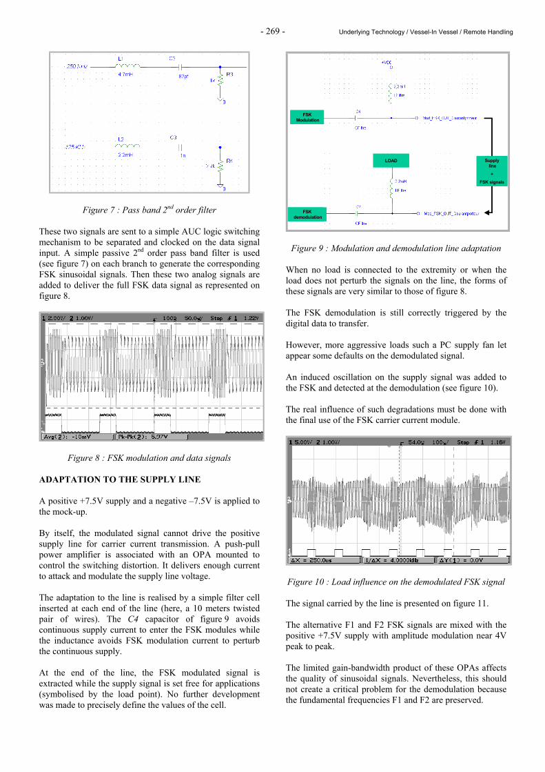
Figure 9 : Modulation and demodulation line adaptation When no load is connected to the extremity or when the load does not perturb the signals on the line, the forms of these signals are very similar to those of figure 8. The FSK demodulation is still correctly triggered by the digital data to transfer. However, more aggressive loads such a PC supply fan let appear some defaults on the demodulated signal. An induced oscillation on the supply signal was added to the FSK and detected at the demodulation (see figure 10). The real influence of such degradations must be done with the final use of the FSK carrier current module.
Figure 10 : Load influence on the demodulated FSK signal The signal carried by the line is presented on figure 11. The alternative F1 and F2 FSK signals are mixed with the positive +7.5V supply with amplitude modulation near 4V peak to peak. The limited gain-bandwidth product of these OPAs affects the quality of sinusoidal signals. Nevertheless, this should not create a critical problem for the demodulation because the fundamental frequencies F1 and F2 are preserved.

- 270 - Underlying Technology / Vessel-In Vessel / Remote Handling
Figure 11 : Evolution of signal on the 10 m line Care should be made to verify that the additional spectrum created by the AOP limitation does not interfere with others signals on the supply line. It should also be possible to exchange OPAs with better ones like AD711 with the restriction of a non certified very high total dose tolerance. The remaining of the work was done, when needed, with these components. The mock-up developped to validate FSK and carrier current supply principles is presented on figure 12. The driving of an embedded sensor, like LVDT position encoder, needs some new modules validated on some of ITER functions [5].
Figure 12 : Test bed to validate FSK and carrier current supply
ADAPTATION TO THE FLOATING GROUND SUPPLY To supply the sensor with a single wire, it is necessary to replace external double supplies by an embedded floating ground supply able to deliver +/-7.5V from external 15V. The study conducted under RADTOL developments was modified in order to take into account carrier current developments as detailed on figure 13.
Figure 13 : Floating ground and carrier current association
No significant problems were occurred to realise the adaptation of the two developments. A load current of about 200 mA did not affect the stability of the internal supplies (+/-7.5V) and the FSK signals. The different registered signals on figure 14 show the correct evolution of the FSK signals from modulation to demodulation via the supply line.
Figure 14 : Chronograms of FSK signals PWM CODING As for the remote control of the camera, the clock management must be integrated within the transmitted signal in order to limit wires number. Associated with FSK modulation and relatively slow frame communications, the coding of binary digits as duration of a clock base signal to deliver is very simple and useful (see figure 15).
Figure 15 : PWM coding The robustness to dose effects of most of the necessary components enables to define, starting from FSK timers, an efficient additional logic module able to convert data to
Floating ground supply
Embedded sensor
Demodulated FSK signal
FSK signal on the line
Data signal
Mock-up Transmission
line
Demodulation module

- 271 - Underlying Technology / Vessel-In Vessel / Remote Handling
data PWM (see figure 15), that last data becoming the input of FSK modulation. The resulting chronograms are shown on figure 16.
Figure 16 : PWM and FSK modulation The full demodulation module, also achieved, provides, on figure 17, an operational full data transmission link based on FSK and carrier current principles with a particular PWM coding used to allow clock transfer without any extra wire. The drift observed is mostly inherent to the intermediate stages and can be easily optimised.
Figure 17 : Full carrier current data link transmission TEMPERATURE VALIDATION The full mock-up was validated up to 150°C with on-line control during long term periods and short stresses without any major incidents or failures. The signals showed a regular stability as can be seen on figure 17. CONCLUSION Works done during this year carried a very simple and robust link to transfer with a medium rate, data from a sensor to a remote control desk. The advanced limitation of wires with embedded supplies and clock masking could offer some answers for data consultings in very severe environments. The volontaire approach based on previous developments for nuclear activities should be seen also as a logical come back to perform them with emerging technologies and higher performance.
Figure 18 : Full mock-up inside oven REPORTS AND PUBLICATIONS [1] Michel Robiolle - Télécommande de cameras - Report
CEA/DRT/LIST/DTSI/SLA/02-83. [2] Julien Coudon - Réalisation d’une transmission de
type modulation FSK en environnement durci - internal report.
[3] Fusion Technology Annual Report 2003 EURATOM
CEA pp 113-117. [4] Fusion Technology Annual Report 2002. [5] Fusion Technology Annual Report 2004. TASK LEADER Alain GIRAUD DRT/LIST/DTSI/SARC/LCSD CEA-Saclay F-91191 Gif-sur-Yvette Cedex Tél. : 33 1 69 08 64 30 Fax : 33 1 69 08 20 82 E-mail : [email protected]
Clock base
PWM frame « 101 » coding
FSK + PWM frame « 101 » coding
Nominal « 101 » data
Received « 101 » data

- 272 - Underlying Technology / Vessel-In Vessel / Remote Handling

- 273 - Underlying Technology / Vessel-In Vessel / Remote Handling
UT-VIV/AM-Hydro Task Title: TECHNOLOGIES AND CONTROL FOR REMOTE HANDLING
SYSTEMS INTRODUCTION CEA in collaboration with CYBERNETIX and IFREMER has developed the advanced hydraulic robot MAESTRO. Control laws developed in the TAO 2000 controller made possible the use of the MAESTRO in a force reflective master-slave configuration. Development around the actuating technology of the MAESTRO’s hydraulic arm successfully proved on servo-valves prototypes the interest to use pressure control servo-valve instead of flow control servo-valve. The control is directly made on the pressure, i.e. the force which makes real improvement during force control modes which are extensively used in remote handling techniques. In-LHC (French servo-valve manufacturer), developed a pressure servo-valve prototype that fits the MAESTRO’s space constraints. Operating in a fusion reactor requires a cleanliness level that oil hydraulic cannot ensure. Pure water hydraulics therefore proposes a good alternative and developments are today focusing in that direction. Although basic hydraulic elements like pumps, valves, filters running with pure water are already available on the market, the number of actuation means like servo-valves is very low. The existing products are big, their design was sometimes quickly adapted to water without real endurance tests and their reliability steel needs to be tested. Collaboration between CEA and In-LHC was started to evaluate the feasibility to accommodate the existing design of the oil pressure control servo-valve to a prototype running with water. 2004 ACTIVITIES NEW CONSIDERATIONS DUE TO WATER USE New interactions between hydraulic components and the fluid are to be considered when an oil-designed component has to be used with water. The list below gives some of the main identified area of improvement: Corrosion, erosion, cavitation, scale deposit, temperature influence, pH influence, viscosity, bulk modulus, poor lubrication, and long lasting stops of the hydraulic system. Materials of the servovalve are adapted to reduce the effect of corrosion.
A good balance must be found between materials providing good corrosion resistance but low hardness compared to that required in the main elements of the valve. Coatings are sometimes providing a good answer but surface roughness also play a major role in the development of corrosion. Reduction of the effects of water can be expected with modifications of the design. An improved design can reduce the effect of low viscosity, cavitation and casket corrosion. Modifications will focus on: - Reduction of clearances. - Avoid sudden section widening. - Introduction of a sleeve in the valve body. NUMERICAL MODELS OF THE SERVOVALVE The Experimental feedback gained on operations with the oil version of the pressure control servo-valve developed for the Maestro manipulator can provide helpful information for the design of the water servo-valve. According to In-LHC’s know-how, a 1D model of the oil version of the pressure control servo-valve was built in the AMESIM software. The two stages of the valve are described: - The pilot stage with the torque motor, and the flapper
nozzle assembly. - The power stage composed of the spool and main body
of the valve. The model takes into account: - The fluid properties:
. density,
. viscosity,
. bulk modulus
. … - The geometry of the valve:
. ports diameters,
. pressure losses,
. clearances,
. … Parameters of the model were fitted according to the experimental results of the oil servo-valve. Fluid parameters were then modified to evaluate the behaviour of the water version. Analysis of the 1D model provided information on the: - Pressure gain - Internal leaks - Flow response for a given pressure step - Dynamic response

- 274 - Underlying Technology / Vessel-In Vessel / Remote Handling
After tuning, estimations of the servovalve behaviour is summarized in the figure 1 to figure 3.
Figure 1 : Computed pressure gain of the water servovalve
Figure 2 : Computed leaks of the water servovalve
Figure 3 : Computed dynamic response
Compared to oil, the saturation pressure of water is very low and it is necessary to check that cavitation can not occur in local areas with high pressure drops. The ports and nozzle areas are considered to be zones with high cavitation risk. 3D flows can be modeled in the FloWorks software. A local model of the port area was built according to the dimensions and clearances defined with help of the 1D model. Due to symmetries in the system, simplification of the 3D architecture of the port area to a 2D plane model is possible. Representation of the model is detailed on figure 4.
Figure 4 : FloWorks model for cavitation area
CORROSION TESTS Corrosion tests were performed on bushings, bodies and spools of servo-valves from the standard series.
Figure 5 : Corrosion tests on standard servovalve bushing
The same material in different conditions has very distinct behaviours. It seems like for materials with good corrosion resistance, the result becomes more dependent to the properties of water than to the material itself. CONCLUSIONS According to simulation results and corrosion tests, a new prototype of servo-valve was designed by the manufacturer In-LHC. Providing the fact that the conductivity of the water used in the hydraulic systems remains low and that a stabilization of the pH is made, this prototypes should provide performances suitable with robotics application. Manufacture and testing of this new product could be made during year 2005. REPORTS AND PUBLICATIONS DTSI/SCRI/LPR/05RT003 - Preliminary study of a ‘pressure control’ water hydraulics servovalve. DTSI/SCRI/LPR/05RT010 - Feasibility assessment of a ‘pressure control’ water hydraulics servovalve TASK LEADER Jean-Pierre FRICONNEAU DTSI/SCRI/LPR CEA-Fontenay aux Roses Boîte Postale 6 F-92265 Fontenay aux Roses Cedex Tél. : 33 1 46 54 89 66 Fax : 33 1 46 54 75 80 E-mail : [email protected]
Port length
½ Port width ¼ Spool perimeter
Supply pressure
Spool
Valve body

- 275 - Underlying Technology / Vessel-In Vessel / Remote Handling
UT-VIV/AM-Vacuum Task Title: TECHNOLOGIES FOR VACUUM AND TEMPERATURE
AND MAGNETIC FIELD CONDITIONS FOR REMOTE HANDLING SYSTEMS
INTRODUCTION This project takes place within the framework of the Underlying Technology (UT) programme for Remote Handling (RH). In-vessel Inspection devices are being studied and developed within the L7 Project to perform inspections inside the ITER vessel. They intend to perform an inspection operation under vacuum and temperature. Due to the requirements to operate the magnet system, inspection under magnetic field is being assessed. The combination of severe conditions induces high limitations in the technology available. As an inspection device requires use of joints to operate properly in a reactor like ITER, a review of feasibility is required to assess this issue. The maintenance work of the system involves handling for inspection purpose under the condition just after shutdown of the machine. In-Vessel conditions induce to sustain vacuum, high temperature, dose rate and high-level magnetic field First phase of the work concerned the analysis of the requirements to perform a realistic operation inside the Vacuum Vessel (VV) conditioning with ultra high vacuum, temperature and magnetic field. Work then focused on the analysis of the influence of the magnetic field on the components involved in the design of a remote handling system and reviewed the technologies available for these components. Second phase of the work states for a detailed specification of a remote handling manipulator joint based on reasonably achievable techniques and the conceptual design of this joint. 2004 ACTIVITIES DETAILED SPECIFICATION OF A RH JOINT FOR VACUUM AND TEMPERATURE & MAGNETIC FIELD The maintenance work of the system involves handling for inspection purpose under the condition just after shutdown of the machine.
In-vessel conditions induce to sustain vacuum, high temperature, dose rate and high-level magnetic field. The most critical components require sustaining the following conditions: - vacuum : 10-7 Pa with pollution avoidance, - 120 °C (including 240°C of baking temperature), - magnetic field from 4 to 8 T. The RH joint is considered as a base joint of a manipulator arm. It should fit with some performance requirements summarized as follow: Payload: 20 kg. Length in the VV: 5 meters. Kinematics in the VV: 1 to some degrees of freedom. Accuracy: 0.5 meter absolute accuracy, 0.05 meter repeatability and no vibration. Speed: 1 meter/minute maximum. The most constrained parts are those which are present in ITER VV, instead of those which could be located in a control room. Then, study will be focused on technologies directly involved in the design of the in-vessel part of the robot. Main required issues will be structure, actuators, position sensors, and data / energy transfer which should be fully compatible with ITER most severe constrains of vacuum, temperature, magnetic field and radiations. CONCEPTUAL DESIGN OF A RH JOINT FOR VACUUM AND TEMPERATURE & MAGNETIC FIELD The selected technology for the actuator is water hydraulics which exists with rotary motors and cylinders. The best solution is to use a linear actuator and amplify the effort by a lever effect as shown in figure 1. From the performance requirements, we calculate the requirements of the cylinder. We obtain that the maximal value is about 29000 N for a total stoke of 283 mm. These performances can be obtained with a 63 mm diameter cylinder, the largest size in the standard catalogue. The state of the art in the use of water hydraulics recommends keeping the pressure inside the circuit under 150 bars. Here, only 93 are required, so, the solution is valuable for standard conditions.

- 276 - Underlying Technology / Vessel-In Vessel / Remote Handling
Figure 1 : Design of a RH joint with cylinder With the precedent work, it has been demonstrated that the magnetic field have a very low incidence on the water hydraulic systems. However, the existing technology cannot be used directly, it will be necessary to adapt a standard jack to the tokamak conditions. This upgrade mainly concerns material for the seals and the low pressure to avoid steam and cavitation in the circuit. In normal conditions, at 120°C the water is at a vapour state. But it is possible to maintain it liquid if we increase sufficiently the pressure inside the water circuit. Indeed, it is impossible to control a hydraulic circuit if the fluid is in two phases at the same time and especially if the liquid water turns in steam. We can estimate the minimal pressure with the phase diagram of water. With a pressure greater than 2 bars for the temperature of 120°C, and 16 bars for 200°C, the storage temperature, water is liquid. Then it is possible to use a water circuit with an offset of pressure in the output circuit.
An other way to avoid the temperature constrain could be to cool the body of the jack in order to keep a reasonable pressure in the hydraulic circuit. It could be possible with a secondary water hydraulic circuit dedicated to the control of temperature. The usable materials for the design have been identified in the first phase of the studies with the associated consequences due to the magnetic field. For the design of the seals, we could also add the PEEK and the Vespel to the list because they have been validated for temperature and vacuum. So, with quite standards seals, it could be possible to work under the thermal solicitation. One other problem is that the stem of the jack must always be lubricated, but it implies that the sealing of the jack’s body will not be efficient to answer to the need of low degasification in vacuum atmosphere. So it will be necessary to close this part inside bellows as shown on figure 2. This kind of design could be a solution of a water hydraulic cylinder for supporting the constraints of high vacuum, temperature and magnetic field. At least, there is no standard solution for the need. It will be necessary to joint different elements of the water hydraulic industry and joint them into a suitable proposition. For now, there is no significant and blocking point in the study, but it will be necessary to test and validate some sub-assemblies to ensure a secure answer.
Figure 2 : Design of an adapted water hydraulic cylinder
Bellows to seal the cylinder
Serpentine to cool the body of the jack
Seals for high temperatures

- 277 - Underlying Technology / Vessel-In Vessel / Remote Handling
CONCLUSIONS The combination of severe conditions induces high limitations in the technology available. The present study proposes a detailed specification of a remote handling manipulator joint based on reasonably achievable techniques and then describes the conceptual design of this joint. Water hydraulics appears the best candidates to provide high forces and torques under magnetic field conditions. A lot of points remain to be assessed, specially to address a full robot design with full operating conditions constrains (vacuum, temperature) and to try to estimate the level of performance such a system can reach. REFERENCES European Fusion Technology Programme - Task UT-VIV/AM-Vacuum “Technologies for vacuum and temperature and magnetic field conditions for remote handling systems" june 17th, 2002. PUBLICATIONS Report DTSI/SRSI/LPR 04RT 097 UT-VIV/AM-Vacuum, “specification and conceptual design of a manipulator joint for remote handling under vaccum, temperature and magnetic field”.
TASK LEADER Jean-Pierre FRICONNEAU DRT/LIST/DTSI/SRSI CEA-Fontenay aux Roses Boîte Postale 6 F-92265 Fontenay aux Roses Cedex Tél. : 33 1 46 54 89 66 Fax : 33 1 46 54 75 80 E-mail : [email protected]

- 278 - Underlying Technology / Vessel-In Vessel / Remote Handling
![Analysis of integrated transcriptomics and metabolomics ...biological processes to systems of such components [3]. Both approaches demand the cooperation of scientists from difierent](https://img.pdfslide.tips/doc/110x75/5f07c37f7e708231d41e9f80/analysis-of-integrated-transcriptomics-and-metabolomics-biological-processes.jpg)