Embed Size (px)
Citation preview
Performance characteristics of a new type of lamellarheat exchanger for the utilization of flue gas heat
Dimitar Kolev, Nikolai Kolev *
Institute of Chemical Engineering, Bulgarian Academy of Sciences, Acad. G. Bonchev Strasse B1.103,
Sofia 1113, Bulgaria
Received 20 March 2002; accepted 29 August 2002
Abstract
A new kind of lamellar-type heat exchanger, for utilization of the heat of flue gases, obtained by burning
of natural gas is presented. It is especially appropriate for heating of the feed water for boilers and fordistrict heating network. The influence of the flow rates of both phases, the coefficient of air excess in the
burner of the boiler, initial and exit temperature of the phases, and specific dimensions of the heat ex-
changer on its efficiency is studied. The investigations are carried out using a mathematical model, based on
heat and mass transfer differential balance equations. It is shown that this invention surpasses all existing
technical solutions from economical point of view.
� 2002 Published by Elsevier Science Ltd.
Keywords: Lamella heat exchanger; Flue gases waste heat utilization; Mathematical model; Energy efficiency; Pressure
drop
1. Introduction
It is well known that the utilization of waste heat of flue gases is one of the best possibilities forreduction of the green house gases emissions. Different types of installations can be used to utilizethis heat, for example: contact economizer systems of first, second and third generations, [1,2],heat exchangers with aluminum ribs [2], apparatuses of type ‘‘KTAN’’ [3,4] and plate heat ex-changer type Compabloc produce by Alfa Laval [5]. The disadvantage of both the contacteconomizer systems and of those of the ‘‘KTAN’’ type is that they cool the flue gases directly with
Applied Thermal Engineering 22 (2002) 1919–1930www.elsevier.com/locate/apthermeng
*Corresponding author. Tel.: +359-2-70-40-19; fax: +359-2-70-75-23.
E-mail address: [email protected] (N. Kolev).
1359-4311/02/$ - see front matter � 2002 Published by Elsevier Science Ltd.
PII: S1359-4311(02)00137-0
Nomenclature
a specific heat transfer surface area of the apparatus in m2/m3
CPG specific gas heat at constant pressure in J/(kg �C)CPH2O water vapor specific heat at constant pressure in J/(kg �C)cH2O concentration of the water vapor in the flue gas in kg/m3
c�H2Oequilibrium concentration of the water vapor in contact with water condensate inkg/m3
CL specific liquid heat in J/(kg �C)G flowrate of the dry flue gas in kg/(m2s), calculated for the total cross-section of the
apparatusdh hydraulic diameter of channels between the lamellas in mdhL hydraulic diameter of lamellas channels in mg gravity constant in m/s2
gH2O rate of condensation in kg/(m2 s)h height of the lamella in m––current coordinatekG mass transfer coefficient in m/sL heated liquid superficial velocity in m3/(m2 s), calculated for the total cross-section of
the apparatusLc condensed liquid superficial velocity in m3/(m2s), calculated for the total cross-section
of the apparatusl length of the lamella wall, wet with condensate, along which the values of ‘‘Lc’’ and
‘‘x’’ are obtained, mQ is the heat flow from the gaseous to the liquid phase in W/m2 not including the water
vapors condensation heatr condensation heat of the water in J/kgtc temperature of the condensed water flow �CtG flue gas temperature in �CtG1 is flue gas initial temperature in �CtG2 flue gas end temperature in �CtL2 liquid phase end temperature in �CtW1 condensate-side temperature of the lamella wall in �CtW2 temperature on the inner side of the lamella wall in �CtL heated water temperature in �Cx gas humidity in kg/kg dry gasx0 the initial gas humidity in kg/kg dry gasx1 initial humidity of the gas phase in kg/kg dried gasw gas velocity in the channels between the lamellas m/swL liquid phase velocity in m/s
Greek symbolsaC heat transfer coefficient of the condensed film in W/(m2 �C)aG heat transfer coefficient for the gaseous phase in W/(m2 �C)
1920 D. Kolev, N. Kolev / Applied Thermal Engineering 22 (2002) 1919–1930
water and for this reason the temperature of the heated water cannot be high enough. The dis-advantage of the apparatus with aluminum ribs and the existing lamellar heat exchanger is thatthey both work in a cross-flow and therefore with a lower driving force than that in the case ofcounter-current. Recently, a new lamellar heat exchanger with extremely low pressure drop forworking in a pure counter-current flow has been designed [6]. The aim of the present paper is toinvestigate the new apparatus and to compare it with the other existing devices for the samepurpose.
2. Principle scheme of the new apparatus
The new apparatus, presented principally in Fig. 1, consists of parallelly working lamellas 1with a given distance between them. Each one of them consists of two welded parallel stainlesssteel sheets 7. In this way the sheets form 2 types of channels: channels 8 for the liquid phase,inside the lamellas and channels 9 for the gas phase between them. All the lamellas are installedinside the body of the apparatus 5 and they are welded to the boxes 3a and 3, which are alsowelded to the stub pipes 4 and 4a. The constrictions 2 and 2a diminish the local cross-sectionalarea of the channels 8, which leads to uniform distribution of the liquid phase over the cross-section of the apparatus. The width of the channels 8 is about 1 mm. In order to strengthen theconstruction and to fix the channel width to one of the plates 7 of all lamellas many growths are
aL heat transfer coefficient of the heated liquid in W/(m2 �C)d lamella wall thickness in m� a coefficient, which takes into account the influence of the ratio of the lamella length
and its hydraulic diameter, equal to 1 in our casekG gaseous phase heat conductivity in W/(m �C)kL liquid phase heat conductivity in W/(m �C)kst heat conductivity of the lamella steel wall in W/(m �C)lG flue gas dynamic viscosity in Pa slL flue gas dynamic viscosity in Pa sqG flue gas density in kg/m3
qL liquid density in kg/m3
Dimensionless numberGr Grasshoff number (¼gd3
hq2L=l
2L)
Nu gaseous phase Nusselt number (¼aGdh=kG)NuL liquid phase Nusselt number (¼aLdh1=kL)PrG gaseous phase Prandtl numberPrL liquid phase Prandtl number (¼CPLlL=kL)PrW Prandtl number for the liquid phase on the lamella wallReG gaseous phase Reynolds number (¼wdhqG=lG)ReL liquid phase Reynolds number (¼wLdh1qL=lL)
D. Kolev, N. Kolev / Applied Thermal Engineering 22 (2002) 1919–1930 1921
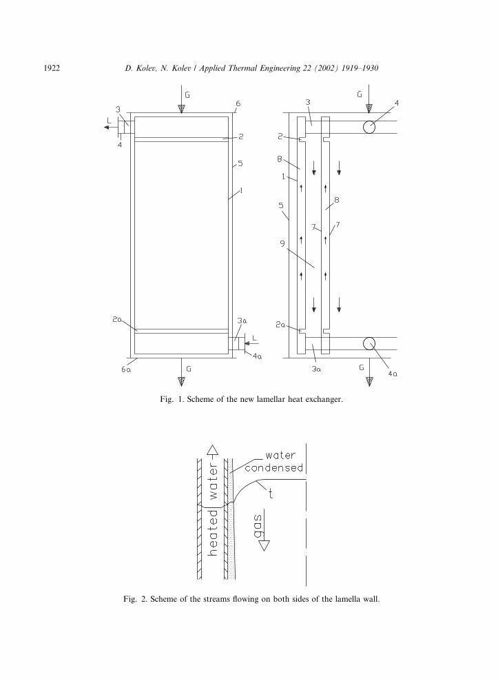
Fig. 1. Scheme of the new lamellar heat exchanger.
Fig. 2. Scheme of the streams flowing on both sides of the lamella wall.
1922 D. Kolev, N. Kolev / Applied Thermal Engineering 22 (2002) 1919–1930
pressed and welded to the other sheets of the same lamellas by means of point welding. The inletand outlet flows of both phases are seen in Fig. 1. A simple scheme of the streams flowing on bothsides of the lamellas wall is represented in Fig. 2. When the heated liquid temperature is lowerthan the dew point of the flue gases, or more precisely, when the temperature of the gas side of thewall is lower than the dew point, additional water condense flow is formed. It flows down over thelamella wall in parallel to the gas flow. On the same figure, the temperature profiles in the threeflows and in the steel wall are schematically shown.
As method for investigating of the new apparatus the mathematical modeling was used.
3. Mathematical model
The simple form of the channels of the new devise and the existing of precise equations forcalculating of the heat transfer coefficient for such channels give the possibility to investigate theprocesses in them using the mathematical modeling. The method for these types of processes isbased on solving the system of mass and heat transfer differential balance equations, together withthe equations for calculation of the heat and mass transfer coefficients, equations for physical–chemical properties of the fluids and the equilibrium of water vapors as a function of the tem-perature. The boundary conditions are the inlet temperature and inlet humidity of the gas phase,and the outlet temperatures of the liquid and of the gas.
For 1 m2 of the apparatus cross section, the balance equations are:
dQ ¼ aGaðtG � tcÞdh; ð1Þ
dQþ dgH2Or ¼ acaðtc � tW1Þdh; ð2Þ
dQþ dgH2Or ¼ ðkst=dÞaðtW1 � tW2Þdh; ð3Þ
dQþ dgH2Or ¼ aLaðtW2 � tLÞdh; ð4Þ
dQ ¼ ðGcPG þ GxcPH2OÞdtG; ð5Þ
dgH2O ¼ kGaðcH2O � c�H2OÞdh; ð6Þ
dQþ dgH2Or ¼ LqLCLdtL � LcqLCLdtLc ; ð7ÞLc and x can be calculated using the expressions:
Lc ¼Z l
0
kGaðcH2O � c�H2OÞ
qL
dh; ð8Þ
x ¼ x0 þZ l
0
kGaðcH2O � c�H2OÞ
Gdh: ð9Þ
In order to eliminate some calculation difficulties connected with the large number intermediatetemperatures that have to be obtained, the following equation is used instead of Eqs. (1)–(4):
D. Kolev, N. Kolev / Applied Thermal Engineering 22 (2002) 1919–1930 1923

dQ ¼ KaðtG � tLÞdh: ð10ÞThe local overall heat transfer coefficient K in Eq. (10) is determined by:
K ¼ 1 : ð1=aG þ Kq=ac þ Kqd=k þKq=aLÞ; ð11Þwhere
Kq ¼ ðdQþ dgH2OrÞ=dQ: ð12ÞThe values of the specific heat of the flue gas components as a function of the temperature and thevalue of ‘‘r’’ are calculated using the equations given in [8]. The equilibrium concentration of thewater vapor in the flue gas was calculated by means of equations, represented in [10].
The equations for calculating the heat transfer coefficients are as follows:For gaseous phase heat transfer coefficient aG:
NuG ¼ 0:021eRe0:8G Pr0:4G ; ð13ÞEq. (13), taken from the literature [7], is valid for ReG greater than 10,000. In order to extend itsvalidity for lower values of ReG, we have multiplied Eq. (10) by a function of ReG, namely fReG.
For 3000 < ReG < 5000
fReG ¼ 0:00292Re0:67G ; ð14ÞFor 5000 < ReG < 10; 000
fReG ¼ 0:225Re0:16G : ð15ÞThe expressions for fReG have been obtained using data from [7]:
The heat transfer coefficient of the condensed film aC is obtained by:
aC ¼ 2:04ðq2Lk
3LrÞ=ðlðtc � tW1ÞlLÞ
0:25: ð16Þ
In this case, the heated liquid flow is always laminar, and its heat transfer coefficient aL isobtained from:
NuL ¼ 0:1eRe0:33L Pr0:43L Gr0:1ðPrL=PrWÞ0:25: ð17ÞThe Eqs. (16) and (17) are also taken from [7].
The mass transfer coefficient kG can be calculated from the analogy between heat and masstransfer processes. The analogy is accurate in this case, because both phases are uniformly dis-tributed over the apparatus cross-section, and the physical properties of each phase in both heatand mass transfer boundary layers are practically the same.
The most of the necessary physical properties of the fluids are taken from [7]. For gas phasecomponents, the values of specific heat Cp are calculated using equations given in [8].
The boundary conditions are:
at h ¼ 0 tG ¼ tG1; tL ¼ tL2; x ¼ x1at h ¼ H tG ¼ tG2:
The system of differential equations was solved numerically, using an iteration procedure.Because the necessary liquid flow rate is not known in advance, the calculations were started
using as initial value of x2 the equilibrium value for the gas phase bulb temperature. The inves-
1924 D. Kolev, N. Kolev / Applied Thermal Engineering 22 (2002) 1919–1930
tigations have shown that in most cases 2 iterations were enough. It was also found that as muchas about 90% of the temperature difference between tG and tL is consumed in the gas phase. Itmeans that the rest of the heat transfer resistance-of the condensed flow, of the lamellas walls, andof the heated water can be neglected with an error of about 10%.
The pressure drop for the gas flow was calculated using the well-known equation:
DP ¼ khðh=dhÞðw2qG=2Þ; ð18Þwhere kh is friction coefficient, which can be calculated from Blausius equation:
kh ¼ 0:316=Re0:25G : ð19ÞBoth equations are taken from [7].
4. Results
The study was carried out at the following conditions:In all cases the width of heated liquid channel was 1 mm (hydraulic diameter 2 mm). This value
is high enough to ensure low pressure drop for the water stream and easy manufacture of the heatexchanger. On the other hand, it is small enough to ensure low pressure drop in the gas phasebecause of higher cross-section for this phase. The thickness of the steel wall of the lamellas wasequal of 0.5 mm. This ensures an easy and cheap preparation of the lamellas and it is possible dueto the fact that the stainless steel is stable to corrosion under these conditions. The value of thehumidity of the air, applied for burning, used in these calculations, was 0.006 kg/kg dry air. Allresults, except for these represented in Fig. 8, are obtained with a coefficient of air excess k, equalto 1.1. The gas humidity at this value of k was x1 ¼ 0:134 kg/kg dry gas.
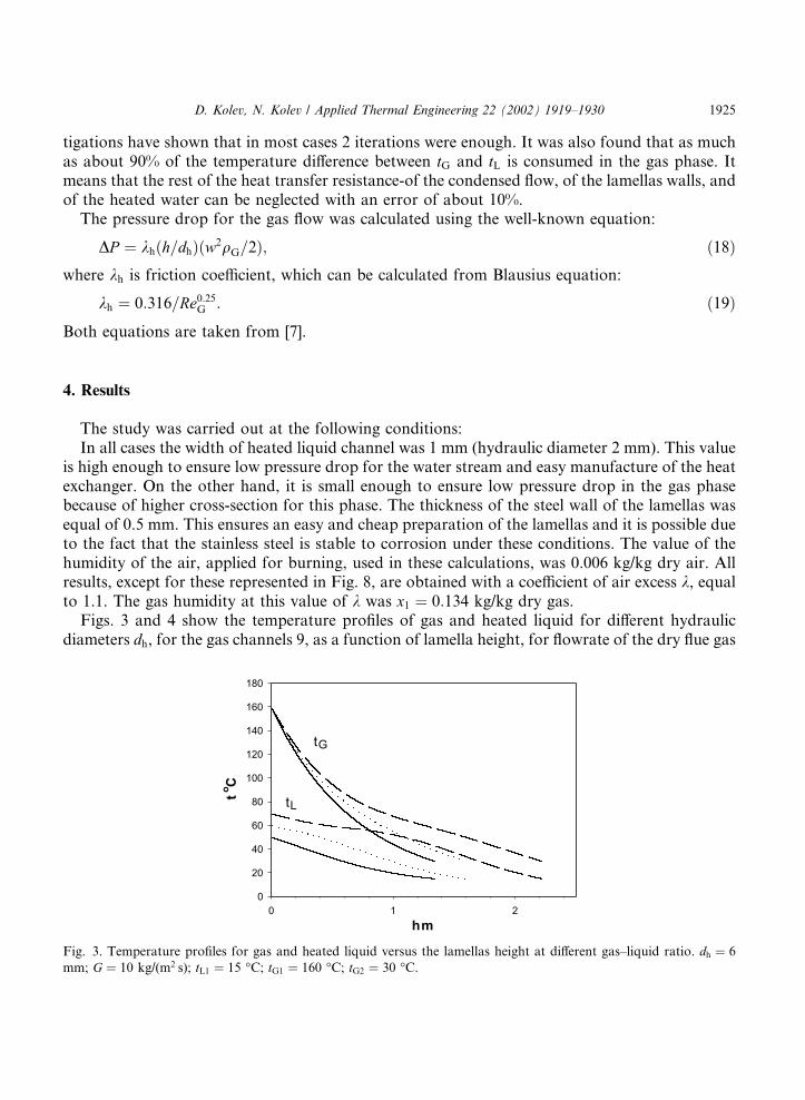
Figs. 3 and 4 show the temperature profiles of gas and heated liquid for different hydraulicdiameters dh, for the gas channels 9, as a function of lamella height, for flowrate of the dry flue gas
Fig. 3. Temperature profiles for gas and heated liquid versus the lamellas height at different gas–liquid ratio. dh ¼ 6
mm; G ¼ 10 kg/(m2 s); tL1 ¼ 15 �C; tG1 ¼ 160 �C; tG2 ¼ 30 �C.
D. Kolev, N. Kolev / Applied Thermal Engineering 22 (2002) 1919–1930 1925
G ¼ 10 kg/(m2s), calculated for the hole cross-section of the apparatus. A comparison of thisfigures with data obtained at the same dimensions of the heat exchanger and initial temperaturesof the gas and liquid phases but with 2 times lower value of G show that practically the tem-perature profiles in this area do not depend from G. It can be explained by the fact that in theinvestigated range of ReG, the heat and mass transfer coefficients calculated by means of Eqs.(13)–(15) is practically proportional to G.
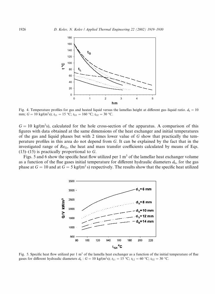
Figs. 5 and 6 show the specific heat flow utilized per 1 m3 of the lamellar heat exchanger volumeas a function of the flue gases initial temperature for different hydraulic diameters dh, for the gasphase at G ¼ 10 and at G ¼ 5 kg/(m2 s) respectively. The results show that the specific heat utilized
Fig. 4. Temperature profiles for gas and heated liquid versus the lamellas height at different gas–liquid ratio. dh ¼ 10
mm; G ¼ 10 kg/(m2s); tL1 ¼ 15 �C; tG1 ¼ 160 �C; tG2 ¼ 30 �C.
Fig. 5. Specific heat flow utilized per 1 m3 of the lamella heat exchanger as a function of the initial temperature of flue
gases for different hydraulic diameters dh : G ¼ 10 kg/(m2s); tL1 ¼ 15 �C; tL2 ¼ 60 �C; tG2 ¼ 30 �C.
1926 D. Kolev, N. Kolev / Applied Thermal Engineering 22 (2002) 1919–1930
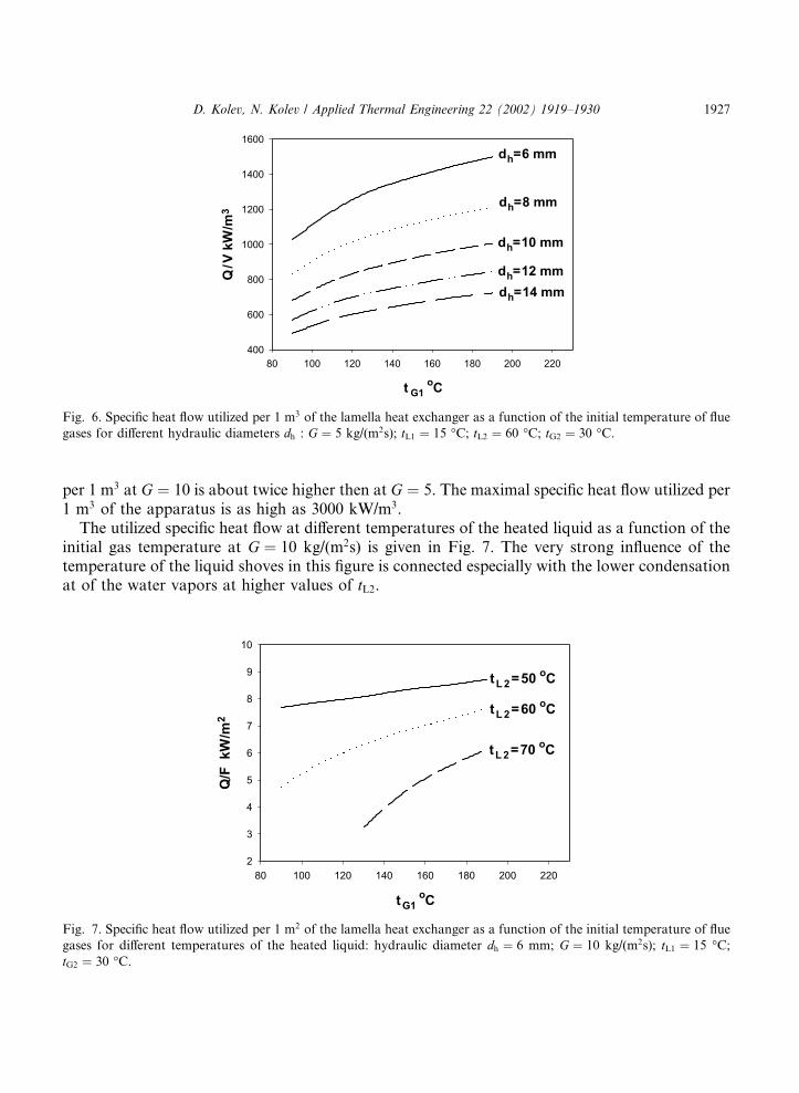
per 1 m3 at G ¼ 10 is about twice higher then at G ¼ 5. The maximal specific heat flow utilized per1 m3 of the apparatus is as high as 3000 kW/m3.
The utilized specific heat flow at different temperatures of the heated liquid as a function of theinitial gas temperature at G ¼ 10 kg/(m2s) is given in Fig. 7. The very strong influence of thetemperature of the liquid shoves in this figure is connected especially with the lower condensationat of the water vapors at higher values of tL2.
Fig. 6. Specific heat flow utilized per 1 m3 of the lamella heat exchanger as a function of the initial temperature of flue
gases for different hydraulic diameters dh : G ¼ 5 kg/(m2s); tL1 ¼ 15 �C; tL2 ¼ 60 �C; tG2 ¼ 30 �C.
Fig. 7. Specific heat flow utilized per 1 m2 of the lamella heat exchanger as a function of the initial temperature of flue
gases for different temperatures of the heated liquid: hydraulic diameter dh ¼ 6 mm; G ¼ 10 kg/(m2s); tL1 ¼ 15 �C;tG2 ¼ 30 �C.
D. Kolev, N. Kolev / Applied Thermal Engineering 22 (2002) 1919–1930 1927
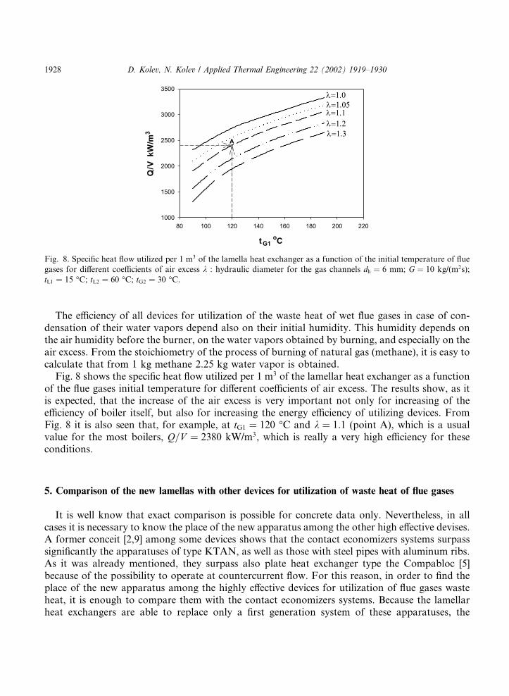
The efficiency of all devices for utilization of the waste heat of wet flue gases in case of con-densation of their water vapors depend also on their initial humidity. This humidity depends onthe air humidity before the burner, on the water vapors obtained by burning, and especially on theair excess. From the stoichiometry of the process of burning of natural gas (methane), it is easy tocalculate that from 1 kg methane 2.25 kg water vapor is obtained.
Fig. 8 shows the specific heat flow utilized per 1 m3 of the lamellar heat exchanger as a functionof the flue gases initial temperature for different coefficients of air excess. The results show, as itis expected, that the increase of the air excess is very important not only for increasing of theefficiency of boiler itself, but also for increasing the energy efficiency of utilizing devices. FromFig. 8 it is also seen that, for example, at tG1 ¼ 120 �C and k ¼ 1:1 (point A), which is a usualvalue for the most boilers, Q=V ¼ 2380 kW/m3, which is really a very high efficiency for theseconditions.
5. Comparison of the new lamellas with other devices for utilization of waste heat of flue gases
It is well know that exact comparison is possible for concrete data only. Nevertheless, in allcases it is necessary to know the place of the new apparatus among the other high effective devises.A former conceit [2,9] among some devices shows that the contact economizers systems surpasssignificantly the apparatuses of type KTAN, as well as those with steel pipes with aluminum ribs.As it was already mentioned, they surpass also plate heat exchanger type the Compabloc [5]because of the possibility to operate at countercurrent flow. For this reason, in order to find theplace of the new apparatus among the highly effective devices for utilization of flue gases wasteheat, it is enough to compare them with the contact economizers systems. Because the lamellarheat exchangers are able to replace only a first generation system of these apparatuses, the
Fig. 8. Specific heat flow utilized per 1 m3 of the lamella heat exchanger as a function of the initial temperature of flue
gases for different coefficients of air excess k : hydraulic diameter for the gas channels dh ¼ 6 mm; G ¼ 10 kg/(m2s);
tL1 ¼ 15 �C; tL2 ¼ 60 �C; tG2 ¼ 30 �C.
1928 D. Kolev, N. Kolev / Applied Thermal Engineering 22 (2002) 1919–1930
comparison will be made with them only. Such a system contains an apparatus for direct heat andmass-transfer (contact economizer) [1], in which the flue gases waste heat is used for warming ofcirculating water. The best apparatuses for this purpose are the packed bed columns with honey-comb packing [1]. The utilized heat is transferred to the heated pure water by indirect heatexchanger. A circulating pump connects both apparatuses. The first advantage of the lamellarheat exchanger is its simpler technological scheme, which together with the very compact con-struction and low weight leads to lower capital investment. For example the weight of the ap-paratus for utilizing of 1 MW heat energy in point A on Fig. 8 is about 600 kg only. Thedisadvantage of this apparatus is that there pressure drop for the gas phase is significant higher.For example the pressure drop in the point A on Fig. 8 is about 3160 Pa. The pressure drop of thecontact economizers is usually only about 100 Pa or 316 times less. The pressure drop for theliquid phase for the lamellar heat exchanger is only about 600 Pa, and the corresponding pressuredrop for the heat exchanger of the contact economizer systems is about 50,000 Pa. Taking intoaccount, that in case of contact economizers there are two water flows––pure water and circu-lating water, and that for the circulating water it has to be added also the pressure drop of theliquid phase distributor and the pressure loss in the tract between the distributor and the waterlevel in the bottom of the contact economizer, which are altogether not less than 22,000 Pa, theenergy loss for the pumps in case of contact economizer systems is about 200 times higher than forthe new lamellar heat exchanger. Nevertheless, the whole energy for pumps and ventilators for thenew lamellar heat exchanger is about 7.9 times higher. The volume of the comparable lamellarheat exchanger is only about 18% of the volume of the contact economizer. Taking into account,that the price of the electrical energy for 1 kWh is about 4 times higher than the price of theutilized heat, and if we accept 60% coefficient of efficiency of the pumps and ventilators, the priceof the consumed electric energy with a lamellar heat exchanger at point A (Fig. 8) will amountonly about 3.4% of the price of the utilized heat energy.
In this case of comparison the final temperature of the heated water is 55 �C for the contacteconomizer system, while it is 60 �C in the case of the lamellar heat exchanger. If the comparisonis made at 55 �C for both apparatuses the pressure drop of the gas phase will be about 2590 Paand the energy consumption with the lamellar heat exchanger will be 6.48 instead of 7.9 foldgreater than in the case of contact economizer. The price of the needed electric energy with thelamellar heat exchanger will be only 2.45% of the price of the utilized heat.
It is well known that the reduction of the gas velocity leads to a decrease in the pressure dropwith this type of apparatuses. The additional calculations show that both types of utilizers willhave practically the same electric energy consumption, at the same temperature of the heatedwater, when the lamellar heat exchanger would have, for example, the following parameters:dh ¼ 12 mm, G ¼ 5 kg/(m2 s), height of the lamellas H ¼ 2:44 m. The utilized heat is 975 kW/m3,i.e. the volume of the lamellar heat exchanger is about 44.53% of the contact economizer volume.The weight of the lamellas is 1006 kg/MW. Taking into account that the lamellar heat exchangerdoes not need any additional pumps and additional plate heat exchanger, it can be easily cal-culated that the capital investment for the lamellar heat exchanger would be significantly lowereven if both types of utilization devices had the same energy consumption.
Another important advantage of the lamellar heat exchanger is that it can heat the water to ahigher temperature than the contact economizers. It�s only, but in some cases essential disad-vantage is that it is not appropriate for operation at higher pressure of the heated liquid.
D. Kolev, N. Kolev / Applied Thermal Engineering 22 (2002) 1919–1930 1929
References
[1] N. Kolev, R. Darakchiev, Kr. Semkov, Systems containing contact economizers for flue gas heat utilization energy
efficiency in process technology, Vouliagmeni (Athens), Greece 10 (1992) 19–22 (Commission of the European
Communities).
[2] D. Kolev, N. Kolev, R. Darakchiev, Technical and economical comparison of contact economizers systems of first
and second generation and heat exchangers with steel pipes with aluminum ribs for utilization of flue gases waste
heat, Proceedings of the scientific conference EMF 2001, Sosopol, Bulgaria.
[3] I.K. Iliev, Y.D. Georgiev, G.L. Atanassov, R.N. Raev, Heat efficiency of condensing economizers of the activated
packing type, Proceedings of VTU ‘‘Angel Kynchev’’, Rousse, vol. XXXV, Heat Technics and Hydraulics Series,
1994, pp. 145–153 (in Bulgarian).
[4] Y. Dochev, I. Iliev, G. Atanassov, Condensing economizer plants for low-grade heat recovery National energy
conference Towards a sustainable energy efficiency in Romania, 1944.
[5] www.us.thermal.alfalaval.com.
[6] D. Kolev, Heat exchanger for utilization of the flue gases waste heat, Bulgarian Patent Office Application 105903/
14.09.2001.
[7] K.F. Pavlov, P.G. Romankov, A.A. Noskov, Examples and working problems in chemical engineering processes
and apparatuses, Chemistry, Leningrad (1981) (in Russian).
[8] R.C. Reid, J.M. Prausniz, T.K. Sherwood, The Properties of Gases and Liquids, third ed., McGraw-Hill Book
Company.
[9] N. Kolev, Kr. Semkov, R. Darakchiev, A. Mirchev, Utilization systems with contact economizers or apparatus
type KTAN, Toploenergetica 3 (8–9) (1990) 6–10 (in Bulgarian).
[10] Landolt-B€oornstein, Zahlenwerte und Funktionen, Bd. II, Teil 2, Springer-Verlag, Berlin-G€oottingen-Heidelberg,
1962, S 31.
1930 D. Kolev, N. Kolev / Applied Thermal Engineering 22 (2002) 1919–1930