Embed Size (px)
Citation preview
Photoresistors: How to use them to control light
intensity
ECE 480
Team 13: Tunable Light Source
Applications Note

Isaac Davila
Table Of contents:
Introduction Photoresistor Background
Definition Basic Structure Types Wavelength Dependence
Controlling Light Intensity References
Introduction: There are currently over 7 billion people on our planet and this number keeps increasing exponentially.
As the population on Earth keeps increasing there is going to be a greater demand for energy sources.
Right now our main sources of energy come from fossil fuels which are “dirty sources”. These kinds of
sources are relatively cheap and readily available but the penalty is that they create pollution. The safer
alternative to these is renewable energy, which consist of water, geothermal, wind, biomass, and solar
energy. For the most part these types of energy sources are not as pollutant. For that reason it makes
more sense to depend on renewable sources then the alternatives. With this in mind the need for
technology that uses renewable energy is going to increase as well. Solar cells are one of the main
technologies we are currently using which use renewable energy. Solar cells use solar energy and
covert it to electricity. Solar cell production has been rapidly increasing. So our ECE 480 project our
group is responsible for creating a product that could be used to test solar cells. To test the solar cells
our sponsor wants us to design a Tunable Light Source that mimics the spectral contents of the sun. In
theory our device would output light that could be tuned over the spectral range of 400nm to 1100nm
then be placed over a solar cell. Another aspect we could control is the intensity of the light coming
out. In order to manually adjust the intensity we will be using Pulse Width Modulation but this method
may not keep it constant at the value we set. So our team will be using a photoresistor to automatically
adjust the intensity in case it changes from the set value.
Photoresistor Background:
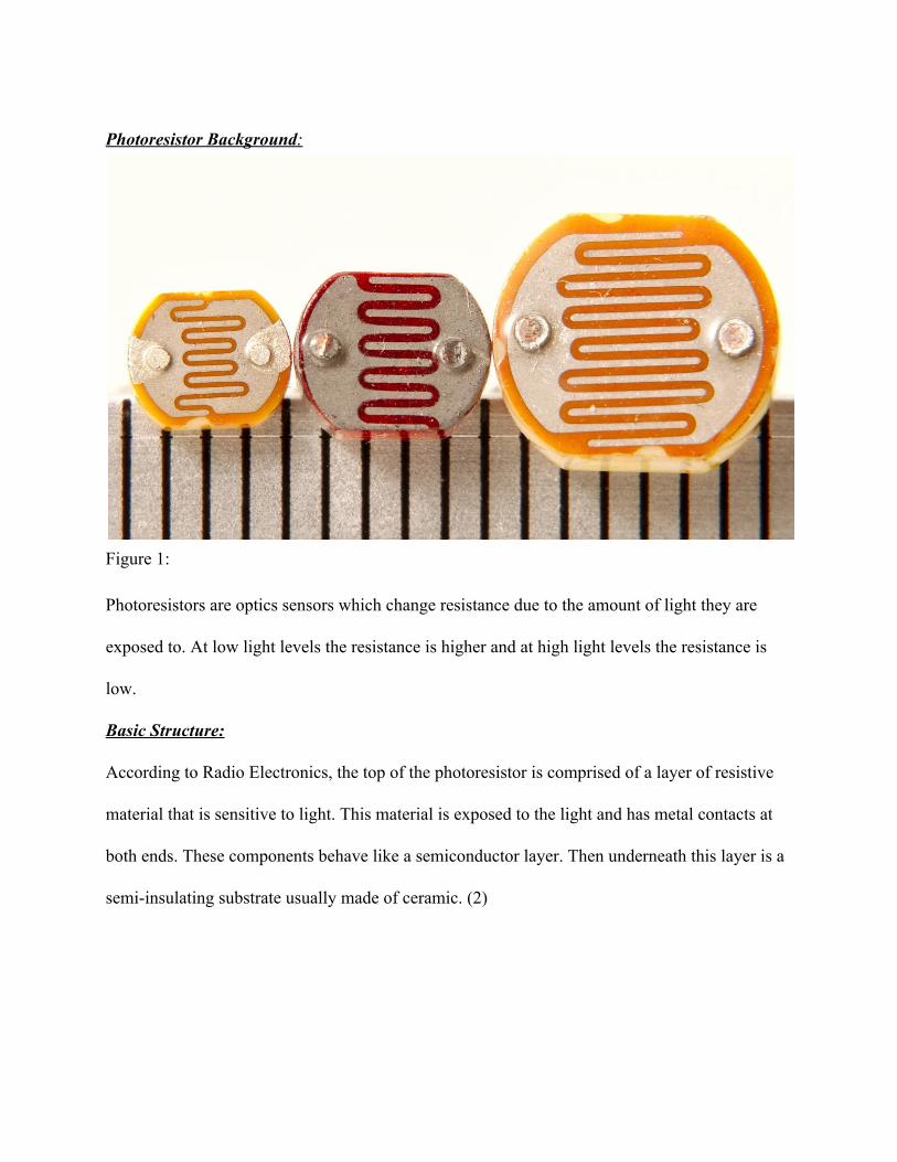
Figure 1: Photoresistors are optics sensors which change resistance due to the amount of light they are
exposed to. At low light levels the resistance is higher and at high light levels the resistance is
low.
Basic Structure:
According to Radio Electronics, the top of the photoresistor is comprised of a layer of resistive
material that is sensitive to light. This material is exposed to the light and has metal contacts at
both ends. These components behave like a semiconductor layer. Then underneath this layer is a
semiinsulating substrate usually made of ceramic. (2)
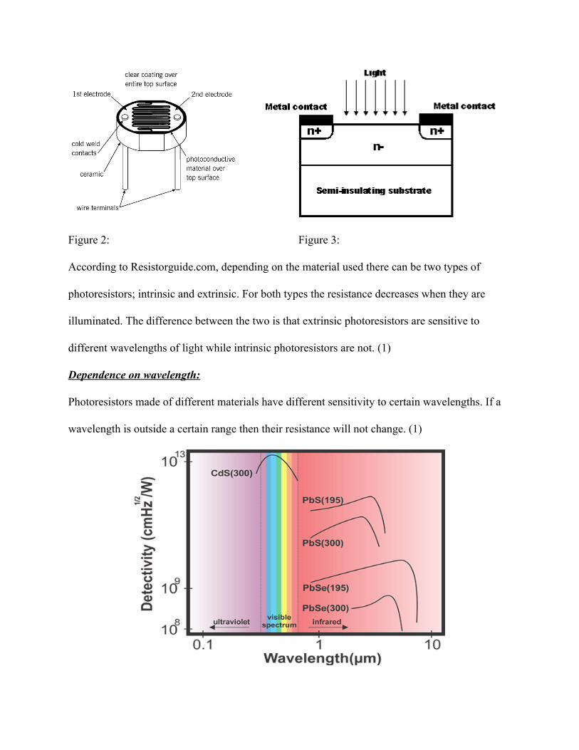
Figure 2: Figure 3:
According to Resistorguide.com, depending on the material used there can be two types of
photoresistors; intrinsic and extrinsic. For both types the resistance decreases when they are
illuminated. The difference between the two is that extrinsic photoresistors are sensitive to
different wavelengths of light while intrinsic photoresistors are not. (1)
Dependence on wavelength:
Photoresistors made of different materials have different sensitivity to certain wavelengths. If a
wavelength is outside a certain range then their resistance will not change. (1)
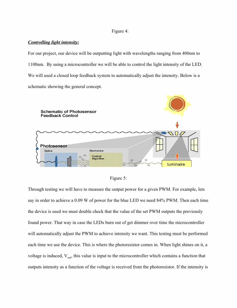
Figure 4:
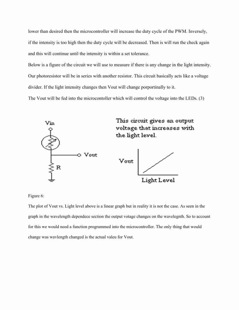
Controlling light intensity:
For our project, our device will be outputting light with wavelengths ranging from 400nm to
1100nm. By using a microcontroller we will be able to control the light intensity of the LED.
We will used a closed loop feedback system to automatically adjust the intensity. Below is a
schematic showing the general concept.
Figure 5:
Through testing we will have to measure the output power for a given PWM. For example, lets
say in order to achieve a 0.09 W of power for the blue LED we need 84% PWM. Then each time
the device is used we must double check that the value of the set PWM outputs the previously
found power. That way in case the LEDs burn out of get dimmer over time the microcontroller
will automatically adjust the PWM to achieve intensity we want. This testing must be performed
each time we use the device. This is where the photoresistor comes in. When light shines on it, a
voltage is induced, Vout, this value is input to the microcontroller which contains a function that
outputs intensity as a function of the voltage is received from the photoresistor. If the intensity is
lower than desired then the microcontroller will increase the duty cycle of the PWM. Inversely,
if the intensity is too high then the duty cycle will be decreased. Then is will run the check again
and this will continue until the intensity is within a set tolerance.
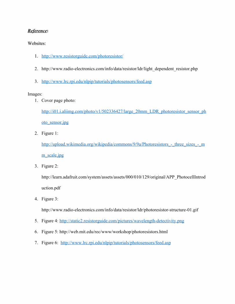
Below is a figure of the circuit we will use to measure if there is any change in the light intensity.
Our photoresistor will be in series with another resistor. This circuit basically acts like a voltage
divider. If the light intensity changes then Vout will change porportinally to it.
The Vout will be fed into the microcontoller which will control the voltage into the LEDs. (3)
Figure 6:
The plot of Vout vs. Light level above is a linear graph but in reality it is not the case. As seen in the
graph in the wavelength dependece section the output votage changes on the wavelegnth. So to account
for this we would need a function programmed into the microcontroller. The only thing that would
change was wavlength changed is the actual valeu for Vout.
Reference: Websites:
1. http://www.resistorguide.com/photoresistor/
2. http://www.radioelectronics.com/info/data/resistor/ldr/light_dependent_resistor.php
3. http://www.lrc.rpi.edu/nlpip/tutorials/photosensors/feed.asp Images:
1. Cover page photo:
http://i01.i.aliimg.com/photo/v1/502336427/large_20mm_LDR_photoresistor_sensor_ph
oto_sensor.jpg
2. Figure 1:
http://upload.wikimedia.org/wikipedia/commons/9/9a/Photoresistors__three_sizes__m
m_scale.jpg
3. Figure 2:
http://learn.adafruit.com/system/assets/assets/000/010/129/original/APP_PhotocellIntrod
uction.pdf
4. Figure 3:
http://www.radioelectronics.com/info/data/resistor/ldr/photoresistorstructure01.gif
5. Figure 4: http://static2.resistorguide.com/pictures/wavelengthdetectivity.png
6. Figure 5: http://web.mit.edu/rec/www/workshop/photoresistors.html
7. Figure 6: http://www.lrc.rpi.edu/nlpip/tutorials/photosensors/feed.asp