Embed Size (px)
Citation preview
Transfer line including vacuum differential systemfor a high-power windowless target
Yuanshuai Qin , Peng Zhang, Hanjie Cai, Yaling Zhang, Huan Jia,* Chenzhang Yuan, Yuan He,Junhui Zhang, and Wenlong Zhan
Institute of Modern Physics, Chinese Academy of Sciences, Lanzhou 730000, People’s Republic of China
(Received 8 March 2020; accepted 8 September 2020; published 17 November 2020)
As the highest power proton linear accelerator in continuous wave mode, China initiative AcceleratorDriven sub-critical System linear accelerator will deliver 2.5 MW proton beam to the target inside thereactor. Vacuum transition from 5 × 10⁴ Pa to several 10−6 Pa is required at the accelerator to targetsection. A vacuum differential system located at the transfer line is designed to meet the requirement of thewindowless target and upstream collimators are considered for power loss control in this paper. A vacuumtest based on vacuum transition verifies that about 10 orders of magnitude vacuum transition could beachieved as required, and gas scattering simulation shows that the power loss and beam size increase are atan acceptable level before the last magnet.
DOI: 10.1103/PhysRevAccelBeams.23.113002
I. INTRODUCTION
China initiative Accelerator Driven subcritical System(CiADS) project was approved by the Chinese government,aiming to demonstrate the nuclear waste transmutation,including a superconducting (SC) linear accelerator (linac),a high-power target, and a reactor. The accelerated protonbeam will hit the target to produce high-flux neutrons toboost the transmutation of nuclear waste in the reactor [1].The SC linac of CiADS will be operated at 2 K
temperature and the beam power will reach 2.5 MW withthe energy of 500 MeV and the current of 5 mA incontinuous wave (CW) mode (as shown in Table I) [2],with the potential for upgrading to 1 GeV or even higherenergy in the future, as shown in Fig. 1. The mainaccelerator structure is SC cavities, and the vacuum shouldbe at the level of several 10−6 Pa. The accelerator to target(A2T) section is designed to deliver the high-power beamto the target and meet the requirement of vacuum transitionmeanwhile. The beam is bent horizontally 90° and thenvertically 90° to match the target inside the reactor, withlocal achromatic design.In the long horizontal transport section, there are colli-
mation section and vacuum differential system (VDS)
section. The dispersion function is zero in the collimationsection, as shown in Figs. 2 and 3.For the high-power target, the vacuum environment at
the target section is far higher than that in the SC sectionand the vacuum should be separated between them, i.e.,vacuum transition. According to the requirement of CiADStarget [dense granular target (DGT)[3] or liquid leadbismuth eutectic (LBE)], it is filled with helium gas in5 × 104 Pa pressure. Thus, about 10 orders magnitude forvacuum transition needs to be achieved in the A2T section.Target with beam window is an effective way to realize
vacuum transition, as that has been designed and operatedat SNS [4,5], J-PARC [6,7], CSNS [8–10], and PSI [11,12].The main challenge for beam windows is the high-powerheat deposition and related cooling and shielding. Anotherproblem is the lifetime of the window and related main-tenance and replacement after long term exposure in theproton and neutron radiation environment, especially forhigh-power accelerator and target. According to the expe-rience of MEGAPIE, with additional electromagneticpumps (EMPs) providing bypass jet flow for the beamwindow cooling [13], the highest temperature achieved onthe beam window is 350 °C with 1 MW power beam [14].Based on the irradiation experiment of T91 material, the
TABLE I. Beam parameters in the linac of CiADS.
Parameters Value Unit
Particle Proton …Energy 500 MeVAverage current 5 mADuty factor 100 %Power 2.5 MW
*Corresponding [email protected]
Published by the American Physical Society under the terms ofthe Creative Commons Attribution 4.0 International license.Further distribution of this work must maintain attribution tothe author(s) and the published article’s title, journal citation,and DOI.
PHYSICAL REVIEW ACCELERATORS AND BEAMS 23, 113002 (2020)
2469-9888=20=23(11)=113002(10) 113002-1 Published by the American Physical Society

lifetime of the beam window is limited to be less than 6.8DPA (displacement-per-atom)[15]. For beam current den-sity of 35 μA=cm2, the lifetime of the beam window isabout 3 months with proton energy of 590MeV [16], whichis similar to the proton energy in CiADS. The averageproton beam current (5 mA) at CiADS is 2.8 times of that inMEGAPIE (1.8 mA), but if the beam current density is alsolimited within 35 μA=cm2 for CiADS, the lifetime of thebeam window will be the same as 3 months level.
To avoid the problems accompanied by the beam window,a vacuumdifferential system in A2T is proposed for window-less target design of CiADS. Themain challenge ofVDS is toavoid beam loss on the small vacuumdifferential holes, thus acollimation system upstream is considered.In this paper, first, since the vacuum transition is
achieved by multistage small holes, beam dynamics arestudied and optimized in the code TRACEWIN [17], includ-ing the VDS section and upstream collimation section.Second, for the beam in 5 × 10⁴ Pa at the target zone and100 Pa at the transition zone (as shown in Fig. 2), the gasscattering effect between the proton beam and the heliumgas is simulated to check beam size increase and powerlosses in the beam tube. Third, a vacuum differential testbench is built to verify the feasibility of VDS.
II. BEAM DYNAMICS
Since the vacuum pressure varies from 10−6 Pa to104 Pa, all the three types of flow are presented in theVDS. For a tube or hole, the effect of vacuum transitiondepends on the pressure difference [18]:
Δp ¼ QC; ð1Þ
where C ¼ 16
ffiffiffiffiffiffiffiffi2πRTM
q· d
3
L and C ¼ffiffiffiffiffiffiffiffiffiffiffi2γγ−1
RTM
q· x
1γ
ffiffiffiffiffiffiffiffiffiffiffiffiffiffiffi1 − x
γ−1γ
q·
11−x
π4· d2 are the conductance for molecular flow in a long
tube and viscous flow in a thin hole respectively [19],where d is the diameter and L is the length of the tube.Knudsen flow is between molecular flow and viscous flowand the conductance for molecular flow is adopted to makea conservative estimation of Knudsen flow in the design,
i.e., C ¼ffiffiffiffiffiffiffiRT2πM
q· π4· d2. It indicates that reducing the diam-
eter or increasing the length of the tube are beneficial forthe vacuum transition, where reducing the diameter is moreeffective for molecular flow in a long tube. In beamdynamics, a beam waist with a small root mean square(RMS) beam size in both horizontal and vertical planes isneeded to avoid beam losses at the vacuum differen-tial holes.
A. Beam from linac
The beam coming out from the linac can be consideredas a Gaussian beam. For two-dimensional Gaussian dis-tribution ðX; YÞ ∼ Nðμx; μy; σ2x; σ2y; rÞ, the distribution func-tion is
fðμx; μy; σ2x; σ2y; rÞ ¼1
σxσy · 2πffiffiffiffiffiffiffiffiffiffiffiffi1 − r2
p
· e− 1
2ð1−r2Þ½ðx−μxÞ2
σ2x−2rðx−μxÞðy−μyÞ
σxσyþðy−μyÞ2
σ2y�; ð2Þ
FIG. 1. The layout of the CiADS accelerator.
FIG. 2. CiADS A2T layout including VDS.
FIG. 3. 5σ envelope and dispersion function at CiADS A2Tsection. (The maximum dispersion function is about Dx ¼ 3.3 mand Dy ¼ 4.4 m).
YUANSHUAI QIN et al. PHYS. REV. ACCEL. BEAMS 23, 113002 (2020)
113002-2
where μx, μy is the beam center, σx, σy is the beam RMSsize, and r is the correlation coefficient between x and y. Indesign consideration, the beam shape at the collimators iscentered, round, and uncoupled, i.e., μx ¼ μy ¼ 0,σx ¼ σy ¼ σ, r ¼ 0, then the function is written as fð0; 0;σ2; σ2; 0Þ ¼ 1
2πσ2· e−
x2þy2
2σ2 , and the probability density insideN · σ takes:
P ¼Z
Nσ
−Nσ
Z ffiffiffiffiffiffiffiffiffiffiffiffiffiffiðNσÞ2−x2
p
−ffiffiffiffiffiffiffiffiffiffiffiffiffiffiðNσÞ2−x2
p 1
2πσ2e−
x2þy2
2σ2 dxdy; ð3Þ
and the probability density outside N · σ is 1 − P.
B. Hole aperture selection
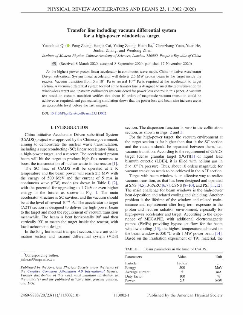
Equation (3) cannot be solved analytically, and thenumerical solution is shown in Table II. According tothe experience of SNS, power loss on collimators should becontrolled within the level of several kW [20]. Thus, 4σ isthe minimum value that needs to be set at collimatorsaccording to Table II. Considering margins and errors, thecollimator hole radius is set as 5σ in the collimation sectionfor CiADS.
C. Beam optics in vacuum differential system
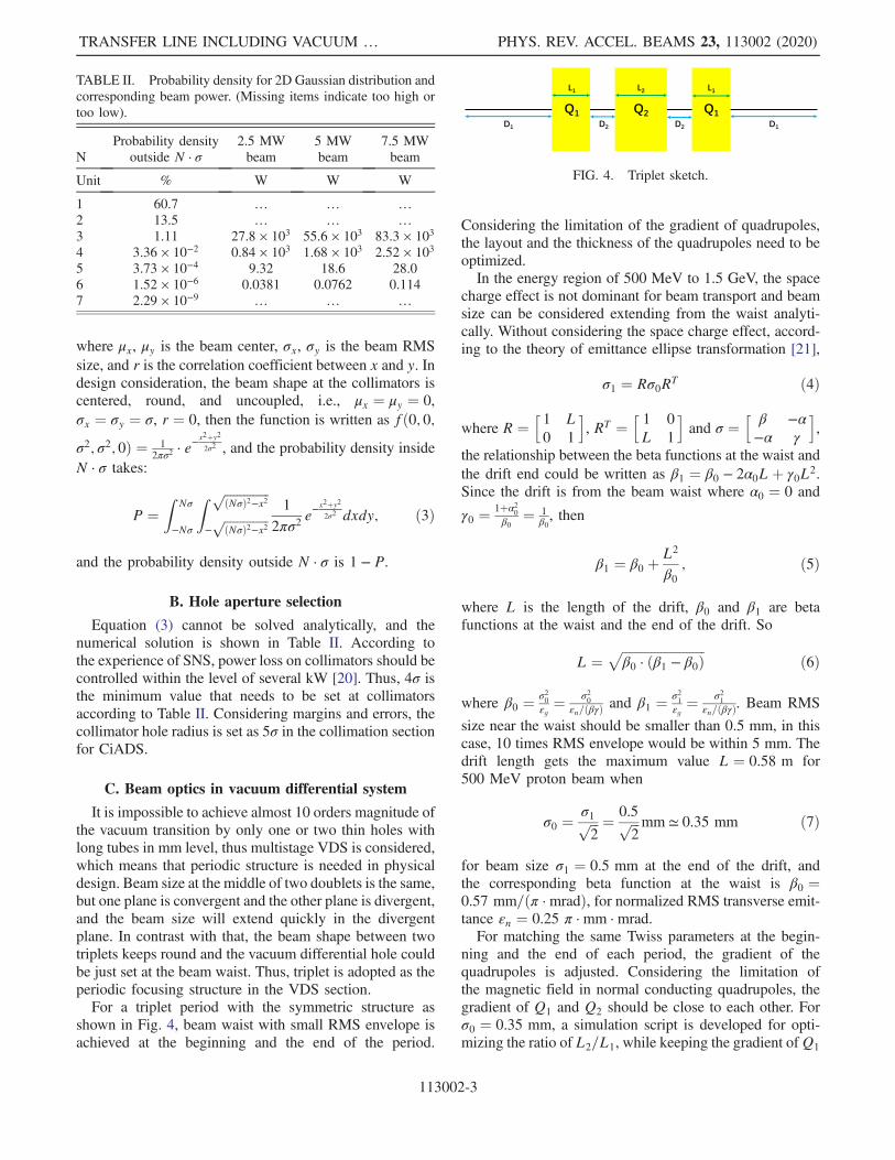
It is impossible to achieve almost 10 orders magnitude ofthe vacuum transition by only one or two thin holes withlong tubes in mm level, thus multistage VDS is considered,which means that periodic structure is needed in physicaldesign. Beam size at the middle of two doublets is the same,but one plane is convergent and the other plane is divergent,and the beam size will extend quickly in the divergentplane. In contrast with that, the beam shape between twotriplets keeps round and the vacuum differential hole couldbe just set at the beam waist. Thus, triplet is adopted as theperiodic focusing structure in the VDS section.For a triplet period with the symmetric structure as
shown in Fig. 4, beam waist with small RMS envelope isachieved at the beginning and the end of the period.
Considering the limitation of the gradient of quadrupoles,the layout and the thickness of the quadrupoles need to beoptimized.In the energy region of 500 MeV to 1.5 GeV, the space
charge effect is not dominant for beam transport and beamsize can be considered extending from the waist analyti-cally. Without considering the space charge effect, accord-ing to the theory of emittance ellipse transformation [21],
σ1 ¼ Rσ0RT ð4Þ
where R ¼h1 L0 1
i, RT ¼
h1 0
L 1
iand σ ¼
h β −α−α γ
i,
the relationship between the beta functions at the waist andthe drift end could be written as β1 ¼ β0 − 2α0Lþ γ0L2.Since the drift is from the beam waist where α0 ¼ 0 and
γ0 ¼ 1þα20
β0¼ 1
β0, then
β1 ¼ β0 þL2
β0; ð5Þ
where L is the length of the drift, β0 and β1 are betafunctions at the waist and the end of the drift. So
L ¼ffiffiffiffiffiffiffiffiffiffiffiffiffiffiffiffiffiffiffiffiffiffiffiffiffiffiβ0 · ðβ1 − β0Þ
pð6Þ
where β0 ¼ σ20
εg¼ σ2
0
εn=ðβγÞ and β1 ¼ σ21
εg¼ σ2
1
εn=ðβγÞ. Beam RMS
size near the waist should be smaller than 0.5 mm, in thiscase, 10 times RMS envelope would be within 5 mm. Thedrift length gets the maximum value L ¼ 0.58 m for500 MeV proton beam when
σ0 ¼σ1ffiffiffi2
p ¼ 0.5ffiffiffi2
p mm ≃ 0.35 mm ð7Þ
for beam size σ1 ¼ 0.5 mm at the end of the drift, andthe corresponding beta function at the waist is β0 ¼0.57 mm=ðπ · mradÞ, for normalized RMS transverse emit-tance εn ¼ 0.25 π · mm · mrad.For matching the same Twiss parameters at the begin-
ning and the end of each period, the gradient of thequadrupoles is adjusted. Considering the limitation ofthe magnetic field in normal conducting quadrupoles, thegradient of Q1 and Q2 should be close to each other. Forσ0 ¼ 0.35 mm, a simulation script is developed for opti-mizing the ratio of L2=L1, while keeping the gradient ofQ1
FIG. 4. Triplet sketch.
TABLE II. Probability density for 2D Gaussian distribution andcorresponding beam power. (Missing items indicate too high ortoo low).
NProbability density
outside N · σ2.5 MWbeam
5 MWbeam
7.5 MWbeam
Unit % W W W
1 60.7 … … …2 13.5 … … …3 1.11 27.8 × 10³ 55.6 × 10³ 83.3 × 10³
4 3.36 × 10⁻² 0.84 × 10³ 1.68 × 10³ 2.52 × 10³
5 3.73 × 10⁻⁴ 9.32 18.6 28.06 1.52 × 10⁻⁶ 0.0381 0.0762 0.1147 2.29 × 10⁻⁹ … … …
TRANSFER LINE INCLUDING VACUUM … PHYS. REV. ACCEL. BEAMS 23, 113002 (2020)
113002-3

and Q2 almost the same. For a fixed drift length D2
between the quadrupoles in the triplet, there is a minimumlength for D1 before the triplet in a period for keepingthe stable periodic envelope. Considering backward
compatibility for energy, the ratio L2=L1 should be around1.4 mainly based on 1.5 GeV beam, and it is also coveredby lower energy cases, as shown in Fig. 5.To optimize D2 and D1, the gradient of quadrupoles is
limited within 25� 0.5 T=mwith the radius of 30 mm, andthe comparison results are shown in Fig. 6. Normally,thinner quadrupoles, smaller maximum RMS size, andshorter period length are preferred, so D2 ¼ 150 mm ischosen as the optimized value where there is a localminimum for beam maximum RMS size, and relatedparameters are listed in Table III. In that case, the polarfield is within 8000 Gs for the highest energy, and thediameter of the VDS holes is chosen as 10 mm. Beamenvelope and power density level are shown in Figs. 7 and 8with different energies.
D. Collimation
Since the VDS holes are small, beam halo or off-centerbeam will lead to a large amount of power loss. To controlbeam losses at certain key locations, the separated function
-2 0 21.2
1.4
1.6
D2=50 mm
D1=1080 mm
-2 0 21.2
1.4
1.6
L2/L
1
-2 0 21.2
1.4
1.6
-2 0 21.2
1.4
1.6
D2=75 mm
D1=1090 mm
-2 0 21.2
1.4
1.6
-2 0 21.2
1.4
1.6
-2 0 21.2
1.4
1.6
D2=100 mm
D1=1100 mm
-2 0 21.2
1.4
1.6
-2 0 2|G
1|-|G
2| (T/m)
1.2
1.4
1.6
-2 0 21.2
1.4
1.6
D2=125 mm
D1=1110 mm
-2 0 21.2
1.4
1.6
-2 0 21.2
1.4
1.6
-2 0 21.2
1.4
1.6
E=
500
MeV
D2=150 mm
D1=1120 mm
-2 0 21.2
1.4
1.6
E=
1 G
eV
-2 0 21.2
1.4
1.6
E=
1.5
GeV
FIG. 5. The ratio of thickness and gradient difference. (G1
and G2 indicate the gradient of Q1 and Q2, L1 and L2 are thethickness of Q1 and Q2, D2 is the drift length between quadru-poles in the triplet, D1 is the drift length before the firstquadrupole in the triplet. In some cases, the distribution isseparated into two branches and the lower L2=L1 ones are forthicker quadrupoles, which is not preferred.)
50 100 150 200 250 300D
2 (mm)
300
500
700
900
1100
1300
1500
Leng
th (
mm
)
D1
L1
L2
50 100 150 200 250 300D
2 (mm)
24.5
24.7
24.9
25.1
25.3
25.5
Gra
dien
t (T
/m)
G1
-G2
50 100 150 200 250 300D
2 (mm)
90
120
150
180
Per
iod
phas
e ad
vanc
e (°
)
x-0.5 GeV
x-1.0 GeV
x-1.5 GeV
y-0.5 GeV
y-1.0 GeV
y-1.5 GeV
50 100 150 200 250 300D
2 (mm)
2
2.1
2.2
2.3
2.4
2.5
Max
imum
RM
S s
ize
(mm
)
4
4.2
4.4
4.6
4.8
5
Per
iod
leng
th (
m)
Maximum y-0.5
GeV
Period Length
FIG. 6. Optimization on D2 and D1. (With D2 increases, D1 isincreasing, while L1 and L2 are decreasing; the gradient is limitedwithin 25� 0.5 T=m; periodic phase advance increases in Yplane and decreases from about 180° in X plane; beam maximumRMS size and period length are increasing roughly.)
TABLE III. Parameters for different proton energies in VDS fornD1 ¼ 1130 mmD2 ¼ 150 mm
,nL1 ¼ 460 mmL2 ¼ 640 mm
,nG1 ¼ 25.2248 T=mG2 ¼ −25.1764 T=m
.
Parameters Unit Values
Energy MeV 500 1000 1500Magnetic rigidity T · m 3.636 5.657 7.507βγ … 1.162 1.808 2.399Beam RMS size at the waist mm 0.35 0.35 0.35β function at the waist mm=ðπ ·mradÞ 0.569 0.886 1.175X periodic phase advance ° 179.2 176.5 168.6Y periodic phase advance ° 142.2 124.0 109.8Highest polar field strength Gs 3927 5995 7567Maximum RMS envelope mm 2.10 1.44 1.15
12 14 16 18 20 22 24 26 28 30 320
1
2
3
4
5
x func
tion
(m) x
-500 MeV
x-1.0 GeV
x-1.5 GeV
12 14 16 18 20 22 24 26 28 30 32Z (m)
0
5
10
15
20
25
y func
tion
(m) y
-500 MeV
y-1.0 GeV
y-1.5 GeV
FIG. 7. β function in VDS. (Beam sizes are the same at vacuumholes for different energies. Since the geometric emittance forlower energy beam is larger, β function at the waist is smaller).
FIG. 8. Power density level in VDS. (Y-axis indicates radiusin mm, from top to bottom: beam energy E ¼ 500, 1000,1500 MeV).
YUANSHUAI QIN et al. PHYS. REV. ACCEL. BEAMS 23, 113002 (2020)
113002-4

of collimation and VDS are considered. Thus, no watercooling is considered in VDS holes, and the beam iscollimated upstream of the VDS section.The main function of the collimation section is to
collimate the outer particles in the phase space to avoidthem losing at the VDS holes, which means that theemittance of the beam at the exit of the collimation section
should be well inside the acceptance of the VDS section.For full collimation, the total phase advance (or rotation inphase space) should be at least 180° in the collimationsection. Figure 9 shows the acceptance of VDS for differentenergies. Since periodic phase advance in X plane for500 MeV and 1 GeV are quite near to 180°, they look likedeviated from the “elliptical” acceptance.As shown in Fig. 9, the acceptance at 1.5 GeV is smaller
than that at 500 MeV or 1 GeV, which is the object in thestudy below. For the same reason as mentioned inthe VDS section, the triplet is chosen as the periodicstructure in the collimation section. Different periodicphase advances are compared and optimized as shown inTable IV and 60° phase advance multiply 3 periods isadopted. The reason is as follows: 1. Comparing to 90°collimation, 60° collimation has much less particles outsideof the desired emittance, as it has been discussed at CERN[22]; 2. With the increase of periodic phase advance, thenumber of periods and quadrupoles are decreasing. Thus,higher phase advance with shorter length and fewerquadrupoles is preferred from the cost view, as long asit meets the collimation requirements; 3. Larger radius ofcollimators is preferred based on the consideration of beamcenter offset, errors and the heat distribution on collimators;4. The maximum beam size is acceptable both in theperiodic section and matching section, while the polar fieldstrength increases sharply with the increase of periodic
FIG. 9. Acceptance of VDS for different energies. To avoid toolarge position or angle in phase space, the acceptance calculationincludes part of the matching section between the collimation andthe VDS, i.e., from the end of the last quadrupole Q5 of thematching section until the end of VDS. (From left to right: beamenergy E ¼ 500, 1000, 1500 MeV; the top is for X-X’ and thebottom is for Y-Y’)
TABLE IV. Comparison of different periodic phase advance in the collimation section for 1.5 GeV beam.
Periodic phase advance 30° 36° 45° 60° 90°
Number of periods 6 5 4 3 2Total length [m] 15 12.5 10 7.5 5Number of quadrupoles 18 15 12 9 6Collimators radiusin X/Y planes [mm]
3.73=3.37 3.40=3.01 3.08=2.64 2.73=2.20 2.33=1.63
σmax in periodic/matching section [mm]
0.82=1.07 0.77=1.00 0.72=0.99 0.69=1.01 0.70=1.11
Gmax · R in periodic/matchingsection [Gs]
3701=5783 4417=5917 5464=6167 7126=6598 10041=7191
5σ envelope
Emittance edge X-X0
Emittance edge Y-Y0
TRANSFER LINE INCLUDING VACUUM … PHYS. REV. ACCEL. BEAMS 23, 113002 (2020)
113002-5

phase advance, and it is within 8000 Gs for the case of 60°phase advance.From the view of emittance after the collimation section,
xmax and x0max are within 1.8 mm and 1.6 mrad for thecases with periodic phase advance of 60°. Balancing allthe considerations mentioned above, 60° × 3 periods isadopted as the optimum choice in the collimation section.To check the effectiveness of the collimation section, the
emittance after the collimation section and the acceptanceof the VDS section are put together, as shown in Fig. 10 for1.5 GeV beam. The acceptance of VDS is about 7 times ofthe emittance edge of the collimation section.
E. Multiparticle tracking
The input distribution of the collimation section ischosen as 2D Gaussian distribution cutting at 6 standarddeviations as shown in Fig. 11. The input normalizedRMS emittance is εx=y=z ¼ 0.25=0.25=0.35 π · mm · mrad.To check the case with beam halo, 0.1% halo is added in theinput distribution. The diameter of the 3 collimators isadjusted to 5.6σ=5.0σ=4.4σ to guarantee that the power losson the collimators is evenly distributed.Based on the optimized VDS and collimation section
at 1.5 GeV energy, the 5σ envelope and power density
distribution are shown in Fig. 12 and Fig. 13. Power losseson each collimator are about 10 Wand 1.3 kW for the beamwith and without the halo, and there is no power loss in theVDS section in all cases (Fig. 14).Detailed sensitivity analysis on the input beam trajecto-
ries, manufacturing errors and alignment errors of colli-mators are studied. The criterion is based on the power losson collimators. Since it is already at kW level, we assumethat the power loss variation caused by errors should bewithin 10% of the designed maximum power loss oncollimators. For trajectory errors, when the input beamcenter is shifted by 0.1 mm, or the input beam angle isshifted by 0.025 mrad, the power loss variation is about2.5%. The same method is applied for the manufacturingerrors and alignment errors of the collimators and theresults are 0.05 mm and 0.2 mm respectively. When all theerrors are applied in the lattice, the total power lossvariation is within 10%, which is within the scope ofdemand. In general, the input beam trajectories should bewithin dx=dy ¼ �0.1 mm, dx0=dy0 ¼ �0.025 mrad, andthe manufacturing errors and alignment errors should bewithin �0.05 mm and �0.2 mm, respectively.
F. Feasibility
Beam dynamics are studied and optimized, including thehole aperture in the VDS section and periodic phaseadvance in the collimation section. Multiparticle tracking
FIG. 10. Emittance of the collimation section and acceptance ofthe VDS section for 1.5 GeV beam. The dark area is theacceptance of VDS section. The white hexagonal area is themaximum beam emittance after collimation. Particles in blue andyellow colors are collimated beam emittance.
FIG. 11. Input distribution of collimation section. (Top forbeam without halo, bottom for beam with 0.1% halo).
FIG. 12. 5σ envelope in optimized collimation and VDS sectionfor 1.5 GeV beam.
FIG. 13. Power density distribution in optimized collimationand VDS section for 1.5 GeV beam with 0.1% halo. (Top for Xplane and bottom for Y plane).
YUANSHUAI QIN et al. PHYS. REV. ACCEL. BEAMS 23, 113002 (2020)
113002-6

with halo shows that no power lost in VDS holes, verifyingthe beam dynamics feasibility of vacuum differentialsystem for the high-power windowless target of CiADS.
III. GAS SCATTER
A. Mechanism and method
As shown in Fig. 2, there is about 30 meters from the lastvacuum hole to the target, which is filled with helium gas in5 × 104 Pa (target zone), and another 30 meters with heliumgas in about 100 Pa (transition zone). The proton heliumscattering will lead to beam size increase and power loss onthe beam tube.As charged hadronic particle, proton will be scattered by
helium nucleus due to Coulomb interactions and hadronicinteractions when transporting in helium gas. Unlikehadronic elastic process, the Coulomb interaction betweenproton and helium usually leads to small-angle scattering.Because the beam tube is quite slender, single hadronicelastic scattering can easily lead to the loss of the particle,while the effect of Coulomb scattering will accumulatealong the long tube, resulting in a considerable overall lossrate. The longer the beam tube is, the more significant theaccumulated effect will be. Thus, both Coulomb scatteringand hadronic process should be taken into considerationcarefully.The gas scattering effect is investigated base on the
Monte Carlo simulation using GEANT4.10.6 [23] in thissection. For Coulomb scattering process, the WVI-SS[24,25] model which naturally combines the Wentzel-VImultiple scattering model [23,24] and the single scatteringmodel based on Wentzel scattering function [26] isused. The Wentzel-VI model is for precise simulation ofmuons and hadrons. The combination of single andmultiple scattering models presents precise description ofCoulomb scattering effect even in low-density media.As for hadronic elastic process, the G4ChipsElasticModel
[23] based on CHIPS approach [27] is adopted. It was shown[23] that the CHIPS model is the most reliable one amongall of the four options exist in GEANT4 for simulationof proton-nucleus elastic scattering at medium and highenergy protons.
B. Simulation
The simulation is based on the beamline near the target,with helium vacuum pressure of 5 × 10⁴ Pa and 100 Pa for5 mA proton beam, as shown in Fig. 2. The beam tube is316 stainless steel with 5 mm thick. Without scattering,beam RMS size is about 5.5 mm for transition zone and19 mm on the target for Gaussian distribution.In the transition zone where the vacuum is about 100 Pa,
the maximum power loss on the tube is within 1.5 W=m(Fig. 15), and it is human maintainable in this zone.As shown in Fig. 16, beam loss is mainly caused by
Coulomb scattering in transition zone, but it still stays atseveral W/m level. In the target zone, beam power loss isdominated by Hadronic elastic process, up to severalhundred W/m, which is far higher than 1 W=m hands-on maintenance level in the accelerator [28]. Thus, theremote control is required in this zone due to the highradiation dose rate.The gas scattering will also lead to beam size increase.
The effect of gas scattering on beam size increase in thetransition zone is neglectable, and it increases 18% in theworst case for the 500 MeV beam in the target zone. Forcircular scan, extra power loss on the tube contributed bybeam size increase is 47 W, 7.5 W, 6.8 W for the threedifferent energies. Since there would be cooling on the tubebefore the target, dozens of watts loss would be acceptable.To decrease the effect, smaller beam size on the target orlarger beam tube near the target are considered. If thedesigned beam RMS size on the target decreases by 1 mm,
Lo
sses
(W
)
0200400600800
1,0001,2001,400
Position (m) Total=4200.04 W0 5 10 15 20 25 30
FIG. 14. Power loss distribution for the beam with 0.1% halo(about 1.3 kW for each collimator). No power loss in the VDSsection.
0 5 10 15 20 25 300
0.5
1
1.5
Hea
t in
wal
l (W
/m) Transition zone
500 MeV1000 MeV1500 MeV
0 5 10 15 20 25 30Position (m)
0
50
100
150
Hea
t in
wal
l (W
/m)
Target zone
500 MeV1000 MeV1500 MeV
FIG. 15. Power loss on the beam tube for different energies intransition and target zone.
0 5 10 15 20 25 30
Z (m)
0
50
100
150
200
250
300
350
400
Bea
m lo
ss (
W/m
)
Target zone
500 MeV-Coulomb Scattering1000 MeV-Coulomb Scattering1500 MeV-Coulomb Scattering
500 MeV-Hadronic Elastic Process1000 MeV-Hadronic Elastic Process1500 MeV-Hadronic Elastic Process
0 5 10 15 20 25 30
Z (m)
00.5
11.5
22.5
33.5
4
Bea
m lo
ss (
W/m
)
Transition zone 500 MeV-Coulomb Scattering1000 MeV-Coulomb Scattering1500 MeV-Coulomb Scattering
500 MeV-Hadronic Elastic Process1000 MeV-Hadronic Elastic Process1500 MeV-Hadronic Elastic Process
FIG. 16. Beam loss caused by gas scattering in transition andtarget zone.
TRANSFER LINE INCLUDING VACUUM … PHYS. REV. ACCEL. BEAMS 23, 113002 (2020)
113002-7

or the radius of beam tube increases by 5 mm, the powerloss will decrease sharply from 47 W to 17 W for the500 MeV beam.
C. Feasibility
In the transition zone with the vacuum level of about100 Pa, beam loss and beam size increase are acceptable. Inthe target zone, the gas scattering effect is serious, and adedicated radiation-hard design and remote control need tobe considered in that region, and beam size should becontrolled smaller or beam tube larger to balance the beamsize increase caused by gas scattering for low energybeam.
IV. VACUUM DIFFERENTIAL TEST
A. System setup
A prototype for the vacuum differential system with 6stages is designed and tested at the Institute of ModernPhysics, Chinese Academy of Sciences, as shown in Fig. 17.Taking the above simulation results, long thin tubes with adiameter of 10 mm is chosen at the 1st, 2nd, and 3rd stages,and small holes with the same diameter is chosen at the reststages ofVDS, as shown inFig. 18.AISI304 stainless steel ischosen as the material of vacuum chambers and the leakagerate is within 1 × 10⁻¹⁰ mbar · L=s. All the chambers andtubes are mirror polished, pickled, ultrasonic cleaned andhigh temperature degassed before the test.Considering the ratio of the diameter of the tube and the
mean free path (MFP) of the molecules of hydrogen orhelium, it is viscous flow in the 1st and 2nd VDS stages,Knudsen flow in the 3rd stage, and molecular flow in the4th, 5th, and 6th stages. Different pumps and gauges arechosen based on the flow type in different stages, as shownin Table V.
B. Test result
In the test, the vacuum transition from 5 × 10⁴ Pa to7.8 × 10−5 Pa was achieved in the multistage VDS forHelium gas for the long-term test, as shown in Fig. 19(Left). When considering vacuum variation in the plenumchamber for the limit test, the vacuum at the 6th stage willbecome much worse when the vacuum pressure in theplenum chamber is beyond 8 × 10⁴ Pa. The same test forNitrogen gas was also conducted and the best vacuum at the
6th stage VDS reached 2.5 × 10⁻⁵ Pa, and it is about halforder lower than the case with Helium gas, which agreeswith the fact that the Nitrogen molecule size is larger thanHelium and it is easier to be pumped out. Figure 20 showsthe comparison results with the different types of gas andinitial pressure in the plenum chamber.For nitrogen, it is easy to realize about 10 orders of mag-
nitude vacuum transition from 1 × 10⁵ Pa to 2.5 × 10⁻⁵ Pa
FIG. 17. The layout of the VDS prototype.
FIG. 18. The sketch of the VDS prototype.
0 5 10 15 20Time (min)
10-5
10-3
10-1
101
103
105
Vac
uum
pre
ssur
e (P
a)
First stageSecond stageThird stageFourth stageFifth stageSixth stage
2 4 6 8 10Inflation pressure (Pa) 104
10-5
10-3
10-1
101
103
105
Vac
uum
pre
ssur
e (P
a)
First stageSecond stageThird stageFourth stageFifth stageSixth stage
FIG. 19. Vacuum test results for Helium gas in VDS. (Left is fora long-term test: vacuum pressure in the plenum chamber stays at5 × 104 Pa; Right is for the limit test: vacuum pressure in theplenum chamber varies from 1 × 10⁴ Pa to 1 × 10⁵ Pa gradually;the six lines from top to bottom: the first to the sixth stage ofVDS).
0 1 2 3 4 5 6Stage of VDS
10-6
10-4
10-2
100
102
104
106
Vac
uum
pre
ssur
e (P
a)
Designed value
N2(P
0=1×10⁵ Pa)
N2(P
0=5×10⁴ Pa)
He(P0=1×10⁵ Pa)
He(P0=5×10⁴ Pa)
FIG. 20. Vacuum comparison with different initial pressure andgas in VDS. (Nitrogen gas: from 1 × 10⁵ Pa to 2.4 × 10⁻⁵ Pa,Helium gas: from 8 × 10⁴ Pa to 7.8 × 10⁻⁵ Pa)
YUANSHUAI QIN et al. PHYS. REV. ACCEL. BEAMS 23, 113002 (2020)
113002-8

in both long-term test and limit test. For helium, it would be3.2 × 10−2 Pa at the 6th stage if it is 1 × 10⁵ Pa in theplenum chamber, however, as long as it keeps lower than8 × 104 Pa in the plenum chamber, the vacuum in the 6thstage of VDS could reach 7.8 × 10⁻⁵ Pa.
C. Feasibility
The result of the vacuum differential test indicatesthat about 10 orders of vacuum transition is achieved from1 × 105 Pa to 2.5 × 10⁻⁵ Pa for nitrogen gas, and 9 ordersfrom 8 × 10⁴ Pa to 7.8 × 10⁻⁵ Pa for helium gas.In the test, the tube length is 120 mm and the periodic
length is about 0.75 m. For further study, the tube lengthcould be extended to 500 mm and the periodic length to4.12 m, providing longer space for placing more pumps.The vacuum achieved at the 6th stage will also be better. If4 K cold trap is added at the zero stage for absorbing theradioactive gases from the target and residual impuritygases in the transfer line, and liquid-nitrogen cold traps areadded at the entrance of oil pumps in the 1st, 2nd, and 3rdstages to avoid oil pollution from pumps, it is alsobeneficial for the improvement of the vacuum differentialsystem.
V. CONCLUSIONS
With the detailed simulation and optimization of thephysical design for the vacuum transition at the HEBT ofCiADS, a vacuum differential system is proposed withupstream collimators for the high-power windowless target.Based on the 2D Gaussian distribution, particles outside of5σ are collimated to guarantee the emittance edge of thecollimation section is well inside the acceptance of theVDS section, with acceptable power loss on collimators.The simulation shows that power loss from gas scattering isacceptable in the VDS system. The VDS test is conductedwithout beam and vacuum transition is achieved at themagnitude of 10−5 Pa, with possible improvement in thefuture. Based on the simulation and test results, a feasiblesolution for the HEBT to meet the vacuum requirement ofthe high-power windowless target is proposed. Someengineering problems are still to be studied for the highduty factor machine, including the reliability study relatedwith vacuum, power loss, radioactive contamination boun-daries, etc.
ACKNOWLEDGMENTS
This work is supported by CAS Strategic PriorityResearch Program-Future Advanced Nuclear FissionEnergy (Accelerator-Driven Sub-critical System)[XDA03000000], the Large Research Infrastructures of12th Five-Year Plan: China initiative Accelerator DrivenSystem, and the National Natural Science Foundation ofChina (Grant No. 11805253).
[1] W. L. Zhan, Accelerator driven sustainable fission energy,in Proceedings of the 7th International Particle Acceler-ator Conference, Busan, Korea, 2016 (JACoW, Geneva,2016), pp. 4271–4275, https://doi.org/10.18429/JACoW-IPAC2016-FRYAA03.
[2] Z. J. Wang et al., The status of CiADS superconductingLINAC, in Proceedings of the 10th International ParticleAccelerator Conference, Melbourne, Australia, 2019(JACoW, Geneva, 2019), pp. 994–997, https://doi.org/10.18429/JACoW-IPAC2019-MOPTS059.
[3] Y. Lei and Z. Wenlong, New concept for ADS spallationtarget: Gravity-driven dense granular flow target, Sci.China Technol. Sci. 58, 1705 (2015).
[4] F. C. Difilippo, Design and effects of the proton window ofthe Spallation Neutron Source, in Advanced Monte Carlofor Radiation Physics, Particle Transport Simulationand Applications (Springer, Berlin, Heidelberg, 2001),pp. 1009–1014, https://doi.org/10.1007/978-3-642-18211-2_162.
[5] J. R. Haines, T. J. McManamy, T. A. Gabriel, R. E. Battle,K. K. Chipley, J. A. Crabtree, L. L. Jacobs, D. C. Lousteau,M. J. Rennich, and B.W. Riemer, Spallation neutronsource target station design, development, and commis-sioning, Nucl. Instrum. Methods Phys. Res., Sect. A 764,94 (2014).
[6] S.-i. Meigo, M. Ooi, M. Harada, H. Kinoshita, and A.Akutsu, Radiation damage and lifetime estimation of theproton beam window at the Japan Spallation NeutronSource, J. Nucl. Mater. 450, 141 (2014).
[7] S. I. Meigo et al., High Power Target Instrumentation atJ-PARC for Neutron and Muon Sources, in Proc. 57thICFA Advanced Beam Dynamics Workshop on High-Intensity and High-Brightness Hadron Beams (HB16),Malm, Sweden, Jul. 2016 (JACoW, Geneva, 2016),pp. 391–396, https://doi.org/10.18429/JACoW-HB2016-WEPM2X01.
TABLE V. Flow type, gauges and pumps in the test of VDS.
Stage Flow type Vacuum gauge Pump type
0a Viscous flow Diaphragm gauge …1 Viscous flow Diaphragm gauge Oil pump2 Viscous flow Diaphragm gauge Roots pump3 Knudsen flow Pirani gauge Roots pump4–6 Molecular flow Cold cathode gauge Molecular pump
aStage 0 means the plenum chamber (as shown in Fig. 18).
TRANSFER LINE INCLUDING VACUUM … PHYS. REV. ACCEL. BEAMS 23, 113002 (2020)
113002-9

[8] H.-J. Wang, W.-B. Liu, H.-M. Qu, D.-H. Zhu, N. Huang, L.Kang, and R.-H. Liu, Thermal analysis and optimization ofproton beam window for the CSNS, Chin. Phys. C 37,077001 (2013), https://doi.org/10.1088/1674-1137/37/7/077001.
[9] H. J. Wang, L. Kang, R. H. Liu, H. Qu, and D. H. Zhu, Thedesign and analysis of proton beam window for CSNSIII,in Proc. 4th Int. Particle Accelerator Conf. (IPAC13),Shanghai, China, May 2013 (JACoW, Geneva, 2013),paper THPFI032, pp. 3367–3369, https://accelconf.web.cern.ch/IPAC2013/papers/thpfi032.pdf.
[10] F. W. Wang, T. J. Liang, W. Yin, Q. Z. Yu, L. H. He, J. Z.Tao, T. Zhu, X. J. Jia, and S. Y. Zhang, Physical design oftarget station and neutron instruments for China SpallationNeutron Source, Sci. China Phys. Mech. Astron. 56, 2410(2013).
[11] Y. Dai, J. Henry, T. Auger, J.-B. Vogt, A. Almazouzi, H.Glasbrenner, and F. Groeschel, Assessment of the lifetimeof the beam window of MEGAPIE target liquid metalcontainer, J. Nucl. Mater. 356, 308 (2006).
[12] F. Groeschel, C. Fazio, J. Knebel, Ch. Perret, A. Janett, G.Laffont, L. Cachon, T. Kirchner, A. Cadiou, A. Guertin,and P. Agostini, The MEGAPIE 1 MW target in support toADS development: Status of R&D and design, J. Nucl.Mater. 335, 156 (2004).
[13] Bubelis, Evaldas and Coddington, Paul and Leung,Waihung, Pre-Test Analysis of the MEGAPIE SpallationSource Target Cooling Loop Using the TRAC/AAA Code,in Proceedings of the 2006 International Congresson Advances in Nuclear Power Plants (ICAPP ’06),2006, https://www.psi.ch/sites/default/files/import/fast/PublicationsEN/FB-DOC-06-004.pdf.
[14] C. Fazio, R. Stieglitz, J. U. Knebel, F. Groeschel,W.Wagner,A. Strinning, H. Heyck, Y. Dai, B. B. N. Smith, W. Leung,G. Laffont, T. Kirchner, A. Guertin, P. Agostini, D. Gorse, T.Auger, and J. B. Vogt, The MEGAPIE-TEST Project, inInternational Workshop on P&T and ADS Development,Mol, Belgium, August 2003, http://hal.in2p3.fr/file/index/docid/52528/filename/MEGAPIE-TEST_Project_2003_GA.pdf.
[15] Y. Dai and P. Marmy, Charpy impact tests on martensitic/ferritic steels after irradiation in SINQ target-3, J. Nucl.Mater. 343, 247 (2005).
[16] Y. Dai, C. Fazio, D. Gorse, F. Gröschel, J. Henry, A.Terlain, J.-B. Vogt, T. Auger, and A. Gessi, Summaryon the preliminary assessment of the T91 window
performance in the MEGAPIE conditions, Nucl. Instrum.Methods Phys. Res., Sect. A 562, 698 (2006).
[17] D. Uriot and N. Pichoff, Status of TraceWin code, inProc. 6th Int. Particle Accelerator Conf. (IPAC15),Richmond, VA, USA, May 2015 (JACoW, Geneva,2015), pp. 92–94, https://doi.org/10.18429/JACoW-IPAC2015-MOPWA008.
[18] D. J. Hucknall, Introduction, in Vacuum Technology andApplications (Butterworth-Heinemann, Washington, DC,1991), Chap. 1, p. 10.
[19] D. Daoan, Pipeline conductivity calculation, in VacuumDesign Handbook (National Defence Industry Press,Beijing, 2004), Chap. 2, pp. 101–124 (In Chinese).
[20] N. Catalan-Lasheras, Y. Y. Lee, H. Ludewig, N. Simos, andJ. Wei, Optimization of the collimation system for theSpallation Neutron Source accumulator ring, Phys. Rev.Accel. Beams 4, 010101 (2001).
[21] T. P. Wangler, Transverse particle dynamics, in RF LinearAccelerators (John Wiley & Sons, New York, 2010),Chap. 7, p. 222.
[22] J. B. Jeanneret, Optics of a two-stage collimation system,Phys. Rev. Accel. Beams 1, 081001 (1998).
[23] J. Allison, K. Amako, J. Apostolakis, P. Arce, M. Asai, T.Aso, E. Bagli, A. Bagulya, S. Banerjee et al., Recentdevelopments in GEANT4, Nucl. Instrum. Methods Phys.Res., Sect. A 835, 186 (2016).
[24] V. N. Ivanchenko, O. Kadri, M. Maire, and L. Urban,GEANT4 models for simulation of multiple scattering,J. Phys. Conf Ser. 219, 032045 (2010).
[25] A. Bagulya, J. M. C. Brown, H. Burkhardt, V. Grichine, S.Guatelli, S. Incerti, V. N. Ivanchenko, O. Kadri, M.Karamitros, M. Maire, K. Mashtakov, M. Novak, L.Pandola, P. G. Rancoita, D. Sawkey, M. Tacconi, and L.Urban, Recent progress of GEANT4 electromagneticphysics for LHC and other applications, J. Phys. Conf.Ser. 898, 042032 (2017).
[26] Gr Wentzel, Zwei Bemerkungen über die Zerstreuungkorpuskularer Strahlen als Beugungserscheinung, Z. Phys.40, 590 (1926).
[27] M. V. Kossov, Chiral-invariant phase space model, Eur.Phys. J. A 14, 265 (2002).
[28] R. A. Hardekopf, Beam loss and activation at LANSCEand SNS, in 7th ICFA Miniworkshop on High IntensityHigh Brightness Hadron Beams: Beam Halo and Scrap-ing, pages 62–69, 8 2000, https://lss.fnal.gov/archive/2000/conf/Conf-00-185.pdf#page=64.
YUANSHUAI QIN et al. PHYS. REV. ACCEL. BEAMS 23, 113002 (2020)
113002-10