Embed Size (px)
Citation preview

1
2© 2017 The MathWorks, Inc.
Power Electronics Design and Simulation with Simscape
Power Systems
강효석과장 / Ph. D.
Application Engineer
MathWorks Korea
3
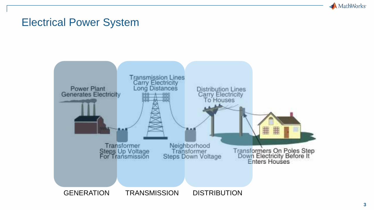
Electrical Power System
GENERATION TRANSMISSION DISTRIBUTION
4
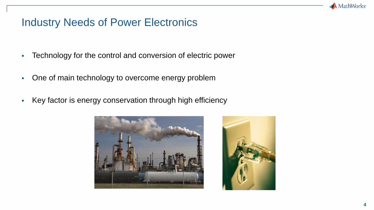
Industry Needs of Power Electronics
Technology for the control and conversion of electric power
One of main technology to overcome energy problem
Key factor is energy conservation through high efficiency
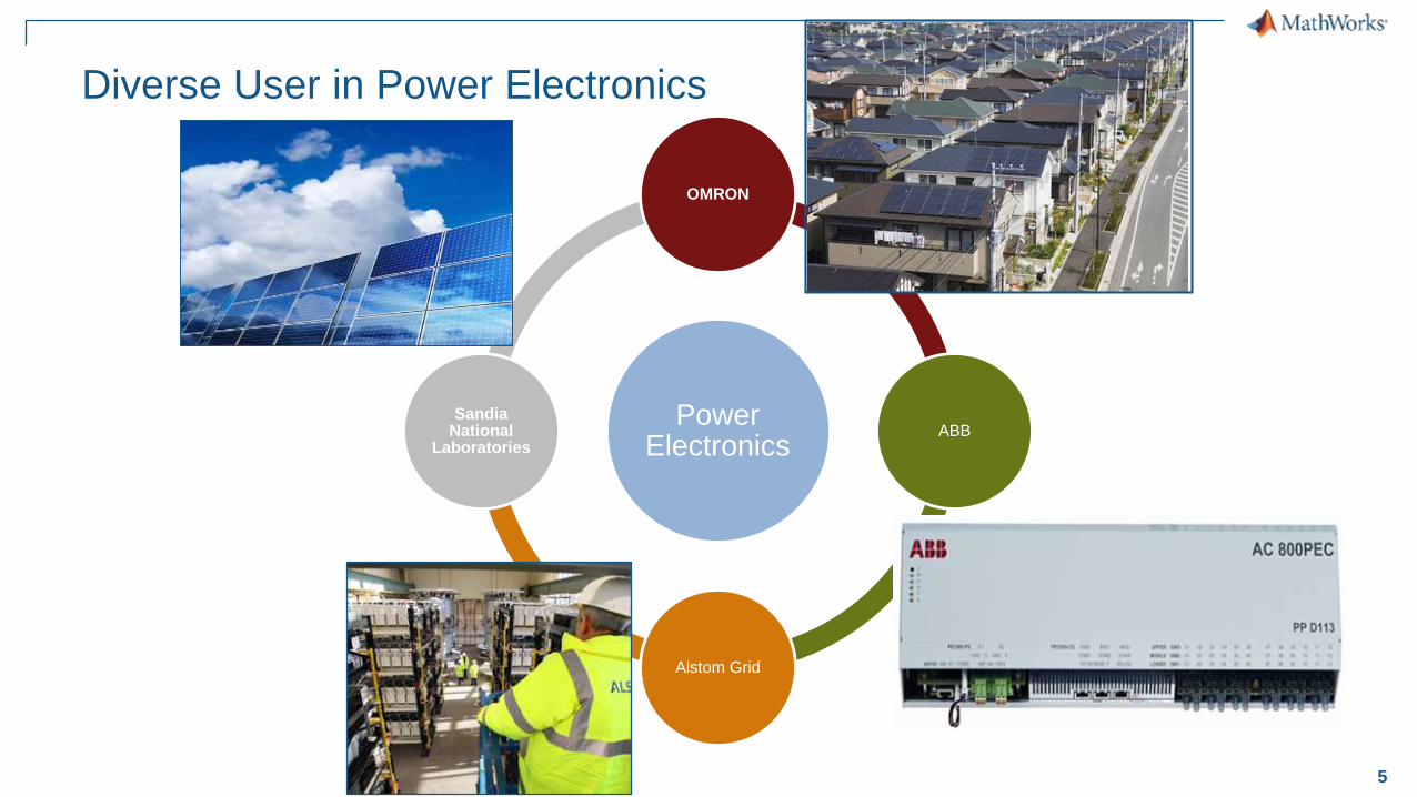
5
Power Electronics
OMRON
ABB
Alstom Grid
Sandia National
Laboratories
Diverse User in Power Electronics
6
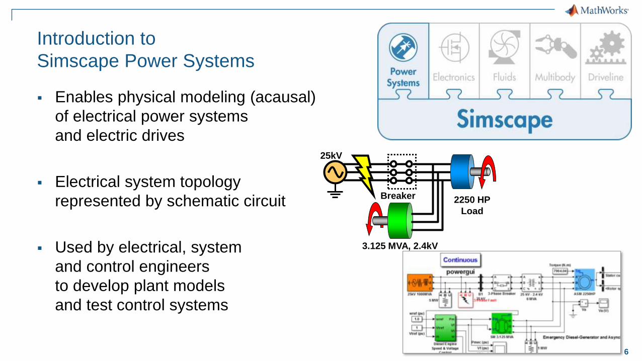
Introduction to
Simscape Power Systems
Enables physical modeling (acausal)
of electrical power systems
and electric drives
Electrical system topology
represented by schematic circuit
Used by electrical, system
and control engineers
to develop plant models
and test control systems
3.125 MVA, 2.4kV
25kV
2250 HP
Load
Breaker
7
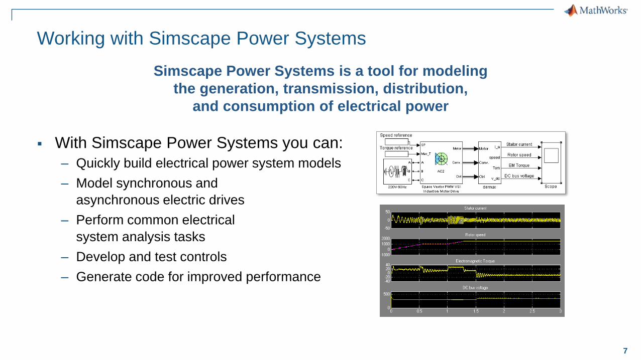
Working with Simscape Power Systems
With Simscape Power Systems you can:
– Quickly build electrical power system models
– Model synchronous and
asynchronous electric drives
– Perform common electrical
system analysis tasks
– Develop and test controls
– Generate code for improved performance
Simscape Power Systems is a tool for modeling
the generation, transmission, distribution,
and consumption of electrical power

8
MathWorks Investment in Simscape
More than 15 years of acausal modeling
Steady advances in breadth and depth
of libraries and capabilities
2-Phase Fluid
In Simscape
Thermal Liquid
In Simscape
Magnetics
In Simscape
Pneumatics
In Simscape
Simscape Language
Simscape
Electronics
Real
Gas
Simscape
Fluids
Thermal
Liquid
Discrete
Events
3-D Vis. Improvements
AutodeskTranslator
Ideal Switching
Algorithm Introduced
Electric Drives
Library Introduced
ProEngineer
Translator
SolidWorks
Translator
Simscape
Driveline
Simscape
Multibody
Simscape
Simscape
Power SystemsIntf. Elements
Editing Mode
1998 2000 2002 2004 2006 2008 2010 2012 2014 2016 2018
Zero Cross.
Statistics
Simscape
Logging
Local
Solver
Simscape-Based
Libraries
Model
Statistics
Thermal effects
optional ports
Simscape-Based
Libraries
Simscape-Based
Libraries
Variable
Viewer
Detailed
MOSFETs
Runtime
Parameters
Runtime
Parameters
Runtime
Parameters
9
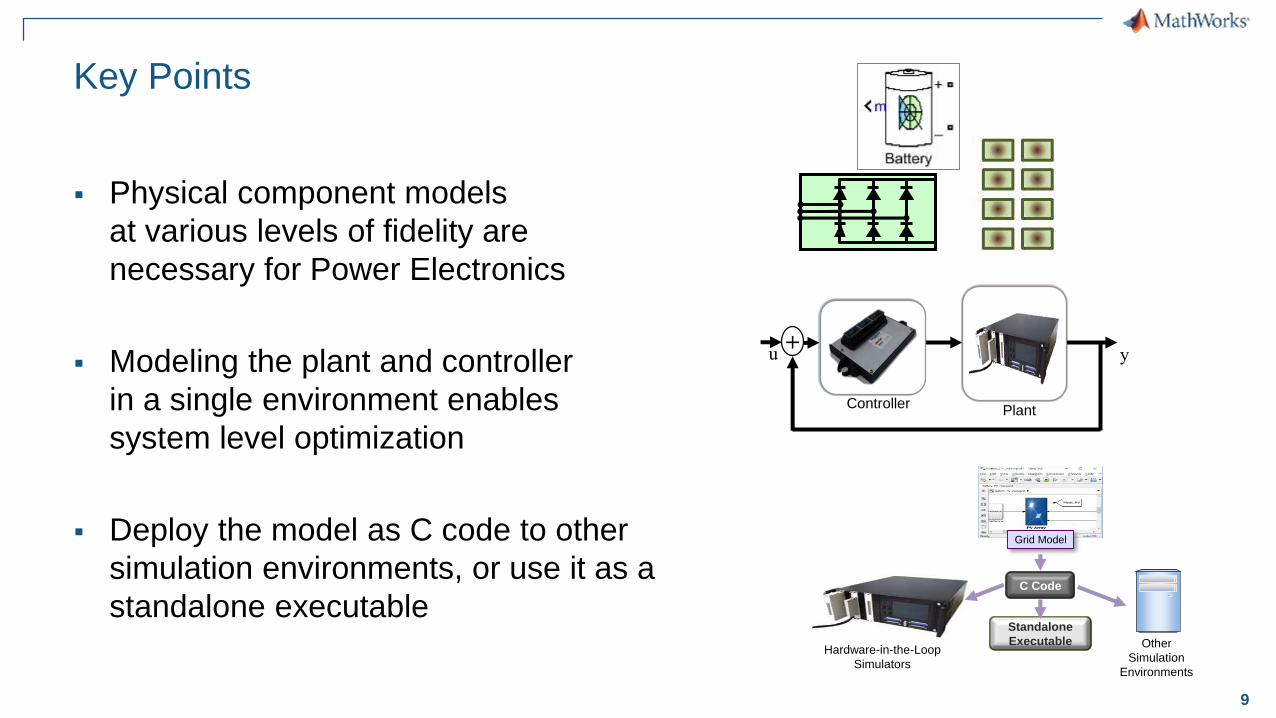
Key Points
Physical component models
at various levels of fidelity are
necessary for Power Electronics
Modeling the plant and controller
in a single environment enables
system level optimization
Deploy the model as C code to other
simulation environments, or use it as a
standalone executable
Plant
+u y
Controller
s1 s2
s3
System
Actu
ato
rs
Sen
so
rs
C Code
Hardware-in-the-Loop
Simulators
Standalone
Executable Other
Simulation
Environments
Grid Model
10
Agenda
Modeling electrical and electronic components
– Modeling Electrical Circuit : Buck Converter
– Battery Modeling using Simscape Power Systems
Designing control algorithms
Simulating in Real Time
Summary
11
Agenda
Modeling electrical and electronic components
– Modeling Electrical Circuit : Buck Converter
– Battery Modeling using Simscape Power Systems
Designing control algorithms
Simulating in Real Time
Summary
12
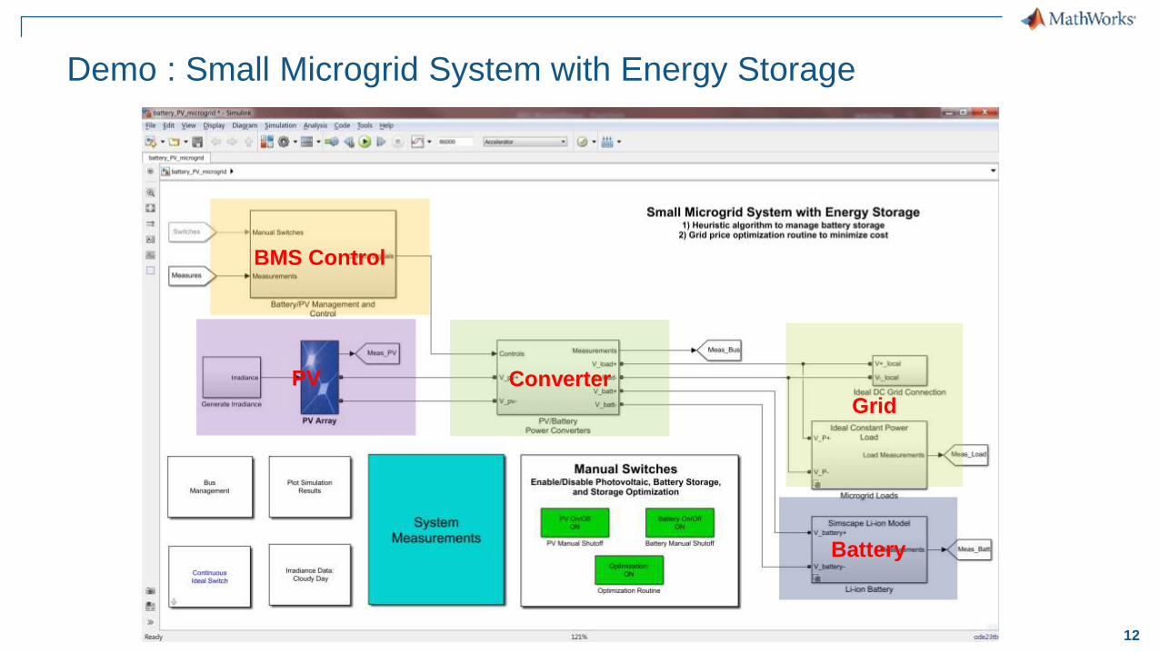
Demo : Small Microgrid System with Energy Storage
PV Converter
BMS Control
Battery
Grid
13
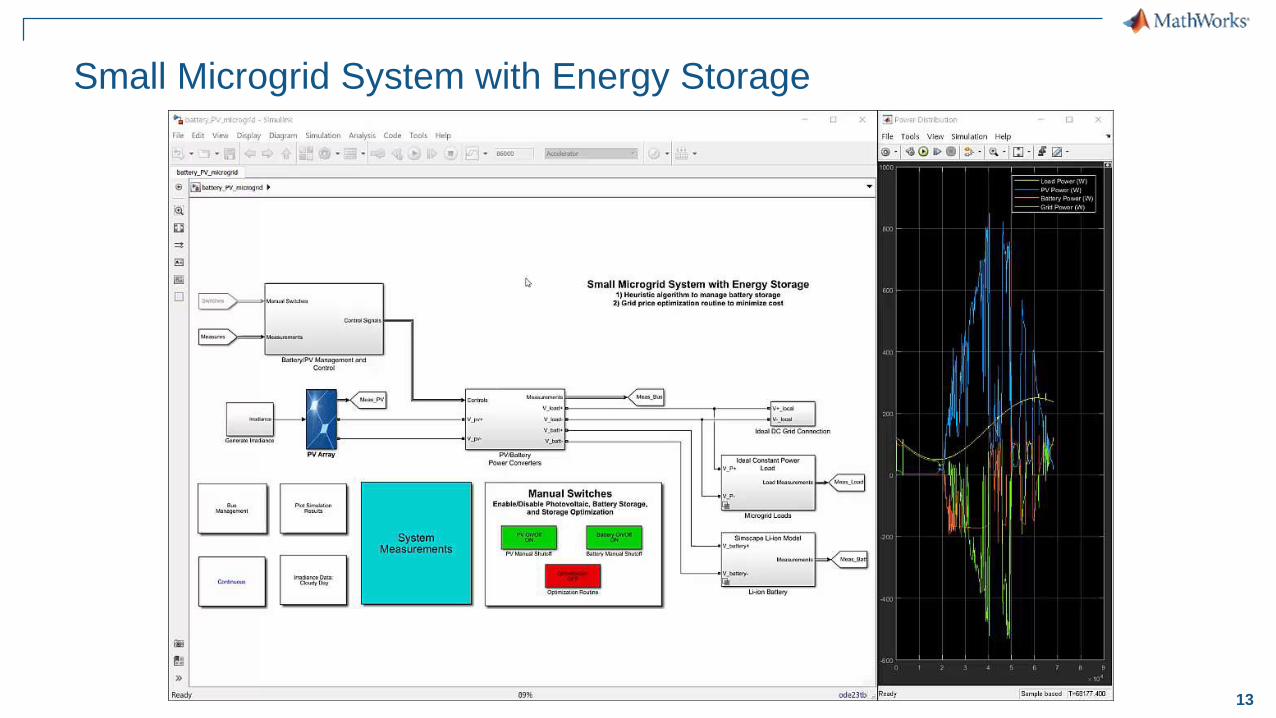
Small Microgrid System with Energy Storage
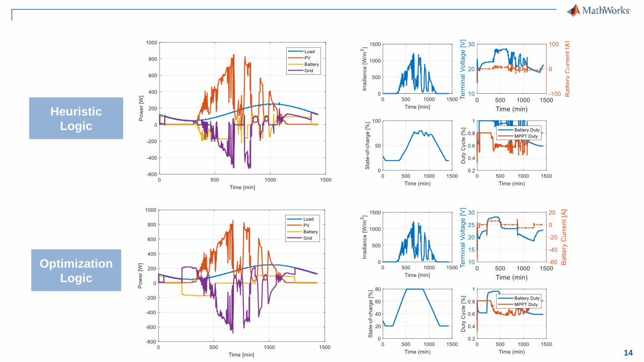
14
Heuristic
Logic
Optimization
Logic
15
Agenda
Modeling electrical and electronic components
– Modeling Electrical Circuit : Buck Converter
– Battery Modeling using Simscape Power Systems
Designing control algorithms
Simulating in Real Time
Summary
16
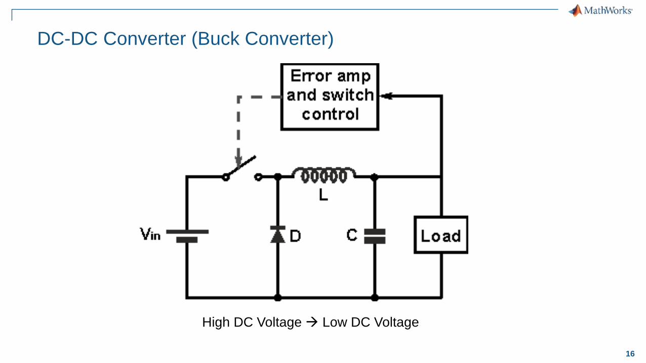
High DC Voltage Low DC Voltage
DC-DC Converter (Buck Converter)
17
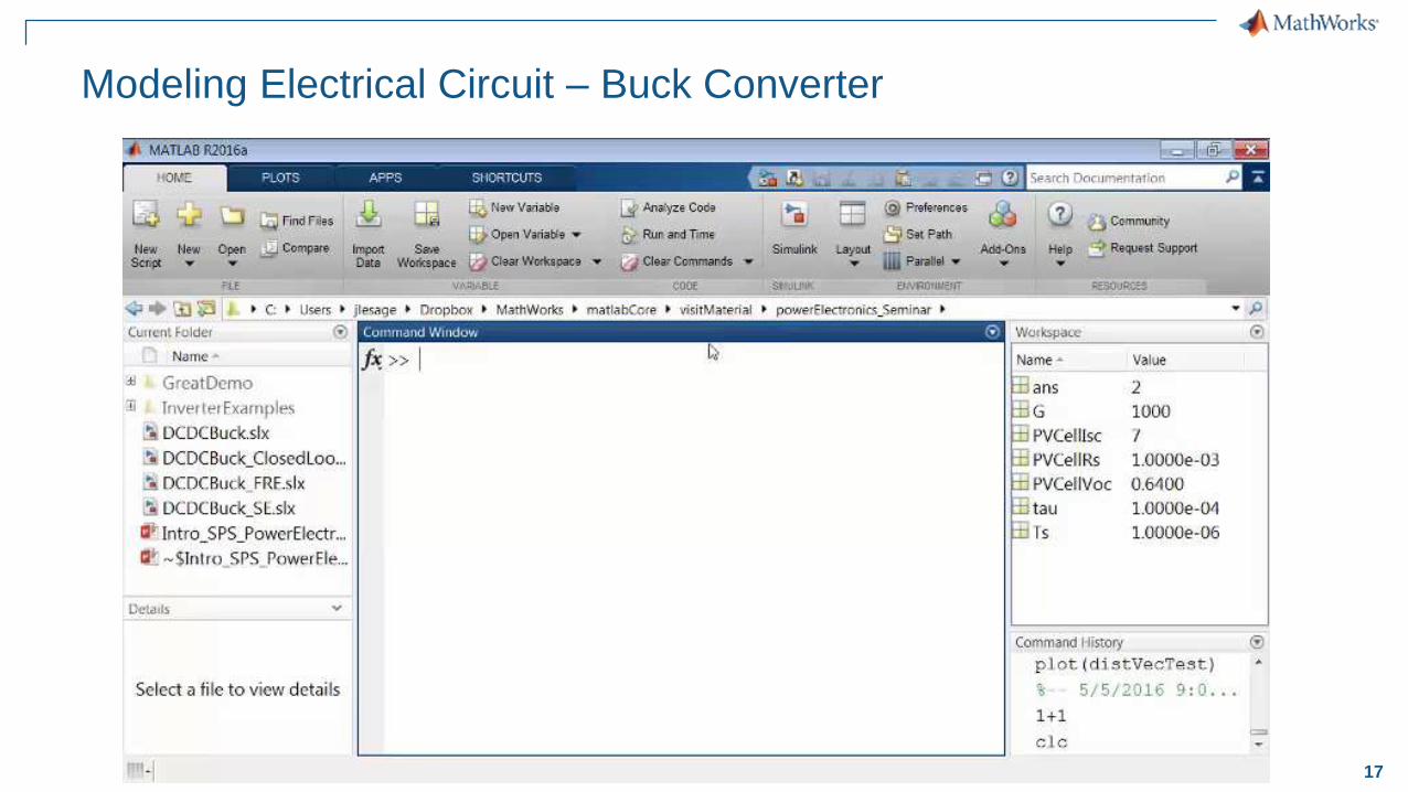
Modeling Electrical Circuit – Buck Converter
18
Agenda
Modeling electrical and electronic components
– Modeling Electrical Circuit : Buck Converter
– Battery Modeling using Simscape Power Systems
Designing control algorithms
Simulating in Real Time
Summary
19
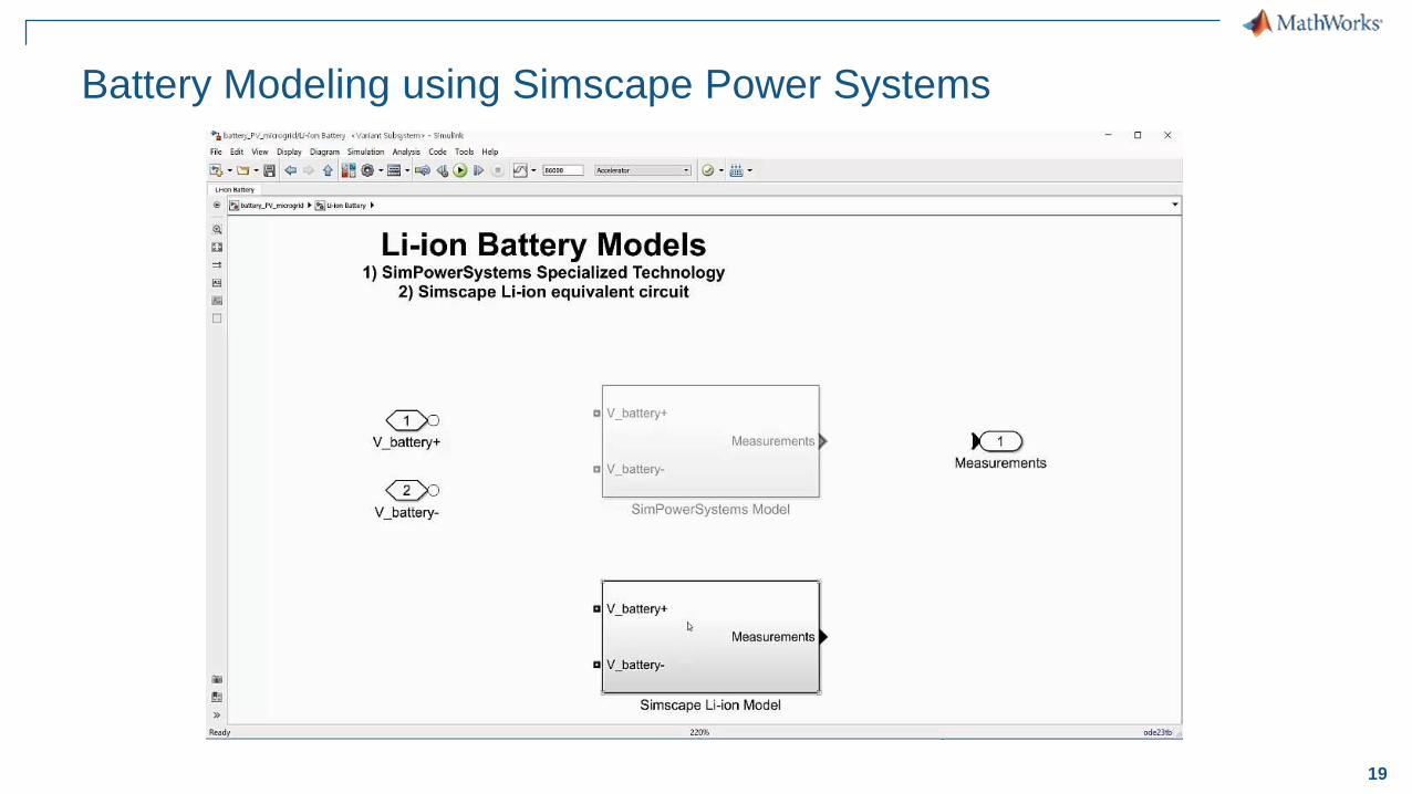
Battery Modeling using Simscape Power Systems
20
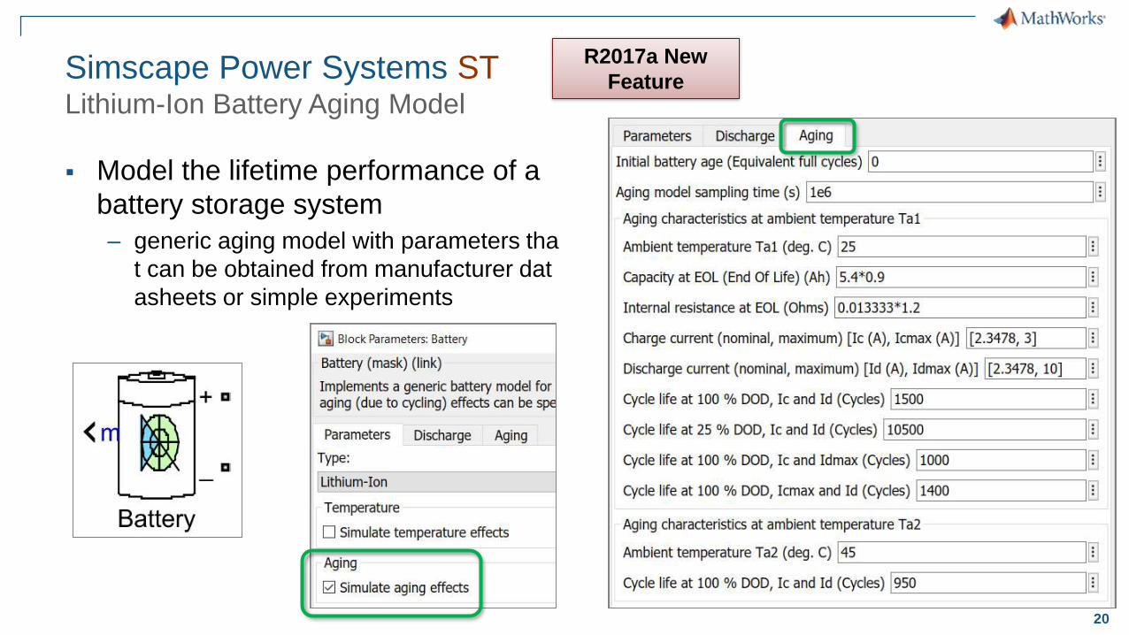
Simscape Power Systems STLithium-Ion Battery Aging Model
Model the lifetime performance of a
battery storage system
– generic aging model with parameters tha
t can be obtained from manufacturer dat
asheets or simple experiments
R2017a New
Feature
21
Agenda
Modeling electrical and electronic components
– Modeling Electrical Circuit : Buck Converter
– Battery Modeling using Simscape Power Systems
Designing control algorithms
Simulating in Real Time
Summary
22
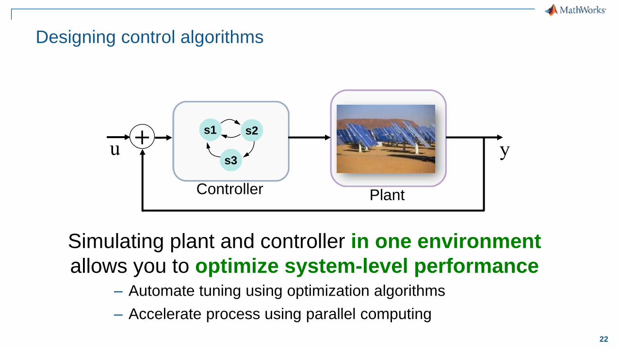
Simulating plant and controller in one environment
allows you to optimize system-level performance– Automate tuning using optimization algorithms
– Accelerate process using parallel computing
Designing control algorithms
Plant
+u y
Controller
s1 s2
s3
23
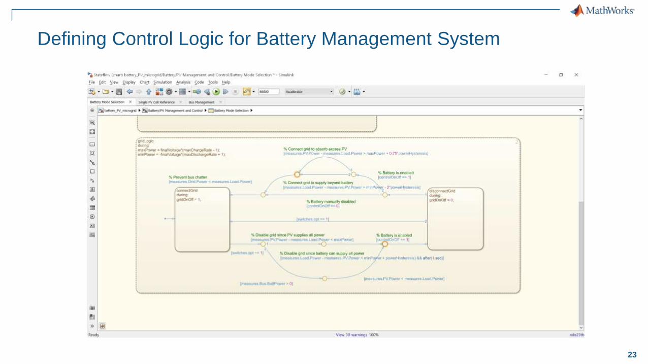
Defining Control Logic for Battery Management System

24
Defining Control Logic for Battery Management System
Adapted from: Smart EnergySystems Website
http://www.smart-energy.ag/products/ac-gekoppelte-speicherlosung-smartenergy-ac/?lang=en
25
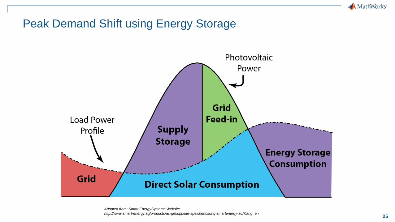
Peak Demand Shift using Energy Storage
Adapted from: Smart EnergySystems Website
http://www.smart-energy.ag/products/ac-gekoppelte-speicherlosung-smartenergy-ac/?lang=en
26
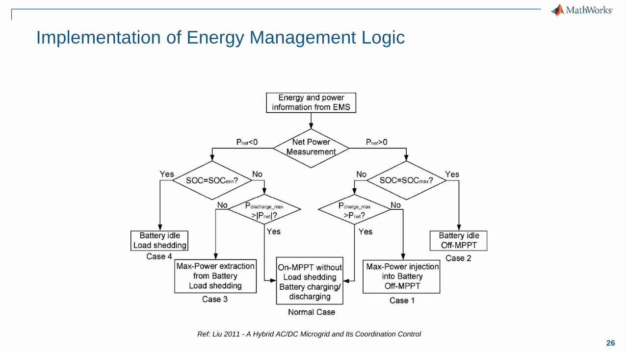
Implementation of Energy Management Logic
Ref: Liu 2011 - A Hybrid AC/DC Microgrid and Its Coordination Control

27
Factoring in Variable Electricity Cost
Adapted from: Smart EnergySystems Website
http://www.smart-energy.ag/products/ac-gekoppelte-speicherlosung-smartenergy-ac/?lang=en
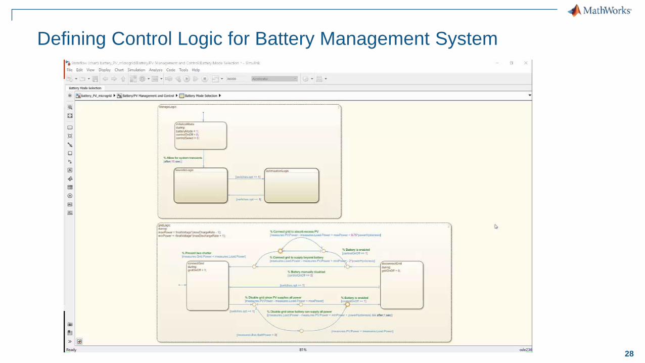
28
Defining Control Logic for Battery Management System
29
Agenda
Modeling electrical and electronic components
– Modeling Electrical Circuit : Buck Converter
– Battery Modeling using Simscape Power Systems
Designing control algorithms
Simulating in Real Time
Summary
30
System
Model
System
Specification
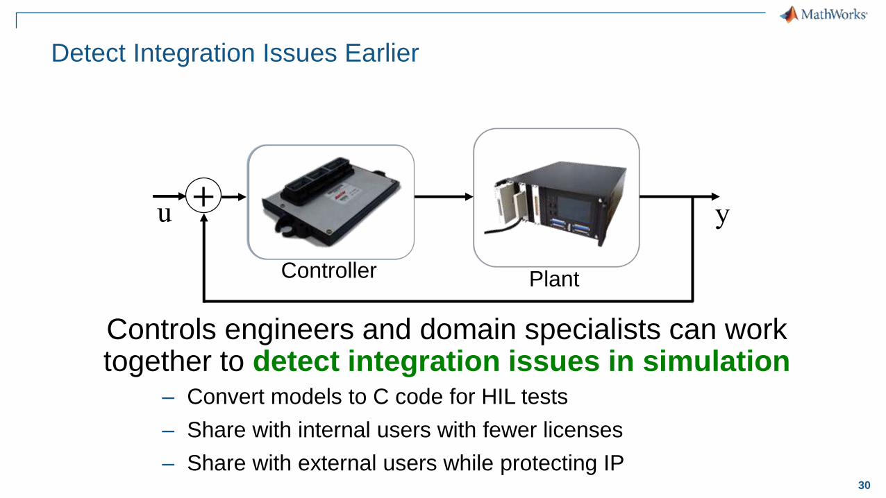
Detect Integration Issues Earlier
Plant
+u y
Controller
s1 s2
s3
Controls engineers and domain specialists can work together to detect integration issues in simulation
– Convert models to C code for HIL tests
– Share with internal users with fewer licenses
– Share with external users while protecting IP
System
Ac
tua
tors
Se
ns
ors
31
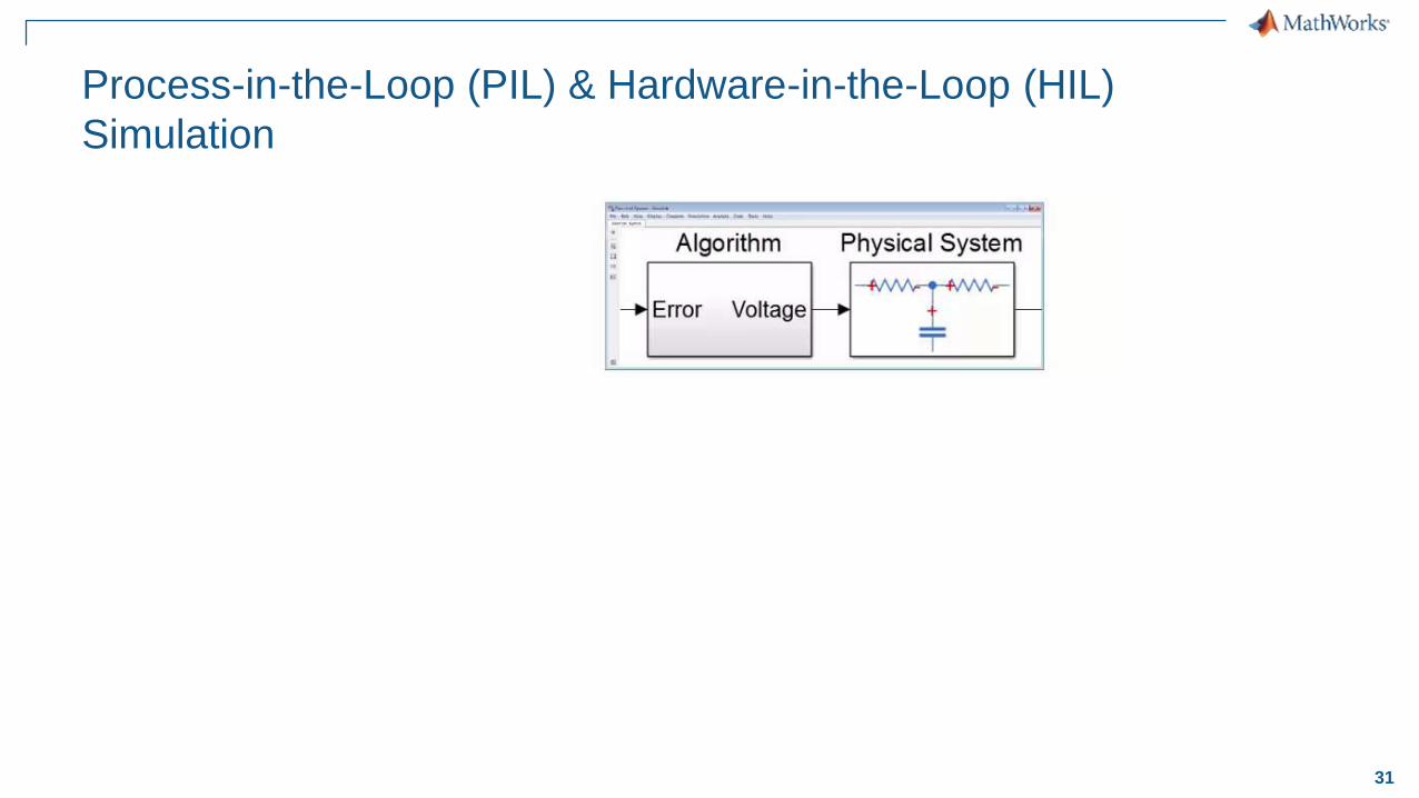
Process-in-the-Loop (PIL) & Hardware-in-the-Loop (HIL)
Simulation
32
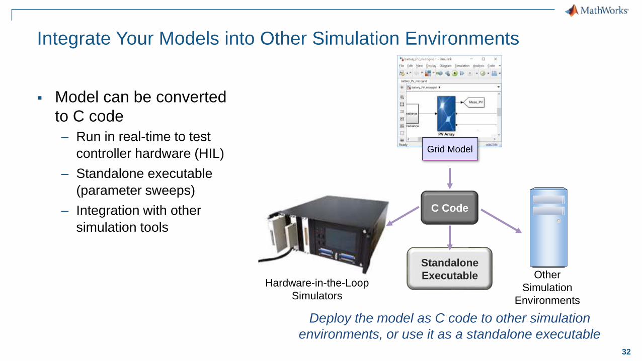
Integrate Your Models into Other Simulation Environments
Model can be converted
to C code
– Run in real-time to test
controller hardware (HIL)
– Standalone executable
(parameter sweeps)
– Integration with other
simulation tools
C Code
Hardware-in-the-Loop
Simulators
Standalone
Executable
Deploy the model as C code to other simulation
environments, or use it as a standalone executable
Other
Simulation
Environments
Grid Model

33
Summary
Physical component models
at various levels of fidelity are
necessary for Power Electronics
Modeling the plant and controller
in a single environment enables
system level optimization
Deploy the model as C code to other
simulation environments, or use it as a
standalone executable
Plant
+u y
Controller
s1 s2
s3
System
Actu
ato
rs
Sen
so
rs
C Code
Hardware-in-the-Loop
Simulators
Standalone
Executable Other
Simulation
Environments
Grid Model
34
Q&A