Embed Size (px)
Citation preview
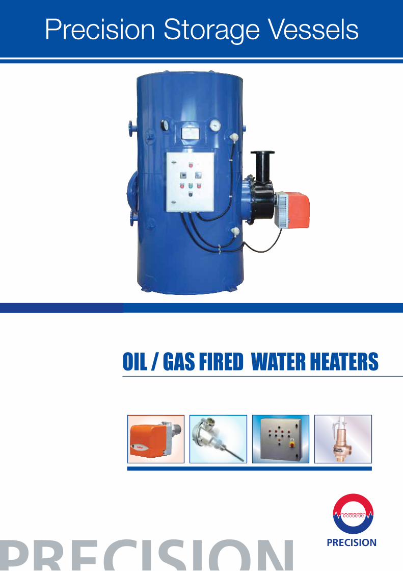
OIL / GAS FIRED WATER HEATERS
Precision Storage Vessels
4
CARATTERISTICHE TECNICO-FUNZIONALI
di focolare.
pressione del combustibile tramite ugello.
combustione tramite la regolazione dell’aria comburente e della testa di combustione.
di sfilare il gruppo di polverizzazione senza smontare il bruciatore dalla caldaia.
dell’aria.
(combustibile di origine vegetale), il bruciatore deve essere costruito con componenti specifici: tubi flessibili, filtro linea e pompa.
pressione e valvola di intercettazione del combustibile.
e controllo del bruciatore secondo norma europea EN230.
tramite fotoresistenza.
elettrica e termostatica del bruciatore.
protezione IP40.
plastico insonorizzante con materassino fonoassorbente.
Caratteristiche
4
1 flangia e 1 guarnizione isolante per il fissaggio alla caldaia, 2 tubi flessibili, 1 filtro di linea e 1 ugello.
CARATTERISTICHE COSTRUTTIVEIl bruciatore risulta composto da:
d’alluminio.
prestazioni.
-tivo per la regolazione della portata d’aria. Serranda a chiusura automati-ca (escluso BTL 26).
scorrevole per adattare la sporgenza della testa ai vari tipi di generatori di calore.
completa di boccaglio e disco fiamma in acciaio.
l’azionamento del ventilatore e della pompa.
SERIE BTL...
Conformi alla:Direttiva E.M.C. 89/336/CEE
Direttiva L.V. 73/23/CEENorma di riferimento: EN267
Direct Oil / Gas Fired water heaters are the best solution where fuel fired hot water system can be used. Wide range output can be achieved in this water heaters. Fully automatic burners are used for safe operation.
Storage CalorifierStorage calorifiers are sized to meet the peak demand period with recovery periods varying from one to four hours.
StandardsASME Code construction:- All tanks are constructed in accordance with ASME code section IV Stamped and labeled for 125 PSI (8.6 BAR) as Standard.
Precision also design Oil/Gas calorifiers as per British Standard BS 853:1996, BS 5500:1997 or in accordance with Art 3.3 of the European Directive EEC/97/23 for pressure equipment.
Advantages
• Efficiency is maintained throughout the range of load. Even at part load all energy is converted into heat.
• Space requirements are minimum. Separate boiler not required.
• Installation is simplified.
• The calorifier can be installed with minimum electric load.
• Maintenance is kept to a minimum.
• Low nox burners are used.
• Fuel efficient burners are used.
• Diesel oil, Natural Gas, LPG and Propane can be used.
Hot Water Oil / Gas KW Shell Material Configuration Capacity
Oil / Gas Fired Water Heaters
Eg: HWO30PCV1000L
HW O/G 30 PC V 1000 L
2
O Input LitresV-VerticalH-Horizontal
PC-Precision Coat
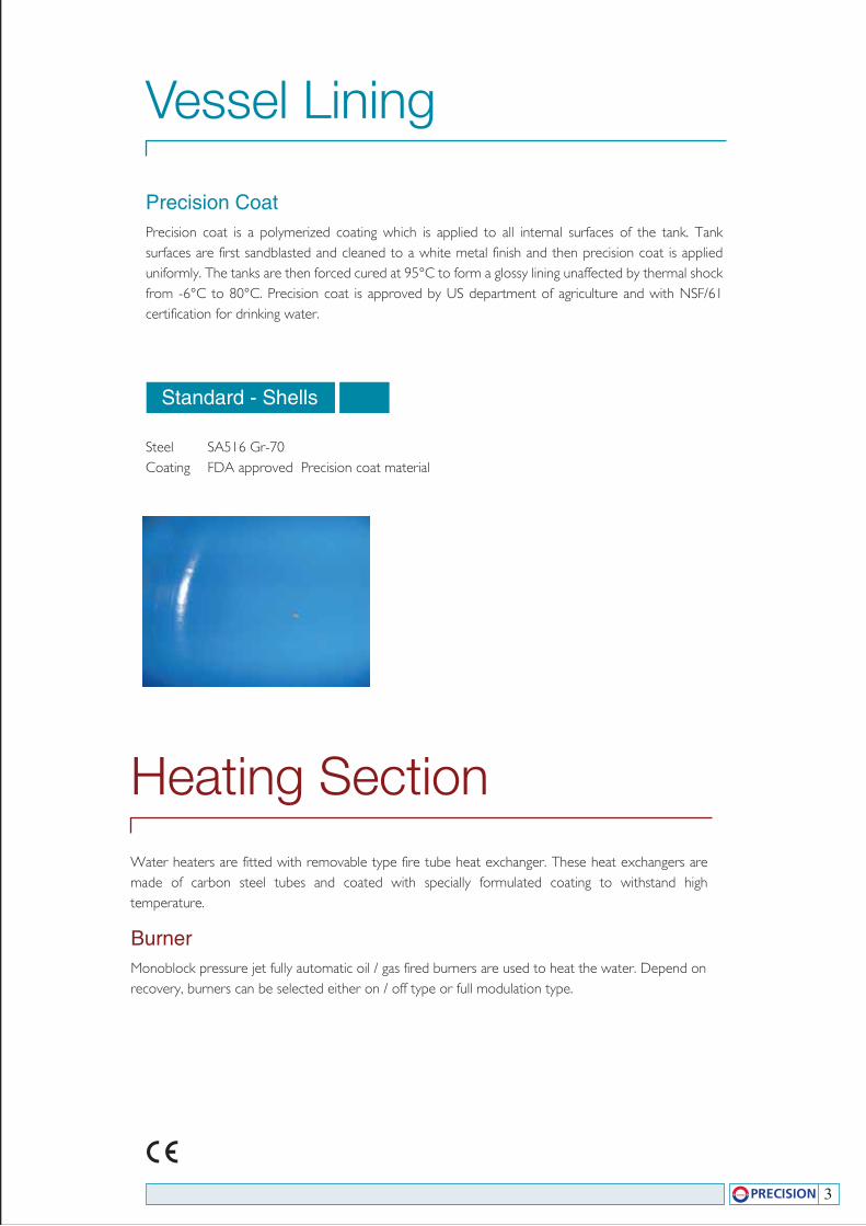
Precision CoatPrecision coat is a polymerized coating which is applied to all internal surfaces of the tank. Tank surfaces are first sandblasted and cleaned to a white metal finish and then precision coat is applied uniformly. The tanks are then forced cured at 95°C to form a glossy lining unaffected by thermal shock from -6°C to 80°C. Precision coat is approved by US department of agriculture and with NSF/61 certification for drinking water.
Vessel Lining
Standard - Shells
Steel SA516 Gr-70Coating FDA approved Precision coat material
3
Water heaters are fitted with removable type fire tube heat exchanger. These heat exchangers are made of carbon steel tubes and coated with specially formulated coating to withstand high temperature.
BurnerMonoblock pressure jet fully automatic oil / gas fired burners are used to heat the water. Depend on recovery, burners can be selected either on / off type or full modulation type.
Heating Section
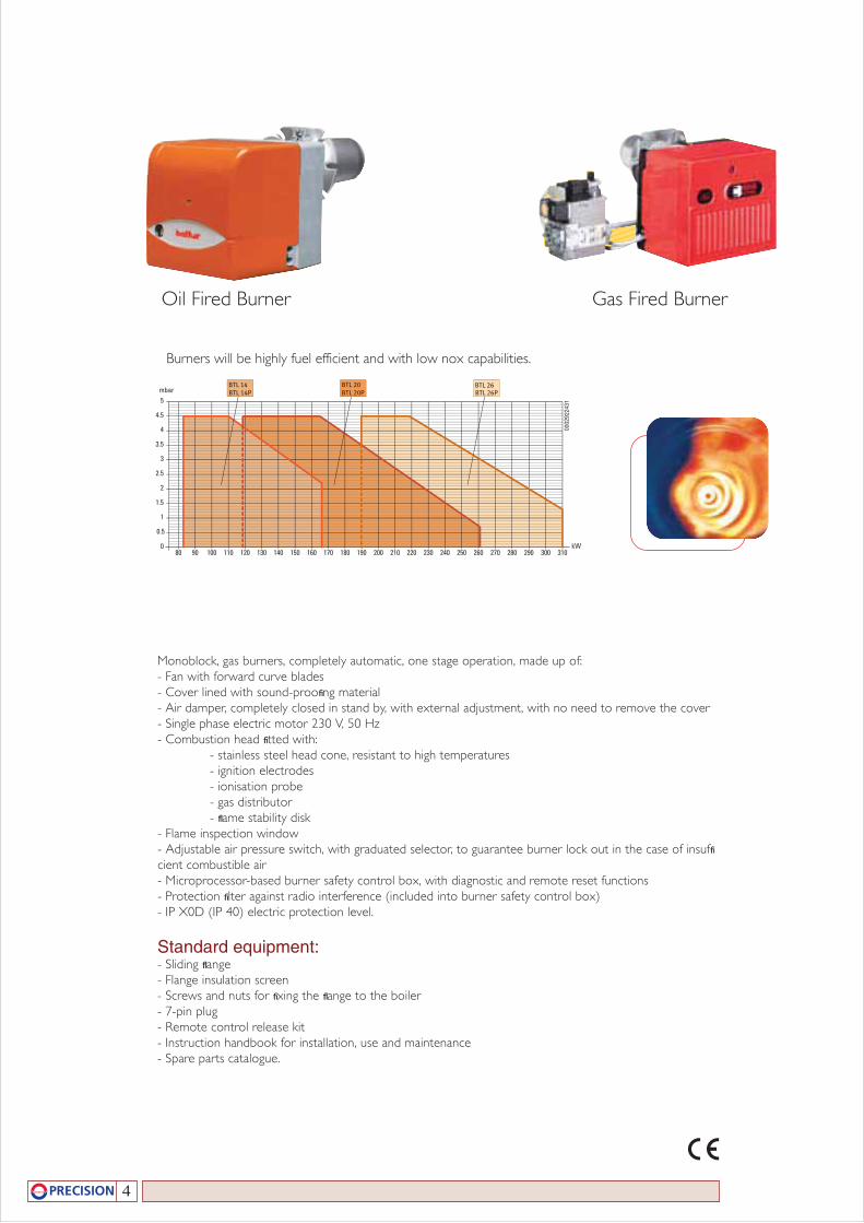
Monoblock, gas burners, completely automatic, one stage operation, made up of:- Fan with forward curve blades- Cover lined with sound-proofi ng material- Air damper, completely closed in stand by, with external adjustment, with no need to remove the cover- Single phase electric motor 230 V, 50 Hz- Combustion head fi tted with: - stainless steel head cone, resistant to high temperatures - ignition electrodes - ionisation probe - gas distributor - fl ame stability disk- Flame inspection window- Adjustable air pressure switch, with graduated selector, to guarantee burner lock out in the case of insuffi cient combustible air- Microprocessor-based burner safety control box, with diagnostic and remote reset functions- Protection fi lter against radio interference (included into burner safety control box)- IP X0D (IP 40) electric protection level.
Standard equipment:- Sliding fl ange- Flange insulation screen- Screws and nuts for fi xing the fl ange to the boiler- 7-pin plug- Remote control release kit- Instruction handbook for installation, use and maintenance- Spare parts catalogue.
Burners will be highly fuel efficient and with low nox capabilities.
4
Oil Fired Burner Gas Fired Burner
Gammaprodotti
2
5
4.5
mbar
4
3.5
3
2.5
0
2
1.5
1
0.5
0002
9224
31
31030029028027026025024023022021020019018017016015014013012011090 10080kW
BTL 26BTL 20BTL 20P BTL 26P
BTL 14BTL 14P
0002
9213
35/1
-T04
50 100 150 200 250 300 350 400 450
mbar
3.5
4.5
4
3
2.5
2
1.5
1
0.5
0 kW
SPARK 35-35 W
I diagrammi hanno carattere indicativo e sono stati realizzati su caldaie di prova secondo le norme vigenti. In pratica possono verificarsi scostamenti determinati dai seguenti fattori:a) Capacità o meno del bruciatore
di superare la sovrapressione all’accensione (non strettamente legata a quella di regime) che varia da caldaia a caldaia.
b) Elevato carico termico del focolare (rapporto tra la potenza termica del focolare ed il relativo volume - kcal/h/m3) per cui il ventilatore del bruciatore potrebbe non essere in grado di consentire l’utilizzazione di tutto il campo di lavoro.
BRUCIATORI DI GASOLIOMONOSTADIO
BTL 14 35610010 83,0 166 7 14 1,5 1N AC 50Hz 230V 0,18 1) BTL 20 35630010 118,6 261 10 22 1,5 1N AC 50Hz 230V 0,18 1) BTL 26 35650010 190,0 310 16 26 1,5 1N AC 50Hz 230V 0,25 SPARK 35 W 3070010 178,0 391 15 33 1,5 1N AC 50Hz 230V 0,37 3) SPARK 35 3071010 178,0 391 15 33 1,5 1N AC 50Hz 230V 0,37 3)
NOTE:1) Dotato di dispositivo chiusura aria.3) Dotato di insonorizzatore.*) Potere calorifico inferiore gasolio: Hi = 42,70 MJ/kg = 10200 kcal/kg.
Modello
Potenza termica
min max kW kW
Potenzamotore
kW
AlimentazioneelettricaCodice
Portata *)
min max kg/h kg/h
NoteVisc.
combust.°E 20 °C
COMBUSTION HEAD
The combustion head in Riello 40 GS burners is the result of aninnovative design, which allows combustion with low pollutingemissions, while being easy to adapt to all the various types ofboilers and combustion chambers.
Combustion head Flange
Simple adjustment allowsthe internal geometry ofthe combustion head tobe adapted to the burneroutput.
VENTILATION
The different ventilation circuits always ensure low noise levelswith high performance of pressure and air delivery, inspite of theircompact size.The burners are fitted with an adjustable air pressure switch,conforming to EN 676 standards.
Air suction Air pressure switch
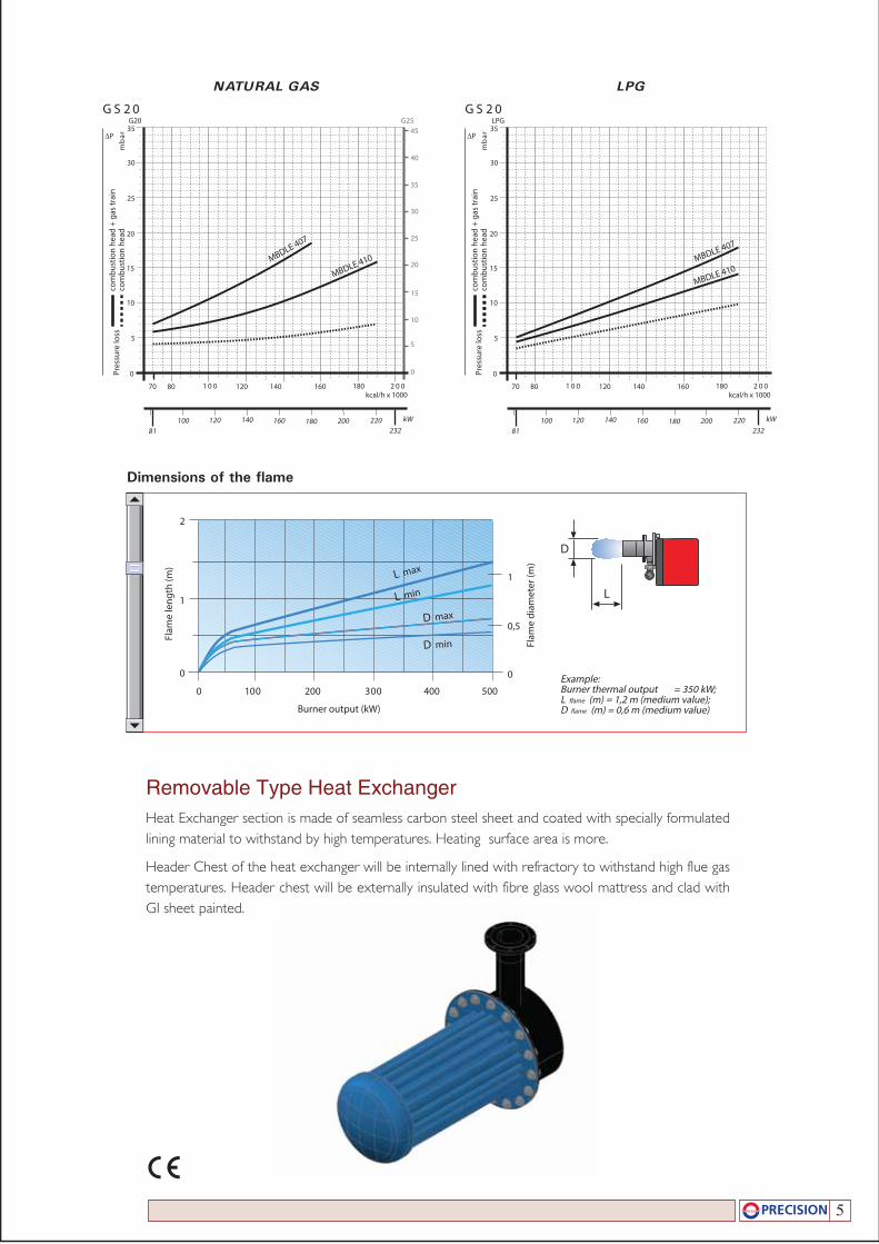
Dimensions of the flame
Example:Burner thermal output = 350 kW;L flame (m) = 1,2 m (medium value);D flame (m) = 0,6 m (medium value)Burner output (kW)
Flam
e le
ng
th (
m)
Flam
e d
iam
eter
(m
)
0 200
1
100 300
2
400 500
0 0
0,5
1
D
L
L max
L min
D max
D min
9
4
CARATTERISTICHE TECNICO-FUNZIONALI
di focolare.
pressione del combustibile tramite ugello.
combustione tramite la regolazione dell’aria comburente e della testa di combustione.
di sfilare il gruppo di polverizzazione senza smontare il bruciatore dalla caldaia.
dell’aria.
(combustibile di origine vegetale), il bruciatore deve essere costruito con componenti specifici: tubi flessibili, filtro linea e pompa.
pressione e valvola di intercettazione del combustibile.
e controllo del bruciatore secondo norma europea EN230.
tramite fotoresistenza.
elettrica e termostatica del bruciatore.
protezione IP40.
plastico insonorizzante con materassino fonoassorbente.
Caratteristiche
4
1 flangia e 1 guarnizione isolante per il fissaggio alla caldaia, 2 tubi flessibili, 1 filtro di linea e 1 ugello.
CARATTERISTICHE COSTRUTTIVEIl bruciatore risulta composto da:
d’alluminio.
prestazioni.
-tivo per la regolazione della portata d’aria. Serranda a chiusura automati-ca (escluso BTL 26).
scorrevole per adattare la sporgenza della testa ai vari tipi di generatori di calore.
completa di boccaglio e disco fiamma in acciaio.
l’azionamento del ventilatore e della pompa.
SERIE BTL...
Conformi alla:Direttiva E.M.C. 89/336/CEE
Direttiva L.V. 73/23/CEENorma di riferimento: EN267
FUEL SUPPLY
GAS TRAIN
The burners are set for gas supply from either the rightor left hand sides.
Depending on the fuel output and the available pressurein the supply line, you should check the correct gas trainto be adapted to the system requirements.
The gas train is Multibloc type, containing the maincomponents in a single unit.Except for the MBC 65 DLE model, a valve seal control(as accessory) can be fitted to the Multibloc gas trains.
The MBC 65 DLE Multibloc gas train can be fitted onlyto the left of the burner.
MBDLE 405 - 407 - 410
L1 L
LEAK DETECTION CONTROL DEVICE
MULTIBLOC
MBC 65 DLE
L1 L
MULTIBLOC
1
2
3
4
5
6
7
8
9
10
11
12
13
14
15
P1
P2
P3
L
L1
Gas delivery pipe
Manual valve
Vibration damping joint
Gas pressure gauge
Filter
Gas pressure switch
Safety solenoid
Adjustment solenoid:firing delivery adjustment (rapid opening)maximum delivery adjustment (slow opening)
Pressure regulator
Leak detection control device for valves 7 and 8 (accessory)
Gas train-burner adapter
Burner
Shutter with adjustment screws
Pressure regulator setting device
Regulation solenoid
Combustion head pressure
Upstream pressure from the filter
Upstream pressure from the control valve
Gas train supplied separately
To be performed by the installer
11
5
96
7 8
12
3
4
P2
10
12
P1
5
67 15
12
3
4
P2 P3
13
13
14
9
11 12
P1
4
5
Removable Type Heat ExchangerHeat Exchanger section is made of seamless carbon steel sheet and coated with specially formulated lining material to withstand by high temperatures. Heating surface area is more.
Header Chest of the heat exchanger will be internally lined with refractory to withstand high flue gas temperatures. Header chest will be externally insulated with fibre glass wool mattress and clad with GI sheet painted.
GPLSAG LARUTAN
02SG02SG
∆P
com
bust
ion
head
+ g
as tr
ain
com
bust
ion
head
Pres
sure
loss
mb
ar ∆P
com
bust
ion
head
+ g
as tr
ain
com
bust
ion
head
Pres
sure
loss
mb
ar
MBDLE 410
kW232
120
0
10081
200
5
10
15
20
25
140 180160 220
kcal/h x 100000200180 120 140 18016070
30
35G20 G25
0
5
15
25
30
35
10
40
45
MBDLE 407
MBDLE 410
kW232
120
0
10081
200
5
10
15
20
25
140 180160 220
kcal/h x 100000200180 120 140 18016070
30
35LPG
MBDLE 407
20
Dimensions of the flame
Example:Burner thermal output = 350 kW;L �ame (m) = 1,2 m (medium value);D �ame (m) = 0,6 m (medium value)Burner output (kW)
Flam
e le
ngth
(m)
Flam
e di
amet
er (m
)
0 200
1
003001
2
400 500
0 0
0,5
1
D
L
L max
L min
D max
D min
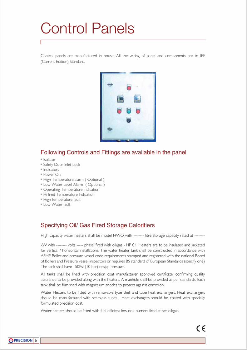
Control panels are manufactured in house. All the wiring of panel and components are to IEE (Current Edition) Standard.
Control Panels
Following Controls and Fittings are available in the panel• Isolator• Safety Door Inlet Lock• Indicators• Power On• High Temperature alarm ( Optional )• Low Water Level Alarm ( Optional )• Operating Temperature Indication• Hi limit Temperature Indication• High temperature fault• Low Water fault
6
Specifying Oil/ Gas Fired Storage Calorifiers
High capacity water heaters shall be model HWO with -------- litre storage capacity rated at --------
kW with -------- volts ----- phase, fired with oil/gas - HP 04. Heaters are to be insulated and jacketed for vertical / horizontal installations. The water heater tank shall be constructed in accordance with ASME Boiler and pressure vessel code requirements stamped and registered with the national Board of Boilers and Pressure vessel inspectors or requires BS standard of European Standards (specify one) The tank shall have 150Psi (10 bar) design pressure.
All tanks shall be lined with precision coat manufacturer approved certificate, confirming quality assurance to be provided along with the heaters. A manhole shall be provided as per standards. Each tank shall be furnished with magnesium anodes to protect against corrosion.
Water Heaters to be fitted with removable type shell and tube heat exchangers. Heat exchangers should be manufactured with seamless tubes. Heat exchangers should be coated with specially formulated precision coat.
Water heaters should be fitted with fuel efficient low nox burners fired either oil/gas.
7
The water heaters to be fitted with factory fitted shell mounted pre-wired control panel with Isolator, Safety Door Inter Lock, Test/On/Auto switches, Illuminating Indication for power on, High Temperature fault, Low Water Fault, Thermostatic control shall comprise of a thermostatic switch for operating and high limit. Temperature display, low water cut out to be mounted on the shell.
The control panel should have 3 volt free contacts to give signals for Low Water /Power On/Off/Temperature and for external alarm.
The tank to be fully lagged with 50mm thick fibre glass mattress and clad with in a G.I sheets painted with two coat gloss blue paint.
The tank shall be fitted with screwed/flanged connection for safety valve, thermostats, Pressure gauge. The water heaters shall be factory mounted, wired and tested.
Selection & Sizing
Solution
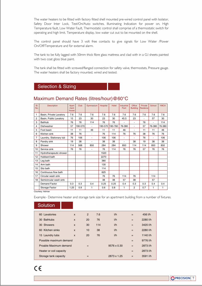
Sl. Description Apart Club Gymnasium Hospital Hotel industrial Office Private School YMCA No. ment Pant Building Residence house
1 Basin, Private Lavatory 7.6 7.6 7.6 7.6 7.6 7.6 7.6 7.6 7.6 7.6
2 Basin, Public Lavatory 15 23 30 23 30 45.5 23 - 57 30
3 Bathtub 76 76 114 76 76 - - 76 - 114
4 Dishwasher 57 190-570 - 190-570 190-760 76-380 - 57 76-380 76-380
5 Foot basin 11 11 46 11 11 46 - 11 11 46
6 Kitchen sink 38 76 - 76 114 76 76 38 76 76
7 Laundry, Stationary tub 76 106 - 106 106 - - 76 - 106
8 Pandry sink 19 38 - 38 38 - 38 19 38 38
9 Shower 114 568 850 284 284 850 114 114 850 850
10 Service sink 76 76 - 76 114 76 76 57 76 76
11 Hydrotherapeutic shower 1520
12 Hubbard bath 2270
13 Leg bath 380
14 Arm bath 130
15 Sitz bath 114
16 Continuous flow bath 625
17 Circular wash sink 76 76 114 76 114
18 Semicircular wash sink 38 38 57 38 57
Demand Factor 0.3 0.3 0.4 0.25 0.25 0.4 0.3 0.3 0.4 0.4
Storage Factor 1.25 0.9 1 0.6 0.8 1 2 0.7 1 1
Maximum Demand Rates (litres/hour)@60°C
Courtesy: Ashrae
Example:- Determine heater and storage tank size for an apartment building from a number of fixtures.
60 Lavatories x 2 7.6 l/h = 456 l/h
30 Bathtubs x 20 76 l/h = 2280 l/h
30 Showers x 30 114 l/h = 3420 l/h
60 Kitchen sinks x 10 38 l/h = 2280 l/h
15 Laundry tubs x 20 76 l/h = 1140 l/h
Possible maximum demand = 9776 l/h
Proable Maximum demand = 9576 x 0.30 = 2873 l/h
Heater or coil capacity = 2873 l/h
Storage tank capacity = 2873 x 1.25 = 3591 l/h
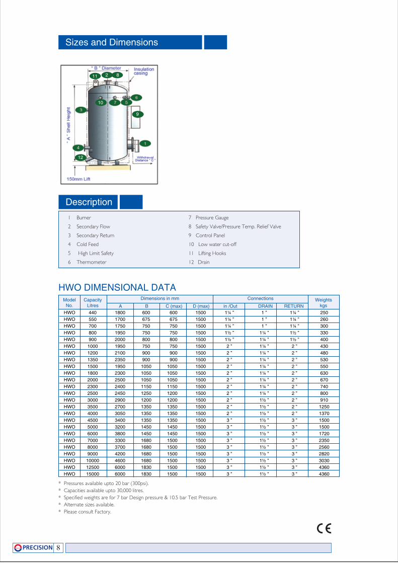
Sizes and Dimensions
Description1 Burner
2 Secondary Flow
3 Secondary Return
4 Cold Feed
5 High Limit Safety
6 Thermometer
ModelNo.
HWO 440 1800 600 600 1500 1¼ ” 1 ” 1¼ ” 250 HWO 550 1700 675 675 1500 1¼ ” 1 ” 1¼ ” 260 HWO 700 1750 750 750 1500 1¼ ” 1 ” 1¼ ” 300 HWO 800 1950 750 750 1500 1½ ” 1¼ ” 1½ ” 330 HWO 900 2000 800 800 1500 1½ ” 1¼ ” 1½ ” 400 HWO 1000 1950 750 750 1500 2 ” 1¼ ” 2 ” 430 HWO 1200 2100 900 900 1500 2 ” 1¼ ” 2 ” 480 HWO 1350 2350 900 900 1500 2 ” 1¼ ” 2 ” 530 HWO 1500 1950 1050 1050 1500 2 ” 1¼ ” 2 ” 550 HWO 1800 2300 1050 1050 1500 2 ” 1¼ ” 2 ” 630 HWO 2000 2500 1050 1050 1500 2 ” 1¼ ” 2 ” 670 HWO 2300 2400 1150 1150 1500 2 ” 1¼ ” 2 ” 740 HWO 2500 2450 1250 1200 1500 2 ” 1¼ ” 2 ” 800 HWO 3000 2900 1200 1200 1500 2 ” 1½ ” 2 ” 910 HWO 3500 2700 1350 1350 1500 2 ” 1½ ” 2 ” 1250 HWO 4000 3050 1350 1350 1500 2 ” 1½ ” 2 ” 1370 HWO 4500 3400 1350 1350 1500 3 ” 1½ ” 3 ” 1500 HWO 5000 3200 1450 1450 1500 3 ” 1½ ” 3 ” 1500 HWO 6000 3800 1450 1450 1500 3 ” 1½ ” 3 ” 1720 HWO 7000 3300 1680 1500 1500 3 ” 1½ ” 3 ” 2350 HWO 8000 3700 1680 1500 1500 3 ” 1½ ” 3 ” 2560 HWO 9000 4200 1680 1500 1500 3 ” 1½ ” 3 ” 2820 HWO 10000 4600 1680 1500 1500 3 ” 1½ ” 3 ” 3030 HWO 12500 6000 1830 1500 1500 3 ” 1½ ” 3 ” 4360 HWO 15000 6000 1830 1500 1500 3 ” 1½ ” 3 ” 4360
CapacityLitres
Weightskgs
Dimensions in mm Connections
A B C (max) D (max) in /Out DRAIN RETURN
HWO DIMENSIONAL DATA
* Pressures available upto 20 bar (300psi).* Capacities available upto 30,000 litres.* Specified weights are for 7 bar Design pressure & 10.5 bar Test Pressure.* Alternate sizes available.* Please consult Factory.
8
7 Pressure Gauge
8 Safety Valve/Pressure Temp. Relief Valve
9 Control Panel
10 Low water cut-off
11 Lifting Hooks
12 Drain
2 8
9
11
10
12
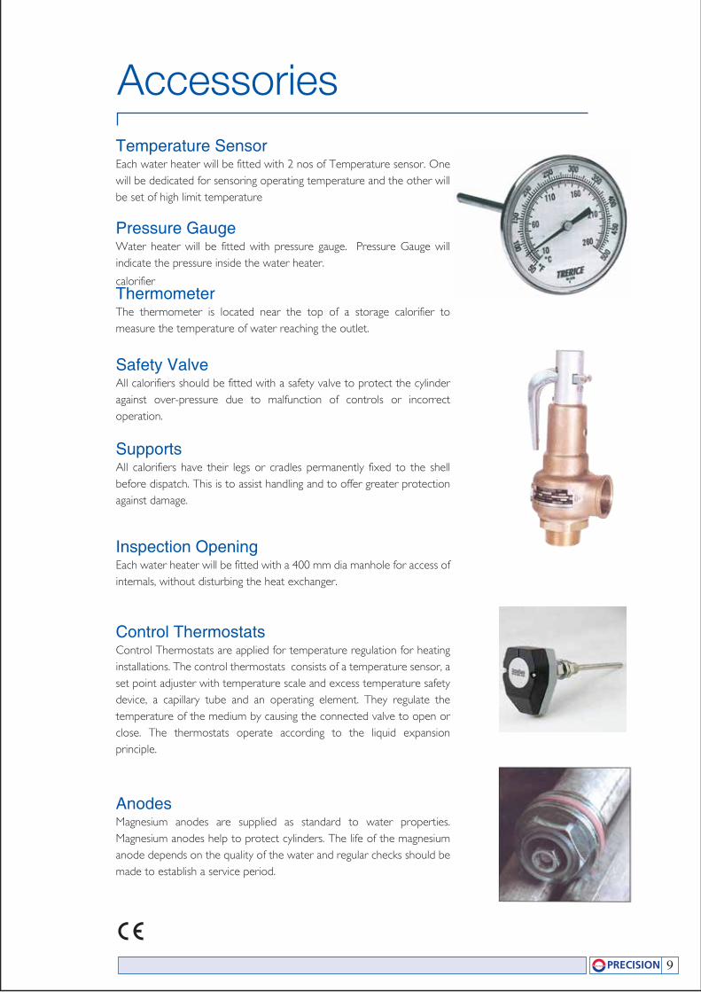
ThermometerThe thermometer is located near the top of a storage calorifier to measure the temperature of water reaching the outlet.
Pressure GaugeWater heater will be fitted with pressure gauge. Pressure Gauge will indicate the pressure inside the water heater.
Temperature SensorEach water heater will be fitted with 2 nos of Temperature sensor. One will be dedicated for sensoring operating temperature and the other will be set of high limit temperature
Safety ValveAll calorifiers should be fitted with a safety valve to protect the cylinder against over-pressure due to malfunction of controls or incorrect operation.
calorifier
SupportsAll calorifiers have their legs or cradles permanently fixed to the shell before dispatch. This is to assist handling and to offer greater protection against damage.
Inspection OpeningEach water heater will be fitted with a 400 mm dia manhole for access of internals, without disturbing the heat exchanger.
Control ThermostatsControl Thermostats are applied for temperature regulation for heating installations. The control thermostats consists of a temperature sensor, a set point adjuster with temperature scale and excess temperature safety device, a capillary tube and an operating element. They regulate the temperature of the medium by causing the connected valve to open or close. The thermostats operate according to the liquid expansion principle.
AnodesMagnesium anodes are supplied as standard to water properties. Magnesium anodes help to protect cylinders. The life of the magnesium anode depends on the quality of the water and regular checks should be made to establish a service period.
Accessories
9
Water Quality
InsulationAdequate thermal insulation is essential to prevent unnecessary heat losses from storage calorifiers
which may be standing for many hours at working temperature. Standard factory-fitted insulation
consists of 50mm thick Fiber glass wool mattress which is closely fitted to the shell and encased in mild
steel sheets of 1mm thick G.I sheets with one coat of redoxide primer and two coats of gloss paint.
Low Water Level SwitchLow water cut off probe type is fitted as standard for all water heaters.The risk of switching on the
heaters when they are not covered by water damages the electric heating element.
High Limit Cut OutAll fired water heaters is fitted with a high temperature cut out as standard. This acts as and immediate
monitor of overheating. It will be fitted with a manual reset button so that the heater will continue to
operate from the high limit switch if the control thermostat is malfunctioning.
All water contain dissolved substances A large proportion of these dissolved substances are generally calcium and magnesium carbonates and sulphates. The concentration of these salts in the water define the hardness of the water. Greater their concentration harder the water, smaller their concentration softer the water.
Generally, water which can be considered as slightly hard to moderately hard we must consider the effects on the immersion heaters and other components within the calorifier shell.
For more details please consult your water treatment SPECIALIST.
10
Useful Conversions
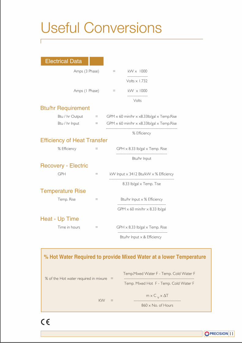
Amps (3 Phase) = kW x 1000 ---------------- Volts x 1.732
Amps (1 Phase) = kW x 1000 ---------------- Volts
Btu/hr RequirementBtu / hr Output = GPM x 60 min/hr x x8.33lb/gal x Temp.Rise
Btu / hr Input = GPM x 60 min/hr x x8.33lb/gal x Temp.Rise -------------------------------------------------------- % Efficiency
Efficiency of Heat Transfer% Efficiency = GPH x 8.33 lb/gal x Temp. Rise ---------------------------------------- Btu/hr Input
Recovery - ElectricGPH = kW Input x 3412 Btu/kW x % Efficiency --------------------------------------------------- 8.33 lb/gal x Temp. Tise
Temperature RiseTemp. Rise = Btu/hr Input x % Efficiency -------------------------------------- GPM x 60 min/hr x 8.33 lb/gal
Heat - Up TimeTime in hours = GPH x 8.33 lb/gal x Temp. Rise --------------------------------------- Btu/hr Input x & Efficiency
Electrical Data
% Hot Water Required to provide Mixed Water at a lower Temperature
Temp.Mixed Water F - Temp. Cold Water F % of the Hot water required in mixure = ------------------------------------------------------- Temp. Mixed Hot F - Temp. Cold Water F
m x C v x ∆T KW = ------------------------------------- 860 x No. of Hours
11
HEAT EXCHANGER PACKAGE
AIR RECEIVER
STEAM ACCUMULATORS
INDIRECT HEATED STORAGE CALORIFIERS
FEED TANKS & CONDENSATE RECEIVERS
BLOWDOWN VESSEL
ELECTRIC WATER HEATERS
BUFFER VESSELS
RANGE OF PRODUCTS
email: [email protected]
Precision Storage Vessels Pvt. Ltd.Kalpadi, P.O.
Kalpadi, K. K. Dist.Tamil Nadu, India
Tel : 0091 4651 237730Fax: 0091 4651 238585
www.precisionstoragevessels.com
Precision Storage Tanks LLP3rd Floor 82 King Street
Manchester MZYWQUnited Kingdom
Tel : 0044 161 8 325 080Fax: 0044 161 8 352 323
EN ISO 9001: 2000