Embed Size (px)
Citation preview

Processing Wellman
EcoLon Nylons

2
Contents
1. Material Handling
- Nylon Characteristics……………….….………….…………... 5
- Absorption of Moisture.……….……….………………………8
- Drying……………………………………….………………… 9
2. Injection Molding Machine
- Machine Recommendations………….……………………….13
- Barrel Temperature Profiles………….………..……………...16
- Measuring Melt Temperature……….…………..…………… 17
- Molding Conditions…….………………………..………….. 18
- Trouble Shooting Guide…………….…………….…………. 22
- Purging and Shut Down………………….………….………. 25
3. Molds - Mold Temperature………….…………………………….….. 27
- Gates……………….………………………………………… 28
- Runners…………………………………………………….… 30
- Venting………………………………………………………. 31
- Mold Shrinkage……………………………………………… 32
4. Parts Handling - Dimensional Stability………………………………………... 34
- Post Molding Environments……………………………….… 37
- Regrind………………………………………………………. 38

3
Preface
This guide is included to give basic recommendations on the use of
Wellman EcoLon nylon resins in the injection-molding environment.
Wellman with its comprehensive resources is ready to share its
accumulated knowledge with their customers. This guide will identify
the fundamental areas of the injection molding environment. We hope
it will be useful in obtaining optimum results when using Wellman
EcoLon nylons.
Because of the fallibility of all the elements involved, we are strong
proponents of prototype usage before committing to production design.
All recommendations are based on good faith effort to assist in your
application, they are, however, only recommendations. Therefore, the
information in this document is provided "as is" without warranty of
any kind, either expressed or implied, for fitness of use.
WELLMAN
Engineering Resins Division
520 Kingsburg Highway
Johnsonville, SC. 29555
1-800-821-6022
Revised on July 29, 2014

4
Base resin overview………………………………. 5
Absorption of moisture…………………………… 8
Drying……………………………………………. 9

5
BASE RESINS OVERVIEW
Nylon is a member of the thermoplastic polyamide (PA) family, and is considered to be
the first crystalline plastic. It was invented way back in the 1930's but introduced for
injection molding around 1943.
Largest selling commercial types:
NYLON 66
Derived from hexamethylene diamine and adipic acid.
Melt point of 260°C (500°F).
The generic formula is:
H2N (CH2) 6 NH2 + HOOC (CH2) 4 COOH =
H (HN(CH2)6 NHCO(CH2)4CO) OH + H2O
NYLON 6
Derived from caprolactam.
Melt point of 220°C (430°F).
The generic formula is:
CH2
/ \
CH2 C0 + H2 0
| |
CH2 NH
| | = H (NH(CH2 )5CO) OH
CH2 —— CH2
Nylons are among the toughest of all thermoplastics with excellent chemical, abrasion
and creep resistance. This, together with high tensile strength, rigidity and heat distortion
temperatures, makes nylon a very popular, cost effective, engineering resin.
All nylon compositions have certain molding advantages:
- Fast overall cycle times.
- Good weld strength.
- Good flow characteristics and toughness in thin sections.

6
BASE RESINS OVERVIEW
AMORPHOUS VS CRYSTALLINE
Most all of today's thermoplastics can be lumped into these two categories. There are,
however, very distinct differences between the two as follows:
CRYSTALLINE polymers have a very dense "ordered" structure, in which the molecules
in certain regions get tightly aligned. As heat is added, they remain solid until they reach
their sharp melting point, then all crystalline structure is destroyed and they become a
very easy flowing liquid like substance. Crystalline polymers include; nylon, PBT, PET,
polypropylene and polyethylene.
AMORPHOUS polymers don't really melt. Instead, they have a broad softening range.
The molecular structure is more like random coils or "spaghetti like." Very stiff flowing
at low temperatures, but as heat is increased, space is added between the molecules
making it more easily flowing. Amorphous polymers include; ABS, acrylics, styrene and
polycarbonates.
Figure 1.1

7
BASE RESINS OVERVIEW
CRYSTALLINITY
The morphological structure of both nylon 66 and nylon 6 is actually semicrystalline. If
you were to observe both through a microscope, two separate and distinct phases would
be revealed: an ordered crystalline phase and a random amorphous phase. This could
appear like crystalline islands surrounded by an amorphous sea (Figure 1.2).
Processing can greatly effect the level of crystallinity in molded parts because the more
slowly a melt of crystalline nylon is allowed to cool, the greater the degree of "as-
molded" crystallinity.
Figure 1.2 Crystallinity
Slower cooling promotes crystal formation.
Increased crystallinity means:
- Greater initial shrinkage
- Less chance for additional shrinkage
- Increased dimensional stability
- Better chemical resistance
- Increased heat deflection temperature (HDT)

8
HANDLING OF WELLMAN ECOLON NYLONS
Absorption of Moisture
Nylons exposed to the atmosphere for even short periods of time will
absorb moisture from the air and will become impossible to mold
successfully. As supplied, Wellman EcoLon nylons are dry and ready
for molding. To ensure that the material remains dry, these procedures
are recommended:
1) Do not allow nylon to be exposed to the atmosphere.
2) Before the nylon container is opened, allow the resin to reach
room temperature.
3) Wellman EcoLon nylons sold in bags can be resealed using a
heat-sealing iron.
4) If moisture level problems persist, the use of a dehumidifying
dryer should be considered. Dehumidifying dryers are discussed
later.
Moisture Absorption of EcoLon Pellets
hours
0.1
0.3
0.5
0.7
0.9
1.1
1.3
0 2 4 6 8 10 12 14
4 50% RH 75% RH 100% RH
moisture content %
73F exposure

9
Dryer Recommendations
Wellman EcoLon nylons are shipped dry and are ready for molding.
However, like many other engineering polymers, nylons have a great
affinity for water. Unless care is taken, the moisture level of nylons
will quickly rise and processing characteristics suffer. The use of
regrind can also introduce nylon of unknown moisture levels to the
nylon feedstock stream. For many processing facilities, the use of
dehumidifying hopper dryers has proven to be effective in the control of
nylon moisture levels.
Wellman recommends the use of dehumidifying desiccant bed hopper
dryers. Hot air dryers of any design are not recommended. Like other
engineering polymers, such as polyesters and polycarbonates, nylons
are hygroscopic. Hygroscopic materials absorb moisture from the
atmosphere. Non-hygroscopic materials such as polystyrene and
polypropylene require only surface moisture removal; hygroscopic
materials require removal of moisture from within the pellet. Because
of this difference, non-hygroscopic materials can use hot air dryers to
"blow off" moisture from the surface while dehumidifying dryers are
needed to dry hygroscopic materials in order to "wring out" moisture
from within.
Desiccant bed hopper dryers consist of a filter(s), a blower, a
dehumidifier or desiccant bed, a heater and a hopper. The drying
process consists of a cycle that begins when the desiccant bed traps
moisture from the air. This dry air is heated and blown to the hopper.
Moisture from the polymer is attracted to the dry air and is taken back
to the desiccant bed to begin the process again. Many dehumidifying
dryers possess at least two desiccant beds. One is being used to dry the
air while the other is being regenerated. This regeneration is the
removal of the moisture from the desiccant crystals to the atmosphere.
This enables the dehumidifying dryer to be used continuously.
10
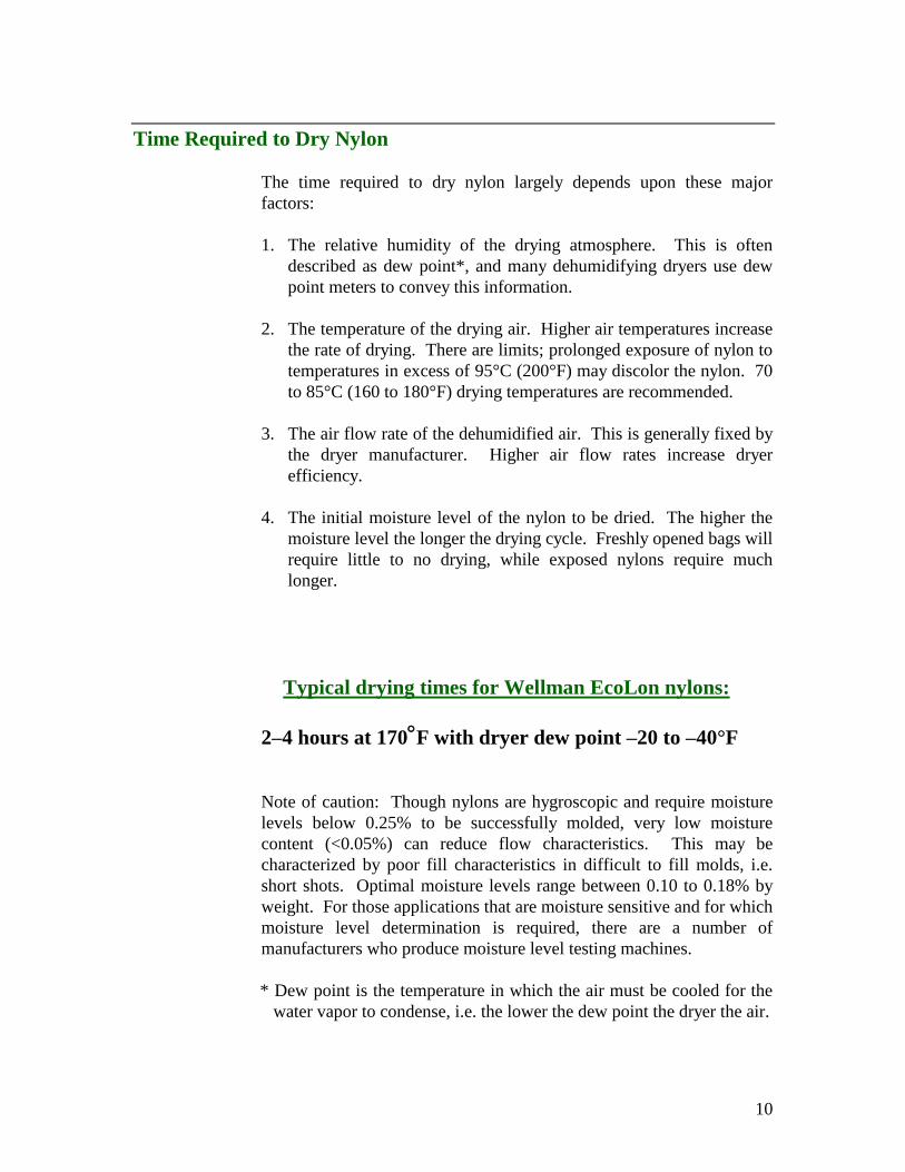
Time Required to Dry Nylon
The time required to dry nylon largely depends upon these major
factors:
1. The relative humidity of the drying atmosphere. This is often
described as dew point*, and many dehumidifying dryers use dew
point meters to convey this information.
2. The temperature of the drying air. Higher air temperatures increase
the rate of drying. There are limits; prolonged exposure of nylon to
temperatures in excess of 95°C (200°F) may discolor the nylon. 70
to 85°C (160 to 180°F) drying temperatures are recommended.
3. The air flow rate of the dehumidified air. This is generally fixed by
the dryer manufacturer. Higher air flow rates increase dryer
efficiency.
4. The initial moisture level of the nylon to be dried. The higher the
moisture level the longer the drying cycle. Freshly opened bags will
require little to no drying, while exposed nylons require much
longer.
Typical drying times for Wellman EcoLon nylons:
2–4 hours at 170F with dryer dew point –20 to –40°F
Note of caution: Though nylons are hygroscopic and require moisture
levels below 0.25% to be successfully molded, very low moisture
content (<0.05%) can reduce flow characteristics. This may be
characterized by poor fill characteristics in difficult to fill molds, i.e. short shots. Optimal moisture levels range between 0.10 to 0.18% by
weight. For those applications that are moisture sensitive and for which
moisture level determination is required, there are a number of
manufacturers who produce moisture level testing machines.
* Dew point is the temperature in which the air must be cooled for the
water vapor to condense, i.e. the lower the dew point the dryer the air.

11
Dryer Maintenance
The successful drying of nylon depends upon the working order of the
dryer. Improperly maintained dryers will quickly lose their ability to
remove moisture from nylon. Taken to the extreme, malfunctioning
dryers have proven to be effective in adding moisture to nylon. A
simple preventative maintenance program will be effective in keeping
drying equipment in good working order.
Filters - Improperly maintained filters are the primary cause of dryer
failure. Dirty filters can lead to desiccant beds that are contaminated
with fines, dust or dirt, and will severely inhibit the desiccant bed from
attracting moisture. Dirty filters will also slow the drying process by
reducing dry air through-put. Filters should be checked daily and will
generally require servicing on a weekly basis.
Desiccant Beds - Due to the constant wetting and drying process, the
desiccant bed will gradually lose their ability to absorb moisture.
Desiccant beds do not last forever and will eventually require
replacement. How long depends on the number of machine hours and
its freedom from fines, dirt, etc. Two years of service life is the typical
limit.

12
Machine recommendations……………….……. 13
Barrel temperature profiles…………………….. 16
Measuring melt temperature…………………… 17
Molding conditions……………………………. 18
Trouble shooting guide………………………… 22
Purging and shut down………………………… 25

13
INJECTION MOLDING MACHINE
Wellman EcoLon nylons are specifically designed for use in screw
type injection molding machines. This section is devoted to identifying
key injection molding machine characteristics that are important to the
successful molding of Wellman EcoLon nylons.
Shot Size Capacity
Shot size is the volume of material (by weight) that a given machine
will deliver in a single shot. Since polymers differ in density machine
manufacturers publish shot size capacity in terms of polystyrene. If a
machine's rated polystyrene shot size capacity is known it is possible to
accurately estimate the shot weight of any other polymer by relating
their respective densities. In the case of nylon, polystyrene has a near
equal melt density. Hence, the maximum shot size of unfilled nylons is
approximately equal to the shot size capacity given in polystyrene. The
table listed below gives details for filled nylons, which are higher in
density than polystyrene.
Material type % Greater than polystyrene
13% Glass Fill 10
33% Glass Fill 25
43% Glass Fill 35
40% Mineral Fill 35
Clamp Capacity
Clamp capacity is the amount of pressure available to hold a mold
closed while polymer that is being injected under pressure is trying to
force it open.
For Wellman EcoLon nylons it has been found that the clamp capacity
of an injection-molding machine should provide 3 to 5 tons of clamping
force for every square inch of projected shot area. High injection
pressures may dictate the higher clamping recommendation.
* Projected shot area is defined as the area of part(s) and runner(s) that
is present on the parting line of the tool.

14
Screw Design
Wellman recommends the use of screws designed for nylons. Most
molding applications require high through-put rates for which these
screws are specifically designed. In certain instances where through-
put rates are not critical general purpose screws that have been supplied
by the machine manufacturer can be used successfully. Listed below
are recommendations for high output screws when using Wellman
EcoLon nylons.
Screw size - minimum 20:1 length/diameter ratio
Compression ratio - 2.5:1 to 3.5:1
Metering depth - 0.070 - 0.100 in.
Feed Section - 30 to 40% of screw length
Transition section - 30 to 40% of screw length
Metering section - 30 to 40% of screw length

15
Nozzle Reverse taper nozzles (some suppliers call them nylon tip nozzles) are
used with greater success than ordinary general purpose tip nozzles.
The major feature of a reverse taper nozzle is the taper bore, which in
effect extends the sprue into the heated nozzle. The design feature will
allow lower nozzle temperatures and help to combat nozzle drool,
nozzle freeze and sprue sticking.
Non-Return Valve
Non-return valves are extremely important in the delivery of consistent
shot sizes. Worn and leaking valves will be characterized by the
inability to hold a cushion, inconsistent shot size and by allowing
polymer back flow, polymer degradation. The common sliding ring
check valve that provides streamlined flow is preferred. Running glass-
filled Wellman EcoLon nylons will require the use of hardened steel
and, depending on throughput, will provide a useful life of 4-6 months.
Cold slug may
develop
Preferred,
“reverse
taper”

16
MACHINE OPERATING CONDITIONS
Barrel Temperature Profile
To optimize molding performance, it will require matching cylinder
temperature profile to material requirements, machine requirements and
tool requirements. For example, in high throughput conditions, barrel
temperature profiles may require "hot" settings to allow sufficient heat
to be conducted to the polymer. Conversely, low though-put conditions
may require "cool" temperature settings to prevent nylon degradation.
It is important to note that small changes in temperature will not yield a
"perfect" heat profile. Nylons are quite forgiving and a good heat
profile will provide good processing characteristics.
Wellman recommends the use of a "reverse heat profile." Higher heats
in the rear zone followed by lower heats forward. Reverse heat profiles
generate consistent melt temperatures. For glass fiber reinforced nylon
the reverse heat profile will reduce breakage to the glass fiber and
reduce wear on the screw and barrel as if conveys the material forward.
The reverse heat profile (Temperature in Celsius).
Material type Barrel temp. Melt temp.
Front Center Rear
66 unfilled 265 270 275 265-275
66 filled 270-280 280-295 295-310 280-295
6 unfilled 260 265 270 255-265
6 filled 265-270 270-280 275-280 270-285
The reverse heat profile (Temperature in Fahrenheit).
Material type Barrel temp. Melt temp.
Front Center Rear
66 unfilled 510 520 530 510-530
66 filled 520-540 540-560 560-590 540-560
6 unfilled 500 510 520 490-510
6 filled 510-530 520-540 530-550 520-550
Screw injection machines melt nylon in two ways. Convection heat,
the heat produced by the barrel temperature, and shear heat, the
frictional heat generated by the rotating screw. Shear heat is difficult to
control, barrel heat is not.

17
Melt Temperature
In establishing proper operating conditions one of the most important
considerations is the melt temperature. Incorrect melt temperatures
may produce parts with unmelted particles of nylon being injected
when molded and may also contribute to poor surface finish,
pronounced weld lines, flash, black specking and a host of other
maladies. Actual melt temperatures are a function of screw design,
cycle times, screw speed and barrel temperature settings. While barrel
temperature can give a good indication of melt temperature, it can also
mislead what is thought to be melt temperature. Barrel temperature
readings only indicate what the temperature is of a thermal couple,
which is embedded in steel somewhere near a heater band. They do not
necessarily tell you what the actual plastic melt temperature is.
Measuring plastic melt temperature
It is possible to get accurate plastic temperature readings by using a
hand held pyrometer and inserting the probe into a melt pool or air shot.
The following guidelines may be helpful in providing a more systematic
approach to obtaining more consistently accurate readings. Again, it is
strongly advised that good safety practices are in place when handling
molten nylon.
Procedure:
- Preheat the probe of the hand held pyrometer to 20°F over the
average of the barrel temperature settings.
- Purge the machine on cycle and catch a purged shot into a
container.
- Insert preheated probe into melt center and stir for 20 seconds
- and record peak temperature.

18
Molding Conditions
Material type Barrel temp.
(°F)
Melt temp.
(°F)
Front Center Rear
66 unfilled 510 520 530 510-530
66 filled 520-540 540-560 560-590 540-560
6 unfilled 500 510 520 490-510
6 filled 510-530 520-540 530-550 520-550
1. Use minimum back pressure (less than 100 psi).
2. Melt decompression should be minimum necessary to prevent
nozzle drool.
3. Shot size should use most of material in barrel. We recommend
using a minimum cushion to insure packing of the cavities.
4. Match screw speed to overall cycle time, nylon in barrel should be
in a fairly steady state of motion.
5. Injection pressure set at maximum, which just avoids flashing, hold
pressure packs the part.
6. Injection speed on maximum, fill times generally less than 4
seconds, hold time till part packing is complete.
* Nylon is a crystalline material that changes from liquid to solid
quickly. The amount of time available to fill the part is limited.
Nozzle Nozzle temperature has little impact on melt temperature, but has a
large impact on processing conditions. Improper nozzle temperatures
can cause sprue sticking, nozzle drool, splay and nozzle freeze. Correct
nozzle temperature is dictated by the design of the nozzle, temperature
of mold, overall cycle time and type of nylon being used.
Nozzle temperatures are mold and machine specific. In determining
nozzle temperature a good place to start is a temperature that is just low
enough to prevent nozzle drool. For type 66 nylons nozzle
temperatures of 265 to 295°C are common (510 to 560°F). Type 6
nylons have nozzle temperatures that will typically range from 255 to
280°C (490 to 540°F).

19
Mold Temperature
Recommended mold cavity temperatures for Wellman EcoLon nylons
are 80 to 105°C (175 to 225° F). Hot mold temperature can improve
surface finish with filled materials, and improve physical properties of
the part. It is important to differentiate the cavity temperature with that
of the cooling medium temperature, which can be inaccurate indicators
of cavity temperature. Tools with insufficient cooling capacity will
produce varying cavity temperatures.

20
Screw Speed
For a given injection molding machine, through-put is primarily
controlled by screw speed (RPM). Increasing screw speed increases the
amount of polymer "pumped" through. Screw speed can also affect
melt quality. A properly designed nylon type screw will provide a good
quality melt regardless of screw RPM. General purpose screws will
often display lower melt temperatures with increased screw speeds.
General purpose screws with their excessive metering section depths
may also pump unmelted pellets into the melt stream.
When the injection molding machine is producing parts, Wellman
recommends that the nylon in the barrel remain in a fairly steady state
of motion. Select a screw retraction speed that will take approximately
90% of the available time to charge the barrel with molten nylon.
Melt Decompression
The use of melt decompression or suck-back is an aid in combating
nozzle drool. After the screw has filled the barrel with polymer the
screw is pulled back to relieve the pressure placed on the nozzle.
Excessive melt decompression will induce air entrapment in the melt
and produce voids in the molded part.
Back Pressure Increasing back pressure will increase the amount of mixing and
frictional heat generated by the screw. This will also introduce the
difficult to control shear heating effect. Wellman recommends that no
back pressure be used. This is especially true with regards to glass fiber
filled Wellman EcoLon nylons. The use of back pressure will cause
glass fiber breakage and can reduce the physical properties of the
molded part.

21
Injection Pressure
Depending upon tool design, injection pressures for Wellman EcoLon
nylons range from 20 to 138 MPa (3,000 to 20,000 psi). Most injection
molding machines make use of two injection pressures, fill and hold
(may be referred as 1st and 2nd stage).
During the filling phase, the set 1st stage pressure is really a secondary
variable. It is only necessary to have enough pressure available to
achieve the desired injection rates or fill time.
Usually a high 1st stage pressure is utilized because it is normally
recommended to fill as fast as possible as far as possible (roughly 95 to
99% filled), then transfer to a lower 2nd stage pressure to pack the
cavity. Ideally, transfer should be by screw position or cavity pressure.
Screw forward time
Screw forward time is the overall time of injection before screw
retraction, i.e. fill time plus hold time. It is important to have pressure
applied to the cavity until gate freeze. If the gate has not frozen,
increased shrinkage, voids and sink marks may develop.
The ideal screw forward time can be determined by weighing a series of
parts (without runner) at different times (while maintaining a consistent
cycle time) until the part reaches maximum weight.
Cavity pressure readings taken near the gate can also be used to determine ideal
screw forward time. A sharp drop in pressure as injection time concludes may
indicate the gate has not been sealed properly and discharge has occurred.

22
Cure time Cure time (or cooling time) begins as soon as the cavity is filled and
includes the time necessary for gate freeze and time to cool the part to a
temperature in which the stiffness is suitable for proper ejection.
The lowest possible melt and mold temperatures that can be used
successfully will yield the shortest cure times and fastest cycles.
Estimating cycle time
A rough guide to estimate total cycle time for unfilled nylon (EcoLon
NY1992) is 30 seconds per 1/8-inch thickness. Nucleated resins and
filled resins can often be molded on much shorter cycle times.
Overall Cycle (Seconds)
Part Thickness (Inches)
EcoLon
GF1960-BK
(PA66 35%GF)
EcoLon
GF2015-BK
(PA66 15%GF)
1/32 7 – 9 9 - 11
1/16 11 – 13 13 - 15
1/8 15 – 20 20 - 25
1/4 30 – 40 35 - 45
1/2 60 – 75 75 - 90

23
Trouble Shooting Molding Problems
Flashing Burn Marks
- Decrease cavity pressure - Decrease injection speed
- Decrease injection speed - Decrease melt temp.
- Decrease melt temp. - Dry material
- Decrease screw speed - Improve venting
- Decrease hold pressure - Increase gate size
- Improve mold venting - Change gate location
- Check press platens
for parallelism Brittleness
- Increase clamp tonnage - Decrease melt temp.
- Dry wet material
Short Shots - Decrease mold temp.
- Increase feed - Decrease use of regrind
- Increase melt temp. - Check for contamination
- Increase injection pressure - Immerse parts in water
- Increase injection speed
- Increase mold temp. Warpage
- Equalize temp. of both
Splay Marks mold halves
- Dry material - Observe mold for part
- Check for contamination ejection uniformity
- Decrease melt temp. - Decrease mold temp.
- Decrease nozzle temp. - Increase mold temp.
- Decrease melt decompression - Differentiate mold temp's
- Decrease injection speed - Decrease melt temp.
- Increase cure time
Weld lines
- Increase mold temp. Cavity sticking
- Increase melt temp. - Increase cool time
- Improve venting at weld line - Decrease mold temp.
- Increase injection speed - Decrease melt temp.
- Add overflow well adjacent - Decrease cavity pressure
to the weld line
- Check for contamination Nozzle Freeze
- Change gate location - Use reverse taper tip
- Increase nozzle temp.
- Increase decompression
- Increase mold temp.

24
WARPAGE
Warpage is the result of non uniform shrinkage. Non-uniform shrinkage can be caused
by:
Wall thickness variations Thicker sections will cool slower then thin sections,
resulting in a higher crystalline content and higher
shrinkage.
Temperature differentials Warping can occur if the mold surfaces are at
different temperatures, or if one area of the part
cools at a different rate.

25
Orientation With glass fiber reinforced materials during fill, the fibers
will orientate in the direction of flow (like logs in a river)
creating less shrink in the flow direction.
Pressure distribution An even pressure distribution is required for a
balanced packing of the part. Variations in
pressure can result in un-even shrinkage, causing
warp. Gate size, gate location, processing and part
geometry determines how evenly the pressure is
distributed.

26
Purging Purging for different color or material type can be economically
accomplished using high density polyethylene, polypropylene,
polystyrene or the acrylic purging compounds that are available. When
changing to a glass fiber filled Wellman EcoLon nylon, no special
purge materials are required. Glass fiber filled materials are abrasive
enough to scour the screw and barrel and can quickly provide a
homogeneous color. Purging with acrylic purging compounds will
require that the nozzle be removed. It is strongly advised that good
safety practices are in place when purging.
Shut Down Shut down should include emptying the hopper and vacating the screw
and barrel of nylon. Once accomplished, purging with a small amount
of polyethylene or polypropylene will reduce contamination and black
specks on subsequent runs.

27
Mold temperature…………….………………… 27
Gates…………………………………………… 28
Runners……………………….………………… 30
Venting……………………….………………… 31
Mold shrinkage…………………………….…… 32

28
MOLDS Wellman EcoLon nylons will generally provide excellent service in
molds that have been designed for semi-crystalline polymers.
However, there are specific points of design that should be considered.
Mold Temperature Controllers
High mold temperatures are recommended 80 to 105°C (175 to 225°F)
to prevent premature resin freezing. In general the hotter the mold the
better the surface finish of part and the physical properties of the part in
service.
Cooling Capacity
In mold cooling design the axiom to remember is to keep all part
contacting areas as close to the same temperature as possible.
Localized hot spots will cause differing shrink rates, which will invite
warpage, high stress levels, and parts out of dimensional tolerance.
In multicavity molds, cooling requirements are that the cooling medium
must flow parallel through the cavities rather than in series. Sufficient
cooling flow rates are required to keep outgoing temperatures within 10
degrees Fahrenheit of incoming temperatures.

29
Gates
Gates are designed to act as flow monitors and as flow switches. The
dimensions of the gate control how much polymer flows through and
controls how long the gate stays open by freezing off when flow stops.
Gates are of many designs. A rectangular gate is recommended. By
changing the thickness of a rectangular gate it is possible to change gate
freeze off time. Conversely changing the width of the gate will control
the amount of polymer that will flow for a given amount of time.
Round gates lose the independent control on freeze off and flow rate.
A change in dimension in a round gate will change both freeze and flow
rates.
In addition to round and rectangular gates, there are others:
Gate type Application
1) Fan Uniform filling of thin parts
2) Flash Rapid fill and freeze times
3) Pin point Simple degating
4) Sub gated pin point Automatic degating
Gate Sizing
Gate sizing is a balance of part design, mold design, polymer flow
characteristics and aesthetics.
Material suppliers ask for large gate sizing to assure a minimum
amount of shear heat at the gate and to maximize part packing. Part
producers ask for smaller gates for quick cycle times and pleasing
appearance. Often, the proper gate size is a compromise of the two.
Wellman recommends these general guidelines for gate dimensions.
Rectangular Gate thickness = 60% of part wall thickness.
Gate width = 1 to 2 times gate thickness.
Round Gate diameter = 50% of wall thickness.

30

31
Runner Design
Part producers want runner size to be as small as possible to keep
rework to a minimum and provide a maximum number of parts per
pound processed. Material suppliers are concerned with runners that
are sufficiently sized to provide minimum pressure and heat losses,
adequate part packing, and uniform filling of a multicavity mold.
Depending upon part performance criteria, these two philosophies
ultimately reach a position where runner flow characteristics are
adequate for the application.
Round runners are preferred in that they provide a minimum of surface
area which gives the lowest pressure and heat losses.

32
Venting In general, venting locations are a function of part and mold design.
Most molds will require that venting take place at the weld line and/or
at a point that is farthest from the gate. Vents for cavities and runners
are recessed areas usually 0.100" to 0.250" wide and 0.0005" to 0.002"
deep. These vents flow out to the exterior of the mold.
Wellman EcoLon nylons are semi-crystalline polymers that turn from
a liquid molten state to a solid state in a short period of time. To
successfully fill a cavity, fast fill times are used. If adequate venting is
not available, the resulting entrapment of air may manifest to these
problem conditions:
-Weld lines.
-Burning of the nylon.
-Cavity corrosion, charring or pitting.
-Shot size variations.
Table 2.6A VENT DIMENSIONS ( IN. )
Depth ( D1 ) Land ( L )
Wellman EcoLon Unfilled nylon 0.0005" - 0.001" 0.030" - 0.060"
Wellman EcoLon Mineral /Glass Reinforced 0.001" - 0.002" 0.030"

33
Mold Shrinkage
Mold Shrinkage is the expected difference in dimensions between
cavity steel and fully cooled parts. All plastics experience volume
reduction as they cool. Crystallization causes additional volume
reduction, which means more shrinkage.
Mold shrinkage is usually expressed as in./in., but can sometimes be
expressed as a percentage or in mils/in. In other words;
0.005" in./in. shrinkage = 0.5% shrinkage = 5 mils/in. shrinkage.
The shrinkage of parts molded from EcoLon resins is characteristic of
each grade and dependent on the thickness and geometry of the molded
part, molding conditions, and post molding conditions such as
annealing and moisture conditioning.
Typical shrinkage values obtained with various wall thicknesses for an
unfilled nylon are as follows:
Wall Thickness, in. Mold Shrinkage, in./in.
0.060 0.008 - 0.015
0.125 0.010 - 0.020
0.250 0.015 - 0.025
0.500 0.025 - 0.040
Processing conditions can have a significant effect on mold shrinkage.
The following adjustments decrease mold shrinkage, making the
molded part larger:
1. Reduce wall thickness
2. Increase injection pressure
3. Increase injection forward time
4. Increase gate size
5. Lower mold temperature
6. Lower material temperature
7. Increase injection speed
8. Increase cycle time

34
Dimensional stability…………...……………….. 34
Post molding environments………………..……. 37
Regrind………………………………………….. 38

35
DIMENSIONAL STABILITY OF WELLMAN WELLAMID NYLONS
Wellman EcoLon nylons are used with success in many applications
where dimensional stability is critical. All successes are the result of
careful prototype environmental testing and cannot be forecast by
simple calculations. Nylons do absorb moisture and they do change in
dimensions, but the dimensional change is often small and it is
predictable. Therefore the key to understanding dimensional stability is
to understand the variables that will affect dimensions.
Two forces act upon nylons after molding. The first is the absorption
of moisture which will cause the volume of the nylon to grow and the
second is stress relief; the relaxation of the nylon at a molecular level,
which will cause the resin to shrink. The two forces act in opposite
directions and tend to cancel each other out resulting in part dimensions
that are very close to "dry as molded" dimensions. In controlled
environments, the two forces are quite apparent. Freshly molded
samples shrink during stress relief, then when exposed to an ambient
environment grow with the absorption of moisture.
Absorption of Moisture
The amount of moisture absorption is dependent upon the environment
that the part will be exposed to. Constantly varying humidity levels
that are experienced in most environments produce no true equilibrium
moisture level. However, this does not present a dimensional problem
in that conditioned nylons absorb and give up moisture very slowly.
For all practical purposes, unless the part is in an extreme environment
(water submersion or heated oven, etc.), typical humidity levels fall
between 50 to 70% and produce moisture levels of 2.5 to 3.0%. Figure
4 is an illustration of the amount of moisture content achieved under
constant humidity environments. The dimensional change in nylon as a
function of moisture content is illustrated in Figure 5.
Examining the dimensional change of unfilled 66 nylon from the dry as
molded condition to total saturation, (8.5% water by weight), nearly
80% of the entire dimensional change occurs between 70% RH (4.3%
water) and 100% RH (8.5% water). 50% RH produces 11% of the total
change, and 60% RH produces 13%, only very high humidity levels
produce significant nylon growth.

36
Figure 4
Figure 5
Moisture Content vs. Relative Humidity
relative humidity
humidity
0 1 2 3 4 5 6 7 8 9
20% 40% 60% 80% 100%
NY1992-Unfilled GF 1960-35%GF)
moisture content %
Dimensional Change by Stress relief/Moisture absorption
relative humidity
humidity
-0.01
-0.005
0
0.005
0.01
0.015
0.02
0 20% 40% 60% 80% 100%
-NY1992
change from dry as molded in./in.

37
Stress Relief The second variable in dimensional stability is stress relief and
relaxation of the nylon, the final orientation of the nylon at a molecular
level. This variable is the most difficult to predict and is part specific.
An equation of stress relief derived from one part will not accurately
predict stress relief of another part design. In today's more
sophisticated moldings, large dimensional changes may occur in a most
critical dimension or may produce no change in the dimensionally
critical area while all movement is taking place elsewhere in the part.
This phenomenon may stem from gate location, molding parameters,
flow patterns and varying wall thickness or part handling after molding.
Time The time in which nylon becomes fully equilibrated to its working
environment (stress relief completed and moisture absorbed) is
dependent upon part thickness and part design. Equilibration of thin
moldings will produce dimensionally stable parts in a day or two while
thicker molding will take many days. Regardless of the amount of total
change, the change will continue to a specific point then stop. The
amount of stress relief is fixed and the change due to a specific
moisture level is fixed. Figure 6 will provide general guidelines for the
time involved for moisture absorption.
Figure 6

38
Post Molding Environments Part toughness is influenced by the moisture level of the nylon.
Wellman EcoLon nylons, like many other engineering polymers are
hygroscopic. Hygroscopic polymers absorb moisture from the air. To
successfully mold Wellman EcoLon nylon, the nylon must be dried to
low moisture levels (0.25% or below). Once molded the nylon will
slowly pick up moisture from the atmosphere to a level that is
consistent with the moisture level of the air, usually 2.5% moisture.
Parts of low moisture levels will exhibit poorer toughness
characteristics. Conversely, parts that have had a chance to absorb
moisture from the air will exhibit better toughness characteristics.
The time involved for moisture absorption and better toughness
characteristics to result is dependent upon the relative humidity of the
environment and the thickness of the part. Thin moldings can show
improved toughness in a day or two while thicker moldings will take
longer. If the time for moisture absorption is not available, providing
the nylon an easier access to moisture (part immersion, part boiling)
will shorten the time required for moisture absorption.
Figure 7
Immersion Time for 2% Moisture EcoLon NY1992
part thichness
0
5
10
15
20
25
30
0.05
5
0.10 0.15 0.20 0.25
time (hours)
water immersion at 73F

39
Regrind
Good quality regrind can be successfully used when mixed with
identical grades of Wellman EcoLon nylon. Regrind levels of up to
25% have been successfully used without significant loss of physical
properties.
Figure 8 is a graph that characterizes the effects of using a 25% regrind
/ 75% EcoLon ratios. This mixture was molded and tested for
physicals. Surplus molding from the 1st cycle were then ground up and
mixed at 25% with virgin. This was repeated four times to emulate
what would be done in practice with 25% regrind levels.
Figure 8
Effect of using 25% regrind EcoLon mineral/glass filled nylon
8
10
12
14
16
18
20
Virgin 1st cycle
cycle
2nd cycle 3rd cycle 4th cycle
Izod Impact Flex Modulus Tensile
normalized values