Embed Size (px)
Citation preview
NutriFit
Product description

ContactPriva
Zijlweg 3
2678 LC
P.O. Box 18
2678 ZG
De Lier
The Netherlands
T +31 174 522 600
F +31 174 522 700
www.priva.nl
3789674Article number:01.005Version:July 2012Date:
© Copyright 2012, Priva B.V. All rights reserved.
No part of this publication may be reproduced, published or stored in a retrieval system withoutwritten prior permission of Priva B.V.
This publication has been developed with care. However, the products shown may differ indimensions and design from the actual products. Priva B.V. will not accept any responsibility fordamages caused by any errors or deficiencies in this publication. Priva B.V. may modify its productsand the associated manuals without prior notice. Priva B.V. advises to check product, installation,hardware and if present software on irregularities.
Priva B.V. owns the patents, patent applications, trade marks or other intellectual property rightsregarding the products described in this publication. With this publication Priva B.V. does notgrant the use of the aforementioned intellectual property rights. Product and company names inthis publication may not be used without the permission of Priva B.V.
Terms of delivery are applicable to the products described in this publication. The most recentversion of these terms can be found on the web site of Priva B.V. (www.priva.nl)

NutriFit
1NutriFit
ContentsAbout this product description ............................................................................................................... 4
Availability ...................................................................................................................................................................................................... 4
Documentation ............................................................................................................................................................................................. 4
Explanation of symbols in this document ............................................................................................................................................ 4
Introduction ................................................................................................................................................... 5
Accurate dosing ............................................................................................................................................................................................ 5
Compact design ............................................................................................................................................................................................ 5
Computer-operated ...................................................................................................................................................................................... 6
Efficient, safe and reliable ....................................................................................................................................................................... 6
For each irrigation system ......................................................................................................................................................................... 6
Optimal mixing ............................................................................................................................................................................................. 7
Environmentally friendly ............................................................................................................................................................................ 7
Pumps for each situation ........................................................................................................................................................................... 7
Capacity ........................................................................................................................................................................................................... 8
System overview .......................................................................................................................................... 9
Operating principle .................................................................................................................................. 12
Construction ............................................................................................................................................... 14
Technical specifications - general ......................................................................................................................................................... 16
Technical specifications - mechanical ................................................................................................................................................. 16
Technical specifications - electrical ...................................................................................................................................................... 18
Location and environmental conditions ............................................................................................................................................ 19
Capabilities ................................................................................................................................................. 20
Applications ................................................................................................................................................................................................. 20
Basic functions ........................................................................................................................................................................................... 20
Models .......................................................................................................................................................... 21
Technical specifications - process computer ..................................................................................................................................... 22
Dosing channels ....................................................................................................................................... 24
Technical specifications - dosing channels ........................................................................................................................................ 24
System pumps ............................................................................................................................................ 25
Calculating the irrigation capacity ...................................................................................................................................................... 25
Pump characteristics ................................................................................................................................................................................. 26
EC sensors ................................................................................................................................................... 30
2NutriFit
pH sensors .................................................................................................................................................. 31
Flow sensor (litre counter) ..................................................................................................................... 32
Supply water quality ................................................................................................................................ 33
Supply water pressure and capacity ................................................................................................... 35
Filters ............................................................................................................................................................ 36
Fertiliser supply ......................................................................................................................................... 38
Maintenance .............................................................................................................................................. 39
Warranty and safety ................................................................................................................................ 40
EC Declaration of Conformity .............................................................................................................. 41
3NutriFit
About this product descriptionThis product description relates to the NutriFit, a compact and affordable fertiliser dosing unit.The principle, structure and operation of the dosing unit are discussed here. Use this productdescription to select the configuration of the fertiliser dosing unit. This product description alsodeals with the preconditions for installation and use of the NutriFit
AvailabilityThis document is available in the following formats:• as a paper document;• as a PDF document on Dealernet AGRO of Priva: www.priva.nl.
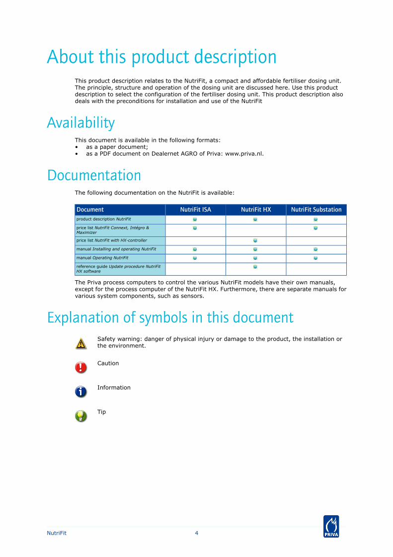
DocumentationThe following documentation on the NutriFit is available:
NutriFit SubstationNutriFit HXNutriFit ISADocumentproduct description NutriFit
price list NutriFit Connext, Intégro &Maximizer
price list NutriFit with HX-controller
manual Installing and operating NutriFit
manual Operating NutriFit
reference guide Update procedure NutriFitHX software
The Priva process computers to control the various NutriFit models have their own manuals,except for the process computer of the NutriFit HX. Furthermore, there are separate manuals forvarious system components, such as sensors.
Explanation of symbols in this documentSafety warning: danger of physical injury or damage to the product, the installation orthe environment.
Caution
Information
Tip
4NutriFit
Introduction
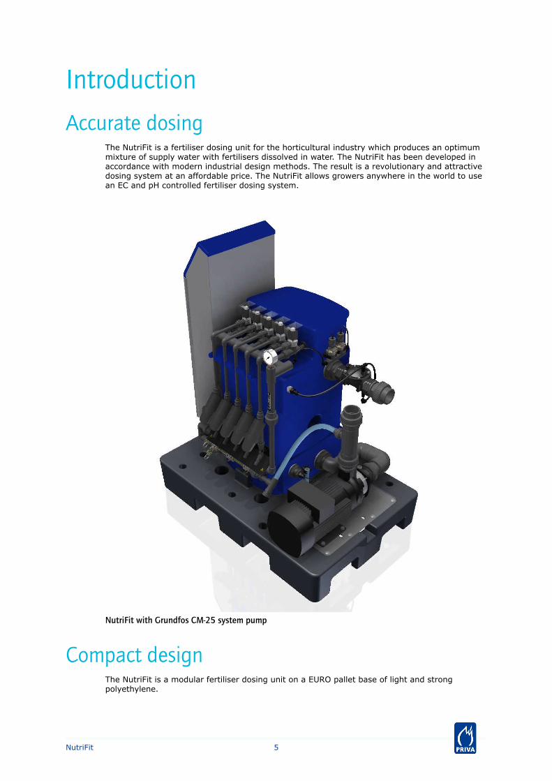
Accurate dosingThe NutriFit is a fertiliser dosing unit for the horticultural industry which produces an optimummixture of supply water with fertilisers dissolved in water. The NutriFit has been developed inaccordance with modern industrial design methods. The result is a revolutionary and attractivedosing system at an affordable price. The NutriFit allows growers anywhere in the world to usean EC and pH controlled fertiliser dosing system.
NutriFit with Grundfos CM-25 system pump
Compact designThe NutriFit is a modular fertiliser dosing unit on a EURO pallet base of light and strongpolyethylene.
5NutriFit
The NutriFit is modest in its dimensions, being 124 x 85 x 142 cm (LxWxH excluding packaging)and is lightweight, being 90 .. 200 kg depending on the system pump and controller.
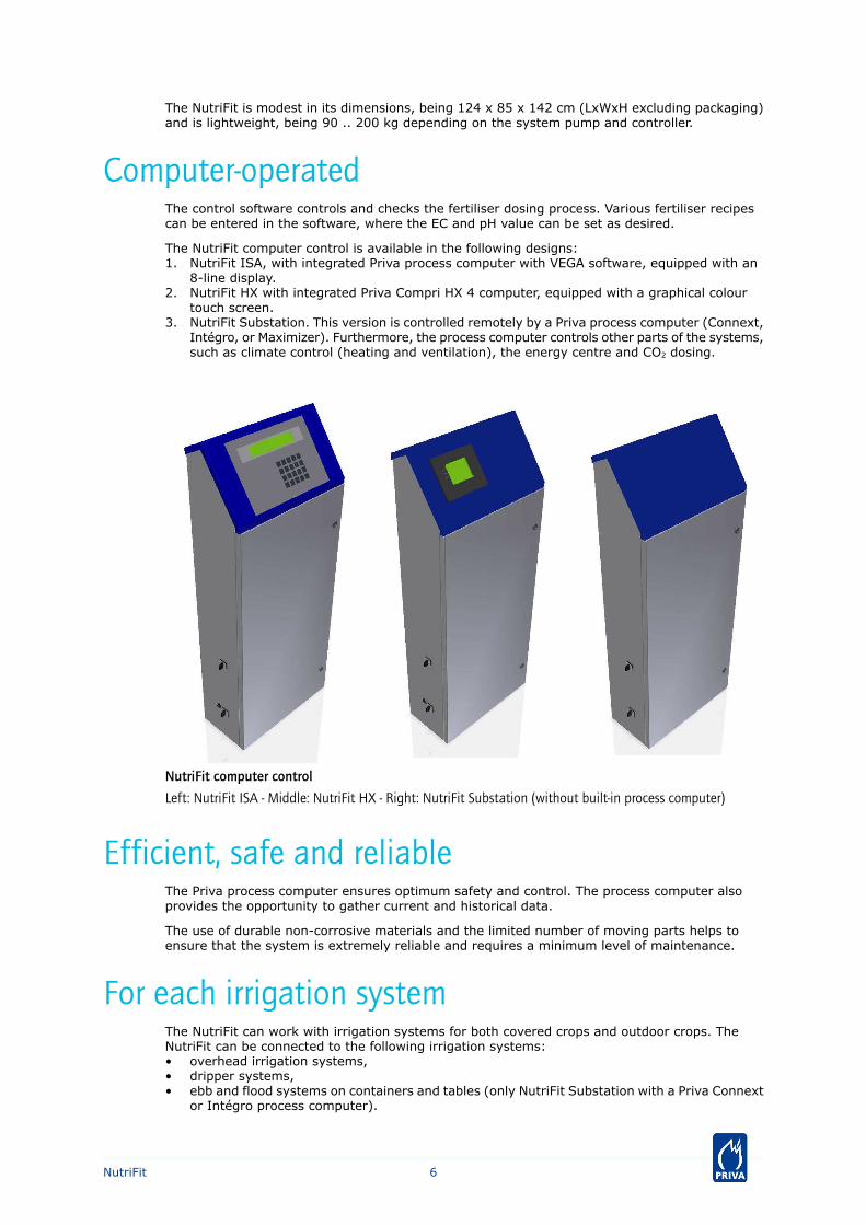
Computer-operatedThe control software controls and checks the fertiliser dosing process. Various fertiliser recipescan be entered in the software, where the EC and pH value can be set as desired.
The NutriFit computer control is available in the following designs:1. NutriFit ISA, with integrated Priva process computer with VEGA software, equipped with an
8-line display.2. NutriFit HX with integrated Priva Compri HX 4 computer, equipped with a graphical colour
touch screen.3. NutriFit Substation. This version is controlled remotely by a Priva process computer (Connext,
Intégro, or Maximizer). Furthermore, the process computer controls other parts of the systems,such as climate control (heating and ventilation), the energy centre and CO2 dosing.
NutriFit computer control
Left: NutriFit ISA - Middle: NutriFit HX - Right: NutriFit Substation (without built-in process computer)
Efficient, safe and reliableThe Priva process computer ensures optimum safety and control. The process computer alsoprovides the opportunity to gather current and historical data.
The use of durable non-corrosive materials and the limited number of moving parts helps toensure that the system is extremely reliable and requires a minimum level of maintenance.
For each irrigation systemThe NutriFit can work with irrigation systems for both covered crops and outdoor crops. TheNutriFit can be connected to the following irrigation systems:• overhead irrigation systems,• dripper systems,• ebb and flood systems on containers and tables (only NutriFit Substation with a Priva Connext
or Intégro process computer).
6NutriFit
Optimal mixingThe NutriFit has a maximum of 5 dosing channels with which a maximum of 5 fertiliser solutionsor 4 fertiliser solutions and 1 acid or lye solution can be dosed simultaneously. The dosing channelshave been constructed so that they are able to dose the required solution with a high degree ofaccuracy. The dissolved fertilisers and the acid or lye are optimally mixed with the supply waterin the compact mixing tank (net 80 l) thanks to the spray head. The result is stable, homogenousirrigation water with the desired mixing ratio for fertilisers. This water is pumped by the systempump to the crop through one or more irrigation lines and irrigation valves.
The NutriFit can be used for two fertiliser mixing principles:• The A+B principle where equal quantities of solutions A and B are dosed. This principle is
generally used for outdoor crop and substrate cultivation and for pot plants.• The ABC principle where various fertilisers (such as nitrogen, phosphates and potassium) are
dosed with adjustable ratios. This principle is often used at an international level for potplants.
A nominal dilution of 1:100 (fertiliser:water) in the fertiliser stock tanks is assumed for bothprinciples.
The NutriFit is provided with double EC and pH sensors to measure the conductivity (and by thatthe fertiliser concentration) and the acidity level of the irrigation water and to adjust it to thedesired EC and pH value. This ensures optimum conditions for the plants.
Environmentally friendlyTo avoid waste of valuable water and the dissolved fertilisers that it contains, the NutriFit HX andNutriFit Substation (only Connext/Intégro only) can mix drain water with clean supply water viaan EC pre-control valve. This makes an average saving of 30 .. 40 % on water and fertiliserspossible. At the same time, it avoids unnecessary pollution of the environment.
The EC pre-control valve, the related extra components, and the installation work mustbe added by the dealer or installer. Refer to System overview (page 9).
Pumps for each situationEvery NutriFit fertiliser dosing unit is fitted with a system pump. The unit is available with a rangeof different system pumps, depending on the water capacity, water pressure, mains voltage andmains supply. System pumps are available for a mains frequency of 50 and 60 Hz with different3-phase mains voltages with or without neutral. System pumps of 4 kW and higher are fitted witha soft starter.
Further refer to the pump characteristics and the price list.
7NutriFit
Capacity
Pump capacityThe fertiliser dosing unit is available with a net pumping capacity of approximately 5 to 20 m3/h,depending on the system pump used. In case of direct irrigation, this suffices for 0.5 to 2 ha.
Operating pressureUsually, the nominal operating pressure of the system pump is 2.5 to 4.0 bar. This pressure isnecessary, amongst others, to drive the venturi's in the dosing channels.
The maximum permissible pressure is 6.0 bar. In the event that a pump is installed withtoo high a capacity and pressure, there is a risk of leaks and damage to the fertiliserdosing unit. In addition, the electrical power consumption will be unnecessarily high.
Maximum dosing capacityThe maximum dosing capacity of the dosing channels is 300 l/h per channel at a minimum drivewater pressure of 2.0 bar on the venturi. The dosing capacity is almost independent of the drivewater pressure as long as it is 2.0 bar at minimum. A typical dose is 1 l fertiliser solution per100 l of irrigation water.
To obtain a higher dosing capacity for a particular fertiliser solution, it is, of coarse, possible toapply multiple dosing channels for this fertiliser solution. To connect multiple dosing valves to anoutput of the I/O board, solid state relays must be added.
Accuracy of the dosing channel at a low doseIf the dosing with a dosing channel is less than 10 % of the maximum dosing capacity, the dosingaccuracy will decrease. This is caused by the fact that the viscosity and specific mass of thefertiliser solutions, line resistance and fluid level in the fertiliser tanks plays a role at such lowflow rates. In such cases, the following solutions can be applied:• Dilute the fertiliser solution, for example so that it the dosing ratio will be 2 l of fertiliser
solution to 100 l of irrigation water (2:100 instead of the usual 1:100).• Let the engineer adjust the restriction screw of the dosing valve so as to reduce the maximum
capacity (a dosing channel doses accurately between 10 and 100 % of the maximum flowrate. By decreasing the maximum flow rate, the minimum flow rate is decreased as well).
Pump capacity and volume of drive water• A part of the capacity of the system pump is used to deliver drive water to the venturi's of
the dosing channels. Therefore the net capacity of the unit is less than the gross capacity ofthe system pump, depending on the number of venturi's.
• The drive water flow rate also depends on the system pump pressure. At a higher pressure,the flow rate is higher. A typical drive water flow rate is 510 l/h per venturi at a system pumppressure of 3.0 bar.
• In the net capacity curves (see Pump characteristics (page 26)), the capacity of the unit (=net pump flow rate) is shown versus the pump pressure, taking into account the drive waterconsumption of a typical number of venturi's.
Furthermore refer to Technical specifications - general (page 16) and Technical specifications -dosing channels (page 24).
8NutriFit
System overview
Scope of delivery
Graphic of the NutriFit
(The scope of delivery consists of the components within the grey section. The components shown with adashed line are optional. The figure, including the numbers outside the grey section, is explained further inthe chapter Operating principle (page 12)).
A NutriFit fertiliser dosing unit consists of the following components:
ComponentNo.1)
filling valve2
spray head3
mixing tank4
control float5
low level switch6
system pump7
drain point9
2 EC sensors10
dirt filter11
manometer12
2 pH sensor holders with pressure-resistant pH sensors13
a maximum of 5 dosing channels, each with a venturi (14), dosage valve (15), filter (16, optional) and rotameter (17,optional)
14, 15, 16and 17
control panel with process computer (NutriFit ISA and NutriFit HX) or without process computer (NutriFit Substation)20
1)Only the numbers that relate to the scope of delivery
9NutriFit
Required components outside the scope of delivery
Graphic of the environment of the NutriFit
In addition to the NutriFit, other components are required in order to implement an irrigationsystem. Which components these are depends on the configuration of the irrigation system.Typical components include the following:
ExplanationComponentNo.Water supply
If the supply water contains more than 1.25 mmol/l bicarbonate,it must be pre-treated with acid (see Supply water quality (page33)).
pre-treatment of supply water-
There can be multiple tanks or silos (1) with supply water, forinstance a tank for drain water and a tank for fresh water. Formaintenance or in the event of problems, make sure that thewater supply can be shut off with a manually operated valve (2).
silos or tanks with manually operated valve1 and 2
Prevent blockages by installing a dirt filter or filter in the supplywater line(s).
dirt filters or filters3
If water is used from more than one tank or silo, water must beprevented from flowing from one tank to another by means ofnon-return valves.
non-return valves in the supply water lines4
On account of the high EC value of drain water, this water canonly be reused as irrigation water by mixing it with fresh water(low EC value). The NutriFit HX and the NutriFit Substation (onlywith Connext or Intégro process computer) may control an ECpre-control valve for this purpose, based on an EC measurementof the mixed water. This EC pre-control ensures that the supplywater has a constant EC value.
EC pre-control or flow ratio control5
In a similar manner, a flow ratio control may also be implementedwith which water from different tanks is mixed in a specific ratio.
The capacity of the supply water must be at least equal to andpreferably slightly greater than the net capacity of the systempump. The pressure must be 2 - 4 bar. If the supply water doesnot intrinsically already have sufficient static pressure, a supplypump (6) is required. If the supply water intrinsically already hassufficient pressure, an electric supply valve (7) is required. Thesupply pump or supply valve may be controlled from the NutriFit.
supply pump and supply valve6, 7and 8
If the pressure is too high, a pressure reducing valve (8) mustbe installed in addition to the supply valve.
Supply of fertilisers and acid or lye
In the case of the A+B mixing principle, a NutriFit Substation(only with Connext or Intégro process computer) can control thedosings in such a way that the level in the fertiliser tanks fallsequally ('balance level control'). For this purpose, the fertilisertanks must be fitted with level sensors (9). See also Fertilisersupply (page 38)
stock tanks for fertilisers (10) and acid or lye (13)9, 10and 13
For maintenance or in the event of problems, make sure that thesupply of fertilisers and acid or lye can be shut off with a manuallyoperated valve, in any case on the side of the stock tank, butpreferably also on the side of the NutriFit.
manually operated valves11
10NutriFit
ExplanationComponentNo.Although the dosing channels of the NutriFit are already equippedwith a filter, it is advisable also to install a dirt filter or filter onthe side of the stock tank. Preferably install extra valves to enableflushing of the filter.
dirt filters or filters12
Distribution of irrigation water
The preparation of irrigation water and its distribution to the cropcan be started and stopped based on various criteria. One of thepossibilities is to influence the start time according to the intensityof the sunlight. A light sensor can be connected for this purpose.The NutriFit can also be (manually) started via an external startcontact.
light measurement and external start contact-
Ensure that a non-return valve is installed in the main irrigationline immediately after the dosing unit in order to prevent thereturn flow of irrigation water after the unit has stopped. Returnflow of irrigation water to the dosing unit may give rise toblockages or flooding as a result of the mixing tank overflowing.
non-return valve14
It is advisable to fit valves with which, during the adjustment ofthe NutriFit or in the event of problems, the irrigation water canbe drained to the sewer or to a discharge tank, instead of to thecrop.
valves to enable draining15 and17
Install a sand filter or screen filter to prevent blockages in thedistribution network. See also Filters (page 36).
filter16
The quantity of irrigation water to the crop can be controlled andmonitored with a paddle wheel flow sensor (‘litre counter’). Foreach valve section, a certain quantity can be measured out andthe dosing control can anticipate changes in the flow, so that thedesired quality of irrigation water is quickly available.
flow sensor18
The irrigation valves (electric diaphragm valves) can be controlledfrom the hardware of the NutriFit. Ensure that the flow in thevarious valve sections is as equal as possible and is in line withthe capacity of the system pump.
irrigation valves19
The NutriFit ISA and the NutriFit Substation (only with Connextor Intégro process computer) can control an electric rinse valveat the end of the main irrigation line to flush the line in the eventof a recipe change.
rinse valve20
11NutriFit
Operating principle
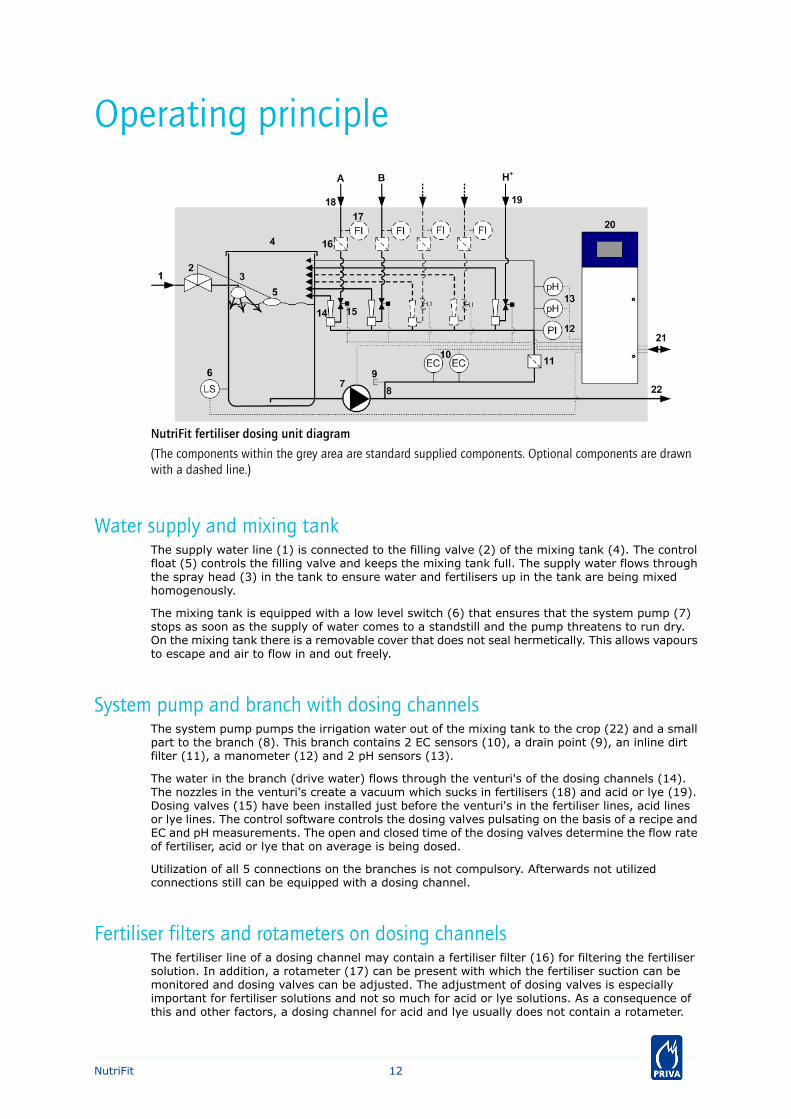
NutriFit fertiliser dosing unit diagram
(The components within the grey area are standard supplied components. Optional components are drawnwith a dashed line.)
Water supply and mixing tankThe supply water line (1) is connected to the filling valve (2) of the mixing tank (4). The controlfloat (5) controls the filling valve and keeps the mixing tank full. The supply water flows throughthe spray head (3) in the tank to ensure water and fertilisers up in the tank are being mixedhomogenously.
The mixing tank is equipped with a low level switch (6) that ensures that the system pump (7)stops as soon as the supply of water comes to a standstill and the pump threatens to run dry.On the mixing tank there is a removable cover that does not seal hermetically. This allows vapoursto escape and air to flow in and out freely.
System pump and branch with dosing channelsThe system pump pumps the irrigation water out of the mixing tank to the crop (22) and a smallpart to the branch (8). This branch contains 2 EC sensors (10), a drain point (9), an inline dirtfilter (11), a manometer (12) and 2 pH sensors (13).
The water in the branch (drive water) flows through the venturi's of the dosing channels (14).The nozzles in the venturi's create a vacuum which sucks in fertilisers (18) and acid or lye (19).Dosing valves (15) have been installed just before the venturi's in the fertiliser lines, acid linesor lye lines. The control software controls the dosing valves pulsating on the basis of a recipe andEC and pH measurements. The open and closed time of the dosing valves determine the flow rateof fertiliser, acid or lye that on average is being dosed.
Utilization of all 5 connections on the branches is not compulsory. Afterwards not utilizedconnections still can be equipped with a dosing channel.
Fertiliser filters and rotameters on dosing channelsThe fertiliser line of a dosing channel may contain a fertiliser filter (16) for filtering the fertilisersolution. In addition, a rotameter (17) can be present with which the fertiliser suction can bemonitored and dosing valves can be adjusted. The adjustment of dosing valves is especiallyimportant for fertiliser solutions and not so much for acid or lye solutions. As a consequence ofthis and other factors, a dosing channel for acid and lye usually does not contain a rotameter.
12NutriFit
Inline dirt filter and manometer on branchThe inline dirt filter (11) in the branch prevents the venturi nozzles of the dosing channels frombeing blocked. During maintenance or if the unit is taken out of operation for some time (in theevent of frost for example), the dosing channels can be emptied through the drain point (9).
A visual check of the drive water pressure (and thus the pump pressure) can be done by meansof the manometer (12) on the branch.
EC and pH sensorsThe electrical conductivity (measure of fertiliser concentration) of the irrigation water is measuredby means of EC sensors (10) on the branch. The pH sensors (13) measure the pH value of theirrigation water. The pH-sensors are in a sensor holder that is connected to the branch with athin line to prevent the pump pressure from interfering.
Using 2 EC sensors and 2 pH sensors, the control software can compare the measurements ofthe 2 sensors. If the measurements differ too much, the control software will indicate that oneof the sensors does not work (properly) and will stop the unit to prevent crop damage. Whileawaiting maintenance or sensor replacement carry on working with the other sensor is temporarilypossible. In that case, the user himself must keep an eye on the proper functioning of the remainingsensor (otherwise crop damage may still occur!)
CabinetThe process computer can be built-in inside the cabinet (20) or set up externally. In case of aremote process computer the unit is a substation. Then, the process computer communicateswith the electrical components in the cabinet through the (Connext or Intégro) network or bymeans of direct connections (Maximizer). Depending on the unit model, various other connections(21) can be present in the cabinet, for example connections for mains voltage, irrigation valves,a supply valve of supply pump, a flush valve and sensors.
13NutriFit
Construction
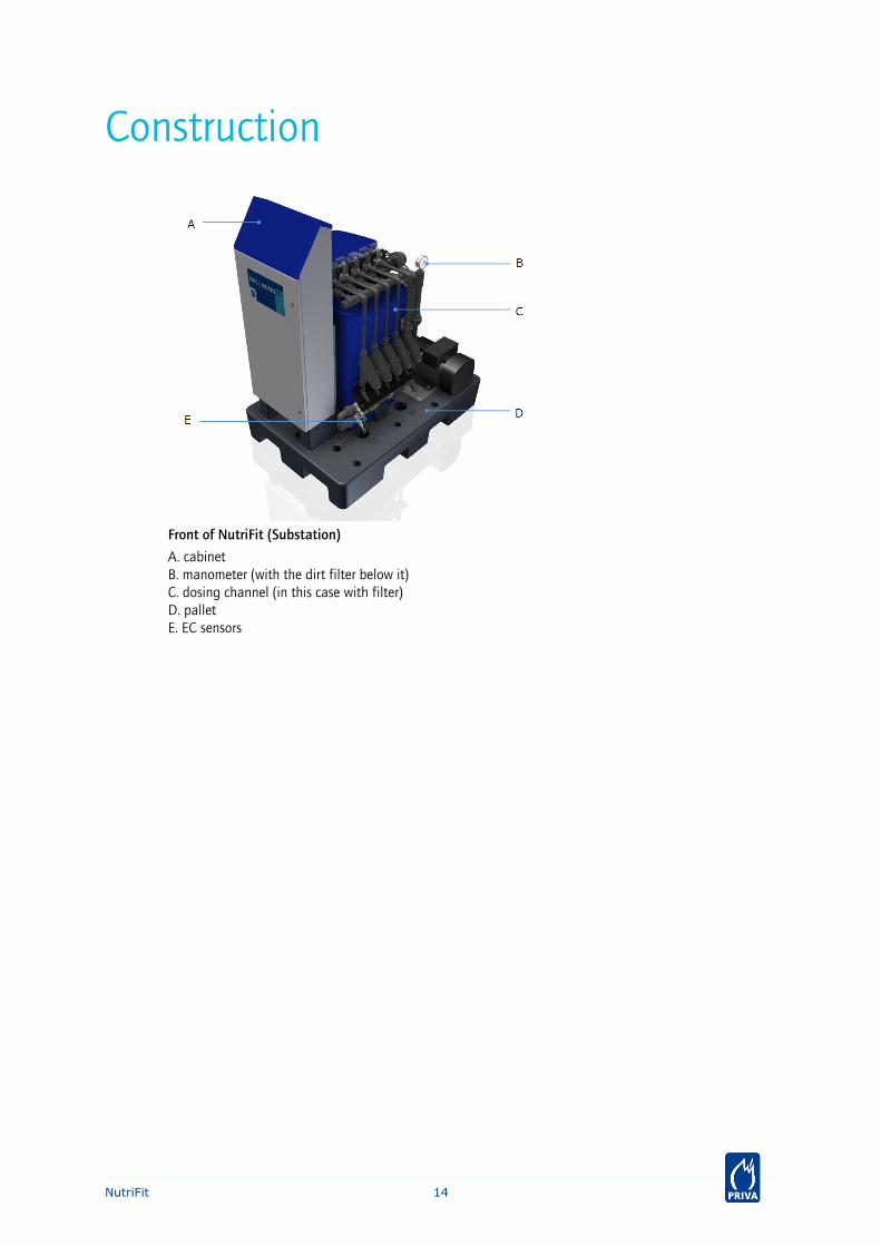
Front of NutriFit (Substation)
A. cabinetB. manometer (with the dirt filter below it)C. dosing channel (in this case with filter)D. palletE. EC sensors
14NutriFit
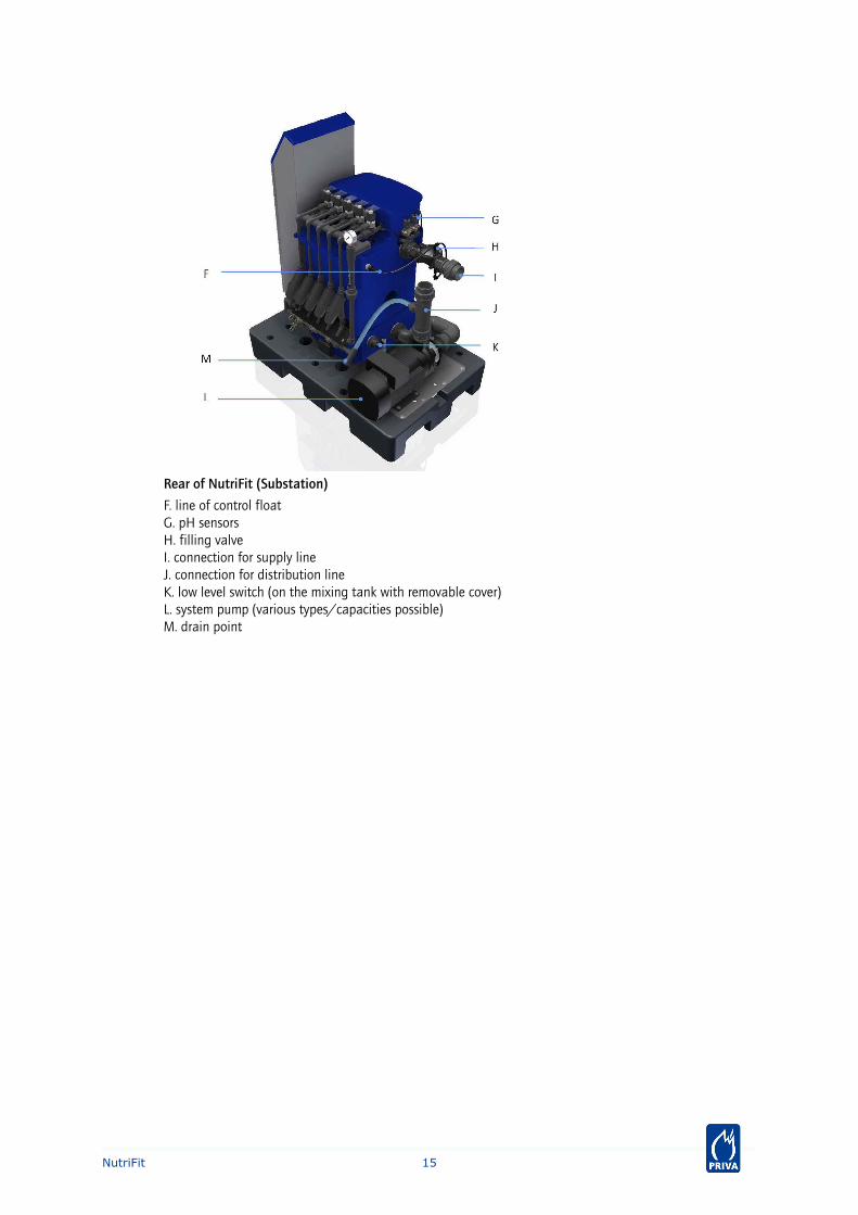
Rear of NutriFit (Substation)
F. line of control floatG. pH sensorsH. filling valveI. connection for supply lineJ. connection for distribution lineK. low level switch (on the mixing tank with removable cover)L. system pump (various types/capacities possible)M. drain point
15NutriFit
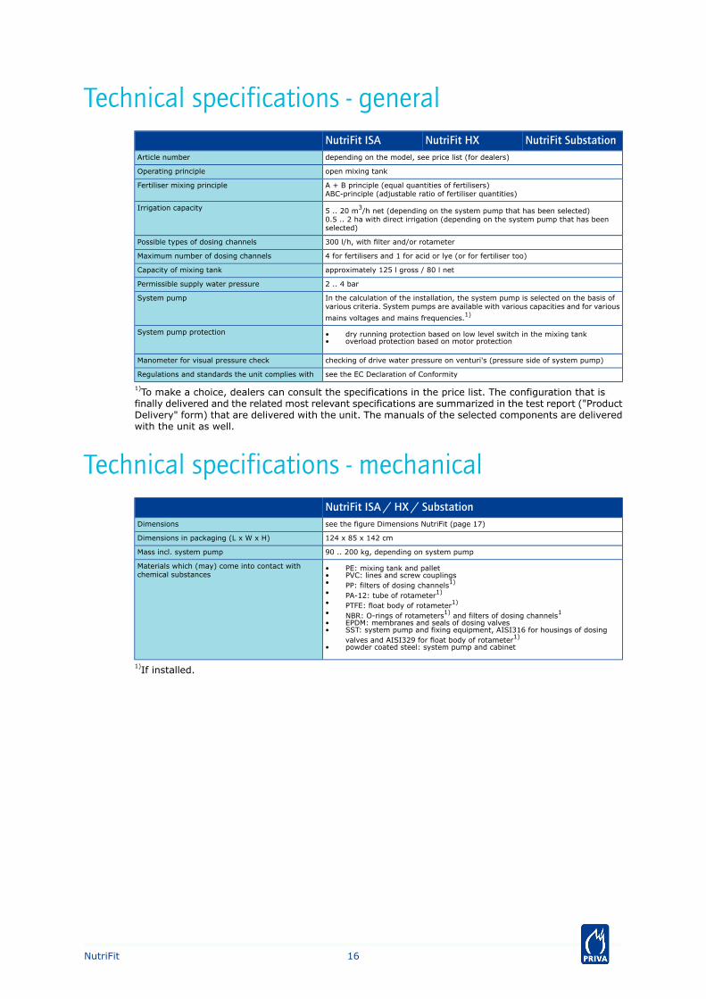
Technical specifications - generalNutriFit SubstationNutriFit HXNutriFit ISA
depending on the model, see price list (for dealers)Article number
open mixing tankOperating principle
A + B principle (equal quantities of fertilisers)ABC-principle (adjustable ratio of fertiliser quantities)
Fertiliser mixing principle
5 .. 20 m3/h net (depending on the system pump that has been selected)0.5 .. 2 ha with direct irrigation (depending on the system pump that has beenselected)
Irrigation capacity
300 l/h, with filter and/or rotameterPossible types of dosing channels
4 for fertilisers and 1 for acid or lye (or for fertiliser too)Maximum number of dosing channels
approximately 125 l gross / 80 l netCapacity of mixing tank
2 .. 4 barPermissible supply water pressure
In the calculation of the installation, the system pump is selected on the basis ofvarious criteria. System pumps are available with various capacities and for various
mains voltages and mains frequencies.1)
System pump
System pump protection • dry running protection based on low level switch in the mixing tank• overload protection based on motor protection
checking of drive water pressure on venturi's (pressure side of system pump)Manometer for visual pressure check
see the EC Declaration of ConformityRegulations and standards the unit complies with
1)To make a choice, dealers can consult the specifications in the price list. The configuration that isfinally delivered and the related most relevant specifications are summarized in the test report ("ProductDelivery" form) that are delivered with the unit. The manuals of the selected components are deliveredwith the unit as well.
Technical specifications - mechanicalNutriFit ISA / HX / Substationsee the figure Dimensions NutriFit (page 17)Dimensions
124 x 85 x 142 cmDimensions in packaging (L x W x H)
90 .. 200 kg, depending on system pumpMass incl. system pump
Materials which (may) come into contact withchemical substances
• PE: mixing tank and pallet• PVC: lines and screw couplings• PP: filters of dosing channels1)
• PA-12: tube of rotameter1)
• PTFE: float body of rotameter1)
• NBR: O-rings of rotameters1) and filters of dosing channels1
• EPDM: membranes and seals of dosing valves• SST: system pump and fixing equipment, AISI316 for housings of dosing
valves and AISI329 for float body of rotameter1)
• powder coated steel: system pump and cabinet
1)If installed.
16NutriFit
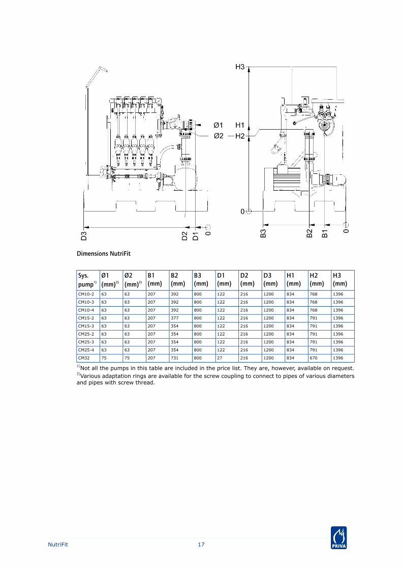
Dimensions NutriFit
H3(mm)
H2(mm)
H1(mm)
D3(mm)
D2(mm)
D1(mm)
B3(mm)
B2(mm)
B1(mm)
Ø2(mm)2)
Ø1(mm)2)
Sys.pump1)
139676883412002161228003922076363CM10-2
139676883412002161228003922076363CM10-3
139676883412002161228003922076363CM10-4
139679183412002161228003772076363CM15-2
139679183412002161228003542076363CM15-3
139679183412002161228003542076363CM25-2
139679183412002161228003542076363CM25-3
139679183412002161228003542076363CM25-4
13966708341200216278007312077575CM32
1)Not all the pumps in this table are included in the price list. They are, however, available on request.2)Various adaptation rings are available for the screw coupling to connect to pipes of various diametersand pipes with screw thread.
17NutriFit
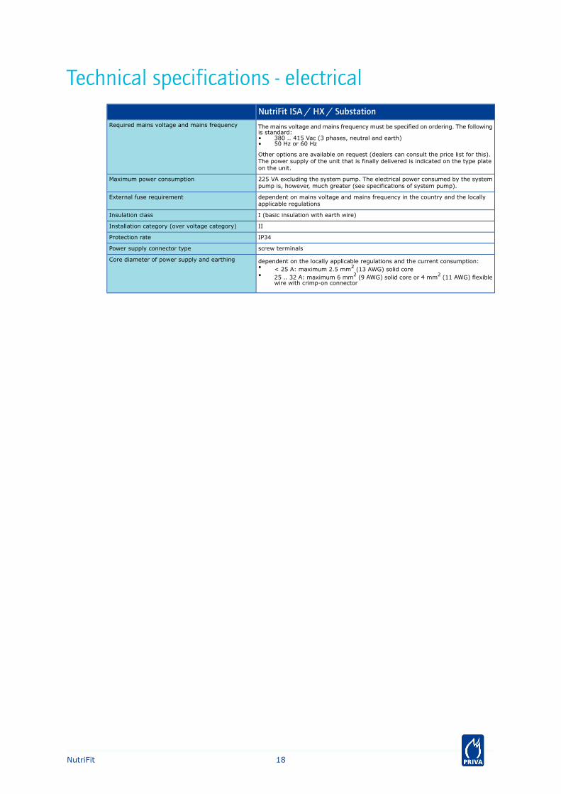
Technical specifications - electricalNutriFit ISA / HX / Substation
The mains voltage and mains frequency must be specified on ordering. The followingis standard:
Required mains voltage and mains frequency
• 380 .. 415 Vac (3 phases, neutral and earth)• 50 Hz or 60 Hz
Other options are available on request (dealers can consult the price list for this).The power supply of the unit that is finally delivered is indicated on the type plateon the unit.
225 VA excluding the system pump. The electrical power consumed by the systempump is, however, much greater (see specifications of system pump).
Maximum power consumption
dependent on mains voltage and mains frequency in the country and the locallyapplicable regulations
External fuse requirement
I (basic insulation with earth wire)Insulation class
IIInstallation category (over voltage category)
IP34Protection rate
screw terminalsPower supply connector type
dependent on the locally applicable regulations and the current consumption:Core diameter of power supply and earthing• < 25 A: maximum 2.5 mm2 (13 AWG) solid core• 25 .. 32 A: maximum 6 mm2 (9 AWG) solid core or 4 mm2 (11 AWG) flexible
wire with crimp-on connector
18NutriFit
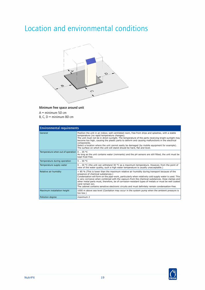
Location and environmental conditions
Minimum free space around unit
A = minimum 50 cmB, C, D = minimum 80 cm
Environmental requirementsPosition the unit in an indoor, well-ventilated room, free from drips and splashes, with a stabletemperature (no rapid temperature changes).The unit must not be in direct sunlight. The temperature of the parts receiving bright sunlight maybecome too high, causing the plastic parts to deform and causing malfunctions in the electricalcomponents.Select a location where the unit cannot easily be damaged (by mobile equipment for example).The surface on which the unit will stand should be hard, flat and level.
General
0 .. 35 °CAs long as the unit contains water (remnants) and the pH sensors are still fitted, the unit must bekept frost-free.
Temperature when out of operation
5 .. 30 °CTemperature during operation
5 .. 30 °C (the unit can withstand 30 °C as a maximum temperature. However, from the point ofview of the water quality, such a high water temperature is usually unacceptable.)
Temperature supply water
< 85 % (This is lower than the maximum relative air humidity during transport because of thepresence of chemical substances.)Condensation will form on the pipe-work, particularly when relatively cold supply water is used. Thisis very corrosive when combined with the vapours from the chemical substances. Hose clamps andother metal parts must, therefore, be of corrosion-resistant types of metals or must be well coated(and remain so).The cabinet contains sensitive electronic circuits and must definitely remain condensation-free.
Relative air humidity
1000 m above sea level (Cavitation may occur in the system pump when the ambient pressure istoo low.)
Maximum installation height
maximum 2Pollution degree
19NutriFit
Capabilities
ApplicationsThe most common application of the NutriFit is for directly dosing fertilisers: 'direct distribution'.In this respect, the NutriFit transports the irrigation water which contains dissolved fertilisers viathe irrigation lines and irrigation valves directly to the various crop areas. The NutriFit may beused for overhead irrigation systems, drippers and ebb and flood systems on containers andtables (only NutriFit Substation with a Priva Connext or Intégro process computer). Dependingon the crop, one NutriFit can supply irrigation water to areas of approximately 0.5 .. 2 ha. In thisapplication the NutriFit is only active during irrigation.
For larger areas a NutriFit can be used to fill one or more day storage tanks: 'indirect distribution'.The irrigation water from the day storage tanks is transported to the crop areas by separatepumps and valves. A NutriFit can make the nutrient solution(s) which are then stored in tanksas a buffer stock for a period of 24-hours. In this case, a NutriFit with a pump of lower capacity,which is typically active at night, will suffice.
For even larger areas or under critical cultivation conditions, it is recommended that the irrigationwater is prepared using 2 or more NutriFit fertiliser dosing systems. In the event of a breakdown,the user can switch over to the other NutriFit and thereby provide the plants with a minimumvolume of irrigation water to prevent damage to the crop.
Basic functionsThe construction of the NutriFit is suitable for a various functions when creating irrigation water:• dosing and mixing fertilisers and supply water into homogenous irrigation water;• correcting the pH and EC of the irrigation water;• pumping the irrigation water to the crop;• functioning as a 'break tank': because the mixing tank is open and the spray head on the
water inlet is installed above the water level, it is impossible that water is ever pushed intothe supply line. This is a requirement to be allowed to connect the water system directly tothe public water supply.
20NutriFit
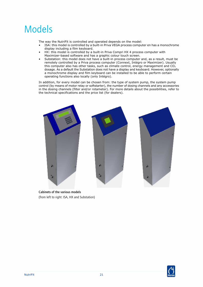
ModelsThe way the NutriFit is controlled and operated depends on the model:• ISA: this model is controlled by a built-in Priva VEGA process computer en has a monochrome
display including a film keyboard.• HX: this model is controlled by a built-in Priva Compri HX 4 process computer with
Maximizer-based software and has a graphic colour touch screen.• Substation: this model does not have a built-in process computer and, as a result, must be
remotely controlled by a Priva process computer (Connext, Intégro or Maximizer). Usuallythis computer also has other tasks, such as climate control, energy management and CO2
dosage. As a default the Substation does not have a display and keyboard. However, optionallya monochrome display and film keyboard can be installed to be able to perform certainoperating functions also locally (only Intégro).
In addition, for every model can be chosen from: the type of system pump, the system pumpcontrol (by means of motor relay or softstarter), the number of dosing channels and any accessoriesin the dosing channels (filter and/or rotameter). For more details about the possibilities, refer tothe technical specifications and the price list (for dealers).
Cabinets of the various models
(from left to right: ISA, HX and Substation)
21NutriFit
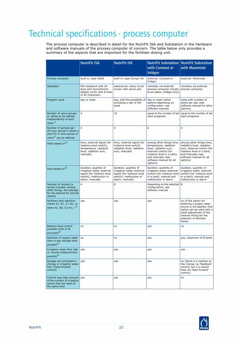
Technical specifications - process computerThe process computer is described in detail for the NutriFit ISA and Substation in the hardwareand software manuals of the process computer of concern. The table below only provides asummary of the aspects that are important for the fertiliser dosing unit.
NutriFit Substationwith Maximizer
NutriFit Substationwith Connext orIntégro
NutriFit HXNutriFit ISA
external: Maximizerexternal: Connext orIntégro
built-in, type Compri HXbuilt-in, type VEGAProcess computer
remotely via externalprocess computer
remotely via externalprocess computer (locallyas an option, Intégro only)
waterproof, colour touchscreen with stylus pen
film keyboard with 24keys and monochromedisplay (LCD) with 8 linesof 40 characters
Operation
week with number ofstarts per day (seesoftware manual for otheroptions)
day or week (otheroptions depending onconfiguration, seesoftware manual)
day, with the possibility ofexcluding a day of theweek
day or weekProgram cycle
equal to the number of setstart programs
equal to the number of setstart programs
104Number of valve groupsor valves to be startedindependently of each
other1)
4644Number of periods per24-hour period in which astart for a valve group or
valve1) can be defined
among other things time,radiation level, radiationsum, external control (forinstance level in a tank)and manually (seesoftware manual for alloptions)
among other things time,temperature, radiationlevel, radiation sum,external control (forinstance level in a tank)and manually (seesoftware manual for alloptions)
time, external signal (forinstance level switch)radiation level, radiationsum, manually
time, external signal (forinstance level switch),temperature, radiationlevel, radiation sum,manually
Start based on2)
duration, quantity ofirrigation water, externalcontrol (for instance levelin a tank), manual andmalfunction or alarm
duration, quantity ofirrigation water, externalcontrol (for instance levelin a tank), manual andmalfunction or alarm
duration, quantity ofirrigation water, externalsignal (for instance levelswitch), malfunction oralarm, manually
duration, quantity ofirrigation water, externalsignal (for instance levelswitch), malfunction oralarm, manually
Stop based on2)
8depending on the selectedconfiguration, seesoftware manual
84Number of recipes (arecipe includes, amongother things, the settingsfor the desired EC and pHvalues)
no (if the option forselecting a supply watersource is not applied, thatoption can be used with asmall adjustment of theinternal wiring for theselection of fertilisertanks)
yesyesyesFertiliser tank selection(tanks A1, B1, C1 etc. or
tanks A2, B2, C2 etc.) 2)
noyesnonoBalance level controlpossible (with A+B
principle)2)
yes, maximum of 8 tanksyesnonoSelection of supply watersilos or day storage silos
possible2)
yesyesyesyesIrrigation water flow rateor volume measurement
possible2)
no (there is a reaction tothe change via 'feedback'control, but it is slowerthan via 'feed forward'control)
yesyesyesDosage can anticipate achange in irrigation waterflow ('feed forward'control)
noyesyesyesControl may take accountof the number of irrigationvalves that are open atthe same time
22NutriFit
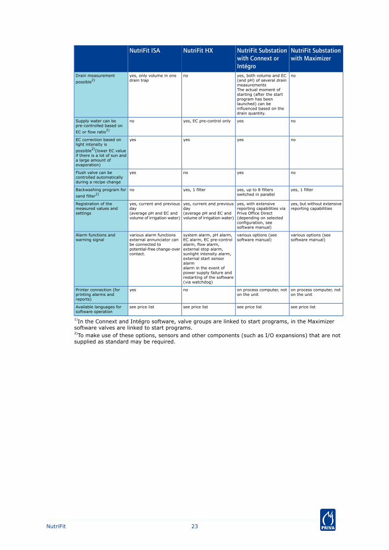
NutriFit Substationwith Maximizer
NutriFit Substationwith Connext orIntégro
NutriFit HXNutriFit ISA
noyes, both volume and EC(and pH) of several drainmeasurements
noyes, only volume in onedrain trap
Drain measurement
possible2)
The actual moment ofstarting (after the startprogram has beenlaunched) can beinfluenced based on thedrain quantity.
noyesyes, EC pre-control onlynoSupply water can bepre-controlled based on
EC or flow ratio2)
noyesyesyesEC correction based onlight intensity is
possible2)(lower EC valueif there is a lot of sun anda large amount ofevaporation)
noyesnoyesFlush valve can becontrolled automaticallyduring a recipe change
yes, 1 filteryes, up to 8 filtersswitched in parallel
yes, 1 filternoBackwashing program for
sand filter2)
yes, but without extensivereporting capabilities
yes, with extensivereporting capabilities viaPriva Office Direct(depending on selectedconfiguration, seesoftware manual)
yes, current and previousday(average pH and EC andvolume of irrigation water)
yes, current and previousday(average pH and EC andvolume of irrigation water)
Registration of themeasured values andsettings
various options (seesoftware manual)
various options (seesoftware manual)
system alarm, pH alarm,EC alarm, EC pre-controlalarm, flow alarm,external stop alarm,sunlight intensity alarm,external start sensoralarm
various alarm functionsexternal annunciator canbe connected topotential-free change-overcontact.
Alarm functions andwarning signal
alarm in the event ofpower supply failure andrestarting of the software(via watchdog)
on process computer, noton the unit
on process computer, noton the unit
noyesPrinter connection (forprinting alarms andreports)
see price listsee price listsee price listsee price listAvailable languages forsoftware operation
1)In the Connext and Intégro software, valve groups are linked to start programs, in the Maximizersoftware valves are linked to start programs.2)To make use of these options, sensors and other components (such as I/O expansions) that are notsupplied as standard may be required.
23NutriFit
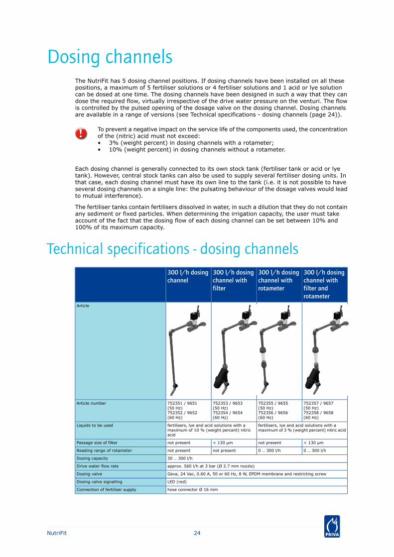
Dosing channelsThe NutriFit has 5 dosing channel positions. If dosing channels have been installed on all thesepositions, a maximum of 5 fertiliser solutions or 4 fertiliser solutions and 1 acid or lye solutioncan be dosed at one time. The dosing channels have been designed in such a way that they candose the required flow, virtually irrespective of the drive water pressure on the venturi. The flowis controlled by the pulsed opening of the dosage valve on the dosing channel. Dosing channelsare available in a range of versions (see Technical specifications - dosing channels (page 24)).
To prevent a negative impact on the service life of the components used, the concentrationof the (nitric) acid must not exceed:• 3% (weight percent) in dosing channels with a rotameter;• 10% (weight percent) in dosing channels without a rotameter.
Each dosing channel is generally connected to its own stock tank (fertiliser tank or acid or lyetank). However, central stock tanks can also be used to supply several fertiliser dosing units. Inthat case, each dosing channel must have its own line to the tank (i.e. it is not possible to haveseveral dosing channels on a single line: the pulsating behaviour of the dosage valves would leadto mutual interference).
The fertiliser tanks contain fertilisers dissolved in water, in such a dilution that they do not containany sediment or fixed particles. When determining the irrigation capacity, the user must takeaccount of the fact that the dosing flow of each dosing channel can be set between 10% and100% of its maximum capacity.
Technical specifications - dosing channels300 l/h dosingchannel withfilter androtameter
300 l/h dosingchannel withrotameter
300 l/h dosingchannel withfilter
300 l/h dosingchannel
Article
752357 / 9657(50 Hz)752358 / 9658(60 Hz)
752355 / 9655(50 Hz)752356 / 9656(60 Hz)
752353 / 9653(50 Hz)752354 / 9654(60 Hz)
752351 / 9651(50 Hz)752352 / 9652(60 Hz)
Article number
fertilisers, lye and acid solutions with amaximum of 3 % (weight percent) nitric acid
fertilisers, lye and acid solutions with amaximum of 10 % (weight percent) nitricacid
Liquids to be used
< 130 µmnot present< 130 µmnot presentPassage size of filter
0 .. 300 l/h0 .. 300 l/hnot presentnot presentReading range of rotameter
30 .. 300 l/hDosing capacity
approx. 560 l/h at 3 bar (Ø 2.7 mm nozzle)Drive water flow rate
Geva, 24 Vac, 0.60 A, 50 or 60 Hz, 8 W, EPDM membrane and restricting screwDosing valve
LED (red)Dosing valve signalling
hose connector Ø 16 mmConnection of fertiliser supply
24NutriFit
System pumps
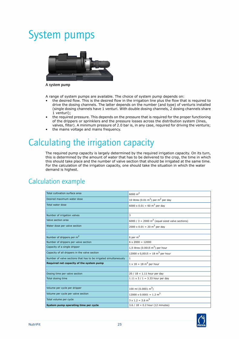
A system pump
A range of system pumps are available. The choice of system pump depends on:• the desired flow. This is the desired flow in the irrigation line plus the flow that is required to
drive the dosing channels. The latter depends on the number (and type) of venturis installed(single dosing channels have 1 venturi. With double dosing channels, 2 dosing channels share1 venturi);
• the required pressure. This depends on the pressure that is required for the proper functioningof the drippers or sprinklers and the pressure losses across the distribution system (lines,valves, filter). A minimum pressure of 2.0 bar is, in any case, required for driving the venturis;
• the mains voltage and mains frequency.
Calculating the irrigation capacityThe required pump capacity is largely determined by the required irrigation capacity. On its turn,this is determined by the amount of water that has to be delivered to the crop, the time in whichthis should take place and the number of valve section that should be irrigated at the same time.For the calculation of the irrigation capacity, one should take the situation in which the waterdemand is highest.
Calculation example
6000 m2Total cultivation surface area
10 litres (0.01 m3) per m2 per dayDesired maximum water dose
6000 x 0.01 = 60 m3 per dayTotal water dose
.
3Number of irrigation valves
6000 / 3 = 2000 m2 (equal sized valve sections)Valve section area
2000 x 0.01 = 20 m3 per dayWater dose per valve section
.
6 per m2Number of drippers per m2
6 x 2000 = 12000Number of drippers per valve section
1,5 litres (0.0015 m3) per hourCapacity of a single dripper
12000 x 0,0015 = 18 m3 per hourCapacity of all drippers in the valve section
1Number of valve sections that has to be irrigated simultaneously
1 x 18 = 18 m3 per hourRequired net capacity of the system pump
.
20 / 18 = 1.11 hour per dayDosing time per valve section
1.11 x 3 / 1 = 3.33 hour per dayTotal dosing time
.
100 ml (0.0001 m3)Volume per cycle per dripper
12000 x 0.0001 = 1.2 m3Volume per cycle per valve section
3 x 1.2 = 3.6 m3Total volume per cycle
3.6 / 18 = 0.2 hour (12 minutes)System pump operating time per cycle
25NutriFit
60 / 3.6 = 16.667Number of cycles per dayRound this to 17 cycles of 12 x 16.667 / 17 = 11.76 minutes (11minutes and 46 seconds)
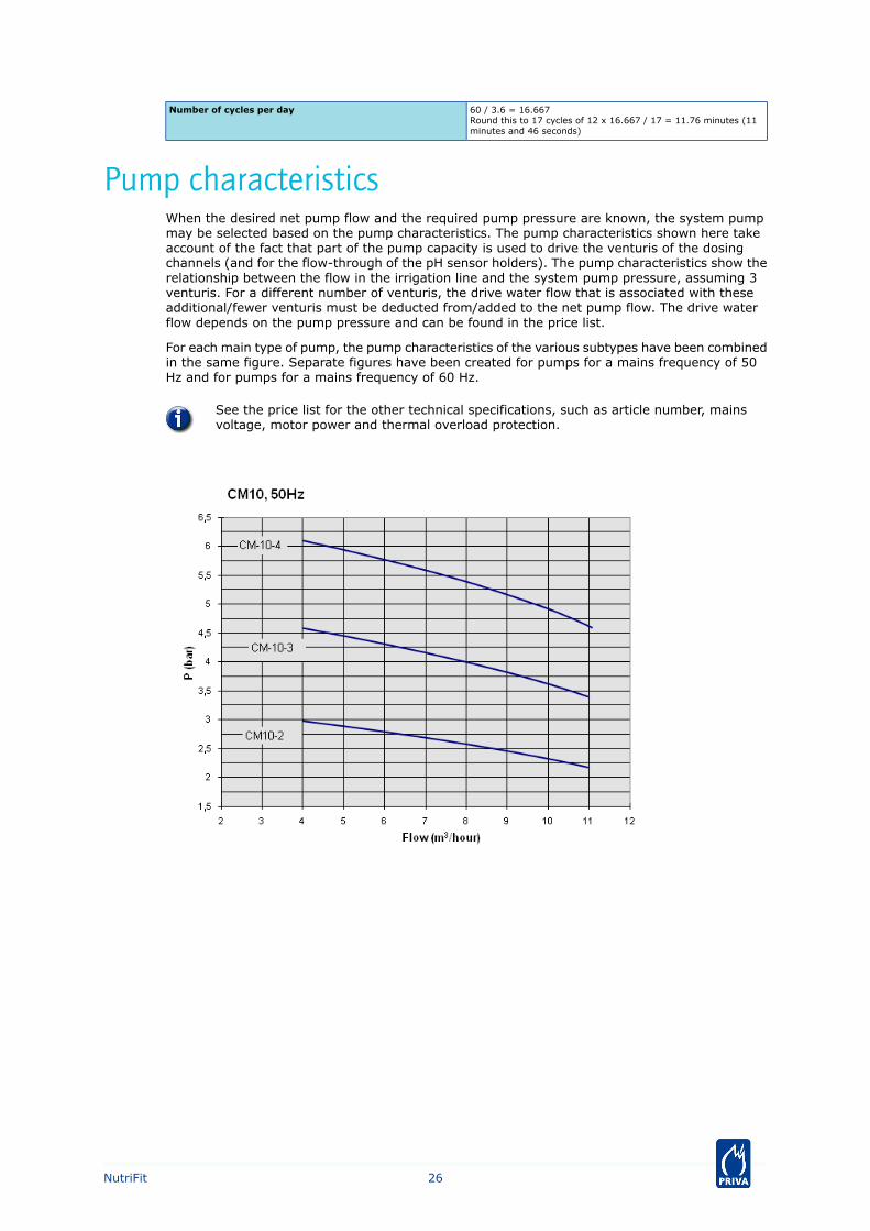
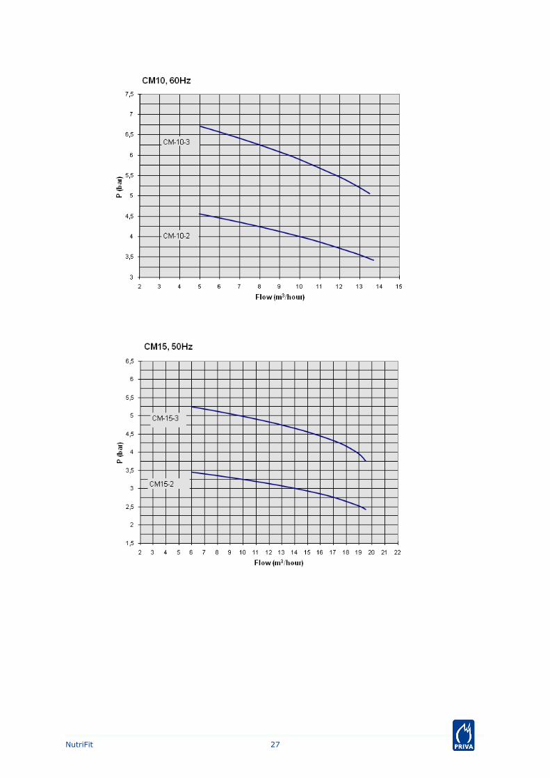
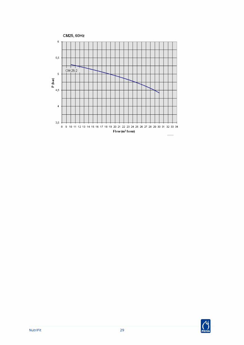
Pump characteristicsWhen the desired net pump flow and the required pump pressure are known, the system pumpmay be selected based on the pump characteristics. The pump characteristics shown here takeaccount of the fact that part of the pump capacity is used to drive the venturis of the dosingchannels (and for the flow-through of the pH sensor holders). The pump characteristics show therelationship between the flow in the irrigation line and the system pump pressure, assuming 3venturis. For a different number of venturis, the drive water flow that is associated with theseadditional/fewer venturis must be deducted from/added to the net pump flow. The drive waterflow depends on the pump pressure and can be found in the price list.
For each main type of pump, the pump characteristics of the various subtypes have been combinedin the same figure. Separate figures have been created for pumps for a mains frequency of 50Hz and for pumps for a mains frequency of 60 Hz.
See the price list for the other technical specifications, such as article number, mainsvoltage, motor power and thermal overload protection.
26NutriFit
27NutriFit

28NutriFit
29NutriFit

EC sensors
Measuring tube with 2 EC sensors
In order to control and to monitor the electrical conductivity (EC) and so the concentration offertilisers in the irrigation water, the fertiliser dosing unit is equipped with 2 ECtemperature-compensated sensors. There is an important advantage of using 2 sensors: theprocess computer is able to monitor the correct functioning of the sensors by comparing bothmeasurements. If everything is all right, both measurements provide the same value at all times.Contamination or other influences may cause the values to deviate from one another. Then, it isno longer clear which value is right. This may cause an incorrect quantity of fertilisers being dosed,possibly causing crop damage. In case of a mutual deviation of the EC measurements, the processcomputer will stop the make-up of irrigation water and alert the user by an alarm signal. By this,crop damage is prevented.
Technical specifications for the EC sensor can be found in the manual of this sensor.
30NutriFit
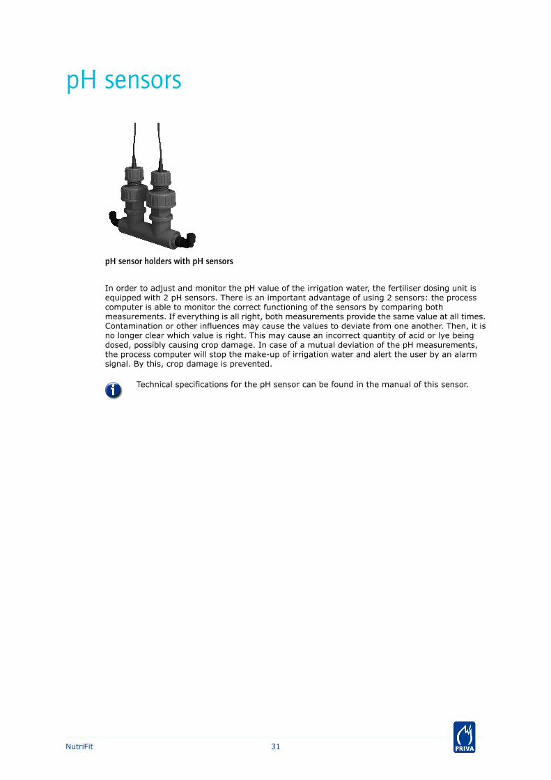
pH sensors
pH sensor holders with pH sensors
In order to adjust and monitor the pH value of the irrigation water, the fertiliser dosing unit isequipped with 2 pH sensors. There is an important advantage of using 2 sensors: the processcomputer is able to monitor the correct functioning of the sensors by comparing bothmeasurements. If everything is all right, both measurements provide the same value at all times.Contamination or other influences may cause the values to deviate from one another. Then, it isno longer clear which value is right. This may cause an incorrect quantity of acid or lye beingdosed, possibly causing crop damage. In case of a mutual deviation of the pH measurements,the process computer will stop the make-up of irrigation water and alert the user by an alarmsignal. By this, crop damage is prevented.
Technical specifications for the pH sensor can be found in the manual of this sensor.
31NutriFit
Flow sensor (litre counter)
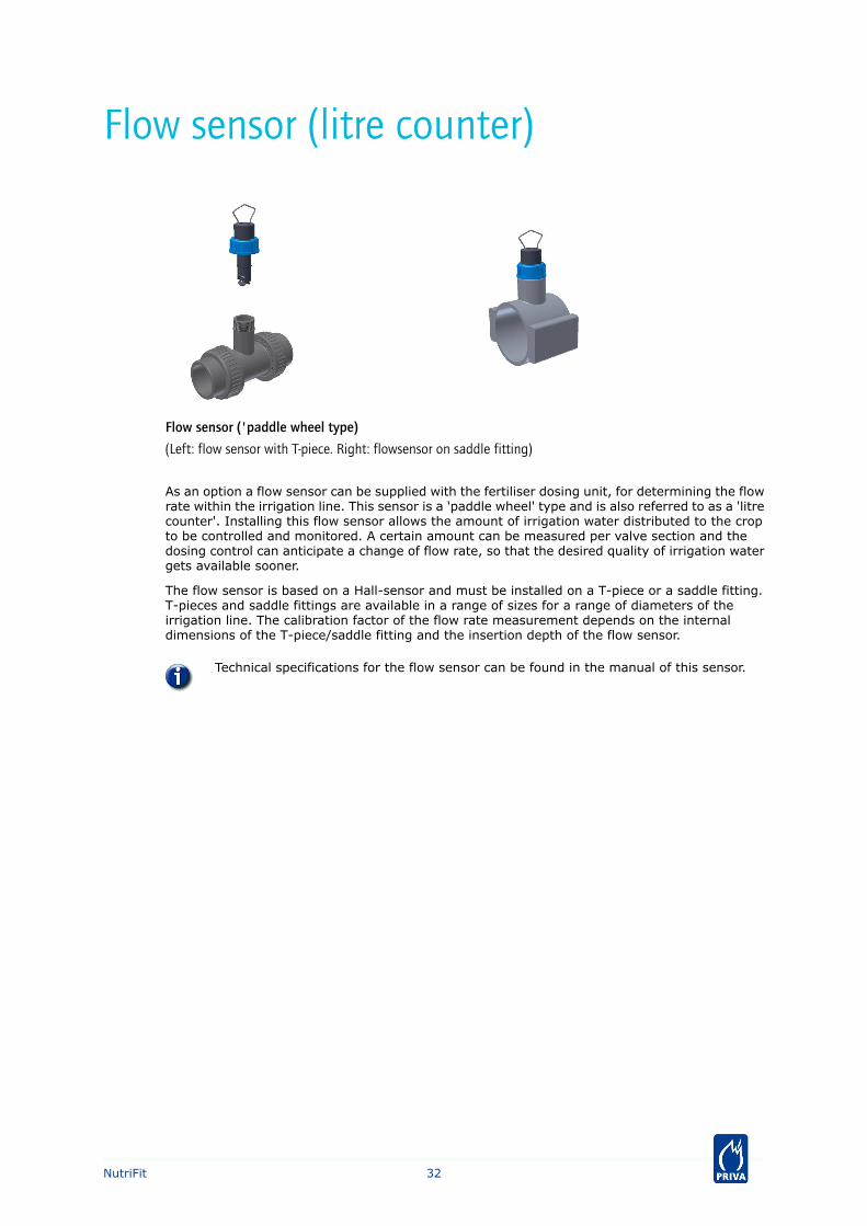
Flow sensor ('paddle wheel type)
(Left: flow sensor with T-piece. Right: flowsensor on saddle fitting)
As an option a flow sensor can be supplied with the fertiliser dosing unit, for determining the flowrate within the irrigation line. This sensor is a 'paddle wheel' type and is also referred to as a 'litrecounter'. Installing this flow sensor allows the amount of irrigation water distributed to the cropto be controlled and monitored. A certain amount can be measured per valve section and thedosing control can anticipate a change of flow rate, so that the desired quality of irrigation watergets available sooner.
The flow sensor is based on a Hall-sensor and must be installed on a T-piece or a saddle fitting.T-pieces and saddle fittings are available in a range of sizes for a range of diameters of theirrigation line. The calibration factor of the flow rate measurement depends on the internaldimensions of the T-piece/saddle fitting and the insertion depth of the flow sensor.
Technical specifications for the flow sensor can be found in the manual of this sensor.
32NutriFit
Supply water quality
Composition and pH valueThe dosing unit adds acid or lye to the supply water to:• regulate the pH value of the irrigation water;• chemically mix (homogenise) the irrigation water in the mixing tank in an optimum manner;• allow a chemical reaction to take place (convert bicarbonate into carbon dioxide).
The pH value of the irrigation water must be between 5.2 and 6.2, depending on the crop andgrowing medium.
Supply water consists of (a combination of) rain water, drinking water, bore hole water,downstream mill water, river water or reverse osmosis water, typically mixed with (disinfected)drain water. The variety of chemical elements in the supply water determine not only thecomposition and the pH value of the supply water but also whether or not the supply water canbe used as irrigation water once fertiliser and acid or lye have been added using the dosing unit.
Influence of bicarbonateIt is important that the quantity of HCO3
- (bicarbonate) in the supply water is established bymeans of water analysis. Bicarbonate has a buffering effect on the pH value and affects theoperation of the acid dosing control in the dosing unit:• An optimum quantity of HCO3
- in the supply water helps to ensure that plants receive irrigationwater with a reliable and accurate pH value via the dosing unit. The correct pH value of theirrigation water is necessary for the good take up of fertilisers by the plant.
• An excessively low quantity of HCO3- causes the pH control to become unstable.
• An (excessively) high amount of HCO3- leads to an (excessively) slow chemical reaction in
the mixing tank. Dosing acid neutralises HCO3-, with a quantity of CO2 (carbon dioxide) being
generated. This CO2 must be released from the irrigation water in the open mixing tank viacontact with the ambient air. The greater the quantity of HCO3
-, the longer before theneutralisation reaction is completed. If the reaction is not completed within the exposure timein the mixing tank, a problem arises: he unit will indeed be supplying irrigation water withthe desired pH, but there will still be CO2 in it. In the closed irrigation line this CO2 cannot bereleased into the ambient air, and reaches the plant. There it will be released into the ambientair, causing the pH to rise. In this case, the pH at the plants will not therefore be the sameas the pH that was set on the unit.
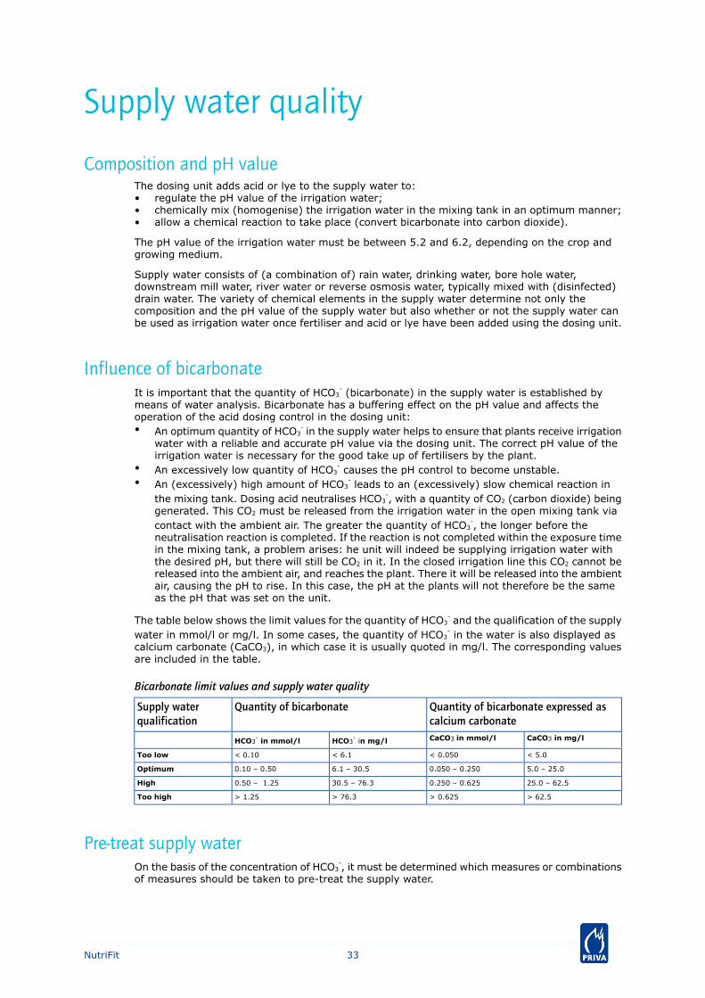
The table below shows the limit values for the quantity of HCO3- and the qualification of the supply
water in mmol/l or mg/l. In some cases, the quantity of HCO3- in the water is also displayed as
calcium carbonate (CaCO3), in which case it is usually quoted in mg/l. The corresponding valuesare included in the table.
Bicarbonate limit values and supply water quality
Quantity of bicarbonate expressed ascalcium carbonate
Quantity of bicarbonateSupply waterqualification
CaCO3 in mg/lCaCO3 in mmol/lHCO3- in mg/lHCO3
- in mmol/l
< 5.0< 0.050< 6.1< 0.10Too low
5.0 – 25.00.050 – 0.2506.1 – 30.50.10 – 0.50Optimum
25.0 – 62.50.250 – 0.62530.5 – 76.30.50 – 1.25High
> 62.5> 0.625> 76.3> 1.25Too high
Pre-treat supply waterOn the basis of the concentration of HCO3
-, it must be determined which measures or combinationsof measures should be taken to pre-treat the supply water.
33NutriFit

Supply water with too low a concentration of bicarbonateWhen using reverse osmosis water, but in some cases rain water also, too low a quantity of HCO3
-
( < 0.10 mmol/l) may be deemed to exist in the supply water. Dosing acid may give rise to anunstable chemical reaction in the irrigation water.
This unstable reaction can be stabilised by taking one of the following measures, or acombination thereof:• Add disinfected drain water, which typically contains bicarbonate, to the supply water
(via an EC pre-control).• Add a small quantity of drinking water or bore hole water (1 .. 2 %) to the supply
water via an electric valve with small diameter.• Add a small quantity of bicarbonate to one of the fertiliser solutions. This can be done,
for example, by replacing 1 % of caustic potash with an equal quantity of potassiumcarbonate (KHCO3) or calcium carbonate (K2CO3).
Supply water with a high concentration of bicarbonateWhen using bore hole water, river water and drinking water, the supply water may sometimescontain a high concentration of HCO3
- (0.50 .. 1.25 mmol/l). Dosing acid may then result in therebeing insufficient time to neutralise the bicarbonate.
Stabilisation is possible by correcting the pH value of the supply water by accuratelydosing a fixed quantity of acid per m3 of supply water using an acid dosing pump connectedto an accurate litre counter.
Supply water with too high a concentration of bicarbonateIn many cases, too high a concentration of HCO3
- (> 1.25 mmol/l) may be deemed to exist in thesupply water when using bore hole water, river water and drinking water. Dosing acid may thenresult in there being insufficient time to neutralise the bicarbonate.
Stabilisation is possible by pre-treating the supply water using a Priva Neutralizer withan acid injection and aeration system. The treated supply water is then stored in a stocktank.
34NutriFit

Supply water pressure and capacityThe supply water pressure on the inlet valve of the fertiliser dosing unit shall be between 2.5 and4.0 bar. The inlet valve can not control the admittance of supply water if the supply water pressureis lower than 2.0 bar. The inlet valve may start leaking if the supply water pressure is higher than4,0 bar. If necessary, use a supply water pump to generate pressure or a pressure regulator tolower the pressure.
Pressure on the inlet valve may only be present if the fertiliser dosing unit is delivering irrigationwater. If a closed inlet valve is exposed to pressure too long, it may start leaking. Therefore,install an electric valve in the supply water line or let the supply water pump be controlled fromthe unit.
The capacity of the supply water shall be at least equal to the net capacity of the system pump(preferably somewhat more).
35NutriFit
FiltersUse filters to filter organic dirt and solid particles out of the water. The choice of a sand filterand/or screen filter will depend on the quality of the supply water.
Sand filterUse a sand filter if the supply water contains large amounts of organic dirt such as algae or plantremnants.
In general, the following operational conditions apply to a sand filter:• The flow rate of the water through the sand filter is approx. 40 .. 50 m/h.• The rinse water speed must be approx. 40 .. 50 m/h to achieve an expansion of around 15 %
in the bed of sand via an additional backwashing pump.• The size of sand grains is approx. 1 .. 2 mm.• The thickness of the bed of sand is approx. 40 cm.
Other points to consider:• On account of the hydraulic resistance, always position a sand filter at the discharge side of
pump.• In the event of a pressure difference of approx. 0.5 bar over the bed of sand, the sand filter
must be rinsed. To do this, you require an additional backwashing pump.• A multi-layer or multimedia filter can be used for large quantities of suspended particles, such
as a filter with layers of anthracite, sand and gravel. For more information, please consultthe sand filter supplier's manual.
• If a standstill of the unit during the backwashing of the filter is a problem, consider multiplefilters connected in parallel. In this way there is always enough filter capacity if one of thefilters is being backwashed.
Screen filterUse a screen filter ('sieve filter') when the supply water contains a large number of hard andcoarse particles.
In general, the following operational conditions apply to a screen filter:• The flow rate through the filter must be adjusted to the type of filter.• It must be possible to clean the filter automatically or manually during use.• The filter must be made from SST or a synthetic material with a passage size < 75 .. 500
µm, depending on the type of supply water and type of irrigation system (dripper or sprinkler).
• Clean filters on a regular basis. The frequency depends on the degree of contaminationof the supply water. Consult the user instructions or contact the supplier of the filterconcerned.
• If the filter is installed on the distribution side of the unit, a dirt filter with a maximumpassage size of 2 mm must be installed on the supply side.
Automatic rinsing of a filter is not possible with the NutriFit ISA.
Because a screen filter usually has a relatively coarse mesh size (especially if it is a dirt filter),the hydraulic resistance is low and the filter can also be positioned on the suction side of thepump. On account of the hydraulic resistance, a fine-meshed screen filter must be positioned onthe discharge side of the pump.
36NutriFit

Position of the filter relative to the unitThere are many factors that determine whether a filter should be positioned on the supply side,on the distribution side or possibly on both sides of the unit. Some considerations:• The smaller the openings on the sprinklers or drippers of the irrigation system, the easer it
is for them to become clogged and the more important it is to ensure good filtration.• Although it may seem logical to fine filter the supply water (thus protecting both the unit and
the distribution system against particles), it is often better to position a relatively coarse filter(screen filter) on the supply side of the unit and a fine filter on the distribution side. This isbecause particles can also be produced in the unit, for instance as a result of algae growthor sediment or the depositing of fertilisers (especially when the unit is at a standstill). Inaddition, a fine filter may cause problems with the pump on the unit on account of the highhydraulic resistance.
• If recipes are changed frequently, a sand filter on the distribution side will be a disadvantage.This is because the sand filter will have to be frequently rinsed, resulting in a repeated lossof irrigation water.
37NutriFit

Fertiliser supplyThe dimensions of all components that are installed for fertiliser storage and the entire line pathbetween the fertiliser stock tank and the dosing channel must be completely identical for all tanksto support a balanced level of fertiliser suction. Place the tanks, lines and the fertiliser dosing unitwithin a containment provision to receive the chemical substances in the event of a leakage. Thefollowing further aspects should be taken into account when installing fertiliser, acid and/or lyetanks for the fertiliser dosing unit:
Fertiliser and acid or lye tanksEnsure that he bottom of the fertiliser and acid or lye tanks is not beneath the level of theconnections of the dosing channels.
If balance level control is desired (and possible), then provide the fertiliser tanks with level sensors.
Fertiliser and acid or lye linesEnsure that that the supply lines between the fertiliser tank and the fertiliser dosing unit are asshort as possible for a maximum dosing capacity. Ensure in all cases that the pipes are shorterthan 8 m.
Ensure that eventual air bubbles in the lines can escape via the dosing channels, and do not gettrapped at a highest point in the line.
The hose connection for the fertiliser supply is fitted with a ribbed hose coupling having an externaldiameter of Ø 16 mm. For the fertiliser supply to 300 l/h dosing channels, use reinforced PVCwater hose of Ø 15 x Ø 20.5 mm. Use stainless steel hose clamps (SS 316; steel number: 1.4401).
Use EPDM sealing material to be resistant to weak acid and alkaline solutions.
The dosing channels with a rotameter are suitable up to 3 % (weight percent) nitric acid. Thedosing channels without rotameter are suitable up to 10 % (weight percent) nitric acid.
Install valves in the fertiliser and acid or lye supply lines in order to be able to safely carry outmaintenance (such as cleaning filters and venturi's).
Fertiliser filtersFiltering the fertiliser solutions is crucial in preventing blockages and damage in the dosingchannels. Incompletely dissolved fertilisers, sand grains or crystals that have formed in the supplypipes can damage the dosage valve seating and the dosing valve membrane. These defects mustbe prevented by careful filtering and are not covered by the warranty. Therefore install a filter inthe fertiliser supply line at the side of the stock tank, having a passage size of < 500 µm. Andensure that a filter is present at the side of the dosing channel, having a passage size of < 130 µm(either built in the dosing channel or installed directly before the connection of the dosing channel).Select filters that can be easily cleaned, and having enough surface so that they do not need tobe cleaned too often.
Do not use a filter on lines containing nitric acid at a concentration > 10 % (weightpercent). The filters are not resistant to this. Ensure that no dirt gets into the nitric acidtank and that filtered nitric acid is supplied.
38NutriFit
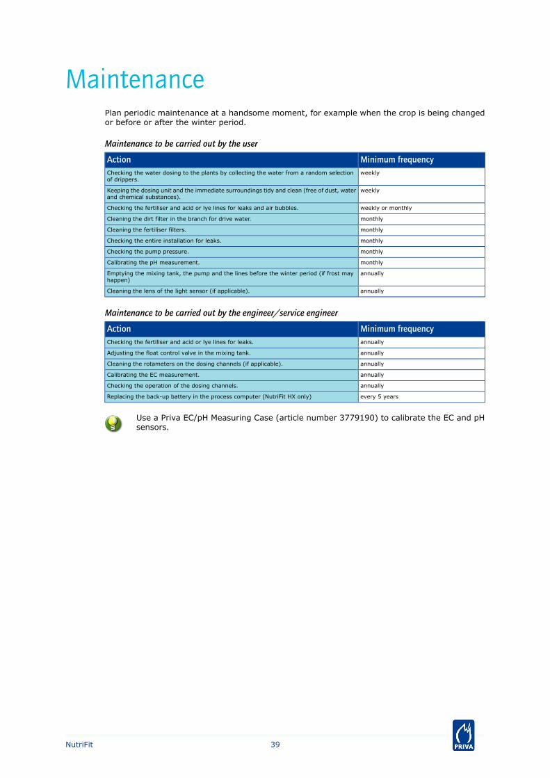
MaintenancePlan periodic maintenance at a handsome moment, for example when the crop is being changedor before or after the winter period.
Maintenance to be carried out by the user
Minimum frequencyActionweeklyChecking the water dosing to the plants by collecting the water from a random selection
of drippers.
weeklyKeeping the dosing unit and the immediate surroundings tidy and clean (free of dust, waterand chemical substances).
weekly or monthlyChecking the fertiliser and acid or lye lines for leaks and air bubbles.
monthlyCleaning the dirt filter in the branch for drive water.
monthlyCleaning the fertiliser filters.
monthlyChecking the entire installation for leaks.
monthlyChecking the pump pressure.
monthlyCalibrating the pH measurement.
annuallyEmptying the mixing tank, the pump and the lines before the winter period (if frost mayhappen)
annuallyCleaning the lens of the light sensor (if applicable).
Maintenance to be carried out by the engineer/service engineer
Minimum frequencyActionannuallyChecking the fertiliser and acid or lye lines for leaks.
annuallyAdjusting the float control valve in the mixing tank.
annuallyCleaning the rotameters on the dosing channels (if applicable).
annuallyCalibrating the EC measurement.
annuallyChecking the operation of the dosing channels.
every 5 yearsReplacing the back-up battery in the process computer (NutriFit HX only)
Use a Priva EC/pH Measuring Case (article number 3779190) to calibrate the EC and pHsensors.
39NutriFit

Warranty and safety
WarrantyPriva fertiliser dosing units are delivered with the components as described in this productdescription. However, Priva maintains the right to make necessary alterations to the design.
Any warranty claim will be invalid if the unit has not been installed and used according to theguidelines given in this product description and in the manual for installation and operation. Forthe other conditions, refer to the general delivery conditions of Priva (these will be sent to youon request).
SafetyMainly because of the combination of chemical substances, water, and electricity, it is importantthat the fertiliser dosing units are installed and operated in accordance with the safety instructionsof Priva and the locally applicable regulations. The manuals on installation and operation paymuch attention to the subject of safety.
40NutriFit
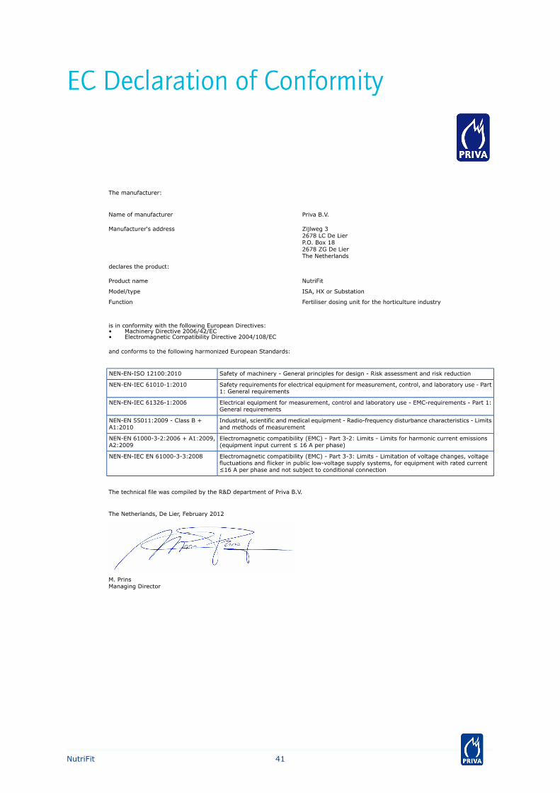
EC Declaration of Conformity
The manufacturer:
Priva B.V.Name of manufacturer
Zijlweg 32678 LC De LierP.O. Box 182678 ZG De LierThe Netherlands
Manufacturer's address
declares the product:
NutriFitProduct name
ISA, HX or SubstationModel/type
Fertiliser dosing unit for the horticulture industryFunction
is in conformity with the following European Directives:• Machinery Directive 2006/42/EC• Electromagnetic Compatibility Directive 2004/108/EC
and conforms to the following harmonized European Standards:
Safety of machinery - General principles for design - Risk assessment and risk reductionNEN-EN-ISO 12100:2010
Safety requirements for electrical equipment for measurement, control, and laboratory use - Part1: General requirements
NEN-EN-IEC 61010-1:2010
Electrical equipment for measurement, control and laboratory use - EMC-requirements - Part 1:General requirements
NEN-EN-IEC 61326-1:2006
Industrial, scientific and medical equipment - Radio-frequency disturbance characteristics - Limitsand methods of measurement
NEN-EN 55011:2009 - Class B +A1:2010
Electromagnetic compatibility (EMC) - Part 3-2: Limits - Limits for harmonic current emissions(equipment input current ≤ 16 A per phase)
NEN-EN 61000-3-2:2006 + A1:2009,A2:2009
Electromagnetic compatibility (EMC) - Part 3-3: Limits - Limitation of voltage changes, voltagefluctuations and flicker in public low-voltage supply systems, for equipment with rated current≤16 A per phase and not subject to conditional connection
NEN-EN-IEC EN 61000-3-3:2008
The technical file was compiled by the R&D department of Priva B.V.
The Netherlands, De Lier, February 2012
M. PrinsManaging Director
41NutriFit

42NutriFit


Priva
Zijlweg 3
2678 LC
P.O. Box 18
2678 ZG
De Lier
The Netherlands
T +31 174 522 600
F +31 174 522 700
www.priva.nl
3789674_01.0
05_07-2
012