Embed Size (px)
Citation preview
Rapport Rapporttittel Rapport nummer PSA Well Integrity Survey, Phase 1 summary report -
Gradering þ Offentlig o Unntatt offentlighet
o Begrenset o Fortrolig
o Strengt fortrolig
Involverte Organisasjonsenhet Forfatter/saksbehandler F-Boring & brønnteknologi B.Vignes, J.Andreassen, S.A.Tonning Deltakere i revisjonslaget Dato F-B&B + konsulenter (AGR/RCC) 30.6.2006 Rapport og prosjektinformasjon Sammendrag The Petroleum Safety Authority (PSA) has from February 2006 to June 2006 performed a Well Integrity Survey as a “pilot project” that is primarily based on supervisory audits and requested input from 7 operating companies and pre-selected offshore facilities/wells.
The wells assessed were primarily a representative selection of producers and injectors with variation of age and development categories.
A number of well-related failures and shortfalls have been identified in the past with significant impact and potential for serious accidents. Sub-standard operations have in some cases been conducted in spite of the Management Regulations requirements to barriers (Section 2, Barriers).
This pilot project (Phase 1) is based on input from every fifth “active” development well on the Norwegian Continental Shelf (NCS), which largely constitutes the basis for the evaluations of the well integrity status.
Key results from the audits are: • It has been confirmed that each company generally need to improve focus on well integrity issues. • Well integrity and barrier philosophy need common attention from the industry in order to comply with
the regulations, including premises relating to the 2 barrier concept, and thereby reducing the potential for well related accidents.
• The pilot project indicates that averagely 18 % of the production- and injection wells were to some degree impaired by well integrity issues, including 7% full shut in. The impairments are clearly representing a generous potential for improvements both to HSE and production.
• The company management should also improve focus on well integrity issues in their supervisory audits. • There is a need to align with a common way of documenting well integrity within the industry. The
methods for describing the well barriers/barrier envelopes vary in the industry and even within the same operating company.
• There is a general lack of user friendly access to and quality of the well integrity data. • The hand-over process and related documentation need to be improved. • Improved attention on verification and condition monitoring of well barriers and well integrity is needed. • The industry need to further develop/ acquire suitable technology for condition monitoring of wells to
improve on systematic/ preventive maintenance and to keep better control on degradation mechanisms.
• There is a need for improved competence and training involving personnel both from the Operators and Contractors.
The operating companies involved appeared positive to the PSA initiative for this pilot project and there seems to be a common understanding and agreement that well integrity is an area that requires improved attention. For this purpose, a Phase 2 of this project will be discussed with the operating companies during autumn 2006. Norske emneord Well integrity, brønnintegritet, barriers, barrierer, brønnbarrierer

2 of 23
Well Integrity Survey, Phase 1, 2006 Revision 21.06.2006
Prosjekttittel Prosjektnr Well integrity survey phase1 - 4010 - 705610 Brønnintegritet Antall sider Opplag 24 -
PSA Well Integrity Survey (Phase 1), Summary Report
Contents:
Contents of the PSA Well Integrity Survey (Phase 1) Summary Report ................. 2 Introduction .......................................................................................................... 3 Scope of Work...................................................................................................... 4 Project method and execution ............................................................................... 5 Results................................................................................................................ 10 Conclusions ........................................................................................................ 21 Project phase2 - Discussion................................................................................. 22 References and abbreviations.............................................................................. 24
3 of 23
Well Integrity Survey, Phase 1, 2006 Revision 21.06.2006
Introduction Several well incidents have been reported in the past, with significant impact and potential for serious accidents (several companies – various well categories). This could typically be a result from ageing effects or wrong design, unclear understanding of barriers, weaknesses in well design and planning processes, insufficient validation of premises, well convertions and other reasons. Direct complaints from work force representatives indicate varied comprehension of well barriers, lack of overview, including variable approaches for corrective actions. It has been difficult for key personnel to get access to essential well-data/premises if/when well control situations occur. There are also differences in the way the well integrity/ barrier concept is being implemented.
There are cases with insufficient systematic control of the technical capability of entire “barrier envelopes” and limited standardization according to the NORSOK D-010 (Rev.3) recommendations for well barriers. Examples comprise design capabilities exceeded in operation, excessive exposure time with intentions for increased oil recovery, and non-technical “benchmarking” and missing continuity from design through operation and maintenance.
PSA has experienced shortcomings for handling non-conformities and management of changes / conversions and lack of recognition of the entire well barrier envelope with elements as “safety critical equipment”, which demands systematic maintenance and control.
Further, there are indications on insufficient transfer of critical information during license acquisitions and change of operator, and a general need for improved “hand-over”–documents in operations
In order to get a better picture of the well integrity status, PSA initiated this spring a “pilot project”, Phase 1, based on “spot checks” of selected wells from some of the oil companies.
Companies involved have taken part in clarification meeting(s) and has received a separate report describing the general findings related to their input.
A continuation work is aimed to be in cooperation with the operating companies based on the results from the audits and this pilot project (Phase 1).
Scope of Work The following was used as scope of work for the audits and phase1 pilot project:
“The phase 1 pilot project shall be initiated and executed by the PSA drilling & well technology discipline with assistance of other PSA disciplines as required and consultants from AGR/RCC for specific tasks”.
This entailed plans to execute audits towards 7 operating companies and on the initial basis of 12 installations with 581 wells. The audits were conducted towards representative operating companies and a sufficient number of wells to enable a general evaluation. The audits were based on identical questionnaires and followed through by clarification meeting(s) with each individual company as needed.
4 of 23
Well Integrity Survey, Phase 1, 2006 Revision 21.06.2006
The consultants from AGR/RCC assisted PSA with evaluation of barrier schematics and general discussions based on the replies prior to and after the applicable audits.
Dedicated audit reports were prepared for each operating company comprised.
An anonymous summary report (this report) was prepared after the 7 audits were performed, for experience transfer to the industry in general. This report will be presented on the PSA internet site.
Project method and execution The plan for a pilot project (Phase 1) was presented to the OLF-Drilling Managers Forum in a meeting 16.2.2006 in order to promote and to get initial feedback prior to launching it. The focus on well barriers and plans for a pilot project was positively responded to by the participants of that meeting.
Seven selected operating companies received an audit notification from PSA at the end of February 2006.
The candidates were: BP: Valhall DP ConocoPhillips: Ekofisk X and Eldfisk A ExxonMobil: Jotun B Hydro: Grane, Njord and Oseberg Øst Shell: Draugen Statoil: Statfjord C w/satellites (North and East), Veslefrikk and Åsgard. Talisman: Gyda
The selected companies were requested to provide status of well integrity issues for certain pre-selected offshore facilities/ wells as of 1.3.2006.
All the companies confirmed that the well status as of 1.3.2006 provided a representative picture of the existing well-situation for the selected installations.
From a total number of development wells (2682) on the NCS, 12 installations with associated 581 wells were originally identified as potential candidates for the pilot project. After the initial feedback from the industry, the relevant number of well candidates was reduced in order to carry out the planned assessment:
1. From the development wells initially addressed, the P&A category and other “non productive” wells were excluded in order to focus on “active” wells and “potentially active wells”. The production- and, injection wells (in total 406 wells) were thereafter assessed on the basis reported barrier shortfalls.
2. Every 5th wells on an installation were then picked for the particular assessment of barrier schematics and hand-over documents, within general guiding limits of maximum 3 producers, 2 injectors and 1 disposal well per installation (in total 58 wells).
3. Well data/ information associated with uncertainties were subject to relevant corrections during the following clarification meetings.
5 of 23
Well Integrity Survey, Phase 1, 2006 Revision 21.06.2006
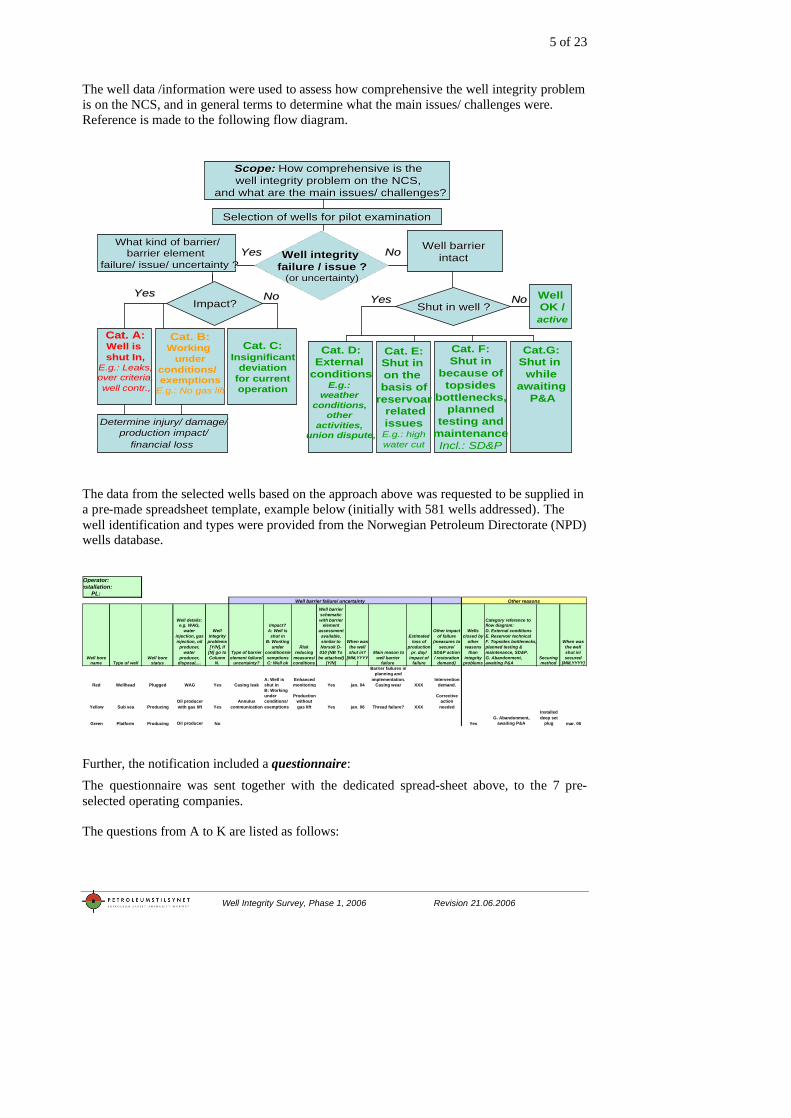
The well data /information were used to assess how comprehensive the well integrity problem is on the NCS, and in general terms to determine what the main issues/ challenges were. Reference is made to the following flow diagram.
Scope:Scope: How comprehensive is theHow comprehensive is thewell integrity problem on the NCS,well integrity problem on the NCS,
and what are the main issues/ challenges?and what are the main issues/ challenges?
Selection of wells for pilot examination Selection of wells for pilot examination
Well integrity Well integrity failure / issue ?failure / issue ?
(or uncertainty)(or uncertainty)
NoNoYesYesWhat kind of barrier/What kind of barrier/
barrier element barrier element failure/ issue/ uncertainty ?failure/ issue/ uncertainty ?
Well barrier Well barrier intact intact
Impact?Impact?YesYes
Cat. A:Well is shut In,
E.g.: Leaks,over criteria,well contr.,
Cat. B:Working
underconditions/ exemptions
E.g.: No gas lift
NoNo
Cat. F:Shut in
because oftopsides
bottlenecks,planned
testing andmaintenanceIncl.: SD&P
Cat.G:Shut in
whileawaiting
P&A
Cat. C:Insignificant
deviationfor currentoperation
Determine injury/ damage/Determine injury/ damage/production impact/production impact/
financial lossfinancial loss
Shut in well ?Shut in well ?NoNoYesYes Well
OK /active
Cat. D:External
conditionsE.g.:
weather conditions,
other activities,
union dispute,
Cat. E:Shut in on the basis of
reservoarrelatedissuesE.g.: highwater cut
The data from the selected wells based on the approach above was requested to be supplied in a pre-made spreadsheet template, example below (initially with 581 wells addressed). The well identification and types were provided from the Norwegian Petroleum Directorate (NPD) wells database.
Operator:
Installation:PL:
Well bore name Type of well
Well bore status
Well details: e.g. WAG,
water injection, gas injection, oil
producer, water
producer, disposal,…
Well Integrity
problems [Y/N], If
[N] go to Column
N.
Type of barrier element failure/
uncertainty?
Impact? A: Well is
shut in B: Working
under conditions/exemptions C: Well ok
Risk reducing
measures/ conditions
Well barrier schematic with barrier
element assessment
available, similar to Norsok D-010 (NB To
be attached) [Y/N]
When was the well shut in?
[MM,YYYY]
Main reason to well barrier
failure
Estimated loss of
production pr. day/
impact of failure
Other impact of failure
(measures to secure/
SD&P action / restoration
demand)
Wells closed by
other reasons
than integrity
problems
Category reference to flow diagram: D. External conditions E. Reservoir technical F. Topsides bottlenecks, planned testing & maintenance, SD&P. G. Abandonment, awaiting P&A
Securing method
When was the well shut in/ secured
[MM,YYYY]
Red Wellhead Plugged WAG Yes Casing leakA: Well is shut in
Enhanced monitoring Yes jan. 04
Barrier failures in planning and
implementation. Casing wear XXX
Intervention demand.
Yellow Sub sea ProducingOil producer with gas lift Yes
Annulus communication
B: Working under conditions/ exemptions
Production without gas lift Yes jan. 06 Thread failure? XXX
Corrective action
needed
Green Platform Producing Oil producer No YesG. Abandonment,
awaiting P&A
Installed deep set
plug mar. 06
Well barrier failure/ uncertainty Other reasons
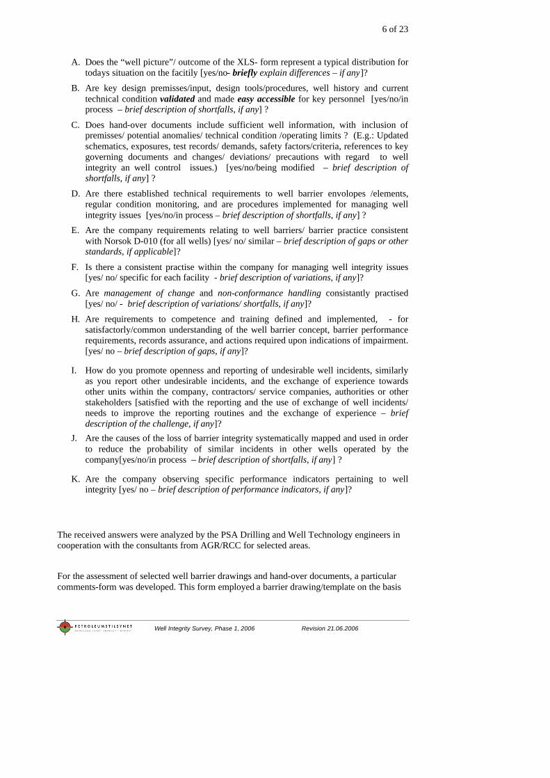
Further, the notification included a questionnaire: The questionnaire was sent together with the dedicated spread-sheet above, to the 7 pre-selected operating companies. The questions from A to K are listed as follows:
6 of 23
Well Integrity Survey, Phase 1, 2006 Revision 21.06.2006
A. Does the “well picture”/ outcome of the XLS- form represent a typical distribution for todays situation on the facitily [yes/no- briefly explain differences – if any]?
B. Are key design premisses/input, design tools/procedures, well history and current technical condition validated and made easy accessible for key personnel [yes/no/in process – brief description of shortfalls, if any] ?
C. Does hand-over documents include sufficient well information, with inclusion of premisses/ potential anomalies/ technical condition /operating limits ? (E.g.: Updated schematics, exposures, test records/ demands, safety factors/criteria, references to key governing documents and changes/ deviations/ precautions with regard to well integrity an well control issues.) [yes/no/being modified – brief description of shortfalls, if any] ?
D. Are there established technical requirements to well barrier envolopes /elements, regular condition monitoring, and are procedures implemented for managing well integrity issues [yes/no/in process – brief description of shortfalls, if any] ?
E. Are the company requirements relating to well barriers/ barrier practice consistent with Norsok D-010 (for all wells) [yes/ no/ similar – brief description of gaps or other standards, if applicable]?
F. Is there a consistent practise within the company for managing well integrity issues [yes/ no/ specific for each facility - brief description of variations, if any]?
G. Are management of change and non-conformance handling consistantly practised [yes/ no/ - brief description of variations/ shortfalls, if any]?
H. Are requirements to competence and training defined and implemented, - for satisfactorly/common understanding of the well barrier concept, barrier performance requirements, records assurance, and actions required upon indications of impairment. [yes/ no – brief description of gaps, if any]?
I. How do you promote openness and reporting of undesirable well incidents, similarly as you report other undesirable incidents, and the exchange of experience towards other units within the company, contractors/ service companies, authorities or other stakeholders [satisfied with the reporting and the use of exchange of well incidents/ needs to improve the reporting routines and the exchange of experience – brief description of the challenge, if any]?
J. Are the causes of the loss of barrier integrity systematically mapped and used in order to reduce the probability of similar incidents in other wells operated by the company[yes/no/in process – brief description of shortfalls, if any] ?
K. Are the company observing specific performance indicators pertaining to well integrity [yes/ no – brief description of performance indicators, if any]?
The received answers were analyzed by the PSA Drilling and Well Technology engineers in cooperation with the consultants from AGR/RCC for selected areas.
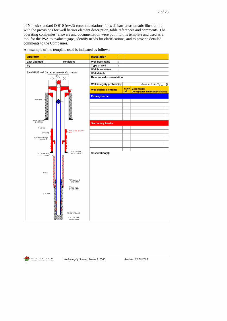
For the assessment of selected well barrier drawings and hand-over documents, a particular comments-form was developed. This form employed a barrier drawing/template on the basis
7 of 23
Well Integrity Survey, Phase 1, 2006 Revision 21.06.2006
of Norsok standard D-010 (rev.3) recommendations for well barrier schematic illustration, with the provisions for well barrier element description, table references and comments. The operating companies’ answers and documentation were put into this template and used as a tool for the PSA to evaluate gaps, identify needs for clarifications, and to provide detailed comments to the Companies.
An example of the template used is indicated as follows:
Operator : Installation : Last updated : Revision: Well bore name : By : Type of well :
Well bore status : Well details : Reference documentation: Well integrity problem(s) If any, indicated by _ S
Well barrier elements Table ref.
Comments (Acceptance criteria/Deviations)
Primary barrier
Secondary barrier
EXAMPLE well barrier schematic illustration
13 3/8" csg Shoe @1102 MD
5" Tubing
TRSCSSV 4 ½”
7" liner
4 ½” liner
TOC @4478 m MD
PBR (bottom) @ 4265 m MD
9 5/8" csg shoe @2691 m MD
7" Liner shoe @4401 m MD
4 ½” Liner shoe @4507 m MD
9 5/8" csg
TOP of Liner Hanger @2534 MD
TOC @3860 MD(CBL)
TOC 9 5/8" @ ???? MD
Observation(s):
8 of 23
Well Integrity Survey, Phase 1, 2006 Revision 21.06.2006
PSA’s immediate comments in similar work-forms as indicated by the template above were amended with the specific audit reports for information.
The clarification meetings were conducted as audits with the 7 operating companies involved in this pilot study, during the period from 5.5. to 23.5.2006. The purposes of the clarification meetings were:
ó To get a correct and uniform comprehension of received documentation about well integrity
ó If relevant, calibrate/ verify received documentation ó Communicate PSA`s immediate impression of received documentation.
ó Identify possible outstanding points with the company – clarify the path forward to conclude the pilot survey on well integrity
Information about PSA’s intentions regarding reporting was given.
9 of 23
Well Integrity Survey, Phase 1, 2006 Revision 21.06.2006
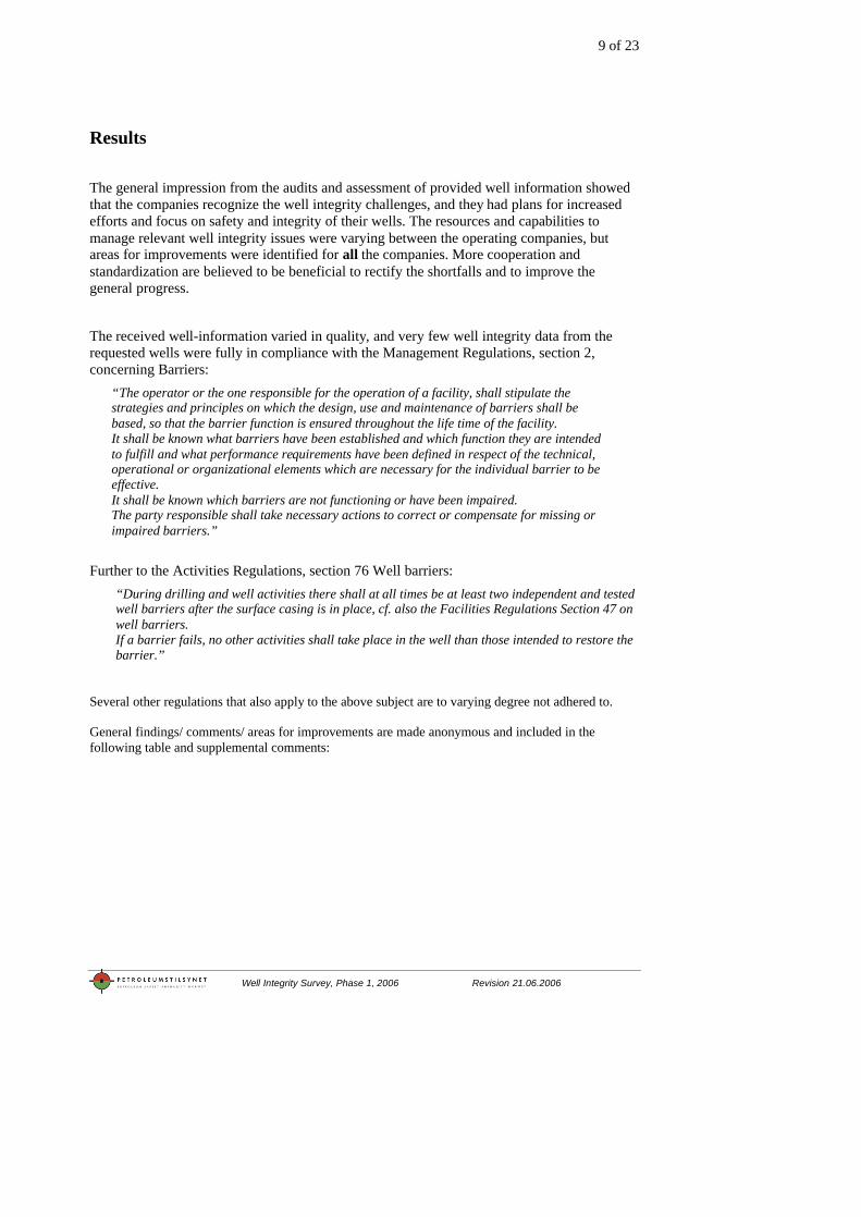
Results
The general impression from the audits and assessment of provided well information showed that the companies recognize the well integrity challenges, and they had plans for increased efforts and focus on safety and integrity of their wells. The resources and capabilities to manage relevant well integrity issues were varying between the operating companies, but areas for improvements were identified for all the companies. More cooperation and standardization are believed to be beneficial to rectify the shortfalls and to improve the general progress.
The received well-information varied in quality, and very few well integrity data from the requested wells were fully in compliance with the Management Regulations, section 2, concerning Barriers:
“The operator or the one responsible for the operation of a facility, shall stipulate the strategies and principles on which the design, use and maintenance of barriers shall be based, so that the barrier function is ensured throughout the life time of the facility. It shall be known what barriers have been established and which function they are intended to fulfill and what performance requirements have been defined in respect of the technical, operational or organizational elements which are necessary for the individual barrier to be effective. It shall be known which barriers are not functioning or have been impaired. The party responsible shall take necessary actions to correct or compensate for missing or impaired barriers.”
Further to the Activities Regulations, section 76 Well barriers: “During drilling and well activities there shall at all times be at least two independent and tested well barriers after the surface casing is in place, cf. also the Facilities Regulations Section 47 on well barriers. If a barrier fails, no other activities shall take place in the well than those intended to restore the barrier.”
Several other regulations that also apply to the above subject are to varying degree not adhered to. General findings/ comments/ areas for improvements are made anonymous and included in the following table and supplemental comments:

10 of 23
Well Integrity Survey, Phase 1, 2006 Revision 21.06.2006
Theme / subject:
Operator 1
Operator 2
Operator 3
Operator 4
Operator 5
Operator 6
Operator 7
A - Well data / response
B - Well documentation validated, easy accessible, user-friendly
Approved barrier information not easily accessible
Well information neither easily accessible nor user friendly
Well information neither easily accessible nor user friendly for older wells
Availability and quality of well information is limited due to storage in a variety of databases
Validation and availability of barrier information is not easy for the users
Well specific barrier schematics are missing
C - Handover documentation
Format and contents of handover documentation needs clarification
Format and contents of handover documentation needs clarification and coordination within company platforms
Format and contents of handover documentation needs clarification
Contents of handover documentation needs improvement
Format and contents of handover documentation needs clarification
Routines for and contents of handover documentation needs clarification
Handover documentation should include well drawings and barrier schematics
D - Condition monitoring, degradation mechanism
More active use of condition monitoring of barrier elements and downhole equipment should be evaluated
More active use of condition monitoring of barrier elements and downhole equipment should be evaluated
More active use of condition monitoring of barrier elements and downhole equipment should be evaluated
More active use of condition monitoring of barrier elements and downhole equipment should be evaluated
More active use of condition monitoring of barrier elements and downhole equipment should be evaluated
More active use of condition monitoring of barrier elements and downhole equipment should be evaluated
More active use of condition monitoring of barrier elements and downhole equipment should be evaluated
E - NORSOK D-010 use and adherence
Need for improved documentation of well barriers based on the principles in Norsok D010 rev3.
Need for improved documentation of well barriers based on the principles in Norsok D010 rev3.
Need for improved documentation of well barriers based on the principles in Norsok D010 rev3.
Need for improved documentation of well barriers based on the principles in Norsok D010 rev3.
Need for improved coordination of company internal documentation of well barriers based on the principles in Norsok D010 rev3
F - Unified approach in the company / between installations
Lack of knowledge of and involvement in major ongoing internal company barrier project
G - Management of change
H - Competence and training
Competence and training of relevant personnel related to well barriers onshore and offshore needs improvement
Competence and training of offshore operations personnel related to well barriers needs improvement
Lack of performance requirement, competence and training related to well integrity issues
Lack of performance requirement, competence and training related to well integrity issues
Competence and training of relevant personnel related to well barriers onshore and offshore needs improvement
Lack of involvement of contractors personnel in competence and training related to well barrier issues
Competence and training of relevant company personnel (located in Norway and abroad) working with well barriers needs improvement
I - Openness and experience transfer
Active use of experience transfer needs improvement
Active use of experience transfer needs improvement
Active use of experience transfer needs improvement
Active use of experience transfer needs improvement
J - Reliability analysis
Limited use of reliability analysis were used to improve understanding of failure mechanisms and robustness of well barriers/well barrier elements
Limited use of reliability analysis were used to improve understanding of failure mechanisms and robustness of well barriers/well barrier elements
Limited use of reliability analysis were used to improve understanding of failure mechanisms and robustness of well barriers/well barrier elements
Limited use of reliability analysis were used to improve understanding of failure mechanisms and robustness of well barriers/well barrier elements
K - Key performance indicators
Lack of routines/procedures for diagnosis and status for leaks in well barriers
L - Special challenges (optional )
Use of words and abbreviations in documents needs improvement and standardization
Use of words and abbreviations in documents needs improvement and standardization
Use of words and abbreviations in documents needs improvement and standardization
11 of 23
Well Integrity Survey, Phase 1, 2006 Revision 21.06.2006
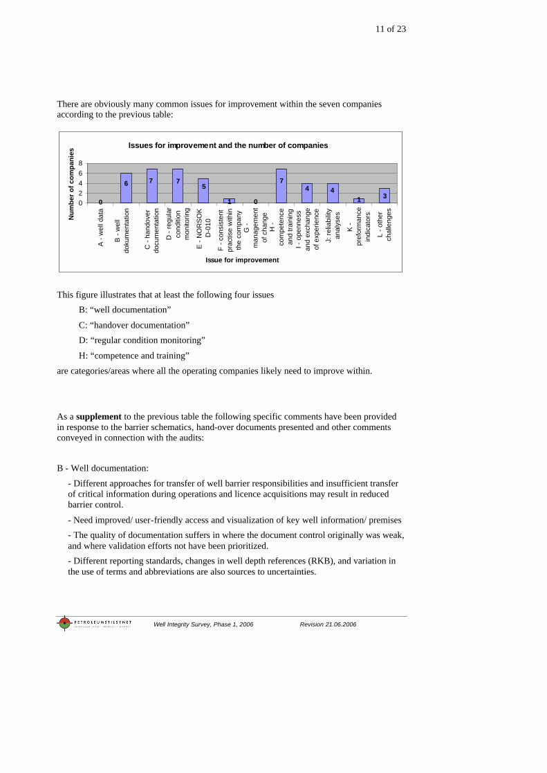
There are obviously many common issues for improvement within the seven companies according to the previous table:
Issues for improvement and the number of companies
3144
7
010
5776
02468
A -
wel
l dat
a
B -
wel
ldo
kum
enta
tion
C -
hand
over
docu
men
tatio
n
D -
regu
lar
cond
ition
mon
itorin
g
E -
NO
RS
OK
D-0
10
F - c
onsi
sten
tpr
actis
e w
ithin
the
com
pany
G -
man
agem
ent
of c
hang
eH
-co
mpe
tenc
ean
d tra
inin
gI -
ope
nnes
san
d ex
chan
geof
exp
erie
nce
J: re
liabi
lity
anal
yses
K -
pref
orm
ance
indi
cato
rs
L - o
ther
chal
leng
es
Issue for improvement
Num
ber o
f com
pani
es
This figure illustrates that at least the following four issues B: “well documentation”
C: “handover documentation” D: “regular condition monitoring”
H: “competence and training”
are categories/areas where all the operating companies likely need to improve within.
As a supplement to the previous table the following specific comments have been provided in response to the barrier schematics, hand-over documents presented and other comments conveyed in connection with the audits:
B - Well documentation:
- Different approaches for transfer of well barrier responsibilities and insufficient transfer of critical information during operations and licence acquisitions may result in reduced barrier control.
- Need improved/ user-friendly access and visualization of key well information/ premises - The quality of documentation suffers in where the document control originally was weak, and where validation efforts not have been prioritized. - Different reporting standards, changes in well depth references (RKB), and variation in the use of terms and abbreviations are also sources to uncertainties.
12 of 23
Well Integrity Survey, Phase 1, 2006 Revision 21.06.2006
C - Handover documentation:
- Several companies include pressure test verification charts in their handover documentation, without interpretation. These data could be several years old and do not necessarily represent the current status. Well integrity or well barrier schematic illustrations, verifications and how to monitor status, was not easy accessible.
- While completion schematics are typically updated and available, included in the handover documents, the barrier schematic illustrations and with descriptions don’t seem to receive similar focus.
D - Barrier requirements and Condition monitoring:
- Changes from established practice take generally (too) long time to implement
- Consideration to and evaluations of initial casing design for the lifetime of the well, and possible impact by changes to different well usage (example, from production to injection), appears to receive insufficient attention.
- While studies from the UK Sector identifies considerable shortfalls with structural integrity problems in surface-/ conductor – and riser arrangements as a growing problem for ageing ageing well constructions, - these issues seems to receive more limited attentions offshore Norway.
E - Comments related to Norsok D-010 familiarization and use: - The Norsok D-010 defined requirements/ guidelines, including the established well barrier philosophy, appears to be less known and adhered to than PSA expected at the time when the audits were conducted.
- The lack of information on well names, dates and revision numbers complicates easy overview of the status on well barriers. Color coding and descriptions of the barrier envelopes varies from company to company, but also within the same company.
- The barrier illustrations are in several cases not containing details on perforations, X-mas tree, cement presence, and in some cases lacking barrier elements. Such well details, and with possible inclusion of dimensions and depth data, could be considered for new/updated versions.
- Verification details of the casing cement barriers are often lacking. Hence, proper planned top of cement (TOC), packer setting depth and later proper zonal isolation for later plugging and abandonment (P&A) could imply uncertainties.
- Questionable recognition of PBRs, Sliding Side Doors (SSD), Side Pocket Mandrels with dummy and Gas Lift Valves as barriers elements. Questionable (high) positioning of ASVs and Production Packers in the wells were also noted. Casing connections suitability for gas lift.
G - Handling situations with discrepancies and changes with regard to well/operation premises
- Some variations and indications on shortfalls noted with regard to how (essential) information on exceptions and changes are conveyed to key personnel.
13 of 23
Well Integrity Survey, Phase 1, 2006 Revision 21.06.2006
H - Competence and training:
- The questionnaire revealed a need for strengthening knowledge, communication and requirements to well barriers and status. The companies generally expressed high interest in sharing / exchanging training material for practical use.
- Training sessions with case assessments seems to be a recognized approach that also contributes to experience transfer. In order to also strengthen the risk perception among this personnel, these training sessions may also be used to demonstrate how “regular” failure modes (impairment of one barrier) significantly raises the risk level.
14 of 23
Well Integrity Survey, Phase 1, 2006 Revision 21.06.2006
Numbers and figures from the study Number of wells drilled at the Norwegian Continental Shelf:
– Exploration: 1095 wells – Development: 2682 wells – Total: 3777 wells
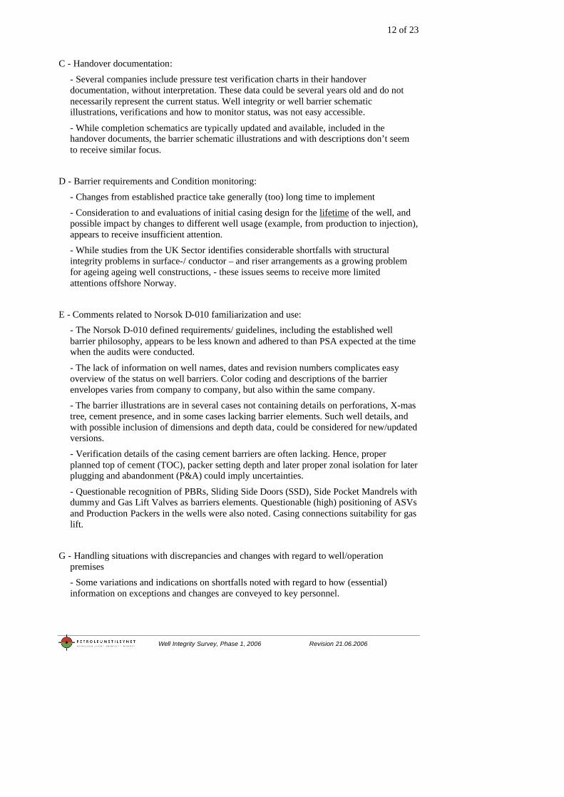
“Active” development wells at NCS per 1.1.2006
– Production: 1539 wells – Injection: 369 wells – Total: 1908 wells
"Active" wells at NCS per 1.1.2006
Injection369 wells
Production1539 wells
INJECTION
PRODUCTION
The figure above shows 369 injection wells and 1539 production wells on the Norwegian Continental Shelf per 1.1.2006. The production wells include water producers, gas producers and oil producers. The injection wells include gas injector, water injector and WAG.
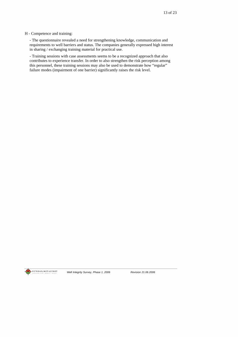
Subsea and platform wells- production and injection per 1.1.2006
528
244
1011
1250
200
400
600
800
1000
1200
Injection Production Injection Production
Platform Subsea
Nu
mb
er o
f w
ells
Serie1
The figure above shows distribution between subsea and platform wells on the NCS
15 of 23
Well Integrity Survey, Phase 1, 2006 Revision 21.06.2006
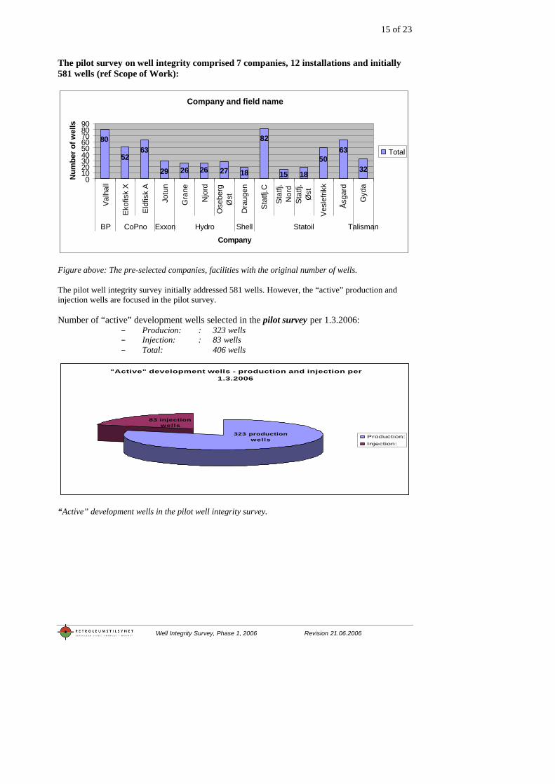
The pilot survey on well integrity comprised 7 companies, 12 installations and initially 581 wells (ref Scope of Work):
Company and field name
32
6350
1815
82
1827262629
6352
80
0102030405060708090
Val
hall
Eko
fisk
X
Eld
fisk
A
Jotu
n
Gra
ne
Njo
rd
Ose
berg
Øst
Dra
ugen
Sta
tfj.C
Sta
tfj.
Nor
dS
tatfj
.Ø
st
Ves
lefri
kk
Åsg
ard
Gyd
a
BP CoPno Exxon Hydro Shell Statoil Talisman
Company
Num
ber o
f wel
ls
Total
Figure above: The pre-selected companies, facilities with the original number of wells. The pilot well integrity survey initially addressed 581 wells. However, the “active” production and injection wells are focused in the pilot survey. Number of “active” development wells selected in the pilot survey per 1.3.2006:
– Producion: : 323 wells – Injection: : 83 wells – Total: 406 wells
"Active" development wells - production and injection per 1.3.2006
323 production wells
83 injection wells
Production:Injection:
“Active” development wells in the pilot well integrity survey.
16 of 23
Well Integrity Survey, Phase 1, 2006 Revision 21.06.2006
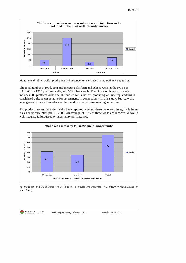
Platform and subsea wells- production and injection wells included in the pilot well integrity survey
74
3251
249
0
50
100
150
200
250
300
Injection Production Injection Production
Platform Subsea
Nu
mb
er
of
wells
Serie1
Platform and subsea wells - production and injection wells included in the well integrity survey. The total number of producing and injecting platform and subsea wells at the NCS per 1.1.2006 are 1255 platform wells, and 653 subsea wells. The pilot well integrity survey includes 300 platform wells and 106 subsea wells that are producing or injecting, and this is considered quite representative for assessments in connection with this study. Subsea wells have generally more limited access for condition monitoring relating to barriers. 406 production- and injection wells have reported whether there were well integrity failures/ issues or uncertainties per 1.3.2006. An average of 18% of these wells are reported to have a well integrity failure/issue or uncertainty per 1.3.2006.
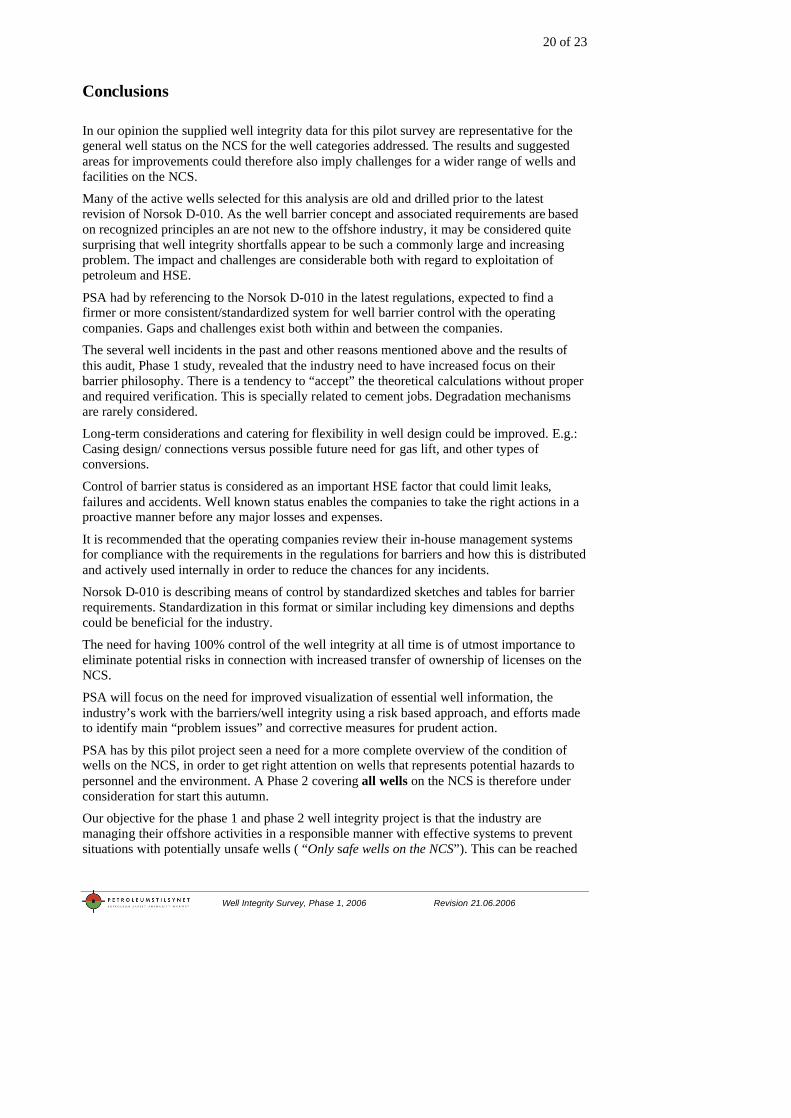
Wells with integrity failure/issue or uncertainty
75
3441
0
10
20
30
40
50
60
70
80
Producer Injector Total
Producer wells , injector wells and total
Nu
mb
er o
f w
ells
Serie1
41 producer and 34 injector wells (in total 75 wells) are reported with integrity failure/issue or uncertainty.

17 of 23
Well Integrity Survey, Phase 1, 2006 Revision 21.06.2006
Well integrity impact
Well integrity impact
1
22
18
8
16
10
0
5
10
15
20
25
A: Shut in B: W orking underconditions
C: Insignificant deviattionfor current operations
Well integrity impact category A, B and C
Num
ber o
f wel
ls
ProducerInjector
Well integrity impact (A, B, C) for producer and injector wells. The figure above illustrates the number of wells with well integrity impact A: well is shut in, B: working under conditions/ exemptions, C: insignificant deviation for current operation for producer and injector wells. Reported wells with integrity failures/issues or uncertainty in category A, B and C:
- Category A, shut in: 28 of 406 wells (7 %) Producer: 18 of the 323 wells Injector: 10 of the 83 wells
- Category B, working under conditions/exemptions: 38 of 406 wells (9 %) Producer: 22 of the 323 wells Injector: 16 of the 83 wells
- Category C, Insignificant deviations for current operations: 9 of 406 wells (2 %) Producer: 8 of the 323 wells
Injector: 1 of the 83 wells Shortfall in ability for extraction is assumed to be roughly 10 % for the well categories above. (The number of wells closed by other reasons than integrity problems are reported to be 37, and causal category E for reservoir technical issues is clearly dominant.)
.

18 of 23
Well Integrity Survey, Phase 1, 2006 Revision 21.06.2006
Age of development wells on the NCS The age of wells are based on the well bore completion year as registered in the NPD database per 1.1.2006.
The figure above illustrates the wells age in years, the number of wells and the relevant operating companies. The figure shows that most of the development wells are 0-12 years old and that the oldest wells on the NCS per 1.1.2006 is 32 years old.
Age of production and injection wells on the NCS per 1.1.2006
3354112195
360
543
242
47367597108420
100
200300
400
500
600
0 to 4 5 to 9 10 to 14 15 to 19 20 to 24 25 to 29 30 to 34
Age in years
Num
ber
of w
ells
ProductionInjection
The figure above illustrates the age in years and the number of producing and injecting wells. Most of the producing and injection wells are 0-14 years old on the NCS per 1.1.2006.
Age of "active" platform and subsea wells on the NCS per 1.1.2006
3761132
217
331320
157
1653126
331
127
050
100150200250300350
0 to 4 5 to 9 10 to 14 15 to 19 20 to 24 25 to 29 30 to 34
Age in years
Num
ber
of w
ells
PlatformSubsea
Age of development wells sorted by the operating companies per.1.1.2006
0
50
100
150
200
250
0 1 2 3 4 5 6 7 8 9 10 11 12 13 14 15 16 17 18 19 20 21 22 23 24 25 26 27 28 29 30 31 32
Age in Years
Number of wells
TOTALTALISMANSTATOIL SHELLSAGA PHILLIPSPERTRAMOBIL HYDROESSOELFCONPHIL CONOCOBP AMOCO

19 of 23
Well Integrity Survey, Phase 1, 2006 Revision 21.06.2006
The figure illustrates the age in years and the number of “active” platform and subsea wells. “Active” wells in this study means producing and injecting wells. Most of the platform and the subsea wells are 0-14 years old. Age of the wells in the pilot well integrity survey
Age of the pre-selected development wells in the well integrity survey and the companies
0
10
20
30
40
50
60
0 1 2 3 4 5 6 7 8 9 10 11 12 13 14 15 16 17 18 19 20 21 22 23 24 26 27 28Age in years
Num
ber
of w
ells
TalismanStatoilShellHydroExxonMobilConocoPhillipsBP
The figure above indicates that most of the development wells are 0-12 years old in the pilot well integrity survey. The oldest well in the pilot well integrity survey is 28 years old.
Pilot well integrity survey – age of wells and well integrity failure/issue or uncertainty.
Age of wells with well integrity failure/issue or uncertainty per 1.3.2006
216
16
26
24
0
5
10
15
20
25
30
0 to 4 5 to 9 10 to 14 15 to 19 20 to 24 25 to 29
Age in years
Nu
mb
er
of
wells
Serie1
The figure above illustrates the age of the wells with well integrity failures/issues or uncertainty. 75 wells of the 406 wells focused in this study with integrity problems. The figure can be seen together with previous distribution on well age, and will illustrate that many of the well integrity problems are associated with wells from the early 1990`s. A peak for integrity impairment intensity is identified from 10-14 years ago The production- and injection wells from the early 1990’s have averagely twice as high impairment intensity as for the older wells.
20 of 23
Well Integrity Survey, Phase 1, 2006 Revision 21.06.2006
Conclusions
In our opinion the supplied well integrity data for this pilot survey are representative for the general well status on the NCS for the well categories addressed. The results and suggested areas for improvements could therefore also imply challenges for a wider range of wells and facilities on the NCS.
Many of the active wells selected for this analysis are old and drilled prior to the latest revision of Norsok D-010. As the well barrier concept and associated requirements are based on recognized principles an are not new to the offshore industry, it may be considered quite surprising that well integrity shortfalls appear to be such a commonly large and increasing problem. The impact and challenges are considerable both with regard to exploitation of petroleum and HSE.
PSA had by referencing to the Norsok D-010 in the latest regulations, expected to find a firmer or more consistent/standardized system for well barrier control with the operating companies. Gaps and challenges exist both within and between the companies. The several well incidents in the past and other reasons mentioned above and the results of this audit, Phase 1 study, revealed that the industry need to have increased focus on their barrier philosophy. There is a tendency to “accept” the theoretical calculations without proper and required verification. This is specially related to cement jobs. Degradation mechanisms are rarely considered.
Long-term considerations and catering for flexibility in well design could be improved. E.g.: Casing design/ connections versus possible future need for gas lift, and other types of conversions.
Control of barrier status is considered as an important HSE factor that could limit leaks, failures and accidents. Well known status enables the companies to take the right actions in a proactive manner before any major losses and expenses.
It is recommended that the operating companies review their in-house management systems for compliance with the requirements in the regulations for barriers and how this is distributed and actively used internally in order to reduce the chances for any incidents.
Norsok D-010 is describing means of control by standardized sketches and tables for barrier requirements. Standardization in this format or similar including key dimensions and depths could be beneficial for the industry.
The need for having 100% control of the well integrity at all time is of utmost importance to eliminate potential risks in connection with increased transfer of ownership of licenses on the NCS.
PSA will focus on the need for improved visualization of essential well information, the industry’s work with the barriers/well integrity using a risk based approach, and efforts made to identify main “problem issues” and corrective measures for prudent action.
PSA has by this pilot project seen a need for a more complete overview of the condition of wells on the NCS, in order to get right attention on wells that represents potential hazards to personnel and the environment. A Phase 2 covering all wells on the NCS is therefore under consideration for start this autumn.
Our objective for the phase 1 and phase 2 well integrity project is that the industry are managing their offshore activities in a responsible manner with effective systems to prevent situations with potentially unsafe wells ( “Only safe wells on the NCS”). This can be reached
21 of 23
Well Integrity Survey, Phase 1, 2006 Revision 21.06.2006
if the industry work to achieve a total overview and real time condition for all wells on the NCS.
Based on the results from the audits and phase1 project PSA believe that improved focus and work with well integrity and well barriers will provide situation that improves both safety and production on the NCS.
Project phase 2 - Discussion Based on the result of pilot project on well integrity it is PSAs view that a more comprehensive study with a strong “problem solving”-approach would be commenced as a well integrity project (Phase 2). The scope of work, execution plans, milestones etc need to be discussed with the operating companies through OLF-Drilling Managers Forum during the autumn of 2006. However, since most of the relevant operating companies have been part of the phase 1 pilot project, they have already demonstrated detailed knowledge and positive attitude to continue improvement efforts. In this context there are also several suggestions indicated in the audit reports, so there should not be reasons to drop momentum at this stage. Based on the audit results the PSA encourage the industry to:
• Improve the present lack of approach and systems of reliability and condition based surveillance for well barriers and well integrity aspects to improve well safety in general on the NCS.
• Provide better visualisation of barriers for both onshore and offshore users to improve the safety level and user friendliness
• Agree on standard ways of visualisation, technical qualification, documentation and abbreviations. Consider making a standard handover package containing basic well engineering data required to give a full overview of the wells barrier envelop situation from spud to abandonment.
• Start the process of updating the Norsok drilling standards to include recent experiences related to well barriers. This should include the qualification process for barrier elements and coming technology.
22 of 23
Well Integrity Survey, Phase 1, 2006 Revision 21.06.2006
Operator: Installation :
Last updated : Revision: Well bore name: Well bore status : Prepare by: Checked by: Type of well: Well details :
Reference documentation: Well integrity problem(s) If any, indicated by _ S
Well barrier elements Table ref.
Initial test & verfication Monitoring Comments (Acceptance criteria/Deviations)
Primary barrier
Secondary barrier
Example illustration
Observation(s):
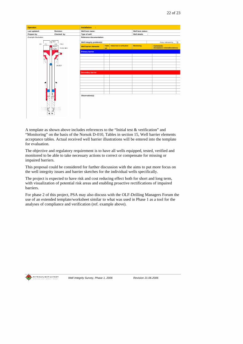
A template as shown above includes references to the “Initial test & verification” and “Monitoring” on the basis of the Norsok D-010, Tables in section 15, Well barrier elements acceptance tables. Actual received well barrier illustrations will be entered into the template for evaluation.
The objective and regulatory requirement is to have all wells equipped, tested, verified and monitored to be able to take necessary actions to correct or compensate for missing or impaired barriers.
This proposal could be considered for further discussion with the aims to put more focus on the well integrity issues and barrier sketches for the individual wells specifically.
The project is expected to have risk and cost reducing effect both for short and long term, with visualization of potential risk areas and enabling proactive rectifications of impaired barriers.
For phase 2 of this project, PSA may also discuss with the OLF-Drilling Managers Forum the use of an extended template/worksheet similar to what was used in Phase 1 as a tool for the analyses of compliance and verification (ref. example above).
23 of 23
Well Integrity Survey, Phase 1, 2006 Revision 21.06.2006
References and abbreviations
Regulations:
http://www.ptil.no/regelverk Norsok D-010, Well integrity in drilling and well operations (Rev. 3 Aug. 2004) http://www.standard.no Company specific answers and documents from the 7 audits -listed in each of the audit reports The Journal of Offshore Technology, May/June 2005: “Structural integrity of North Sea Wells” PSA well integrity seminar 4.5 2006: http://www.ptil.no/Norsk/Helse+miljo+og+sikkerhet/Sikkerhet+og+arbeidsmiljo/6_bronnseminar_presentasjoner.htm Abbreviations: PSA - Petroleum Safety Authority NCS - Norwegian Continental Shelf SD&P - Simultaneous Drilling and Production PBR - Polish Bore Receptacle RKB – Rotary Kelly Bushing (depth reference) P&A - Plug and Abandonment (permanent plugging) NPD - Norwegian Petroleum Directorate


![161104 NET-fin.ppt [Kompatibilitätsmodus]...ISO/TS 16530-2 (Aug 2014-Entwurf): “Part 2: Well integrity for the operational phase”, First edition (Entwurf) (87 Seiten) ISO/TS 16530-1](https://img.pdfslide.tips/doc/110x75/61145a8835ab9e14ee2493d7/161104-net-finppt-kompatibilittsmodus-isots-16530-2-aug-2014-entwurf.jpg)