Embed Size (px)
Citation preview
energies
Article
Research on a Household Dual Heat Source HeatPump Water Heater with Preheater Based onASPEN PLUSXiang Gou *, Yang Fu, Imran Ali Shah, Yamei Li, Guoyou Xu, Yue Yang, Enyu Wang,Liansheng Liu and Jinxiang Wu
School of Energy and Environmental Engineering, Hebei University of Technology, 5340# Xiping Road,Shuangkou Town, Beichen District, Tianjin 300401, China; [email protected] (Y.F.);[email protected] (I.A.S.); [email protected] (Y.L.); [email protected] (G.X.);[email protected] (Y.Y.); [email protected] (E.W.); [email protected] (L.L.);[email protected] (J.W.)* Correspondence: [email protected]; Tel.: +86-22-6043-5781
Academic Editors: Samuel Gendebien and Vincent LemortReceived: 6 October 2016; Accepted: 25 November 2016; Published: 3 December 2016
Abstract: This article proposes a dual heat source heat pump bathroom unit with preheater whichis feasible for a single family. The system effectively integrates the air source heat pump (ASHP)and wastewater source heat pump (WSHP) technologies, and incorporates a preheater to recovershower wastewater heat and thus improve the total coefficient of performance (COP) of the system,and it has no electric auxiliary heating device, which is favorable to improve the security of thesystem operation. The process simulation software ASPEN PLUS, widely used in the design andoptimization of thermodynamic systems, was used to simulate various cases of system use and toanalyze the impact of the preheater on the system. The average COP value of a system with preheateris 6.588 and without preheater it is 4.677. Based on the optimization and analysis, under the standardconditions of air at 25 ◦C, relative humidity of 70%, wastewater at 35 ◦C, wastewater flow rate of0.07 kg/s, tap water at 15 ◦C, and condenser outlet water temperature at 50 ◦C, the theoretical COPof the system can reach 9.784 at an evaporating temperature of 14.96 ◦C, condensing temperature of48.74 ◦C, and preheated water temperature of 27.19 ◦C.
Keywords: dual heat source; heat pump; household water heater; preheater; ASPEN PLUS; coefficientof performance (COP)
1. Introduction
Along with the increasingly serious environmental pollution and scarce resources, people havepaid more and more attention to energy conservation and emissions reduction [1,2]. A heat pump (HP)can use some amount of external power to move thermal energy from a heat source (air, wastewater,ground, underground water, etc.) to a warmer destination (hot air, hot water, etc.) called a “heat sink”.Various forms of heat pump (HP) technology have been gradually popularized in recent years, such asair source heat pump (ASHP) technology (extracting heat from air), wastewater source heat pump(WSHP) technology (extracting heat from wastewater), ground source heat pump (GSHP) technology(extracting heat from ground) [3] and underground water source heat pump (UWSHP) technology(extracting heat from underground water) [4]. Among all these heat pump technologies, ASHP andWSHP technologies play an important role [5].
ASHP technology is being used by many families nowadays and there also exist a wide range ofapplications in industry. It is also widely used in the areas having warm climates where the evaporatorof an ASHP water heater is generally installed as an outdoor heat exchanger. It absorbs heat from the
Energies 2016, 9, 1026; doi:10.3390/en9121026 www.mdpi.com/journal/energies
Energies 2016, 9, 1026 2 of 16
outdoor atmosphere to heat the cold water used for household and industry. However, if the outdoorenvironmental temperature is less, the system operation becomes neither efficient nor reliable orstable [6,7]. Several scholars have conducted a lot of research to address its disadvantages, and obtainedthe solution in the form of certain advanced techniques such as heat pump systems coupled withejectors and economized vapor injection scroll compressors [8,9], two-stage compression heat pumpsystems [10,11], cascade heat pump systems [12,13], heat pump systems with alternative workingfluids [14–16], heat pump systems using phase change material [17–19] and heat pump systemscoupled with other energy sources [20–23], but these advancements increase system complexity andthe overheads incurred in the system manufacture, operation and control. Therefore, these solutionsare usually not advisable for household heat pump systems.
WSHP research focuses on large scale centralized users, such as communities, hotels and bathcenters. WSHP is better than an ASHP since wastewater is less affected by climate, season andenvironmental temperature. Furthermore, its temperature is relatively stable during runtime and thereliability of the system is improved. However, there also exist the disadvantages of clogging andscaling. Currently, there are a lot of studies engaged in solving these problems, and to some extent,these problems related to WSHPs have been solved. Thus, studies on making WSHP systems usingsmall-sized and domestic shower wastewater are reported [24–26]. Kahraman et al. [27] proposed aWSHP water heater system. They used immersion tanks to design the wastewater source evaporatorand the condenser. The coefficient of performance (COP) of the system rose as the temperature ofwastewater increased, whereby for the heat source temperatures of 20 ◦C, 30 ◦C and 40 ◦C, the COPs ofthe system became 3.36, 3.43 and 3.69, respectively. Besides, as the temperature of the cold water to beheated rose, the condensing pressure increased. At the same time, the evaporating pressure was almostinvariable, thus heating capacity and COP decreased. Wong et al. [28] proposed a shower water heatsource heat pump water heater system for high-rise residential buildings. The condenser of the systemis a directly-heated type. They analyzed the effects of shower running time, shower wastewater flowrate and structure of heat exchangers on the system energy saving effect. The feasibility and the energysaving properties were verified through their experiments. Liu et al. [29] proposed a system basedupon WSHP technology for public shower facilities. The system was based on an absorption heat pumpcycle and a preheater was added. They introduced the components and control process of the system.The economics and energy-saving effect of the system was compared with traditional electric heatpump (TEHP) systems. The COP of the system was 3.26 under the design conditions and the highestCOP of the system recorded during runtime was 5.76. They found that the heat recovery system usinga direct-fired absorption heat pump had lower energy consumption, less pollution, lower operatingcost, and shorter payback period. Chen et al. [30] proposed a heat pump (HP) water heater for bathing,to which shower wastewater was added and could supply hot water in a few minutes. The regeneratorand the wastewater source evaporator were separated. A thermodynamic system comprised ofboth static and dynamic models was developed, and the corresponding numerical simulations wereconducted. The optimal COP of the whole system reached 4.97 as the condensing and evaporatingtemperatures were optimized at 51.50 ◦C and 11.68 ◦C, respectively. The simulation results providedgood guidelines for the further design and optimization of the system. Dong et al. [31] proposeda novel HP water heater assisted with shower drain water designed for a small family. A showerwaste heat extraction device with water preheated loops was designed to improve its performance,but this system was assisted by a single heat source and an electric auxiliary heating device was added.The experimental results revealed that about 70% of energy could be conserved by using this novel HPwater heater, compared with that of the traditional electric water heater.
Scholars have conducted relatively less research on the combination of air source and wastewatersource heat pump technology. The objects of their studies were focused on large centralized sites,and some of them were assisted with other energy sources, such as solar energy and ground heatsources. Chen et al. [32] proposed an AWDSHP water heater for heat recovery. The heat pumpsystem could heat water by using a single air source, a single water source, or air-water dual sources.
Energies 2016, 9, 1026 3 of 16
The results of analysis and experiments showed that COP of the device can reach up to 4–5.5 in winter,twice as much as of an air source heat pump (ASHP) water heater. The utilization of waste heat in theproposed system was more than that in the system comprised only of wastewater as heat or preheatingsource. The energy saving effect of the new system was obvious. Zhang et al. [33,34] proposed anair-water dual source compound heat exchanger in a solar-air dual source compound heat pump(SADSCHP) system. The air-water dual source compound heat exchanger was used as the evaporatorof the heat pump system, and it was the key component. The evaporator made three kinds of workingfluid exchange heat synchronously. The mathematical model of the solar-air dual source compoundheat pump (SADSCHP) system was established. The mathematical simulation method has been usedto study the effect of the structure parameters of air-water dual source compound heat exchanger onthe energy saving efficiency of the SADSCHP system, and the optimization scheme of the structureparameters under the simulating condition was determined.
Air source and wastewater source heat pump technologies have been widely studied. However,the organic combination of both technologies lacks meaningful exploration. Therefore, this articleproposes a dual heat source heat pump bathroom unit with preheater, which is suitable for a family touse, and the process simulation software ASPEN PLUS was used to simulate and analyze the system.
2. Characteristics of the System
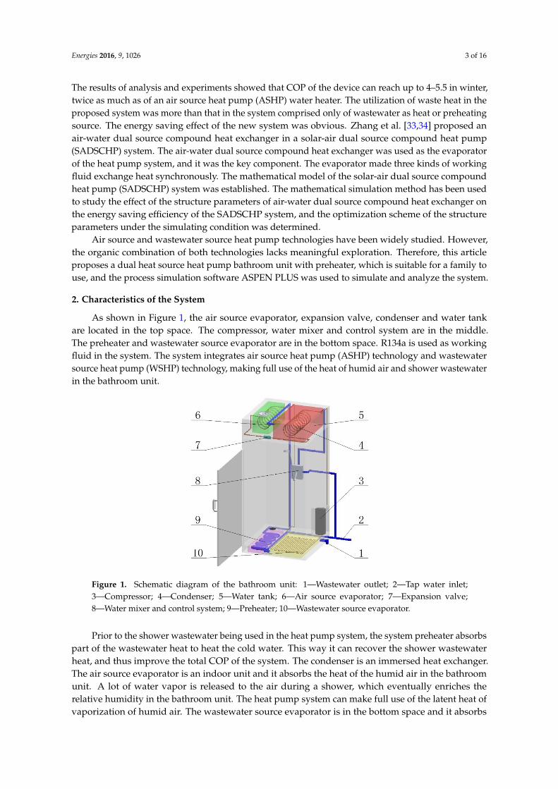
As shown in Figure 1, the air source evaporator, expansion valve, condenser and water tankare located in the top space. The compressor, water mixer and control system are in the middle.The preheater and wastewater source evaporator are in the bottom space. R134a is used as workingfluid in the system. The system integrates air source heat pump (ASHP) technology and wastewatersource heat pump (WSHP) technology, making full use of the heat of humid air and shower wastewaterin the bathroom unit.
Energies 2016, 9, 1026 3 of 16
water source, or air-water dual sources. The results of analysis and experiments showed that COP of the device can reach up to 4–5.5 in winter, twice as much as of an air source heat pump (ASHP) water heater. The utilization of waste heat in the proposed system was more than that in the system comprised only of wastewater as heat or preheating source. The energy saving effect of the new system was obvious. Zhang et al. [33,34] proposed an air-water dual source compound heat exchanger in a solar-air dual source compound heat pump (SADSCHP) system. The air-water dual source compound heat exchanger was used as the evaporator of the heat pump system, and it was the key component. The evaporator made three kinds of working fluid exchange heat synchronously. The mathematical model of the solar-air dual source compound heat pump (SADSCHP) system was established. The mathematical simulation method has been used to study the effect of the structure parameters of air-water dual source compound heat exchanger on the energy saving efficiency of the SADSCHP system, and the optimization scheme of the structure parameters under the simulating condition was determined.
Air source and wastewater source heat pump technologies have been widely studied. However, the organic combination of both technologies lacks meaningful exploration. Therefore, this article proposes a dual heat source heat pump bathroom unit with preheater, which is suitable for a family to use, and the process simulation software ASPEN PLUS was used to simulate and analyze the system.
2. Characteristics of the System
As shown in Figure 1, the air source evaporator, expansion valve, condenser and water tank are located in the top space. The compressor, water mixer and control system are in the middle. The preheater and wastewater source evaporator are in the bottom space. R134a is used as working fluid in the system. The system integrates air source heat pump (ASHP) technology and wastewater source heat pump (WSHP) technology, making full use of the heat of humid air and shower wastewater in the bathroom unit.
Figure 1. Schematic diagram of the bathroom unit: 1—Wastewater outlet; 2—Tap water inlet; 3—Compressor; 4—Condenser; 5—Water tank; 6—Air source evaporator; 7—Expansion valve; 8—Water mixer and control system; 9—Preheater; 10—Wastewater source evaporator.
Prior to the shower wastewater being used in the heat pump system, the system preheater absorbs part of the wastewater heat to heat the cold water. This way it can recover the shower wastewater heat, and thus improve the total COP of the system. The condenser is an immersed heat exchanger. The air source evaporator is an indoor unit and it absorbs the heat of the humid air in the bathroom unit. A lot of water vapor is released to the air during a shower, which eventually enriches the relative humidity in the bathroom unit. The heat pump system can make full use of the latent heat of vaporization of humid air. The wastewater source evaporator is in the bottom space and it
Figure 1. Schematic diagram of the bathroom unit: 1—Wastewater outlet; 2—Tap water inlet;3—Compressor; 4—Condenser; 5—Water tank; 6—Air source evaporator; 7—Expansion valve;8—Water mixer and control system; 9—Preheater; 10—Wastewater source evaporator.
Prior to the shower wastewater being used in the heat pump system, the system preheater absorbspart of the wastewater heat to heat the cold water. This way it can recover the shower wastewaterheat, and thus improve the total COP of the system. The condenser is an immersed heat exchanger.The air source evaporator is an indoor unit and it absorbs the heat of the humid air in the bathroomunit. A lot of water vapor is released to the air during a shower, which eventually enriches therelative humidity in the bathroom unit. The heat pump system can make full use of the latent heat ofvaporization of humid air. The wastewater source evaporator is in the bottom space and it absorbs
Energies 2016, 9, 1026 4 of 16
the heat of shower wastewater. The system can avoid the effects of the climate and environmentaltemperature. Furthermore, it does not need an electric auxiliary heating device and completely realizesthe separation of water and electricity. This method improves the reliability and security of the systemoperation and reduces the system manufacturing and operation cost. When the system starts up forthe first time or in the process of heat preservation after taking a shower, the automatic control systemturns the wastewater source evaporator off and turns the air source evaporator on to heat water tospecified temperature for taking a shower. In the process of bathing, the air source evaporator andwastewater source evaporator take part simultaneously in providing hot water continuously. ASPENPLUS has been used to simulate the operation parameters under different working conditions in theshower process of the system, and the impact of the preheater on the total COP value of the system isanalyzed. Comparisons of the system energy saving effect under different working conditions withand without preheater are presented.
3. Establishment of the Simulation Process
ASPEN PLUS is a large scale general process simulation software with a huge physical propertydatabase mostly used in the chemical industry field. This software has an integrated structure andincludes process-related unit operation modules besides components, properties and state equations.Every segment of heat pump system is designated the corresponding module. The field of chemicalindustry which ASPEN PLUS is concentrating on and the field of heat pump and refrigeration havecommon theoretical bases on the fundamental equation of states, transfer equation and constitutiveequation of matters [35–37].
3.1. The State and Property of the Matter in the Simulation Process
During simulation with ASPEN PLUS, the physical property methods adopted have been selectedaccording to their corresponding matters such as for the R134a working fluid, the Peng Robinson (PR)property method was chosen. Similarly, IDEAL and STEAM-TA property methods were engaged fordry air contained in humid air and pure water & steam, respectively. These property methods aredescribed below.
3.1.1. The Peng-Robinson Property Method
Peng Robinson (PR) equation is a dual parameter equation as well as a modified version of theRedlich-Kwang (RK) equation. It was proposed by Peng-Robinson in 1976 [38]. However, there aresome shortcomings in RK equation that are not resolved by using the PR equation; such as the fact thatit fails to generate satisfactory density values for a liquid even if the calculated vapor densities weregenerally accepted. The empirical form of the PR equation is:
p =RT
v− b− a
v (v + b) + b (v− b)(1)
in which, b = 0.07780 RTcpc
; a = a (T c)α; a (Tc) = 0.45724 R2T2re
pc; α0.5 = 1 + ak(1− T0.5
re ); ak = 0.37464 +
1.54226ω− 0.26992ω2; Tre = T/Tc. The PR equation can be rewritten as:
Z3 − (1− B) Z2 +(
A− 3B2 − 2B)
Z−(
AB− B2 − B3)= 0 (2)
in which, A =ap
R2T2 ; B =bpRT ; Z =
pvRT .
The PR equation can be used in both the gaseous and liquid phases. The degree of accuracywhen calculating the volume of gaseous phase with the PR equation is equal to that of theRedlich-Kwang-Soave (RKS) equation [39], but it is higher than the RKS equation when calculating thevolume of a liquid phase and criticality. The PR equation offers the same simplicity as the RKS oneand since both equations predict enthalpy values and vapor densities with reasonable accuracy, based
Energies 2016, 9, 1026 5 of 16
on that fact, PR is not an exception but can only justify with simplicity and similar accuracy. Neither ofthe equations are suitable for quantum gases or strongly polar gases.
3.1.2. The IDEAL Property Method
The ideal gas law (ideal gas state equation) combines Boyle’s law and Gay-Lussac’s law. Whenusing the IDEAL property method to simulate a gas, it seems that the gas is composed of pointsubstances that have no interaction with each other. The ideal gas law is used as the reference state forstate equations, and can also be used to simulate gaseous mixtures (where the gaseous phases have nointeraction with each other) at low pressure. The equation is as below:
p =RTVm
(3)
3.1.3. STEAM-TA Property Method
The STEAM-TA property method uses the 1967 ASME steam table [40] correlations to calculatethermodynamic properties and uses International Association for Properties of Steam (IAPS)correlations to estimate the transfer properties. The ASME steam tables are based on the IFCformulations for the thermodynamic properties, which contain 328 pages with 19 tables and 22 chartsand figures. The temperature range used in this property method is limited between 237.15 K and1073 K while the highest pressure is up to 1000 bar. For process calculations, the model’s accuracyis enough. However, the STEAM-TA method is made up of different correlations covering differentregions of the P-T space and such correlations do not provide continuity at the boundaries, thus it mayhave problems in converging and predicting wrong trends.
3.1.4. The Fluid Transfer Modules
The modules for fluid transfer in the system within ASPEN PLUS should satisfy theequations below:
Mass conservation equation:Mprev,out = Mnext,in (4)
Energy conservation equation:hprev,out = hnext,in (5)
Momentum conservation equation:
Sprev,out = Snext,in (6)
The fluid heat flow in each module within ASPEN PLUS should satisfy the equations below:For cooler module:
HeatFlowin −Dutycooler = HeatFlowout (7)
For heat exchanger module:
Mcold [hout − hin]cold −Qleak = Mhot [hin − hout]hot −Qloss (8)
Qheatx = UA∆TLMF (9)
For mixer module:
chotMhot (Thot,in − Thot,out) = ccoldMcold (Tcold,out − Tcold,in) (10)
Thot,out = Tcold,out (11)
Energies 2016, 9, 1026 6 of 16
For compressor module:W = Mr (hdis − hsuc) (12)
For valve module:hv,out = hv,in (13)
For the whole heat pump system:
Qcond = Qair,evap + Qwastewater,evap + W (14)
Qtotal = Qcond + Qpreheater = Qair,evap + Qwastewater,evap + W + Qpreheater (15)
COP =Qtotal
W(16)
3.2. Establishment of the Simulation Process
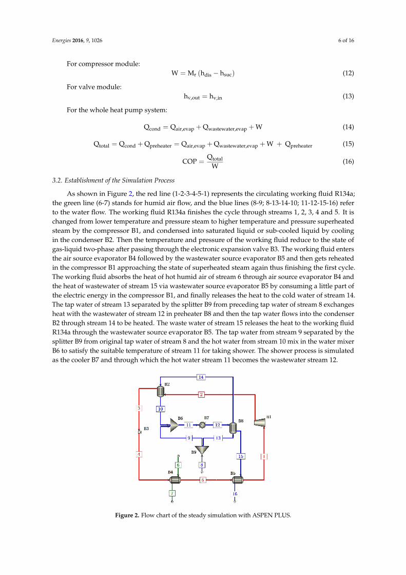
As shown in Figure 2, the red line (1-2-3-4-5-1) represents the circulating working fluid R134a;the green line (6-7) stands for humid air flow, and the blue lines (8-9; 8-13-14-10; 11-12-15-16) referto the water flow. The working fluid R134a finishes the cycle through streams 1, 2, 3, 4 and 5. It ischanged from lower temperature and pressure steam to higher temperature and pressure superheatedsteam by the compressor B1, and condensed into saturated liquid or sub-cooled liquid by coolingin the condenser B2. Then the temperature and pressure of the working fluid reduce to the state ofgas-liquid two-phase after passing through the electronic expansion valve B3. The working fluid entersthe air source evaporator B4 followed by the wastewater source evaporator B5 and then gets reheatedin the compressor B1 approaching the state of superheated steam again thus finishing the first cycle.The working fluid absorbs the heat of hot humid air of stream 6 through air source evaporator B4 andthe heat of wastewater of stream 15 via wastewater source evaporator B5 by consuming a little part ofthe electric energy in the compressor B1, and finally releases the heat to the cold water of stream 14.The tap water of stream 13 separated by the splitter B9 from preceding tap water of stream 8 exchangesheat with the wastewater of stream 12 in preheater B8 and then the tap water flows into the condenserB2 through stream 14 to be heated. The waste water of stream 15 releases the heat to the working fluidR134a through the wastewater source evaporator B5. The tap water from stream 9 separated by thesplitter B9 from original tap water of stream 8 and the hot water from stream 10 mix in the water mixerB6 to satisfy the suitable temperature of stream 11 for taking shower. The shower process is simulatedas the cooler B7 and through which the hot water stream 11 becomes the wastewater stream 12.
Energies 2016, 9, 1026 6 of 16
hv,out = hv,in (13)
For the whole heat pump system: Qcond=Qair,evap +Qwastewater,evap +W (14) Qtotal=Qcond+Qpreheater=Qair,evap +Qwastewater,evap +W+Qpreheater (15)
COP=QtotalW (16)
3.2. Establishment of the Simulation Process
As shown in Figure 2, the red line (1-2-3-4-5-1) represents the circulating working fluid R134a; the green line (6-7) stands for humid air flow, and the blue lines (8-9; 8-13-14-10; 11-12-15-16) refer to the water flow. The working fluid R134a finishes the cycle through streams 1, 2, 3, 4 and 5. It is changed from lower temperature and pressure steam to higher temperature and pressure superheated steam by the compressor B1, and condensed into saturated liquid or sub-cooled liquid by cooling in the condenser B2. Then the temperature and pressure of the working fluid reduce to the state of gas-liquid two-phase after passing through the electronic expansion valve B3. The working fluid enters the air source evaporator B4 followed by the wastewater source evaporator B5 and then gets reheated in the compressor B1 approaching the state of superheated steam again thus finishing the first cycle. The working fluid absorbs the heat of hot humid air of stream 6 through air source evaporator B4 and the heat of wastewater of stream 15 via wastewater source evaporator B5 by consuming a little part of the electric energy in the compressor B1, and finally releases the heat to the cold water of stream 14. The tap water of stream 13 separated by the splitter B9 from preceding tap water of stream 8 exchanges heat with the wastewater of stream 12 in preheater B8 and then the tap water flows into the condenser B2 through stream 14 to be heated. The waste water of stream 15 releases the heat to the working fluid R134a through the wastewater source evaporator B5. The tap water from stream 9 separated by the splitter B9 from original tap water of stream 8 and the hot water from stream 10 mix in the water mixer B6 to satisfy the suitable temperature of stream 11 for taking shower. The shower process is simulated as the cooler B7 and through which the hot water stream 11 becomes the wastewater stream 12.
Figure 2. Flow chart of the steady simulation with ASPEN PLUS.
3.3. Cases of the Steady State Simulation with ASPEN PLUS
Figure 2. Flow chart of the steady simulation with ASPEN PLUS.
Energies 2016, 9, 1026 7 of 16
3.3. Cases of the Steady State Simulation with ASPEN PLUS
ASPEN PLUS was used to simulate the steady state of the system through varying parametersunder different working conditions. Supposing that the flow rate of the air remains unchanged due tothe ventilation needed for safety during the shower and the heat loss of the system is ignored, the steadystate simulation of the system is performed according to the four different working conditions shownin Table 1. The working fluid R134a is under the conditions of evaporating temperature at 5 ◦C andcondensing temperature at 50 ◦C. Air temperature remains at 25 ◦C and its relative humidity is 70%.
Table 1. Different working conditions of the steady simulation.
Case WastewaterTemperature (◦C)
Tap WaterTemperature (◦C)
Wastewater MassFlow (kg/s)
Preheated WaterTemperature (◦C)
1 30–40 15 0.07 252 35 10–20 0.07 20–303 35 15 0.06–0.08 254 35 15 0.07 15–25
Case 1: Wastewater temperature of the preheater B8 inlet is adjusted by changing the temperatureof stream 12. The system variation is obtained while the other three parameters remain unchanged.
Case 2: Tap water temperature is adjusted by varying the temperature of stream 8 withinthe temperature range of 10–20 ◦C and preheated water temperature is changed from 20 to 30 ◦C.The system change is observed while the other two parameters remain unchanged.
Case 3: Wastewater mass flow is adjusted by changing the mass flow of stream 11. It is themass flow of the hot water used during taking shower. The system alteration is recorded as the otherthree parameters remain unchanged.
Case 4: Preheated water temperature is adjusted by altering the temperature of stream 14.The system variation is observed while the other three parameters remain constant.
4. Simulation Results and Analyses
4.1. Influence of Inlet Wastewater Temperature on the System
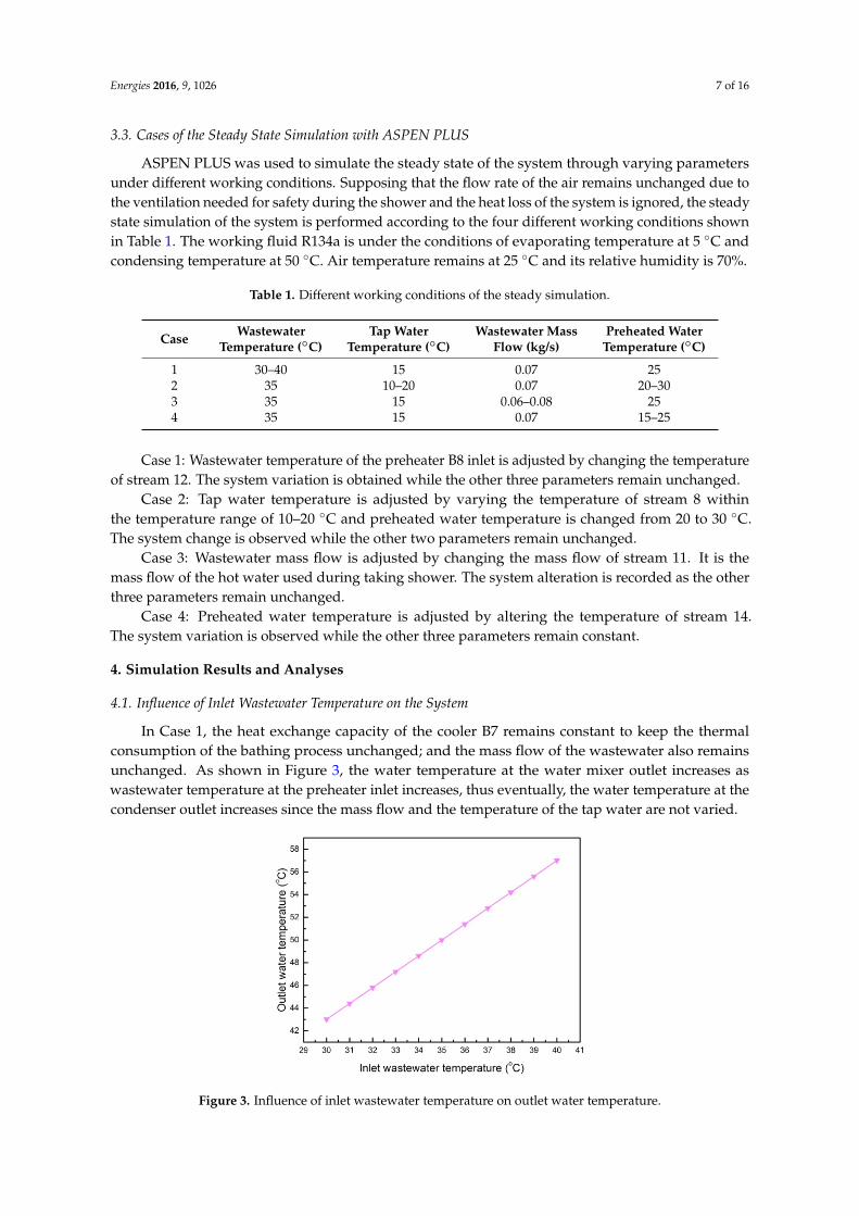
In Case 1, the heat exchange capacity of the cooler B7 remains constant to keep the thermalconsumption of the bathing process unchanged; and the mass flow of the wastewater also remainsunchanged. As shown in Figure 3, the water temperature at the water mixer outlet increases aswastewater temperature at the preheater inlet increases, thus eventually, the water temperature at thecondenser outlet increases since the mass flow and the temperature of the tap water are not varied.
Energies 2016, 9, 1026 7 of 16
ASPEN PLUS was used to simulate the steady state of the system through varying parameters under different working conditions. Supposing that the flow rate of the air remains unchanged due to the ventilation needed for safety during the shower and the heat loss of the system is ignored, the steady state simulation of the system is performed according to the four different working conditions shown in Table 1. The working fluid R134a is under the conditions of evaporating temperature at 5 °C and condensing temperature at 50 °C. Air temperature remains at 25 °C and its relative humidity is 70%.
Table 1. Different working conditions of the steady simulation.
Case Wastewater Temperature (°C)
Tap WaterTemperature (°C)
Wastewater Mass Flow (kg/s)
Preheated Water Temperature (°C)
1 30–40 15 0.07 25 2 35 10–20 0.07 20–30 3 35 15 0.06–0.08 25 4 35 15 0.07 15–25
Case 1: Wastewater temperature of the preheater B8 inlet is adjusted by changing the temperature of stream 12. The system variation is obtained while the other three parameters remain unchanged.
Case 2: Tap water temperature is adjusted by varying the temperature of stream 8 within the temperature range of 10–20 °C and preheated water temperature is changed from 20 to 30 °C. The system change is observed while the other two parameters remain unchanged.
Case 3: Wastewater mass flow is adjusted by changing the mass flow of stream 11. It is the mass flow of the hot water used during taking shower. The system alteration is recorded as the other three parameters remain unchanged.
Case 4: Preheated water temperature is adjusted by altering the temperature of stream 14. The system variation is observed while the other three parameters remain constant.
4. Simulation Results and Analyses
4.1. Influence of Inlet Wastewater Temperature on the System
In Case 1, the heat exchange capacity of the cooler B7 remains constant to keep the thermal consumption of the bathing process unchanged; and the mass flow of the wastewater also remains unchanged. As shown in Figure 3, the water temperature at the water mixer outlet increases as wastewater temperature at the preheater inlet increases, thus eventually, the water temperature at the condenser outlet increases since the mass flow and the temperature of the tap water are not varied.
Figure 3. Influence of inlet wastewater temperature on outlet water temperature. Figure 3. Influence of inlet wastewater temperature on outlet water temperature.
Energies 2016, 9, 1026 8 of 16
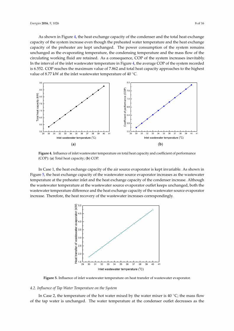
As shown in Figure 4, the heat exchange capacity of the condenser and the total heat exchangecapacity of the system increase even though the preheated water temperature and the heat exchangecapacity of the preheater are kept unchanged. The power consumption of the system remainsunchanged as the evaporating temperature, the condensing temperature and the mass flow of thecirculating working fluid are retained. As a consequence, COP of the system increases inevitably.In the interval of the inlet wastewater temperature in Figure 4, the average COP of the system recordedis 6.552. COP reaches the maximum value of 7.862 and total heat capacity approaches to the highestvalue of 8.77 kW at the inlet wastewater temperature of 40 ◦C.
Energies 2016, 9, 1026 8 of 16
As shown in Figure 4, the heat exchange capacity of the condenser and the total heat exchange capacity of the system increase even though the preheated water temperature and the heat exchange capacity of the preheater are kept unchanged. The power consumption of the system remains unchanged as the evaporating temperature, the condensing temperature and the mass flow of the circulating working fluid are retained. As a consequence, COP of the system increases inevitably. In the interval of the inlet wastewater temperature in Figure 4, the average COP of the system recorded is 6.552. COP reaches the maximum value of 7.862 and total heat capacity approaches to the highest value of 8.77 kW at the inlet wastewater temperature of 40 °C.
(a) (b)
Figure 4. Influence of inlet wastewater temperature on total heat capacity and coefficient of performance (COP): (a) Total heat capacity; (b) COP.
In Case 1, the heat exchange capacity of the air source evaporator is kept invariable. As shown in Figure 5, the heat exchange capacity of the wastewater source evaporator increases as the wastewater temperature at the preheater inlet and the heat exchange capacity of the condenser increase. Although the wastewater temperature at the wastewater source evaporator outlet keeps unchanged, both the wastewater temperature difference and the heat exchange capacity of the wastewater source evaporator increase. Therefore, the heat recovery of the wastewater increases correspondingly.
Figure 5. Influence of inlet wastewater temperature on heat transfer of wastewater evaporator.
4.2. Influence of Tap Water Temperature on the System
In Case 2, the temperature of the hot water mixed by the water mixer is 40 °C; the mass flow of the tap water is unchanged. The water temperature at the condenser outlet decreases as the temperature of the tap water increases. The preheated water temperature also increases to make the
Figure 4. Influence of inlet wastewater temperature on total heat capacity and coefficient of performance(COP): (a) Total heat capacity; (b) COP.
In Case 1, the heat exchange capacity of the air source evaporator is kept invariable. As shown inFigure 5, the heat exchange capacity of the wastewater source evaporator increases as the wastewatertemperature at the preheater inlet and the heat exchange capacity of the condenser increase. Althoughthe wastewater temperature at the wastewater source evaporator outlet keeps unchanged, both thewastewater temperature difference and the heat exchange capacity of the wastewater source evaporatorincrease. Therefore, the heat recovery of the wastewater increases correspondingly.
Energies 2016, 9, 1026 8 of 16
As shown in Figure 4, the heat exchange capacity of the condenser and the total heat exchange capacity of the system increase even though the preheated water temperature and the heat exchange capacity of the preheater are kept unchanged. The power consumption of the system remains unchanged as the evaporating temperature, the condensing temperature and the mass flow of the circulating working fluid are retained. As a consequence, COP of the system increases inevitably. In the interval of the inlet wastewater temperature in Figure 4, the average COP of the system recorded is 6.552. COP reaches the maximum value of 7.862 and total heat capacity approaches to the highest value of 8.77 kW at the inlet wastewater temperature of 40 °C.
(a) (b)
Figure 4. Influence of inlet wastewater temperature on total heat capacity and coefficient of performance (COP): (a) Total heat capacity; (b) COP.
In Case 1, the heat exchange capacity of the air source evaporator is kept invariable. As shown in Figure 5, the heat exchange capacity of the wastewater source evaporator increases as the wastewater temperature at the preheater inlet and the heat exchange capacity of the condenser increase. Although the wastewater temperature at the wastewater source evaporator outlet keeps unchanged, both the wastewater temperature difference and the heat exchange capacity of the wastewater source evaporator increase. Therefore, the heat recovery of the wastewater increases correspondingly.
Figure 5. Influence of inlet wastewater temperature on heat transfer of wastewater evaporator.
4.2. Influence of Tap Water Temperature on the System
In Case 2, the temperature of the hot water mixed by the water mixer is 40 °C; the mass flow of the tap water is unchanged. The water temperature at the condenser outlet decreases as the temperature of the tap water increases. The preheated water temperature also increases to make the
Figure 5. Influence of inlet wastewater temperature on heat transfer of wastewater evaporator.
4.2. Influence of Tap Water Temperature on the System
In Case 2, the temperature of the hot water mixed by the water mixer is 40 ◦C; the mass flowof the tap water is unchanged. The water temperature at the condenser outlet decreases as the
Energies 2016, 9, 1026 9 of 16
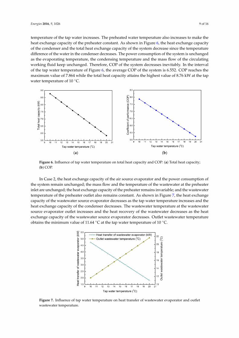
temperature of the tap water increases. The preheated water temperature also increases to make theheat exchange capacity of the preheater constant. As shown in Figure 6, the heat exchange capacityof the condenser and the total heat exchange capacity of the system decrease since the temperaturedifference of the water in the condenser decreases. The power consumption of the system is unchangedas the evaporating temperature, the condensing temperature and the mass flow of the circulatingworking fluid keep unchanged. Therefore, COP of the system decreases inevitably. In the intervalof the tap water temperature of Figure 6, the average COP of the system is 6.552. COP reaches themaximum value of 7.864 while the total heat capacity attains the highest value of 8.76 kW at the tapwater temperature of 10 ◦C.
Energies 2016, 9, 1026 9 of 16
heat exchange capacity of the preheater constant. As shown in Figure 6, the heat exchange capacity of the condenser and the total heat exchange capacity of the system decrease since the temperature difference of the water in the condenser decreases. The power consumption of the system is unchanged as the evaporating temperature, the condensing temperature and the mass flow of the circulating working fluid keep unchanged. Therefore, COP of the system decreases inevitably. In the interval of the tap water temperature of Figure 6, the average COP of the system is 6.552. COP reaches the maximum value of 7.864 while the total heat capacity attains the highest value of 8.76 kW at the tap water temperature of 10 °C.
(a) (b)
Figure 6. Influence of tap water temperature on total heat capacity and COP: (a) Total heat capacity; (b) COP.
In Case 2, the heat exchange capacity of the air source evaporator and the power consumption of the system remain unchanged; the mass flow and the temperature of the wastewater at the preheater inlet are unchanged; the heat exchange capacity of the preheater remains invariable; and the wastewater temperature of the preheater outlet also remains constant. As shown in Figure 7, the heat exchange capacity of the wastewater source evaporator decreases as the tap water temperature increases and the heat exchange capacity of the condenser decreases. The wastewater temperature at the wastewater source evaporator outlet increases and the heat recovery of the wastewater decreases as the heat exchange capacity of the wastewater source evaporator decreases. Outlet wastewater temperature obtains the minimum value of 11.64 °C at the tap water temperature of 10 °C.
Figure 7. Influence of tap water temperature on heat transfer of wastewater evaporator and outlet wastewater temperature.
4.3. Influence of Wastewater Flow on the System
Figure 6. Influence of tap water temperature on total heat capacity and COP: (a) Total heat capacity;(b) COP.
In Case 2, the heat exchange capacity of the air source evaporator and the power consumption ofthe system remain unchanged; the mass flow and the temperature of the wastewater at the preheaterinlet are unchanged; the heat exchange capacity of the preheater remains invariable; and the wastewatertemperature of the preheater outlet also remains constant. As shown in Figure 7, the heat exchangecapacity of the wastewater source evaporator decreases as the tap water temperature increases and theheat exchange capacity of the condenser decreases. The wastewater temperature at the wastewatersource evaporator outlet increases and the heat recovery of the wastewater decreases as the heatexchange capacity of the wastewater source evaporator decreases. Outlet wastewater temperatureobtains the minimum value of 11.64 ◦C at the tap water temperature of 10 ◦C.
Energies 2016, 9, 1026 9 of 16
heat exchange capacity of the preheater constant. As shown in Figure 6, the heat exchange capacity of the condenser and the total heat exchange capacity of the system decrease since the temperature difference of the water in the condenser decreases. The power consumption of the system is unchanged as the evaporating temperature, the condensing temperature and the mass flow of the circulating working fluid keep unchanged. Therefore, COP of the system decreases inevitably. In the interval of the tap water temperature of Figure 6, the average COP of the system is 6.552. COP reaches the maximum value of 7.864 while the total heat capacity attains the highest value of 8.76 kW at the tap water temperature of 10 °C.
(a) (b)
Figure 6. Influence of tap water temperature on total heat capacity and COP: (a) Total heat capacity; (b) COP.
In Case 2, the heat exchange capacity of the air source evaporator and the power consumption of the system remain unchanged; the mass flow and the temperature of the wastewater at the preheater inlet are unchanged; the heat exchange capacity of the preheater remains invariable; and the wastewater temperature of the preheater outlet also remains constant. As shown in Figure 7, the heat exchange capacity of the wastewater source evaporator decreases as the tap water temperature increases and the heat exchange capacity of the condenser decreases. The wastewater temperature at the wastewater source evaporator outlet increases and the heat recovery of the wastewater decreases as the heat exchange capacity of the wastewater source evaporator decreases. Outlet wastewater temperature obtains the minimum value of 11.64 °C at the tap water temperature of 10 °C.
Figure 7. Influence of tap water temperature on heat transfer of wastewater evaporator and outlet wastewater temperature.
4.3. Influence of Wastewater Flow on the System
Figure 7. Influence of tap water temperature on heat transfer of wastewater evaporator and outletwastewater temperature.
Energies 2016, 9, 1026 10 of 16
4.3. Influence of Wastewater Flow on the System
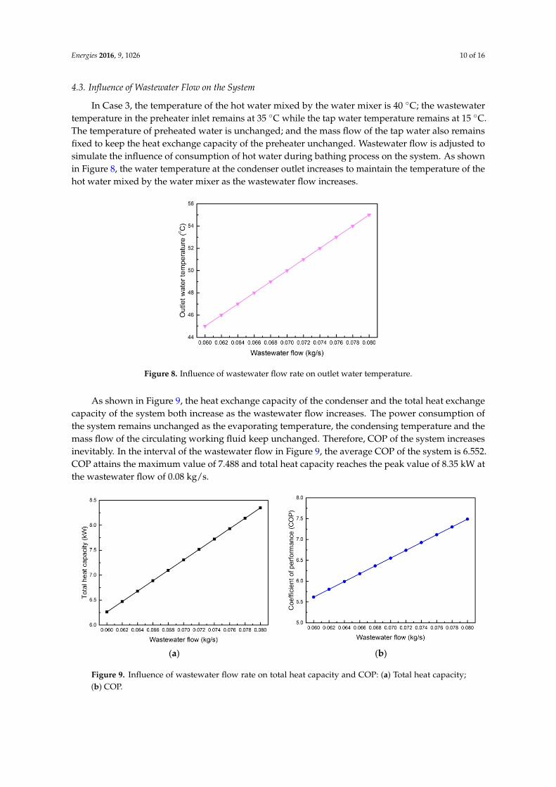
In Case 3, the temperature of the hot water mixed by the water mixer is 40 ◦C; the wastewatertemperature in the preheater inlet remains at 35 ◦C while the tap water temperature remains at 15 ◦C.The temperature of preheated water is unchanged; and the mass flow of the tap water also remainsfixed to keep the heat exchange capacity of the preheater unchanged. Wastewater flow is adjusted tosimulate the influence of consumption of hot water during bathing process on the system. As shownin Figure 8, the water temperature at the condenser outlet increases to maintain the temperature of thehot water mixed by the water mixer as the wastewater flow increases.
Energies 2016, 9, 1026 10 of 16
In Case 3, the temperature of the hot water mixed by the water mixer is 40 °C; the wastewater temperature in the preheater inlet remains at 35 °C while the tap water temperature remains at 15 °C. The temperature of preheated water is unchanged; and the mass flow of the tap water also remains fixed to keep the heat exchange capacity of the preheater unchanged. Wastewater flow is adjusted to simulate the influence of consumption of hot water during bathing process on the system. As shown in Figure 8, the water temperature at the condenser outlet increases to maintain the temperature of the hot water mixed by the water mixer as the wastewater flow increases.
Figure 8. Influence of wastewater flow rate on outlet water temperature.
As shown in Figure 9, the heat exchange capacity of the condenser and the total heat exchange capacity of the system both increase as the wastewater flow increases. The power consumption of the system remains unchanged as the evaporating temperature, the condensing temperature and the mass flow of the circulating working fluid keep unchanged. Therefore, COP of the system increases inevitably. In the interval of the wastewater flow in Figure 9, the average COP of the system is 6.552. COP attains the maximum value of 7.488 and total heat capacity reaches the peak value of 8.35 kW at the wastewater flow of 0.08 kg/s.
(a) (b)
Figure 9. Influence of wastewater flow rate on total heat capacity and COP: (a) Total heat capacity; (b) COP.
In Case 3, the heat exchange capacity of the air source evaporator and the power consumption of the system are constant. As shown in Figure 10, the heat exchange capacity of the wastewater source evaporator increases as the wastewater flow and the heat exchange capacity of the condenser increase. The wastewater temperature at the preheater inlet is 35 °C and the heat exchange capacity
Figure 8. Influence of wastewater flow rate on outlet water temperature.
As shown in Figure 9, the heat exchange capacity of the condenser and the total heat exchangecapacity of the system both increase as the wastewater flow increases. The power consumption ofthe system remains unchanged as the evaporating temperature, the condensing temperature and themass flow of the circulating working fluid keep unchanged. Therefore, COP of the system increasesinevitably. In the interval of the wastewater flow in Figure 9, the average COP of the system is 6.552.COP attains the maximum value of 7.488 and total heat capacity reaches the peak value of 8.35 kW atthe wastewater flow of 0.08 kg/s.
Energies 2016, 9, 1026 10 of 16
In Case 3, the temperature of the hot water mixed by the water mixer is 40 °C; the wastewater temperature in the preheater inlet remains at 35 °C while the tap water temperature remains at 15 °C. The temperature of preheated water is unchanged; and the mass flow of the tap water also remains fixed to keep the heat exchange capacity of the preheater unchanged. Wastewater flow is adjusted to simulate the influence of consumption of hot water during bathing process on the system. As shown in Figure 8, the water temperature at the condenser outlet increases to maintain the temperature of the hot water mixed by the water mixer as the wastewater flow increases.
Figure 8. Influence of wastewater flow rate on outlet water temperature.
As shown in Figure 9, the heat exchange capacity of the condenser and the total heat exchange capacity of the system both increase as the wastewater flow increases. The power consumption of the system remains unchanged as the evaporating temperature, the condensing temperature and the mass flow of the circulating working fluid keep unchanged. Therefore, COP of the system increases inevitably. In the interval of the wastewater flow in Figure 9, the average COP of the system is 6.552. COP attains the maximum value of 7.488 and total heat capacity reaches the peak value of 8.35 kW at the wastewater flow of 0.08 kg/s.
(a) (b)
Figure 9. Influence of wastewater flow rate on total heat capacity and COP: (a) Total heat capacity; (b) COP.
In Case 3, the heat exchange capacity of the air source evaporator and the power consumption of the system are constant. As shown in Figure 10, the heat exchange capacity of the wastewater source evaporator increases as the wastewater flow and the heat exchange capacity of the condenser increase. The wastewater temperature at the preheater inlet is 35 °C and the heat exchange capacity
Figure 9. Influence of wastewater flow rate on total heat capacity and COP: (a) Total heat capacity;(b) COP.
Energies 2016, 9, 1026 11 of 16
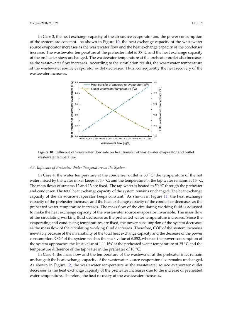
In Case 3, the heat exchange capacity of the air source evaporator and the power consumptionof the system are constant. As shown in Figure 10, the heat exchange capacity of the wastewatersource evaporator increases as the wastewater flow and the heat exchange capacity of the condenserincrease. The wastewater temperature at the preheater inlet is 35 ◦C and the heat exchange capacityof the preheater stays unchanged. The wastewater temperature at the preheater outlet also increasesas the wastewater flow increases. According to the simulation results, the wastewater temperatureat the wastewater source evaporator outlet decreases. Thus, consequently the heat recovery of thewastewater increases.
Energies 2016, 9, 1026 11 of 16
of the preheater stays unchanged. The wastewater temperature at the preheater outlet also increases as the wastewater flow increases. According to the simulation results, the wastewater temperature at the wastewater source evaporator outlet decreases. Thus, consequently the heat recovery of the wastewater increases.
Figure 10. Influence of wastewater flow rate on heat transfer of wastewater evaporator and outlet wastewater temperature.
4.4. Influence of Preheated Water Temperature on the System
In Case 4, the water temperature at the condenser outlet is 50 °C; the temperature of the hot water mixed by the water mixer keeps at 40 °C; and the temperature of the tap water remains at 15 °C. The mass flows of streams 12 and 13 are fixed. The tap water is heated to 50 °C through the preheater and condenser. The total heat exchange capacity of the system remains unchanged. The heat exchange capacity of the air source evaporator keeps constant. As shown in Figure 11, the heat exchange capacity of the preheater increases and the heat exchange capacity of the condenser decreases as the preheated water temperature increases. The mass flow of the circulating working fluid is adjusted to make the heat exchange capacity of the wastewater source evaporator invariable. The mass flow of the circulating working fluid decreases as the preheated water temperature increases. Since the evaporating and condensing temperatures are fixed, the power consumption of the system decreases as the mass flow of the circulating working fluid decreases. Therefore, COP of the system increases inevitably because of the invariability of the total heat exchange capacity and the decrease of the power consumption. COP of the system reaches the peak value of 6.552, whereas the power consumption of the system approaches the least value of 1.11 kW at the preheated water temperature of 25 °C and the temperature difference of the tap water in the preheater of 10 °C.
Figure 11. Influence of preheated water temperature on power consumption and COP.
Figure 10. Influence of wastewater flow rate on heat transfer of wastewater evaporator and outletwastewater temperature.
4.4. Influence of Preheated Water Temperature on the System
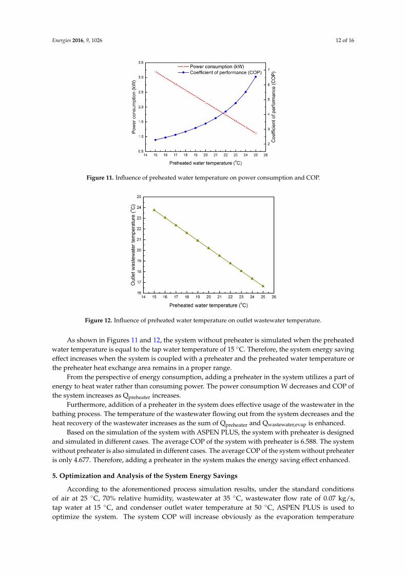
In Case 4, the water temperature at the condenser outlet is 50 ◦C; the temperature of the hotwater mixed by the water mixer keeps at 40 ◦C; and the temperature of the tap water remains at 15 ◦C.The mass flows of streams 12 and 13 are fixed. The tap water is heated to 50 ◦C through the preheaterand condenser. The total heat exchange capacity of the system remains unchanged. The heat exchangecapacity of the air source evaporator keeps constant. As shown in Figure 11, the heat exchangecapacity of the preheater increases and the heat exchange capacity of the condenser decreases as thepreheated water temperature increases. The mass flow of the circulating working fluid is adjustedto make the heat exchange capacity of the wastewater source evaporator invariable. The mass flowof the circulating working fluid decreases as the preheated water temperature increases. Since theevaporating and condensing temperatures are fixed, the power consumption of the system decreasesas the mass flow of the circulating working fluid decreases. Therefore, COP of the system increasesinevitably because of the invariability of the total heat exchange capacity and the decrease of the powerconsumption. COP of the system reaches the peak value of 6.552, whereas the power consumption ofthe system approaches the least value of 1.11 kW at the preheated water temperature of 25 ◦C and thetemperature difference of the tap water in the preheater of 10 ◦C.
In Case 4, the mass flow and the temperature of the wastewater at the preheater inlet remainunchanged; the heat exchange capacity of the wastewater source evaporator also remains unchanged.As shown in Figure 12, the wastewater temperature at the wastewater source evaporator outletdecreases as the heat exchange capacity of the preheater increases due to the increase of preheatedwater temperature. Therefore, the heat recovery of the wastewater increases.
Energies 2016, 9, 1026 12 of 16
Energies 2016, 9, 1026 11 of 16
of the preheater stays unchanged. The wastewater temperature at the preheater outlet also increases as the wastewater flow increases. According to the simulation results, the wastewater temperature at the wastewater source evaporator outlet decreases. Thus, consequently the heat recovery of the wastewater increases.
Figure 10. Influence of wastewater flow rate on heat transfer of wastewater evaporator and outlet wastewater temperature.
4.4. Influence of Preheated Water Temperature on the System
In Case 4, the water temperature at the condenser outlet is 50 °C; the temperature of the hot water mixed by the water mixer keeps at 40 °C; and the temperature of the tap water remains at 15 °C. The mass flows of streams 12 and 13 are fixed. The tap water is heated to 50 °C through the preheater and condenser. The total heat exchange capacity of the system remains unchanged. The heat exchange capacity of the air source evaporator keeps constant. As shown in Figure 11, the heat exchange capacity of the preheater increases and the heat exchange capacity of the condenser decreases as the preheated water temperature increases. The mass flow of the circulating working fluid is adjusted to make the heat exchange capacity of the wastewater source evaporator invariable. The mass flow of the circulating working fluid decreases as the preheated water temperature increases. Since the evaporating and condensing temperatures are fixed, the power consumption of the system decreases as the mass flow of the circulating working fluid decreases. Therefore, COP of the system increases inevitably because of the invariability of the total heat exchange capacity and the decrease of the power consumption. COP of the system reaches the peak value of 6.552, whereas the power consumption of the system approaches the least value of 1.11 kW at the preheated water temperature of 25 °C and the temperature difference of the tap water in the preheater of 10 °C.
Figure 11. Influence of preheated water temperature on power consumption and COP. Figure 11. Influence of preheated water temperature on power consumption and COP.
Energies 2016, 9, 1026 12 of 16
In Case 4, the mass flow and the temperature of the wastewater at the preheater inlet remain unchanged; the heat exchange capacity of the wastewater source evaporator also remains unchanged. As shown in Figure 12, the wastewater temperature at the wastewater source evaporator outlet decreases as the heat exchange capacity of the preheater increases due to the increase of preheated water temperature. Therefore, the heat recovery of the wastewater increases.
Figure 12. Influence of preheated water temperature on outlet wastewater temperature.
As shown in Figures 11 and 12, the system without preheater is simulated when the preheated water temperature is equal to the tap water temperature of 15 °C. Therefore, the system energy saving effect increases when the system is coupled with a preheater and the preheated water temperature or the preheater heat exchange area remains in a proper range.
From the perspective of energy consumption, adding a preheater in the system utilizes a part of energy to heat water rather than consuming power. The power consumption W decreases and COP of the system increases as Qpreheater increases.
Furthermore, addition of a preheater in the system does effective usage of the wastewater in the bathing process. The temperature of the wastewater flowing out from the system decreases and the heat recovery of the wastewater increases as the sum of Qpreheater and Qwastewater,evap is enhanced.
Based on the simulation of the system with ASPEN PLUS, the system with preheater is designed and simulated in different cases. The average COP of the system with preheater is 6.588. The system without preheater is also simulated in different cases. The average COP of the system without preheater is only 4.677. Therefore, adding a preheater in the system makes the energy saving effect enhanced.
5. Optimization and Analysis of the System Energy Savings
According to the aforementioned process simulation results, under the standard conditions of air at 25 °C, 70% relative humidity, wastewater at 35 °C, wastewater flow rate of 0.07 kg/s, tap water at 15 °C, and condenser outlet water temperature at 50 °C, ASPEN PLUS is used to optimize the system. The system COP will increase obviously as the evaporation temperature increases, the condensing temperature decreases, or the preheated water temperature increases, but the temperature cross of the evaporating temperature and the air temperature at the air source evaporator outlet or the wastewater temperature at the wastewater source evaporator outlet must be avoided while increasing the evaporating temperature. There is a limitation of the evaporating temperature. Similarly, the temperature cross of the condensing temperature and the water temperature at the condenser outlet must also be avoided when decreasing the condensing temperature. There is a limitation of the condensing temperature. When it comes to the preheater, there will be a temperature cross of the tap water and the wastewater if the preheated water temperature is increased with no limit. There is also a limitation of the preheated water temperature.
Figure 12. Influence of preheated water temperature on outlet wastewater temperature.
As shown in Figures 11 and 12, the system without preheater is simulated when the preheatedwater temperature is equal to the tap water temperature of 15 ◦C. Therefore, the system energy savingeffect increases when the system is coupled with a preheater and the preheated water temperature orthe preheater heat exchange area remains in a proper range.
From the perspective of energy consumption, adding a preheater in the system utilizes a part ofenergy to heat water rather than consuming power. The power consumption W decreases and COP ofthe system increases as Qpreheater increases.
Furthermore, addition of a preheater in the system does effective usage of the wastewater in thebathing process. The temperature of the wastewater flowing out from the system decreases and theheat recovery of the wastewater increases as the sum of Qpreheater and Qwastewater,evap is enhanced.
Based on the simulation of the system with ASPEN PLUS, the system with preheater is designedand simulated in different cases. The average COP of the system with preheater is 6.588. The systemwithout preheater is also simulated in different cases. The average COP of the system without preheateris only 4.677. Therefore, adding a preheater in the system makes the energy saving effect enhanced.
5. Optimization and Analysis of the System Energy Savings
According to the aforementioned process simulation results, under the standard conditionsof air at 25 ◦C, 70% relative humidity, wastewater at 35 ◦C, wastewater flow rate of 0.07 kg/s,tap water at 15 ◦C, and condenser outlet water temperature at 50 ◦C, ASPEN PLUS is used tooptimize the system. The system COP will increase obviously as the evaporation temperature
Energies 2016, 9, 1026 13 of 16
increases, the condensing temperature decreases, or the preheated water temperature increases, but thetemperature cross of the evaporating temperature and the air temperature at the air source evaporatoroutlet or the wastewater temperature at the wastewater source evaporator outlet must be avoidedwhile increasing the evaporating temperature. There is a limitation of the evaporating temperature.Similarly, the temperature cross of the condensing temperature and the water temperature at thecondenser outlet must also be avoided when decreasing the condensing temperature. There is alimitation of the condensing temperature. When it comes to the preheater, there will be a temperaturecross of the tap water and the wastewater if the preheated water temperature is increased with nolimit. There is also a limitation of the preheated water temperature.
Rising the preheated water temperature can reduce the mass flow of the system circulatingworking fluid effectively as the evaporating temperature increases and the condensing temperaturedecreases. The system COP increases and the power consumption of the system decreases whilekeeping the total heat exchange capacity of the system constant.
According to the analysis above, with the optimization of ASPEN PLUS, increasing theevaporating and preheated water temperatures or decreasing the condensing temperature and themass flow of the system circulating working fluid as much as possible will certainly increase theCOP of the system. The theoretical COP of the system reaches the highest value of 9.784 at theevaporating temperature of 14.96 ◦C, the condensing temperature of 48.74 ◦C, the preheated watertemperature of 27.19 ◦C. This peak COP is just a theoretical maximum and it may not be feasiblein practical applications. For example, while designing and manufacturing of the system too high,a preheated water temperature may rise the system COP effectively, but it will lead to problems suchas a heat exchange area that is too large and a heat exchanger without a compact structure becausethe water-water heat exchange of the preheater is single-phase heat exchange. Similarly, the increaseof the evaporating temperature, the decrease of the condensing temperature and the mass flow ofthe circulating working fluid will lead to a too large structure of heat exchanger. Thus it will goagainst miniaturizing the total structure even though the heat exchange of the air source evaporator,the wastewater source evaporator or the condenser is two-phase heat exchange. Therefore, whendesigning and manufacturing a practical system, more attention has to be paid to a compact, economicand efficient system, increasing COP of system and achieving high efficiency of energy utilization.
6. Conclusions
To ensure effective usage of heat of shower wastewater and humid air in the bathroom unit,this article proposes a dual heat source heat pump bathroom unit system feasible for family use.A preheater is added to it and the COP of the system is increased. Different system cases are simulatedwith the process simulation software ASPEN PLUS to get optimum operating parameters for differentcases. In addition, the energy saving effect of whether a preheater is installed in the system or not iscompared and analyzed. The conclusions of this article can be summarized as below:
(1) Different cases of the system are simulated. The energy saving effect and the heat recovery of thewastewater increase as inlet wastewater temperature increases, tap water temperature decreases,or wastewater flow increases;
(2) The system with or without preheater is simulated. The system energy saving effect increaseswhen the system is coupled with preheater and the preheated water temperature or the preheaterheat exchange area are kept in a proper range;
(3) Based on the optimization and analysis, under the standard conditions of air at 25 ◦C, relativehumidity of 70%, wastewater at 35 ◦C, wastewater flow rate of 0.07 kg/s, tap water at 15 ◦C,and condenser outlet water temperature at 50 ◦C, the theoretical COP of the system can reach9.784 at the evaporating temperature of 14.96 ◦C, the condensing temperature of 48.74 ◦C, and thepreheated water temperature of 27.19 ◦C.
Energies 2016, 9, 1026 14 of 16
(4) The COPs of the system of a household dual heat source heat pump water heater with andwithout preheater are 6.588 and 4.677, respectively. The energy saving effect of the system ofhousehold dual heat source heat pump water heater with preheater is better than that withouta preheater.
Acknowledgments: This work was financially supported by the National Natural Science Foundation of China(Grant No. 51276055) and the Hebei Applied Basic Research Program of China (Grant No. 13964503D).
Author Contributions: Xiang Gou conceived the research. Yang Fu and Xiang Gou carried out the simulation.Xiang Gou, Yang Fu, Imran Ali Shah, Yamei Li, Guoyou Xu and Yue Yang participated in the analysis of the dataand writing the initial manuscript. Xiang Gou, Imran Ali Shah, Enyu Wang, Liansheng Liu and Jinxiang Wurevised the manuscript and adjusted the data presentation. All authors have read and approved the manuscript.
Conflicts of Interest: The authors declare no conflict of interest.
Abbreviations
The following abbreviations are used in this manuscript:
A heat exchange area of heat exchanger, (m2)c specific heat, J/(kg·K)COP coefficient of the system performanceDuty duty, (W)F correction factor of Log mean temperature difference (LMTD)h enthalpy, (J/kg)HeatFlow heat flow, (W)M mass flow, (kg/s)p pressure, (Pa)Q heat exchange capacity, (W)Qtotal total heat exchange capacity of system, (W)Qloss, Qleak heat loss of heat exchanger, (W)R gas constant, (J/(mol·K))S velocity, (m/s)T temperature, (K)4TLM LMTD of heat exchanger, (K)U heat exchange coefficient of heat exchanger, (W/(m2·K))Vm ideal gas molar volume, (m3/mol)v specific volume, (m3/mol)W power consumption, (W)Z compressibility factorω acentric factorSubscriptsc criticalre reducedprev previous modulenext next moduleout outletin inlethot hot fluidcold cold fluidr circulating working fluidcooler coolerheatx heat exchangerdis compressor outletsuc compressor inletv valveair,evap air source evaporatorwastewater,evap wastewater source evaporatorcond condenserpreheater preheater
Energies 2016, 9, 1026 15 of 16
References
1. Zhang, D.L.; Huang, G.Q.; Xu, Y.M.; Gong, Q.H. Waste-to-Energy in China: Key Challenges andOpportunities. Energies 2015, 8, 14182–14196. [CrossRef]
2. Qu, J.S.; Maraseni, T.; Liu, L.N.; Zhang, Z.Q.; Yusaf, T. A Comparison of Household Carbon EmissionPatterns of Urban and Rural China over the 17 Year Period (1995–2011). Energies 2015, 8, 10537–10557.[CrossRef]
3. Nam, Y.J.; Gao, X.Y.; Yoon, S.H.; Lee, K.H. Study on the Performance of a Ground Source Heat Pump SystemAssisted by Solar Thermal Storage. Energies 2015, 8, 13378–13394. [CrossRef]
4. Kim, J.S.; Nam, Y.J. A Numerical Study on System Performance of Groundwater Heat Pumps. Energies 2016,9, 4. [CrossRef]
5. Hepbasli, A.; Kalinci, Y. A review of heat pump water heating systems. Renew. Sustain. Energy Rev. 2009, 13,1211–1229. [CrossRef]
6. Ni, L.; Dong, J.K.; Yao, S.; Shen, C.; Qv, D.H.; Zhang, X.D. A review of heat pump systems for heating andcooling of buildings in China in the last decade. Renew. Energy 2016, 84, 30–45. [CrossRef]
7. Touchie, M.F.; Pressnail, K.D. Testing and simulation of a low-temperature air-source heat pump operatingin a thermal buffer zone. Energy Build. 2014, 75, 149–159. [CrossRef]
8. Ma, G.Y.; Zhao, H.X. Experimental study of a heat pump system with flash-tank coupled with scrollcompressor. Energy Build. 2008, 40, 697–701. [CrossRef]
9. Xu, S.X.; Ma, G.Y. Research on air-source heat pump coupled with economized vapor injection scrollcompressor and ejector. Int. J. Refrig. 2011, 34, 1587–1595. [CrossRef]
10. Safa, A.A.; Fung, A.S.; Kumar, R. Performance of two-stage variable capacity air source heat pump: Fieldperformance results and TRNSYS simulation. Energy Build. 2015, 94, 80–90. [CrossRef]
11. Wu, J.H.; Lin, J. Thermodynamic analysis of a novel heat pump water heater with two-stage heating for agreat rise of water temperature. Energy Build. 2015, 91, 97–104. [CrossRef]
12. Bhattacharyya, S.; Garai, A.; Sarkar, J. Thermodynamic analysis and optimization of a novel N2O–CO2
cascade system for refrigeration and heating. Int. J. Refrig. 2009, 32, 1077–1084. [CrossRef]13. Getu, H.M.; Bansal, P.K. Thermodynamic analysis of an R744–R717 cascade refrigeration system. Int. J. Refrig.
2008, 31, 45–54. [CrossRef]14. Fernandez, N.; Hwang, Y.; Radermacher, R. Comparison of CO2 heat pump water heater performance with
baseline cycle and two high COP cycles. Int. J. Refrig. 2010, 33, 635–644. [CrossRef]15. Zhang, J.F.; Qin, Y.; Wang, C.C. Review on CO2 heat pump water heater for residential use in Japan.
Renew. Sustain. Energy Rev. 2015, 50, 1383–1391. [CrossRef]16. Wu, H.G.; Shu, P.G.; Xing, Z.W. Experimental study on performance of air source heat pumps with alternative
refrigerants. Heat. Vent. Air Cond. 2006, 36, 61–62.17. Dong, J.K.; Li, S.; Yao, Y.; Jiang, Y.Q.; Tian, Y.; Tian, H. Defrosting performances of a multi-split air source
heat pump with phase change thermal storage. Int. J. Refrig. 2015, 55, 49–59. [CrossRef]18. Hu, W.J.; Jiang, Y.Q.; Qv, M.L.; Ni, L.; Yao, Y.; Deng, S.M. An experimental study on the operating performance
of a novel reverse-cycle hot gas defrosting method for air source heat pumps. Appl. Therm. Eng. 2011, 31,363–369.
19. Seong, Y.B.; Lim, J.H. Energy saving potentials of phase change materials applied to lightweight buildingenvelopes. Energies 2013, 6, 5219–5230. [CrossRef]
20. Lazzarin, R.M. Dual source heat pump systems: Operation and performance. Energy Build. 2012, 52, 77–85.[CrossRef]
21. Liu, Y.; Ma, J.; Zhou, G.H.; Zhang, C.; Wan, W.L. Performance of a solar air composite heat source heat pumpsystem. Renew. Energy 2016, 87, 1053–1058. [CrossRef]
22. Tian, Y.; Shi, W.X.; Wang, B.L. A new ground-coupled heat pump system integrated with a multi-modeair-source heat compensator to eliminate thermal imbalance in cold regions. Energy Build. 2015, 107, 103–112.
23. Congedo, P.M.; Lorusso, C.; Giorgi, M.G.D.; Laforgia, D. Computational fluid dynamic modeling ofhorizontal air-ground heat exchangers (HAGHE) for HVAC systems. Energies 2014, 7, 8465–8482. [CrossRef]
24. Hepbasli, A.; Biyik, E.; Ekren, O.; Gunerhan, H.; Araz, M. A key review of wastewater source heat pump(WWSHP) systems. Energy Convers. Manag. 2014, 88, 700–722. [CrossRef]
Energies 2016, 9, 1026 16 of 16
25. Tanha, K.; Fung, A.S.; Kuma, R. Performance of two domestic solar water heaters with drain water heatrecovery units: Simulation and experimental investigation. Appl. Therm. Eng. 2015, 90, 444–459. [CrossRef]
26. Liu, L.B.; Fu, L.; Jiang, Y. Application of an exhaust heat recovery system for domestic hot water. Energy2010, 35, 1476–1481. [CrossRef]
27. Kahraman, A.; Çelebi, A. Investigation of the Performance of a Heat Pump Using Waste Water as a HeatSource. Energies 2009, 2, 697–713. [CrossRef]
28. Wong, L.T.; Mui, K.W.; Guan, Y. Shower water heat recovery in high-rise residential buildings of Hong Kong.Appl. Energy 2010, 87, 703–709. [CrossRef]
29. Liu, L.B.; Fu, L.; Zhang, S.G. The design and analysis of two exhaust heat recovery systems for public showerfacilities. Appl. Energy 2014, 132, 267–275. [CrossRef]
30. Chen, W.; Liang, S.Q.; Guo, Y.X.; Cheng, K.Y.; Gui, X.H.; Tang, D.W. Investigation on the thermal performanceand optimization of a heat pump water heater assisted wish shower waste water. Energy Build. 2013, 64,172–181. [CrossRef]
31. Dong, J.K.; Zhang, Z.; Yao, Y.; Jiang, Y.Q.; Lei, B. Experimental performance evaluation of a novel heat pumpwater heater assisted with shower drain water. Appl. Energy 2015, 154, 842–850. [CrossRef]
32. Chen, Z.S.; Tao, W.Q.; Zhu, Y.W.; Hu, P. Performance analysis of air-water dual source heat pump waterheater with heat recovery. Sci. China Technol. Sci. 2012, 55, 2148–2156. [CrossRef]
33. Zhang, C.; Dong, J.Y.; Zhao, X.D.; Zhou, G.H. The influence factors of the compound heat-exchangingtemperature difference of dual-source compound heat-exchanger. Cryog. Supercond. 2012, 40, 68–72.
34. Zhang, C.; Dong, J.Y.; Zhao, X.D.; Zhou, G.H. Structure parameter optimization of air-water dual-sourcecompound heat-exchanger. Fluid Mach. 2012, 40, 61–64.
35. Mansouri, R.; Boukholda, I.; Bourouis, M.; Bellagi, A. Modelling and testing the performance of a commercialammonia/water absorption chiller using Aspen-Plus platform. Energy 2015, 93, 2374–2383. [CrossRef]
36. De Guido, G.; Langè, S.; Pellegrini, L.A. Refrigeration cycles in low-temperature distillation processes for thepurification of natural gas. J. Nat. Gas Sci. Eng. 2015, 27, 887–900. [CrossRef]
37. Somers, C.; Mortazavi, A.; Hwang, Y.; Radermacher, R.; Rodgers, P.; Al-Hashimi, S. Modeling water/lithiumbromide absorption chillers in ASPEN Plus. Appl. Energy 2011, 88, 4197–4205. [CrossRef]
38. Peng, D.Y.; Robinson, D.B. A New Two-Constant Equation of State. Ind. Eng. Chem. Fundam. 1976, 15, 59–64.[CrossRef]
39. Soave, G. Equilibrium constants from a modified Redlich-Kwong equation of state. Chem. Eng. Sci. 1972, 27,1197–1203. [CrossRef]
40. Spencer, R.C.; Meyer, C.A. The 1967 ASME Steam tables. Nav. Eng. J. 1968, 80, 751–758.
© 2016 by the authors; licensee MDPI, Basel, Switzerland. This article is an open accessarticle distributed under the terms and conditions of the Creative Commons Attribution(CC-BY) license (http://creativecommons.org/licenses/by/4.0/).


![Utpl Ingenieria Quimica 2008 Aspen Plus[1]](https://img.pdfslide.tips/doc/110x75/55cf9695550346d0338c796e/utpl-ingenieria-quimica-2008-aspen-plus1.jpg)