Embed Size (px)
Citation preview
Raspberry Pi projects • Make a switch • Control volume • Measuring temperature • Measuring light • Output PWM • Blink LEDs • Remote-‐control car • Installing VNC
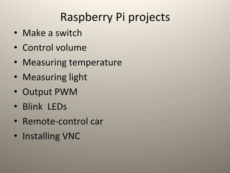
• Raspberry Pi的GPIO只能接收及送出數位的訊號, 類比訊號就要 做轉換成數位訊號才能輸入。 • 其中一個選擇是Arduino ,這是一個應用很廣的數位板(大致 能做的事如下表所示),有很多的使用者。 • 類似的還有Gertboard及piface , 而這兩個都是為Raspberry Pi 設計的產品。
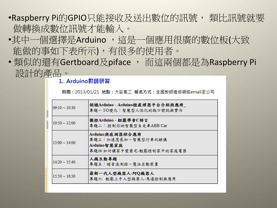
TesLng gpio pins: $gpio mode 0 out $gpio write 0 1
More usages of Raspberry Pi
• Adopted from “Using adafruit MCP+Gpio to control volume”
hSp://www.adafruit.com/
• hSps://projects.drogon.net/raspberry-‐pi/ • www.raspberrypi.org
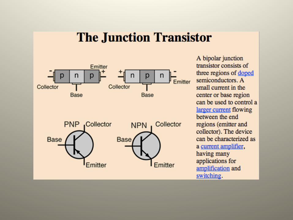
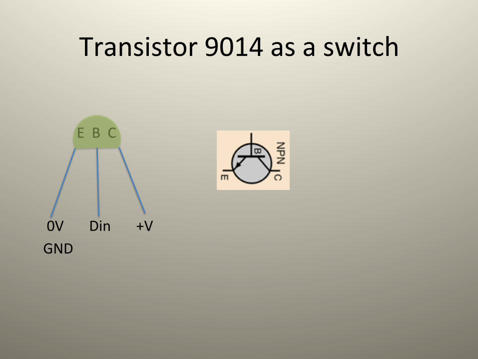
Transistor 9014 as a switch
E B C 0V Din +V GND
Using MCP3008 to control volume
• Parts: tripotenLal meter , mcp3008, speaker
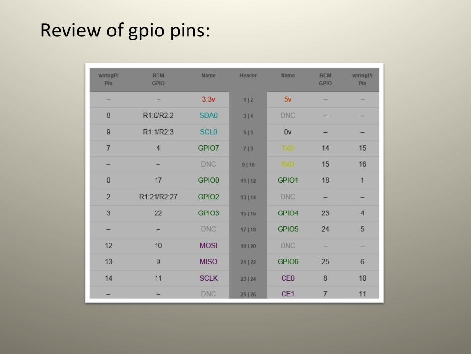
Review of gpio pins:

MCP3008 : analog to digital converter
MCP3008 pins 9~16 are :
1
2
3
4
5
6
7
8
9
10
11
12
13
14
15
16
A D
VDD VREF AGND CLK DOUT DIN CS/SHDN DGND
GPIO pins 3.3V 3.3V GND #18 #23 #24 #25 GND
Analog input
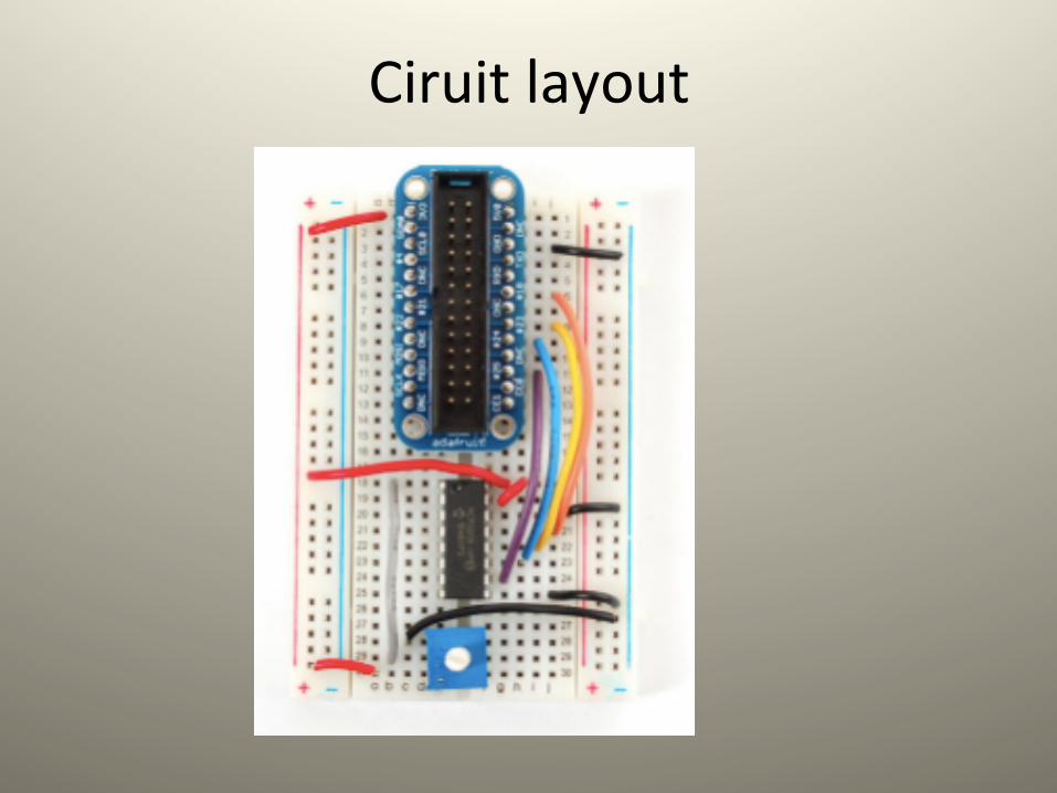
Ciruit layout
Python script for the volume control
• The script is fairly simple. Half of the code (the readadc funcLon) is a funcLon that will 'talk' to the MCP3008 chip using four digital pins to 'bit bang' the SPI interface (this is because not all Raspberry Pi's have the hardware SPI funcLon)
• The MCP3008 is a 10-‐bit ADC. That means it will read a value from 0 to 1023 (2^^10 = 1024 values) where 0 is the same and 'ground' and '1023' is the same as '3.3 volts'. We don't convert the number to voltage although its easy to do that by mulLplying the number by (3.3 / 1023).
• We check to see if the pot was turned more than 5 counts -‐ this keeps us from being too 'jiSery' and resehng the volume too oien. The raw analog count number is then converted into a volume percentage of 0%-‐100%. When the trimpot is turned up or down it will print the volume level to STDOUT and adjust the audio level of the playing file by telling the mixer to adjust the volume.
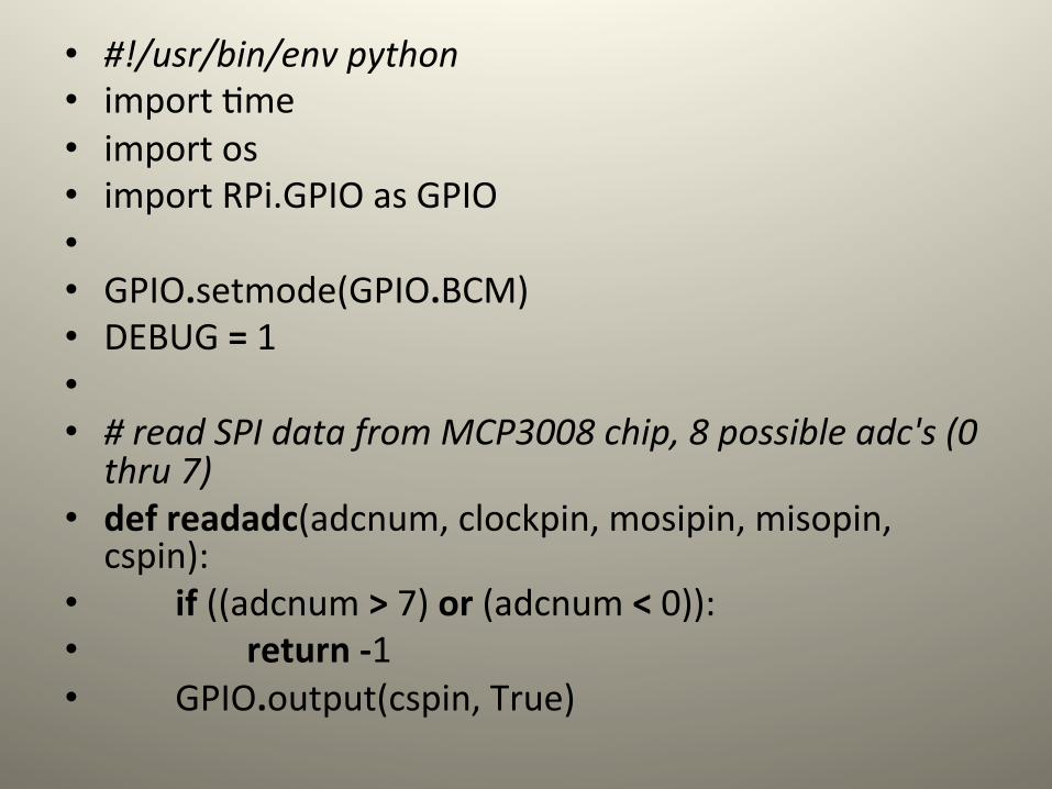
• #!/usr/bin/env python • import Lme • import os • import RPi.GPIO as GPIO • • GPIO.setmode(GPIO.BCM) • DEBUG = 1 • • # read SPI data from MCP3008 chip, 8 possible adc's (0 thru 7)
• def readadc(adcnum, clockpin, mosipin, misopin, cspin):
• if ((adcnum > 7) or (adcnum < 0)): • return -‐1 • GPIO.output(cspin, True)
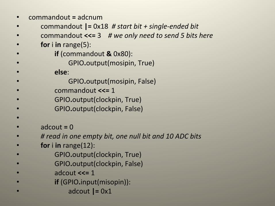
• commandout = adcnum • commandout |= 0x18 # start bit + single-‐ended bit • commandout <<= 3 # we only need to send 5 bits here • for i in range(5): • if (commandout & 0x80): • GPIO.output(mosipin, True) • else: • GPIO.output(mosipin, False) • commandout <<= 1 • GPIO.output(clockpin, True) • GPIO.output(clockpin, False) • • adcout = 0 • # read in one empty bit, one null bit and 10 ADC bits • for i in range(12): • GPIO.output(clockpin, True) • GPIO.output(clockpin, False) • adcout <<= 1 • if (GPIO.input(misopin)): • adcout |= 0x1
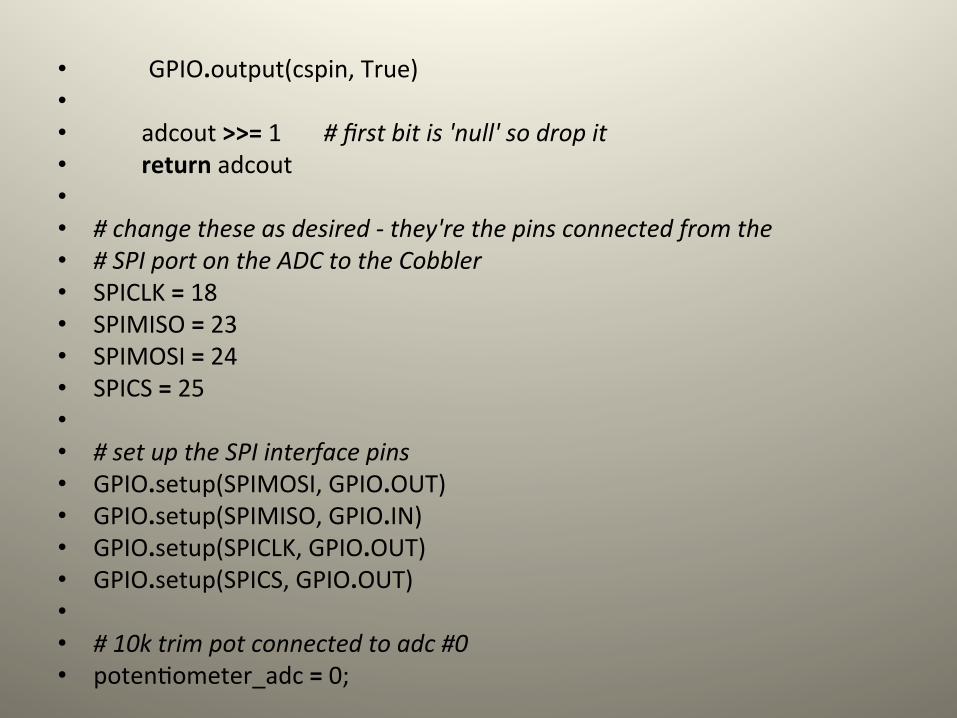
• GPIO.output(cspin, True) • • adcout >>= 1 # first bit is 'null' so drop it • return adcout • • # change these as desired -‐ they're the pins connected from the • # SPI port on the ADC to the Cobbler • SPICLK = 18 • SPIMISO = 23 • SPIMOSI = 24 • SPICS = 25 • • # set up the SPI interface pins • GPIO.setup(SPIMOSI, GPIO.OUT) • GPIO.setup(SPIMISO, GPIO.IN) • GPIO.setup(SPICLK, GPIO.OUT) • GPIO.setup(SPICS, GPIO.OUT) • • # 10k trim pot connected to adc #0 • potenLometer_adc = 0;
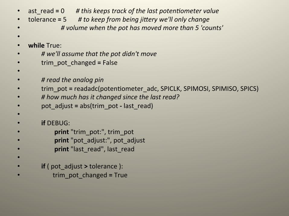
• ast_read = 0 # this keeps track of the last potenOometer value • tolerance = 5 # to keep from being jiQery we'll only change • # volume when the pot has moved more than 5 'counts' • • while True: • # we'll assume that the pot didn't move • trim_pot_changed = False • • # read the analog pin • trim_pot = readadc(potenLometer_adc, SPICLK, SPIMOSI, SPIMISO, SPICS) • # how much has it changed since the last read? • pot_adjust = abs(trim_pot -‐ last_read) • • if DEBUG: • print "trim_pot:", trim_pot • print "pot_adjust:", pot_adjust • print "last_read", last_read • • if ( pot_adjust > tolerance ): • trim_pot_changed = True
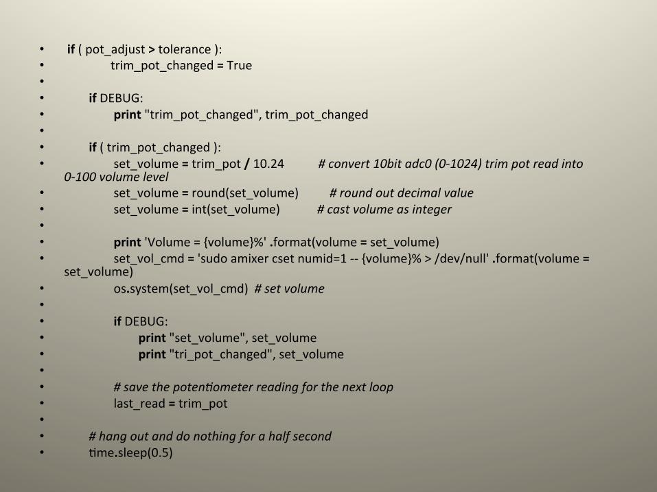
• if ( pot_adjust > tolerance ): • trim_pot_changed = True • • if DEBUG: • print "trim_pot_changed", trim_pot_changed • • if ( trim_pot_changed ): • set_volume = trim_pot / 10.24 # convert 10bit adc0 (0-‐1024) trim pot read into
0-‐100 volume level • set_volume = round(set_volume) # round out decimal value • set_volume = int(set_volume) # cast volume as integer • • print 'Volume = {volume}%' .format(volume = set_volume) • set_vol_cmd = 'sudo amixer cset numid=1 -‐-‐ {volume}% > /dev/null' .format(volume =
set_volume) • os.system(set_vol_cmd) # set volume • • if DEBUG: • print "set_volume", set_volume • print "tri_pot_changed", set_volume • • # save the potenOometer reading for the next loop • last_read = trim_pot • • # hang out and do nothing for a half second • Lme.sleep(0.5)
Analogue Sensors On The Raspberry Pi Using An MCP3008
• Parts: Raspberry Pi MCP3008 8 channel ADC Light dependent resistor (LDR) TMP36 temperature sensor 10 Kohm resistor
source from: hSp://www.raspberrypi-‐spy.co.uk/2013/10/analogue-‐sensors-‐on-‐the-‐raspberry-‐pi-‐using-‐an-‐mcp3008/
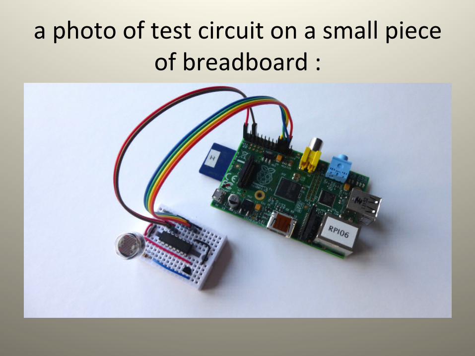
a photo of test circuit on a small piece of breadboard :
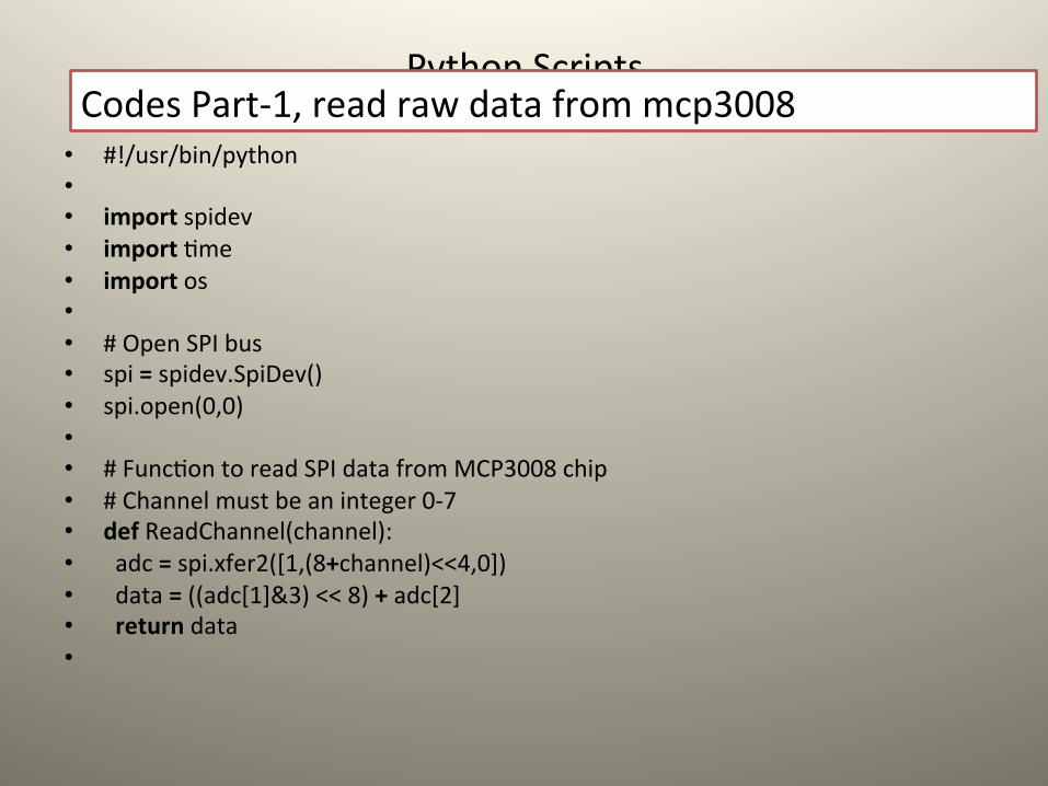
Python Scripts
• #!/usr/bin/python • • import spidev • import Lme • import os • • # Open SPI bus • spi = spidev.SpiDev() • spi.open(0,0) • • # FuncLon to read SPI data from MCP3008 chip • # Channel must be an integer 0-‐7 • def ReadChannel(channel): • adc = spi.xfer2([1,(8+channel)<<4,0]) • data = ((adc[1]&3) << 8) + adc[2] • return data •
Codes Part-‐1, read raw data from mcp3008
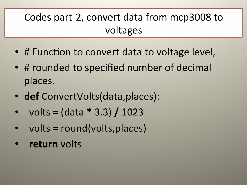
• # FuncLon to convert data to voltage level, • # rounded to specified number of decimal places.
• def ConvertVolts(data,places): • volts = (data * 3.3) / 1023 • volts = round(volts,places) • return volts
Codes part-‐2, convert data from mcp3008 to voltages
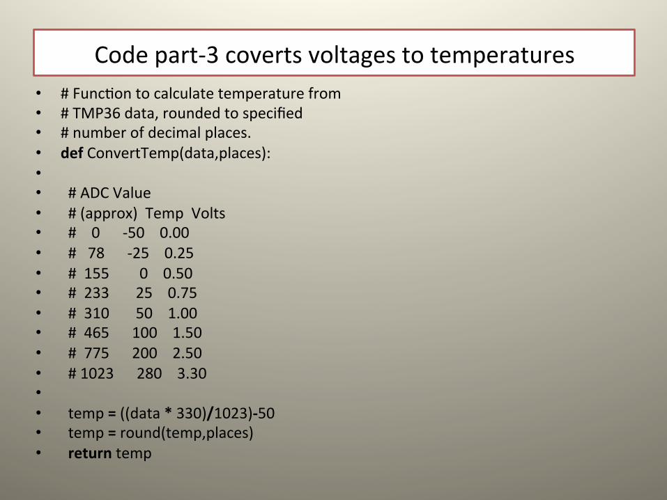
Code part-‐3 coverts voltages to temperatures • # FuncLon to calculate temperature from • # TMP36 data, rounded to specified • # number of decimal places. • def ConvertTemp(data,places): • • # ADC Value • # (approx) Temp Volts • # 0 -‐50 0.00 • # 78 -‐25 0.25 • # 155 0 0.50 • # 233 25 0.75 • # 310 50 1.00 • # 465 100 1.50 • # 775 200 2.50 • # 1023 280 3.30 • • temp = ((data * 330)/1023)-‐50 • temp = round(temp,places) • return temp
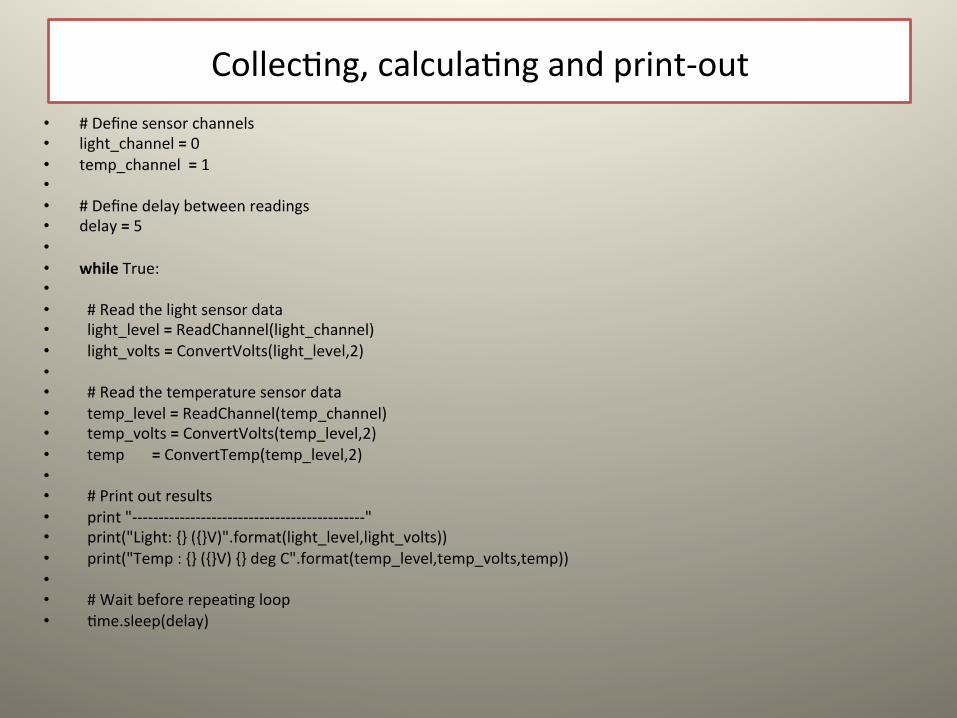
CollecLng, calculaLng and print-‐out • # Define sensor channels • light_channel = 0 • temp_channel = 1 • • # Define delay between readings • delay = 5 • • while True: • • # Read the light sensor data • light_level = ReadChannel(light_channel) • light_volts = ConvertVolts(light_level,2) • • # Read the temperature sensor data • temp_level = ReadChannel(temp_channel) • temp_volts = ConvertVolts(temp_level,2) • temp = ConvertTemp(temp_level,2) • • # Print out results • print "-‐-‐-‐-‐-‐-‐-‐-‐-‐-‐-‐-‐-‐-‐-‐-‐-‐-‐-‐-‐-‐-‐-‐-‐-‐-‐-‐-‐-‐-‐-‐-‐-‐-‐-‐-‐-‐-‐-‐-‐-‐-‐-‐-‐" • print("Light: {} ({}V)".format(light_level,light_volts)) • print("Temp : {} ({}V) {} deg C".format(temp_level,temp_volts,temp)) • • # Wait before repeaLng loop • Lme.sleep(delay)
Using PWM in RPi.GPIO
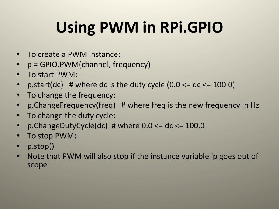
• To create a PWM instance: • p = GPIO.PWM(channel, frequency) • To start PWM: • p.start(dc) # where dc is the duty cycle (0.0 <= dc <= 100.0) • To change the frequency: • p.ChangeFrequency(freq) # where freq is the new frequency in Hz • To change the duty cycle: • p.ChangeDutyCycle(dc) # where 0.0 <= dc <= 100.0 • To stop PWM: • p.stop() • Note that PWM will also stop if the instance variable 'p goes out of
scope
An example to blink an LED once every two seconds
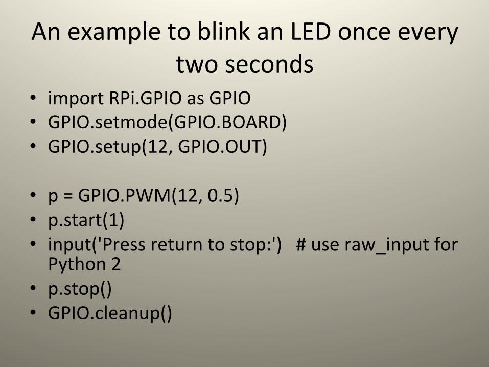
• import RPi.GPIO as GPIO • GPIO.setmode(GPIO.BOARD) • GPIO.setup(12, GPIO.OUT)
• p = GPIO.PWM(12, 0.5) • p.start(1) • input('Press return to stop:') # use raw_input for Python 2
• p.stop() • GPIO.cleanup()
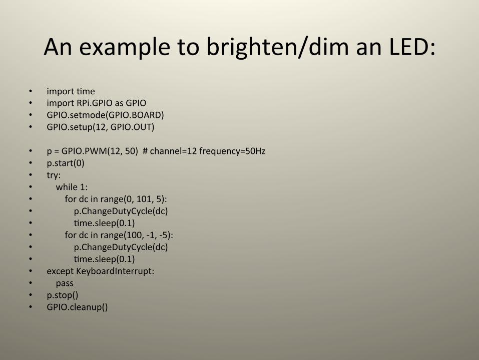
An example to brighten/dim an LED: • import Lme • import RPi.GPIO as GPIO • GPIO.setmode(GPIO.BOARD) • GPIO.setup(12, GPIO.OUT)
• p = GPIO.PWM(12, 50) # channel=12 frequency=50Hz • p.start(0) • try: • while 1: • for dc in range(0, 101, 5): • p.ChangeDutyCycle(dc) • Lme.sleep(0.1) • for dc in range(100, -‐1, -‐5): • p.ChangeDutyCycle(dc) • Lme.sleep(0.1) • except KeyboardInterrupt: • pass • p.stop() • GPIO.cleanup()
Remote-‐control car
• Parts: 2 server motor, Raspberry pi with Adafruit assembled cobbler breakout and cables, baSery for motors,
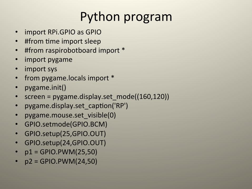
Python program • import RPi.GPIO as GPIO • #from Lme import sleep • #from raspirobotboard import * • import pygame • import sys • from pygame.locals import * • pygame.init() • screen = pygame.display.set_mode((160,120)) • pygame.display.set_capLon('RP') • pygame.mouse.set_visible(0) • GPIO.setmode(GPIO.BCM) • GPIO.setup(25,GPIO.OUT) • GPIO.setup(24,GPIO.OUT) • p1 = GPIO.PWM(25,50) • p2 = GPIO.PWM(24,50)
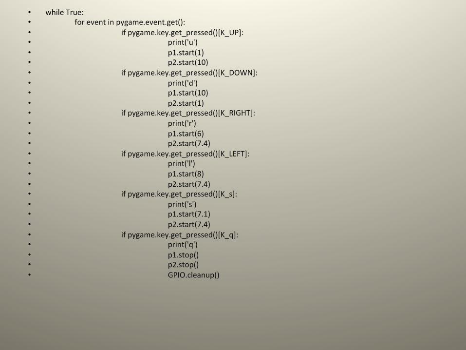
• while True: • for event in pygame.event.get(): • if pygame.key.get_pressed()[K_UP]: • print('u') • p1.start(1) • p2.start(10) • if pygame.key.get_pressed()[K_DOWN]: • print('d') • p1.start(10) • p2.start(1) • if pygame.key.get_pressed()[K_RIGHT]: • print('r') • p1.start(6) • p2.start(7.4) • if pygame.key.get_pressed()[K_LEFT]: • print('l') • p1.start(8) • p2.start(7.4) • if pygame.key.get_pressed()[K_s]: • print('s') • p1.start(7.1) • p2.start(7.4) • if pygame.key.get_pressed()[K_q]: • print('q') • p1.stop() • p2.stop() • GPIO.cleanup()
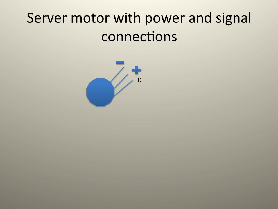
Server motor with power and signal connecLons
D
Installing VNC on raspberry pi
• hSp://learn.adafruit.com/adafruit-‐raspberry-‐pi-‐lesson-‐7-‐remote-‐control-‐with-‐vnc/installing-‐vnc


![電機資訊工程概論 1011107 [相容模式] · 語音訊號 處理 三上 三下 四上 四下 碩上 碩下 數位影像 處理 隨機訊號與 統計訊號處 理概論 數位影像](https://img.pdfslide.tips/doc/110x75/5e1885ac9cdf851a9653a9e5/eeece-1011107-c-eeee-ec-.jpg)