Embed Size (px)
Citation preview
RHB-200Keypad Connecting Hub
TUNCD
MUTE
MP3
OFF
AV
V
V
RKP-200Learning Keypad
2 RKP-200/RHB-200
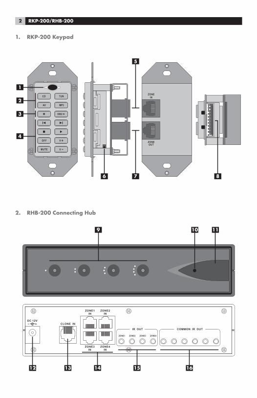
1. RKP-200 Keypad
2. RHB-200 Connecting Hub
TUNCD
MUTE
MP3
OFF
AV
V
V ZONEOUT
ZONEIN
�
�
�
�
�
� ��
DC 12VCLONE IN
ZONE1IN
ZONE3IN
ZONE4IN
ZONE2IN
IR OUT
ZONE3 ZONE4ZONE1
COMMON IR OUT
ZONE2
� ����
����������
3
LIGHT
LIGHT
DC 12VCLONE IN
ZONE1IN
ZONE3IN
ZONE4IN
ZONE2IN
IR OUT
ZONE3 ZONE4ZONE1
COMMON IR OUT
ZONE2
TUNCD
MUTE
MP3
OFF
AV
V
VZONEOUT
ZONEIN
TUNCD
MUTE
MP3
OFF
AV
V
VZONEOUT
ZONEIN
TUNCD
MUTE
MP3
OFF
AV
V
V ZONEOUT
ZONEIN
TUNCD
MUTE
MP3
OFF
AV
V
V ZONEOUT
ZONEIN
TUNCD
MUTE
MP3
OFF
AV
V
VZONEOUT
ZONEIN TUNCD
MUTE
MP3
OFF
AV
V
V ZONEOUT
ZONEIN
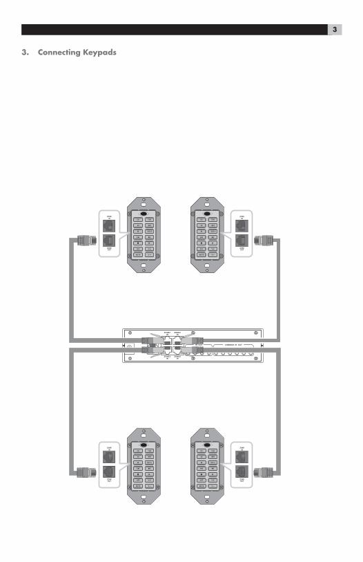
3. Connecting Keypads
4 RKP-200/RHB-200
1 2 3
4 5 6
7 8 9
+10 0 X
C M
S R
ENT
FRQ DIRECT MENUGUIDE
TUNE PRESET
FM MONO BAND
CTR
SUB SUR
SEARCH- SEARCH+
OSD
ON OFF
SMT MUTE
CH VOL
POWER
SMARTMEM
AUD CD TUN TAPE EXT
V1 V2 V3 V4 V5
DEVICE / INPUT
RR-1060
DC 12VCLONE IN
ZONE1IN
ZONE3IN
ZONE4IN
ZONE2IN
IR OUT
ZONE3 ZONE4ZONE1
COMMON IR OUT
ZONE2
���
���
��
����������������������������������
�����������
����������������������������������������
����������������������������
������� ���
������ ���
������� ������� ����������������
���������
���������
�������� ���
���������
��������������������������
���
������ ������
���
������
�
�������
������������
����� ����
����� ����
���������
�
��������������������������������������������������
��������������������������
����� �����
�
�
�
�
������
�������
��������� �
������������� ����������������
�
������� �������
������ �������������
�������������
��
���������������
���
�����
���� ����������������������������������������
����������������������
������������
�������������
����������������������������������������������������������������������������������������������������������������������������������������������������������������������������������������������������������������������������������������������������������������������������������
�����������������������������������������������������������������������������������
�������������������������������������������������������������������������������������������������������������������������������������
���������������������������������������������������������������������
�������������������������������������������������������������������������
����������������������������������������������������������������������
������������������������������������������������������������������
�������������������
����������������
���������������������
���������������
��������������������
��������������������
����������
�����������
�����������
�������
���� ����� ����
�����
���������� �����
�����
���������
���� ���������������
������������������
����� ����������������� �������
������ �������������� ����
������ � �
����� � ��
���������������������������������
������� �������� ��������������
�������������������
�������������
��������������
������
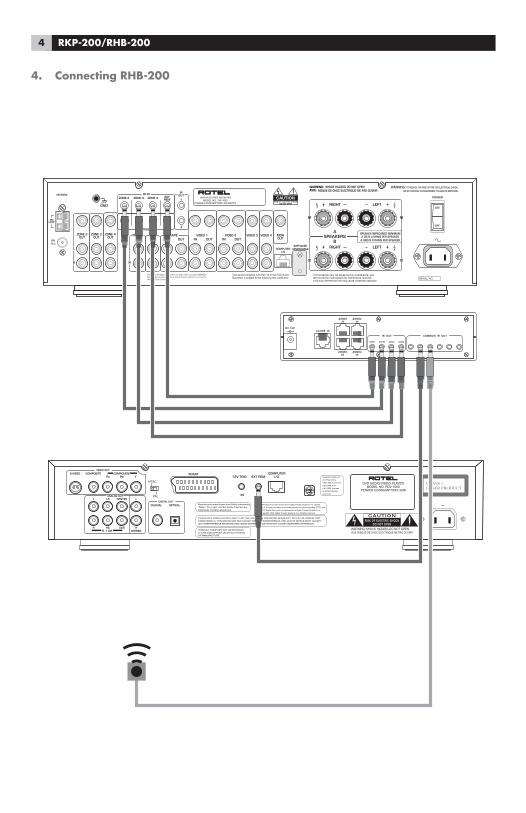
4. Connecting RHB-200
5
DC 12VCLONE IN
ZONE1IN
ZONE3IN
ZONE4IN
ZONE2IN
IR OUT
ZONE3 ZONE4ZONE1
COMMON IR OUT
ZONE2
TUNCD
MUTE
MP3
OFF
AV
V
VZONEOUT
ZONEIN
TUNCD
MUTE
MP3
OFF
AV
V
VZONEOUT
ZONEIN
TUNCD
MUTE
MP3
OFF
AV
V
V ZONEOUT
ZONEIN
TUNCD
MUTE
MP3
OFF
AV
V
V ZONEOUT
ZONEIN
TUNCD
MUTE
MP3
OFF
AV
V
VZONEOUT
ZONEIN TUNCD
MUTE
MP3
OFF
AV
V
V ZONEOUT
ZONEIN
TUNCD
MUTE
MP3
OFF
AV
V
V ZONEOUT
ZONEIN
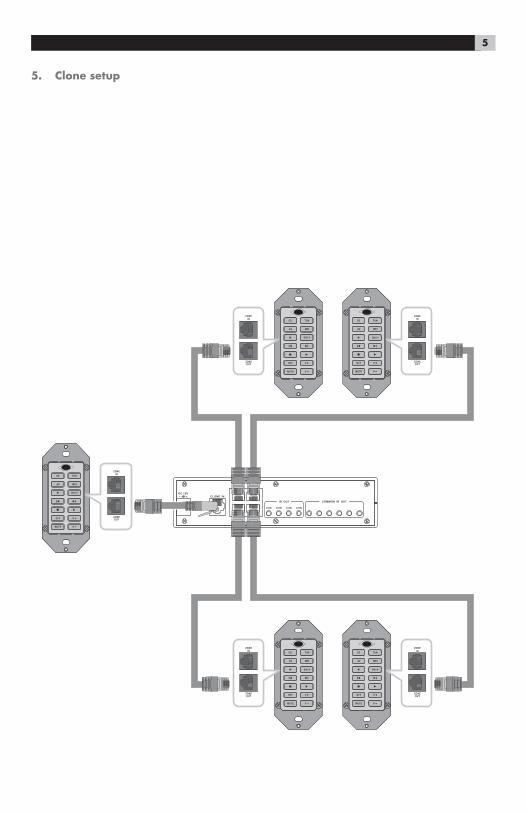
5. Clone setup
6 RKP-200/RHB-200
Contents1. RKP-200 Keypad 22. RHB-200 Connecting Hub 23. Connecting Keypads 34. Connecting RHB-200 45. Clone setup 5
Introduction .............................................................. 7Key Features 7
RKP-200 Overview ................................................... 7Device Buttons 7
Command Buttons 7
Multi-function Buttons 7
IR Sensor 7
Output Connector 7
Input Connector 7
DIP Switches 7
RESET Button 7
RHB-200 Overview ................................................... 7Zone LEDs 7
Power LED 7
Clone Button 7
+12V DC input 8
Clone Input 8
Zone Inputs 8
Zone IR Outputs 8
Common IR Outputs 8
Connecting the system ............................................... 8Cable selection 8Connecting Master Keypads 8
Connecting a Second Keypad 8
Mounting the Keypads 9Connecting the RHB-200 to a Rotel Receiver 9
Connecting the RHB-200 to Source Components 9
AC Power connection 9
Operating the Keypads .............................................10Selecting a component 10
Operating a CD Player 10
Operating a Tuner 10
Operating a DVD Player 10
Operating an MP3 Player 10
Backlighting 11
IR Sensor 11
Configuring the keypads ...........................................11Using the DIP switches 11
Disabling Backlighting 12
Disabling IR Sensor 12
Optional Device Buttons 12
Learning commands 13
Learning invisible layer commands 14
Programming a SMART Sequence 15
Programming a SMART Sequence with Invisible Layer Commands 16
Cloning 16
Resetting keypads 16
Changing buttons 16
7
IntroductionThe RKP-200 Keypad and RHB-200 Connecting Hub provide an integrated system that allows con-trol of Rotel multi-zone systems from wall mounted keypads in remote zones.
Key Features
• Programmed to operate Rotel multi-zone receiv-ers, DVD players, CD players, and AM/FM tuners.
• Learning function to teach the RKP-200 com-mands from other remotes. Multi-step SMART programming for automatic sequences.
• System allows control from up to four zones.
• Two identically programmed keypads can be installed in each zone.
• Built-in IR sensor allows each keypad to receive commands from a handheld remote.
• Backlighting for use in dark rooms whenever a button is pressed.
• Durable laser-etched buttons with permanent labels. Optional buttons provide alternate la-bels.
• Cloning feature for easy duplication of the entire command set from one RKP-200 to another.
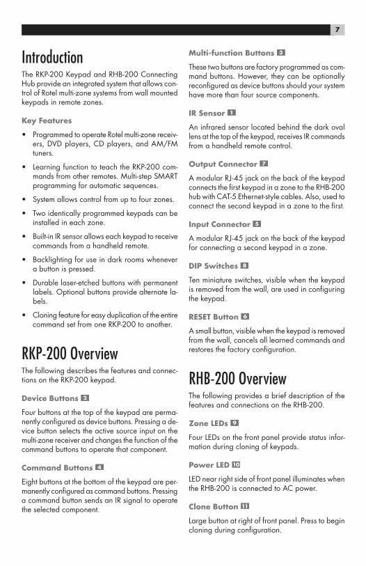
RKP-200 OverviewThe following describes the features and connec-tions on the RKP-200 keypad.
Device Buttons
Four buttons at the top of the keypad are perma-nently configured as device buttons. Pressing a de-vice button selects the active source input on the multi-zone receiver and changes the function of the command buttons to operate that component.
Command Buttons
Eight buttons at the bottom of the keypad are per-manently configured as command buttons. Pressing a command button sends an IR signal to operate the selected component.
Multi-function Buttons
These two buttons are factory programmed as com-mand buttons. However, they can be optionally reconfigured as device buttons should your system have more than four source components.
IR Sensor
An infrared sensor located behind the dark oval lens at the top of the keypad, receives IR commands from a handheld remote control.
Output Connector
A modular RJ-45 jack on the back of the keypad connects the first keypad in a zone to the RHB-200 hub with CAT-5 Ethernet-style cables. Also, used to connect the second keypad in a zone to the first.
Input Connector
A modular RJ-45 jack on the back of the keypad for connecting a second keypad in a zone.
DIP Switches
Ten miniature switches, visible when the keypad is removed from the wall, are used in configuring the keypad.
RESET Button
A small button, visible when the keypad is removed from the wall, cancels all learned commands and restores the factory configuration.
RHB-200 OverviewThe following provides a brief description of the features and connections on the RHB-200.
Zone LEDs
Four LEDs on the front panel provide status infor-mation during cloning of keypads.
Power LED
LED near right side of front panel illuminates when the RHB-200 is connected to AC power.
Clone Button
Large button at right of front panel. Press to begin cloning during configuration.
8 RKP-200/RHB-200
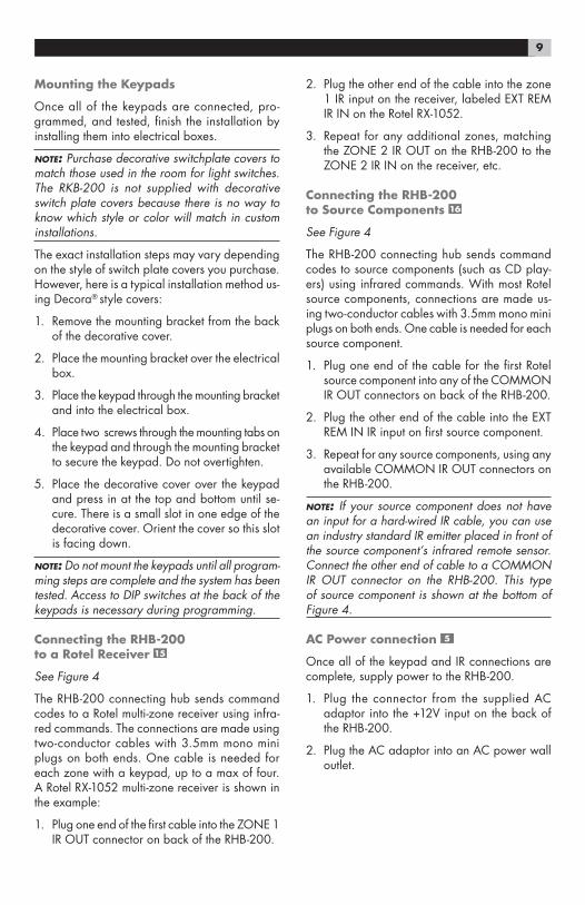
+12V DC input
The power connector receives +12V signal when AC power supply is plugged into a wall outlet.
Clone Input
RJ-45 modular jack accepts CAT-5 cable from keypad during cloning configuration.
Zone Inputs
Four RJ-45 modular jacks accept CAT-5 cables from keypads in up to four zones.
Zone IR Outputs
Four 3.5mm mini-jacks send IR signals to the zone IR inputs on a Rotel receiver.
Common IR Outputs
Six 3.5mm mini-jacks send IR signals to source components, either to a direct-wired connection (Rotel components) or to an IR emitter.
Connecting the systemMaster keypads in up to four remote zones con-nect to a centrally-located RHB-200 Connecting Hub using standard Category 5 Ethernet-style ca-bling and 8-pin RJ-45 modular plugs. A second keypad can be added in each of the four zones, if desired. The second keypad is connected to the master keypad in its zone and provides duplicate functions from a second location.
Cable selection
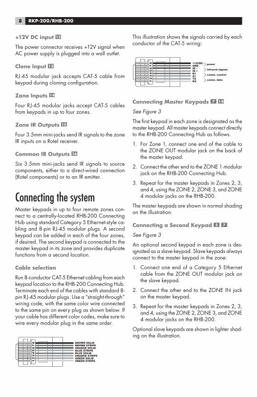
Run 8-conductor CAT-5 Ethernet cabling from each keypad location to the RHB-200 Connecting Hub. Terminate each end of the cables with standard 8-pin RJ-45 modular plugs. Use a “straight-through” wiring code, with the same color wire connected to the same pin on every plug as shown below. If your cable has different color codes, make sure to wire every modular plug in the same order.
12
34
56
78
GREEN STRIPEGREEN SOLIDORANGE STRIPEBLUE SOLIDBLUE STRIPEORANGE SOLIDBROWN STRIPEBROWN SOLID
This illustration shows the signals carried by each conductor of the CAT-5 wiring:
12
34
56
78
RX TX comm. dataA1B1IR +IR GND+12VDC
comm. control
infrared signals
power
Connecting Master Keypads
See Figure 3
The first keypad in each zone is designated as the master keypad. All master keypads connect directly to the RHB-200 Connecting Hub as follows.
1. For Zone 1, connect one end of the cable to the ZONE OUT modular jack on the back of the master keypad.
2. Connect the other end to the ZONE 1 modular jack on the RHB-200 Connecting Hub.
3. Repeat for the master keypads in Zones 2, 3, and 4, using the ZONE 2, ZONE 3, and ZONE 4 modular jacks on the RHB-200.
The master keypads are shown in normal shading on the illustration.
Connecting a Second Keypad
See Figure 3
An optional second keypad in each zone is des-ignated as a slave keypad. Slave keypads always connect to the master keypad in the zone:
1. Connect one end of a Category 5 Ethernet cable from the ZONE OUT modular jack on the slave keypad.
2. Connect the other end to the ZONE IN jack on the master keypad.
3. Repeat for the master keypads in Zones 2, 3, and 4, using the ZONE 2, ZONE 3, and ZONE 4 modular jacks on the RHB-200.
Optional slave keypads are shown in lighter shad-ing on the illustration.
9
Mounting the Keypads
Once all of the keypads are connected, pro-grammed, and tested, finish the installation by installing them into electrical boxes.
NOTE: Purchase decorative switchplate covers to match those used in the room for light switches. The RKB-200 is not supplied with decorative switch plate covers because there is no way to know which style or color will match in custom installations.
The exact installation steps may vary depending on the style of switch plate covers you purchase. However, here is a typical installation method us-ing Decora® style covers:
1. Remove the mounting bracket from the back of the decorative cover.
2. Place the mounting bracket over the electrical box.
3. Place the keypad through the mounting bracket and into the electrical box.
4. Place two screws through the mounting tabs on the keypad and through the mounting bracket to secure the keypad. Do not overtighten.
5. Place the decorative cover over the keypad and press in at the top and bottom until se-cure. There is a small slot in one edge of the decorative cover. Orient the cover so this slot is facing down.
NOTE: Do not mount the keypads until all program-ming steps are complete and the system has been tested. Access to DIP switches at the back of the keypads is necessary during programming.
Connecting the RHB-200 to a Rotel Receiver
See Figure 4
The RHB-200 connecting hub sends command codes to a Rotel multi-zone receiver using infra-red commands. The connections are made using two-conductor cables with 3.5mm mono mini plugs on both ends. One cable is needed for each zone with a keypad, up to a max of four. A Rotel RX-1052 multi-zone receiver is shown in the example:
1. Plug one end of the first cable into the ZONE 1 IR OUT connector on back of the RHB-200.
2. Plug the other end of the cable into the zone 1 IR input on the receiver, labeled EXT REM IR IN on the Rotel RX-1052.
3. Repeat for any additional zones, matching the ZONE 2 IR OUT on the RHB-200 to the ZONE 2 IR IN on the receiver, etc.
Connecting the RHB-200 to Source Components
See Figure 4
The RHB-200 connecting hub sends command codes to source components (such as CD play-ers) using infrared commands. With most Rotel source components, connections are made us-ing two-conductor cables with 3.5mm mono mini plugs on both ends. One cable is needed for each source component.
1. Plug one end of the cable for the first Rotel source component into any of the COMMON IR OUT connectors on back of the RHB-200.
2. Plug the other end of the cable into the EXT REM IN IR input on first source component.
3. Repeat for any source components, using any available COMMON IR OUT connectors on the RHB-200.
NOTE: If your source component does not have an input for a hard-wired IR cable, you can use an industry standard IR emitter placed in front of the source component’s infrared remote sensor. Connect the other end of cable to a COMMON IR OUT connector on the RHB-200. This type of source component is shown at the bottom of Figure 4.
AC Power connection
Once all of the keypad and IR connections are complete, supply power to the RHB-200.
1. Plug the connector from the supplied AC adaptor into the +12V input on the back of the RHB-200.
2. Plug the AC adaptor into an AC power wall outlet.
10 RKP-200/RHB-200
Operating the KeypadsThe keypads are preprogrammed to operate the Rotel RX-1052 multi-zone receiver and the follow-ing source components:
Rotel CD Players:RCD-1072 & RCC-1055
Rotel Tuner:RX-1052 built-in tuner
Rotel DVD Player:RDV-1092/RDV-1060
MP3 Players:Navipod and the most popular brands of por-table players
Although the keypads can be customized with learned commands, there is no need to do so when used with components listed above.
Selecting a component
Press one of the four standard device buttons ( , , , )to select that source component as the input for the zone. Once you have select-ed the component, use the 10 command buttons to operate the component you have selected as described below.
NOTE: If you choose to customize the keypads, two more buttons ( and ) can be used as additional device buttons.
Operating a CD Player
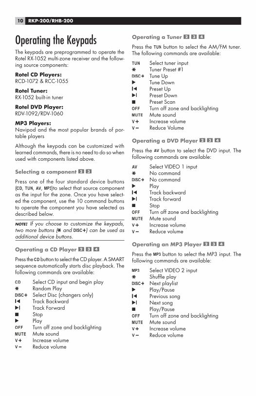
Press the button to select the CD player. A SMART sequence automatically starts disc playback. The following commands are available:
Select CD input and begin play Random Play
Select Disc (changers only) Track Backward Track Forward Stop Play
Turn off zone and backlighting Mute sound
Increase volume Reduce volume
Operating a Tuner
Press the button to select the AM/FM tuner. The following commands are available:
Select tuner input Tuner Preset #1
Tune Up Tune Down Preset Up Preset Down Preset Scan
Turn off zone and backlighting Mute sound
Increase volume Reduce Volume
Operating a DVD Player
Press the button to select the DVD input. The following commands are available:
Select VIDEO 1 input No command
No command Play Track backward Track forward Stop
Turn off zone and backlighting Mute sound
Increase volume Reduce volume
Operating an MP3 Player
Press the button to select the MP3 input. The following commands are available:
Select VIDEO 2 input Shuffle play
Next playlist Play/Pause Previous song Next song Play/Pause
Turn off zone and backlighting Mute sound
Increase volume Reduce volume
11
Backlighting
As delivered from the factory, the keypads have automatic backlighting for the device buttons and the button.
When a device button is pressed, the backlighting for that button remains lit to indicate the currently selected device.
The backlighting for the button remains on when the sound is muted. The backlighting turns off when the button is pressed again or when muting is cancelled by pressing the or
buttons.
All backlighting is turned off when the but-ton is pressed and remains off until a device but-ton is pressed.
NOTE: The backlighting feature can be permanently disabled during configuration of the keypads.
IR Sensor
An infrared sensor is located behind the dark oval lens at the top of the keypad. This sensor receives IR commands from a handheld remote control aimed at the keypad.
IR commands received by the IR sensor do not change the backlighting on the keypad. For ex-ample, a MUTE command received from a hand-held remote will not light the MUTE button on the keypad.
MUTE: The IR sensor can be disabled during con-figuration of the keypads. Generally, the sensor of a second keypad in a zone should be disabled if there is a chance of IR signals reaching both keypads simultaneously.
Configuring the keypadsWith the default factory configuration, the keypads are ready to use in a system with Rotel compo-nents as described in the Operating the Keypads section of the manual. However, the keypads can be customized in several ways during setup. Op-tions include:
• Learning commands from handheld remote controls in place of the existing commands.
• Combining the commands in a SMART sequence that is sent whenever a device is selected.
• Using two additional buttons as device keys, for a total of six available source components.
• Disabling the infrared sensor on the front of the keypad.
• Disabling the backlighting.
• Resetting the keypad to its default factory con-figuration.
• Replacing the standard button labels with op-tional labels.
This section of the manual provides instructions for each of these configuration steps.
NOTE: An additional customizing feature is Cloning, which allows quick transfer of learned commands and SMART sequences to additional keypads. Cloning is covered in a later section of the manual.
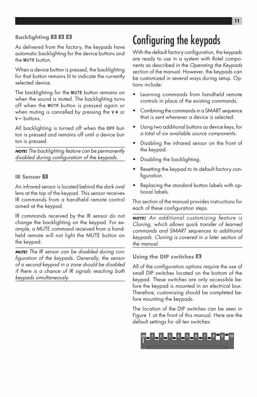
Using the DIP switches
All of the configuration options require the use of small DIP switches located on the bottom of the keypad. These switches are only accessible be-fore the keypad is mounted in an electrical box. Therefore, customizing should be completed be-fore mounting the keypads.
The location of the DIP switches can be seen in Figure 1 at the front of this manual. Here are the default settings for all ten switches:
12 RKP-200/RHB-200
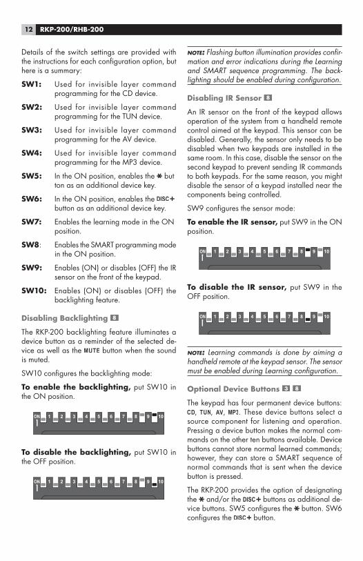
NOTE: Flashing button illumination provides confir-mation and error indications during the Learning and SMART sequence programming. The back-lighting should be enabled during configuration.
Disabling IR Sensor
An IR sensor on the front of the keypad allows operation of the system from a handheld remote control aimed at the keypad. This sensor can be disabled. Generally, the sensor only needs to be disabled when two keypads are installed in the same room. In this case, disable the sensor on the second keypad to prevent sending IR commands to both keypads. For the same reason, you might disable the sensor of a keypad installed near the components being controlled.
SW9 configures the sensor mode:
To enable the IR sensor, put SW9 in the ON position.
To disable the IR sensor, put SW9 in the OFF position.
NOTE: Learning commands is done by aiming a handheld remote at the keypad sensor. The sensor must be enabled during Learning configuration.
Optional Device Buttons
The keypad has four permanent device buttons:, , , . These device buttons select a
source component for listening and operation. Pressing a device button makes the normal com-mands on the other ten buttons available. Device buttons cannot store normal learned commands; however, they can store a SMART sequence of normal commands that is sent when the device button is pressed.
The RKP-200 provides the option of designating the and/or the buttons as additional de-vice buttons. SW5 configures the button. SW6 configures the button.
Details of the switch settings are provided with the instructions for each configuration option, but here is a summary:
SW1: Used for invisible layer command programming for the CD device.
SW2: Used for invisible layer command programming for the TUN device.
SW3: Used for invisible layer command programming for the AV device.
SW4: Used for invisible layer command programming for the MP3 device.
SW5: In the ON position, enables the but ton as an additional device key.
SW6: In the ON position, enables the button as an additional device key.
SW7: Enables the learning mode in the ON position.
SW8: Enables the SMART programming mode in the ON position.
SW9: Enables (ON) or disables (OFF) the IR sensor on the front of the keypad.
SW10: Enables (ON) or disables (OFF) the backlighting feature.
Disabling Backlighting
The RKP-200 backlighting feature illuminates a device button as a reminder of the selected de-vice as well as the button when the sound is muted.
SW10 configures the backlighting mode:
To enable the backlighting, put SW10 in the ON position.
To disable the backlighting, put SW10 in the OFF position.
13
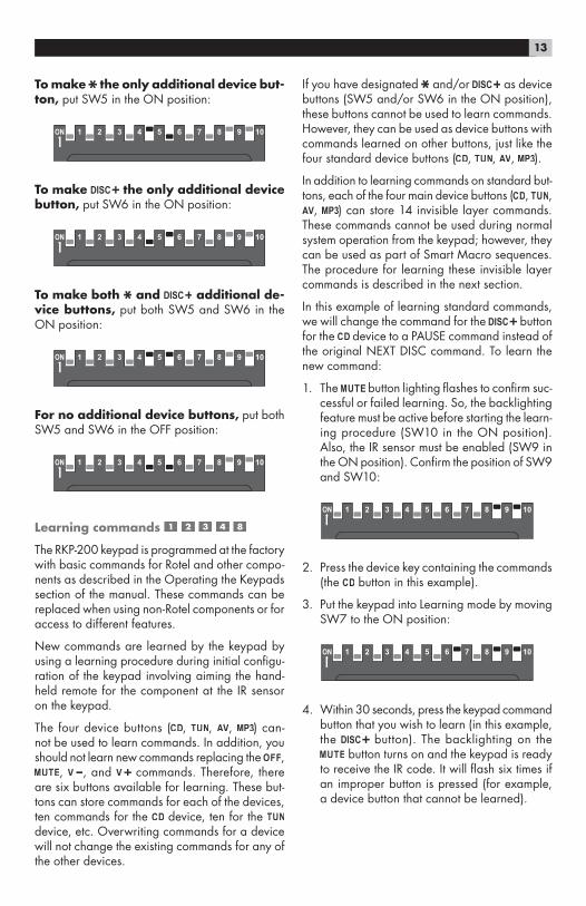
To make the only additional device but-ton, put SW5 in the ON position:
To make the only additional device button, put SW6 in the ON position:
To make both and additional de-vice buttons, put both SW5 and SW6 in the ON position:
For no additional device buttons, put both SW5 and SW6 in the OFF position:
Learning commands
The RKP-200 keypad is programmed at the factory with basic commands for Rotel and other compo-nents as described in the Operating the Keypads section of the manual. These commands can be replaced when using non-Rotel components or for access to different features.
New commands are learned by the keypad by using a learning procedure during initial configu-ration of the keypad involving aiming the hand-held remote for the component at the IR sensor on the keypad.
The four device buttons ( , , , ) can-not be used to learn commands. In addition, you should not learn new commands replacing the ,
, , and commands. Therefore, there are six buttons available for learning. These but-tons can store commands for each of the devices, ten commands for the device, ten for the device, etc. Overwriting commands for a device will not change the existing commands for any of the other devices.
If you have designated and/or as device buttons (SW5 and/or SW6 in the ON position), these buttons cannot be used to learn commands. However, they can be used as device buttons with commands learned on other buttons, just like the four standard device buttons ( , , , ).
In addition to learning commands on standard but-tons, each of the four main device buttons ( , ,
, ) can store 14 invisible layer commands. These commands cannot be used during normal system operation from the keypad; however, they can be used as part of Smart Macro sequences. The procedure for learning these invisible layer commands is described in the next section.
In this example of learning standard commands, we will change the command for the button for the device to a PAUSE command instead of the original NEXT DISC command. To learn the new command:
1. The button lighting flashes to confirm suc-cessful or failed learning. So, the backlighting feature must be active before starting the learn-ing procedure (SW10 in the ON position). Also, the IR sensor must be enabled (SW9 in the ON position). Confirm the position of SW9 and SW10:
2. Press the device key containing the commands (the button in this example).
3. Put the keypad into Learning mode by moving SW7 to the ON position:
4. Within 30 seconds, press the keypad command button that you wish to learn (in this example, the button). The backlighting on the
button turns on and the keypad is ready to receive the IR code. It will flash six times if an improper button is pressed (for example, a device button that cannot be learned).
14 RKP-200/RHB-200
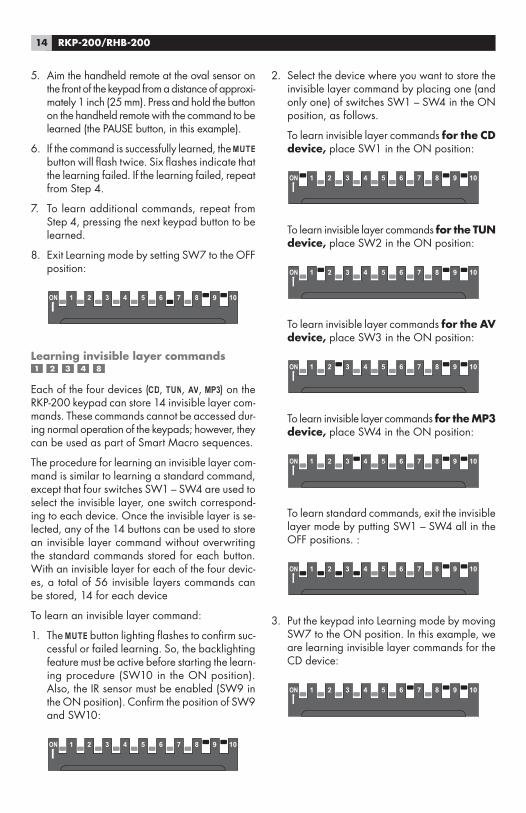
5. Aim the handheld remote at the oval sensor on the front of the keypad from a distance of approxi-mately 1 inch (25 mm). Press and hold the button on the handheld remote with the command to be learned (the PAUSE button, in this example).
6. If the command is successfully learned, the button will flash twice. Six flashes indicate that the learning failed. If the learning failed, repeat from Step 4.
7. To learn additional commands, repeat from Step 4, pressing the next keypad button to be learned.
8. Exit Learning mode by setting SW7 to the OFF position:
Learning invisible layer commands
Each of the four devices ( , , , ) on the RKP-200 keypad can store 14 invisible layer com-mands. These commands cannot be accessed dur-ing normal operation of the keypads; however, they can be used as part of Smart Macro sequences.
The procedure for learning an invisible layer com-mand is similar to learning a standard command, except that four switches SW1 – SW4 are used to select the invisible layer, one switch correspond-ing to each device. Once the invisible layer is se-lected, any of the 14 buttons can be used to store an invisible layer command without overwriting the standard commands stored for each button. With an invisible layer for each of the four devic-es, a total of 56 invisible layers commands can be stored, 14 for each device
To learn an invisible layer command:
1. The button lighting flashes to confirm suc-cessful or failed learning. So, the backlighting feature must be active before starting the learn-ing procedure (SW10 in the ON position). Also, the IR sensor must be enabled (SW9 in the ON position). Confirm the position of SW9 and SW10:
2. Select the device where you want to store the invisible layer command by placing one (and only one) of switches SW1 – SW4 in the ON position, as follows.
To learn invisible layer commands for the CD device, place SW1 in the ON position:
To learn invisible layer commands for the TUN device, place SW2 in the ON position:
To learn invisible layer commands for the AV device, place SW3 in the ON position:
To learn invisible layer commands for the MP3 device, place SW4 in the ON position:
To learn standard commands, exit the invisible layer mode by putting SW1 – SW4 all in the OFF positions. :
3. Put the keypad into Learning mode by moving SW7 to the ON position. In this example, we are learning invisible layer commands for the CD device:
15
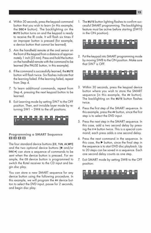
4. Within 30 seconds, press the keypad command button that you wish to learn (in this example, the button). The backlighting on the
button turns on and the keypad is ready to receive the IR code. It will flash six times if an improper button is pressed (for example, a device button that cannot be learned).
5. Aim the handheld remote at the oval sensor on the front of the keypad from a distance of approxi-mately 1 inch (25 mm). Press and hold the button on the handheld remote with the command to be learned (the PAUSE button, in this example).
6. If the command is successfully learned, the button will flash twice. Six flashes indicate that the learning failed. If the learning failed, repeat from Step 4.
7. To learn additional commands, repeat from Step 4, pressing the next keypad button to be learned.
8. Exit Learning mode by setting SW7 to the OFF position. Then, exit invisible layer mode by re-turning SW1 – SW4 to the off positions.
Programming a SMART Sequence
The four standard device buttons ( , , , ) and the two optional device buttons ( and/or
) can store a sequence of commands to be sent when the device button is pressed. For ex-ample, the device button is programmed to switch the Rotel receiver to the CD input and be-gin disc play.
You can store a new SMART sequence for any device button using the following procedure. In this example, we will program the device but-ton to select the DVD input, pause for 2 seconds, and begin disc play.
1. The button lighting flashes to confirm suc-cessful SMART programming. The backlighting feature must be active before starting (SW10 in the ON position).
2. Put the keypad into SMART programming mode by moving SW8 to the ON position. Make sure that SW7 is OFF.
3. Within 30 seconds, press the keypad device button where you wish to store the SMART sequence (in this example, the button). The backlighting on the button flashes twice.
4. Press the first step of the SMART sequence. In this example, press the button, since the first step is to select the DVD input.
5. Press the next step in the SMART sequence. In this case, add a two second delay by press-ing the button twice. This is a special com-mand; each press adds a one second delay.
6. Press the next command in the sequence. In this case, the button, since the final step in the sequence is to start DVD disc playback. Up to 20 steps can be saved in a sequence. Each one second delay counts as one step.
7. Exit SMART mode by setting SW8 to the OFF position:
16 RKP-200/RHB-200
Programming a SMART Sequence with Invisible Layer Commands
To include invisible layer commands in a SMART sequence, substitute the following steps for Step 4 in the preceding instructions:
• Put SW1, SW2, SW3, or SW4 in the ON posi-tion to select the invisible layer where the de-sired command is stored:
• Press the invisible layer command button.
• Return the SW1 – SW4 switch to the OFF po-sition to exit invisible layer mode.
Cloning
Once you have completed the learning and SMART sequence programming for one keypad, it is easy to transfer that programming to all of the keypads connected to the RHB-200 with a proce-dure called cloning.
To clone a keypad:
1. With the RHB-200 disconnected from the AC wall power, connect the ZONE OUT connec-tor of the programmed keypad to the CLONE IN modular jack on the back of the RHB-200 using a CAT 5 cable.
2. Make sure that all keypads to be programmed are connected properly as shown in Figure 5. You can program two keypads in a single zone as shown by light shaded keypads in the illus-tration.
NOTE: Keypads in the remote zones must not be in Learning or SMART configuration mode.
3. Power on the RHB-200 by connecting it to the AC power source. The four Zone LEDs on the front of the RHB-200 flash green once. The
LED on the keypad being cloned flashes once.
4. Press the large CLONE button on the front panel of the RHB-200. The cloning process begins in sequence, starting with the first key-
pad in ZONE 1. While this keypad is receiv-ing cloned data, the ZONE 1 LED on the front of the RHB-200 flashes red. When the cloning of the first keypad is complete, the LED glows solid red. The cloning process then continues to the second keypad in ZONE 1 (if it exists). The LED flashes green during the cloning and glows solid green when the cloning is com-plete.
5. Step 5 is then repeated automatically for Zone 2, Zone 3, and Zone 4 as necessary. The entire cloning process can take up to 10 minutes.
6. If an error occurs, all four LEDs on the RHB-200 flash green six times and the DEVICE buttons on the zone keypads flash on for one second.
Resetting keypads
Should you want to reset a keypad to its original factory programming, use a small pointed ob-ject to press the reset button on the side of the keypad. This erases all learned commands and SMART sequences.
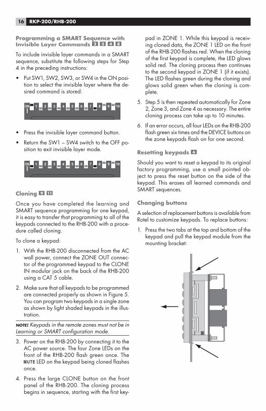
Changing buttons
A selection of replacement buttons is available from Rotel to customize keypads. To replace buttons:
1. Press the two tabs at the top and bottom of the keypad and pull the keypad module from the mounting bracket:
17
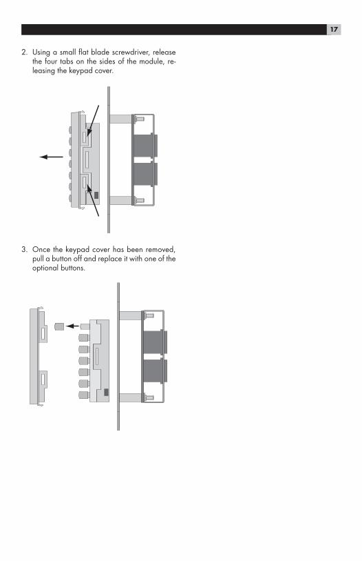
2. Using a small flat blade screwdriver, release the four tabs on the sides of the module, re-leasing the keypad cover.
3. Once the keypad cover has been removed, pull a button off and replace it with one of the optional buttons.

The Rotel Co. Ltd.10-10 Shinsen-Cho
Shibuya-KuTokyo 150-0045
JapanPhone: +81 3-5458-5325 Fax: +81 3-5458-5310
Rotel of America54 Concord Street
North Reading, MA 01864-2699USA
Phone: +1 978-664-3820Fax: +1 978-664-4109
Rotel EuropeDale Road
Worthing, West Sussex BN11 2BHEngland
Phone: +44 (0)1903 221600Fax: +44 (0)1903 221525
Rotel DeutschlandKleine Heide 12
D-33790 Halle/Westf.Germany
Phone: +49 05201-87170Fax: +49 05201-73370
www.rotel.com
082 OM RKP-200/RHB-200 ENG 112105