Embed Size (px)
Citation preview
Mauretania 1907 © Stephen Carey Page 1 of 36
RMS MAURETANIA 1907
OWNERS: CUNARD LINE LTD
BUILDERS: SWAN, HUNTER & WIGHAM RICHARDSON, NEWCASTLE ON TYNE
COLD STARTING

Mauretania 1907 © Stephen Carey Page 2 of 36
STARTING RMS MAURETANIA (from cold)
1 Overview of machinery spaces 1.1 Boiler rooms
Mauretania is (or was) a quadruple screw Cunard liner fitted with 2 single-ended and 23 double-ended boilers, operating at 195lb/in2. These boilers are arranged six in 3 boiler rooms (4,3 & 2; note that Cunard numbers forward to aft compared to White Star which numbers aft to forward), and five in No1 Boiler Room (the foremost one) where the fine lines of the ship only allow 2 abreast at the forward end of this boiler room.
No1 Boiler Room also houses the two single ended boilers used for hotel services and auxiliary supplies in port. The double-ended boilers are fired for transatlantic passages up to full speed and primarily used for main propulsion.
Combustion air for the boilers is provided by forced draught fans, so for cold starting these have to be run up on the shore electric supply before firing the boilers.
1.2 Coal bunkers
Coal bunkers are provided either side of the stokehold furnaces in each boiler room to enable a ready supply of coal for the trimmers and firemen to stoke the boilers. These bunkers form the double side of the ship through all the boiler rooms (unlike Titanic which has transverse bunkers either side of the transverse watertight bulkheads). These were later converted to fuel oil tanks when the liner was converted to oil firing.
Ash chutes are provided to discharge ash from the furnace bottoms overboard at regular intervals to keep the stokehold clear of ash whilst at sea. In port ash hoists are used to dispose of the ash to shore facilities.
The main steam pipes run the length of the boiler rooms to the bulkhead stops in the centre engineroom for distribution to the engines and auxiliaries.
1.3 Propulsion engines
There are two high-pressure turbines situated in the wing watertight turbine rooms, aft of Boiler Room No4. Steam from the main steam piping is admitted to the high-pressure turbines, which then exhaust into the ahead low-pressure turbines situated in the centre engineroom.
Exhaust steam from the low-pressure turbine is directed to the vacuum condensers, situated in a further watertight compartment aft of the turbine room, where it is condensed into feed water and pumped back into the boilers.
Manoeuvring from ahead to astern is carried out on the LP ahead and astern turbines, the hp turbines playing no part in the astern operations. Steam is directed either ahead or astern by means of a large manoeuvring valve driven by a steam driven gear. The main exhaust sluice valve for directing steam from the hp turbine to the condensers direct (i.e. bypassing the lp turbines) is electrically driven. This bypassing is only used in an emergency, as it is extremely inefficient to exhaust the hp turbines straight into the condensers.
Regulating valves driven by worm and quadrant gear via spindles operated from the starting and manoeuvring platform, admit steam to the engines as required by the telegraph orders.

Mauretania 1907 © Stephen Carey Page 3 of 36
1.4 Electrical power generation
1.4.1 Main generating sets
The vessel is fitted with four 375kW 110Vdc main turbo-generators driven by Parsons steam turbine prime movers. These sets are situated two to a watertight room aft of the condenser watertight room, separated by a centreline watertight bulkhead, ensuring maximum redundancy from damage. As the vessel is not fitted with either auxiliary or emergency generators, it is assumed that the watertight arrangements of these compartments plus the huge redundancy in steam production would ensure the reliability of the electrical generating supply.
Steam at a pressure of 195lb/in2 is fed to the turbines and exhaust steam is directed in port or at start up to the auxiliary condensers. At sea the exhaust steam is directed to the surface and/or direct contact feed heaters to extract the remaining energy from the exhaust steam and deliver it to the feed heating system. This configuration gives a total installed electrical power of 1.5MWdc, with three sets covering the full steaming load with one in stand-by.
2 Going on board
Figure 1: Dark and quiet alongside
Here’s our ship sitting quietly alongside on shore power awaiting our arrival to start her up. We are not doing this alone (that’s a bit too much for two engineers on a ship of this vintage) so we will assume there are firemen, trimmers and engineers on hand to help wherever we need it.
Note: A modern motorship such as a container ship, super tanker or bulk carrier can indeed be started up from cold by one person – times change…
Mauretania 1907 © Stephen Carey Page 4 of 36
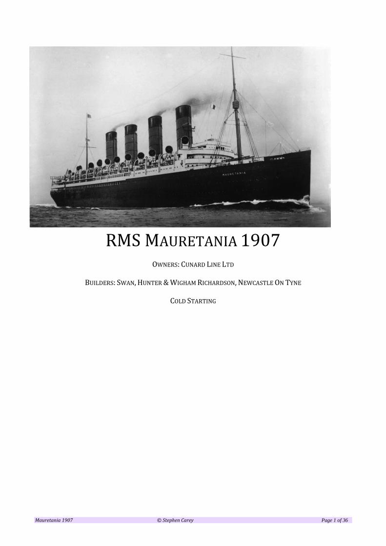
Mauretania is different from a lot of her contemporaries in that her engineers’ accommodation is not placed round the engineroom in the bowels of the ship, but up aloft on the Shelter Deck. This gives cabins with a nice view of the sea, and a short promenade deck for taking the air. Not before time!
Figure 2: Engineers' Accommodation
We even have our own gangway, which we and the other engineroom staff can use. We turn and walk forward past the 2nd Class entrance and the Firemen’s entrance to the Engineers’ entrance, where we go through the door, walk inboard and aft to the cabins at the far end. Choose one and stow your gear, get changed into a boiler suit, pick up your “steaming bats” (Naval terminology for work boots) and your 2nd best cap (the one covered in oil, grease and coal dust) and head out to the changing room. Dressed like this we are not allowed (when passengers are aboard) to exit back out of the accommodation entrance in case we frighten the passengers (who we share the promenade with), so will head off down below via the engineers’ changing room, shown as the “Engineers Lavy” in the plan above. Here we put our boots on, as we are not allowed in our accommodation in “clarty byuts” (she’s a Geordie ship…).
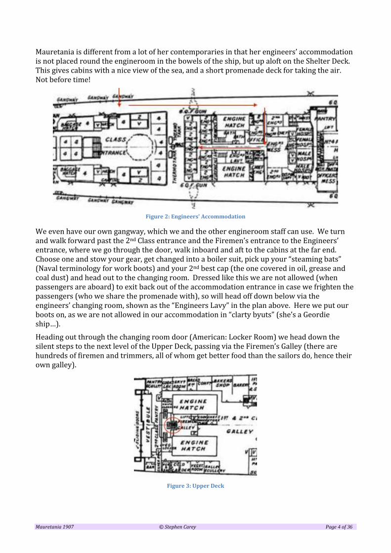
Heading out through the changing room door (American: Locker Room) we head down the silent steps to the next level of the Upper Deck, passing via the Firemen’s Galley (there are hundreds of firemen and trimmers, all of whom get better food than the sailors do, hence their own galley).
Figure 3: Upper Deck

Mauretania 1907 © Stephen Carey Page 5 of 36
We have to watch our step as the emergency lighting from the shore power is only lighting the head and foot of the stairs. Keep on going down to the next level, which is the Main Deck, where we pass by the Firemen’s Dining Room.
Figure 4: Main Deck
Here we can pass out into the engineroom through one of the sets of double doors shown on the above plan, which will get us into the upper levels of the main engine room, where we can head down the engineroom ladders into the centre engineroom and thence to the bottom plates. It’s quiet in here at the moment, and a bit dimly lit as we are only on transitional lighting. It’s quite chilly too, but that will change once we have a few boilers going. As there are no diesel generators on this ship, we need steam to start up the main generators, and for this we need to head forward through the boiler rooms to Boiler Room 1, as far as we can go.
Heading through the watertight door at the forward bulkhead of the centre engineroom, we enter Boiler Room 4 (Cunard numbered their boiler rooms from forward to aft, in the opposite direction to White Star Line). Here we are in a huge space smelling of coal dust and sulphurous products of combustion – rather like in a steam engine-shed on a preserved railway. In this boiler room are 6 double-ended Scotch boilers, as there are in the next two boiler rooms Nos 3 and 2. Passing through the last WT door into Boiler Room 1, we find there are only 5 double ended boilers here, owing to the finer lines at the bow. Right up forward are two more single-ended Scotch boilers used for hotel services in port, so these are the ones we will start up in the first place in order to get steam on for a generator start.

Mauretania 1907 © Stephen Carey Page 6 of 36
Figure 5: Boiler Room 1
3 Firing up the boilers
Our first task therefore is to gather a Leading Fireman plus a handful of firemen (sometimes called Stokers) and trimmers in order to get them to start firing the number of boilers required.
Note: The Leading Fireman directs the stokehold crew in their duties, keeps an eye on the fires, observes the orders on the stokehold telegraphs and generally cracks the whip over the stokehold crew. These are hard men: tough, probably violent, hard drinking, hard working, uneducated and often difficult to handle. The Fireman’s job is to keep the furnaces stoked with coal, trim the fires for efficient burning of fuel, draw fires for cleaning, and obey the orders of the Leading Fireman. They are respectful of the engineers however, which is a relief – some scary guys here, and there are hundreds of them! They don’t mess with the Leading Fireman either, who is harder than they are. The Trimmers are similar and are the lowest grade of engineroom crew. They may aspire to being firemen and even Lead Fireman over the years. Their job is to shovel coal and ash and help out with oiling round the machinery – coal from the bunkers is shovelled to the stokehold floor, ash from the ash pits is shovelled to the ash chutes and lifts. It’s a hard, backbreaking, hot and dirty job for sure, though their watches of 4-on, 8-off are better than the deck crew who do 6-on, 6-off. They are also better paid and get better food than the sailors, who are still steeped in sailing ship days. The Engineers are also better paid than the Deck Officers, have better food (unless the deck officers are eating in the passenger accommodation like the Captain may do) and have watches of 4-on, 8-off. The Deck Officers tend to work RN watches (Cunard officers all had a Master’s Ticket in Sail), which include Dog Watches of two hours each in order to cycle the times they are on watch.
These ships carried 29 Engineering Officers including electrical and refrigeration engineers, boilermakers, plumbers and the Chief Engineer’s Writer (Clerk). To tend the boilers she had – whilst coal fired – 337 firemen and trimmers, making a department of some 366, all under the aegis of the Chief Engineer. In contrast the Deck Department consisted of 70 officers and crew (60-odd of whom were crew, less than ten were officers), and the Purser’s department 376, a grand total of 812 officers and crew.
In modern ships, the 2nd Engineer takes the 4-8, the 3rd Engineer the 12-4 and the Chief Engineer the 8-12, though his watch is delegated by him to the 4th Engineer as it is within normal daylight hours. A modern VLCC (super tanker) carries a Chief, 2nd, two 3rd and two 4th engineers plus – if

Mauretania 1907 © Stephen Carey Page 7 of 36
they are lucky – a couple of Junior Engineers and cadets. Most motor ships carry only four engineers.
For the Mauretania and Lusitania there were many engineers required to work what was essentially a manual ship; you and I are relatively junior – I am an Assistant-Third and you are a Fiver (one of many), so you call me “Third” or “Sir” if you want to be sycophantic… First names were not often used in those days, the hierarchy being fairly rigid. You would never call the 2nd or Chief Engineer by their first names – not a good career move!
Under the firm guidance of the Lead Firemen, the firemen are set to work in the required boiler rooms to lay fires in sufficient boilers to provide enough steam for the generators.
This is easier said than done – first the trimmers start chipping away at the bunker to release the coal so that they can shovel it into wheelbarrows and deliver it to the stokehold in front of the grates. Meanwhile the firemen are “coaling the bars” in order to give a bed of coal about 4” deep that won’t burn through once it’s lit. This will take some time, and already we are getting coal dust up our noses, and on our hands and faces. We will grab hold of an electrician and send him up to start a stokehold fan off the shore supply. We can’t start too many of these as they are quite high consumption and shore power is normally quite limited – we’ll go up with him to get out of the way of the firemen.
Figure 6: Above the boilers and machinery spaces to the skylights (public domain)
Cunard used Forced Draught (FD) fans on their boilers, as opposed to Natural or Induced Draught on White Star ships. This means we can’t start a boiler without an FD fan on, so we really need the shore power. The fans are located above the boilers, with their intakes trunked from the ventilators on deck and the discharge trunked to the boiler registers for primary and secondary air. We go to the starter for the fan for our boiler room and start it up; it’s a big fan and quite noisy once it gets going. We’ll add to the racket by starting a ventilation fan for the stokehold at the same time. Note: Primary Air is fed via the trunking under the grate area to give a flow of air through the firebed. Secondary Air is admitted via the trunking to above the firebed via the fire door registers in order to supply excess air for complete burning of the coal and to keep down black smoke. The black smoke you see from coal fired (and some improperly fired oil-fired ships) is too much fuel

Mauretania 1907 © Stephen Carey Page 8 of 36
and not enough air, whereas too much air causes white smoke. A coal-fired ship is difficult to fire cleanly during manoeuvring owing to the lag in response to fuel application and burning, especially with over 20 boilers all fired at the same time. There is no real excuse for smoke with oil firing, though it can still happen when sudden demand is made on the propulsion plant or when lighting up from cold. Both Primary and Secondary air supply is controlled via dampers in the trunking and registers; it’s a skilled job, firing a coal-fired boiler. Opening the fire door to shovel in coal reduces the secondary air whilst the door is open, and the dust from the coal thrown into the furnace gives black smoke at the funnel. This clears once the door is shut and the air adjusted, but with double ended boilers this cycle is continuous during manoeuvring.
Figure 7: Primary and Secondary air
Once the bars are coaled and the stokehold fan is keeping the dust down a bit, pieces of wood are put on a shovel and launched into the middle of the firebed, along with twists of newspaper to get the fire to hold long enough to light the coal. This requires some expertise, so we watch what they are doing, without getting in the way. An elbow in the face from one of these guys “accidentally on purpose” will not improve our day. Once the kindling is laid, an oily rag (plenty of those to hand) or cotton waste is placed on a shovel, some paraffin is poured on it and a candle lights it up. Once it is burning nicely, the fireman hefts the shovel and throws the burning rag right onto his pile of kindling, which will start to burn almost immediately. Deftly, he slings a couple of shovels-full of coal onto the burning kindling without disturbing it (you or I would probably put the fire out with a clumsily launched shovel-full). Allowing the air to enter the underside of the grate using the dampers, the flame is fed with air through the coal bed. Once the pile of coal has lit, it will in turn light the coal adjacent to it until eventually the whole firebed is starting to light up – the firemen help by moving burning coal from place to place to ensure the whole bed is alight. If the fire burns through in any particular place, the draft will blow through the hole in the bed, thereby starving the rest of the bed (white smoke), so the firemen have to keep an eye out for this and deposit coal on the places where the fire looks as if it will burn through. If the bed is too heavy, the air will not get through and the fire will not be as hot, resulting in more black smoke at the funnels. Generally, a heavy bed will show a red colour and black smoke, holes in the bed will show white heat and white smoke at the funnels. A proper fire is a straw colour with the whole bed glowing and no smoke. Once the bed is like this, and the ship is well underway, “light firing” takes place where the furnaces are fed little and often. A small shovelful of small coal thrown in to the furnace will disappear almost immediately and give a boost to the heating effect, rather than shovelling large lumps too much at a time. This is skilled work, but these men are the pick of the fleet in such a prestigious liner. As are you and I incidentally…

Mauretania 1907 © Stephen Carey Page 9 of 36
The boiler room is starting to smell of smoke and sulphurous products of combustion – rather nice to steam engineers like us. It’s getting quite warm in here, so we’ll stay until the pressure gauge starts to move. First though we will climb up the ladders to the top of the boilers and open the stop valves on our boilers. This will allow a passage from the boilers to the main bulkhead stop valves on the watertight bulkhead aft of Boiler Room 4, and allow us to bring up the lines to temperature by draining them in each space. As you can see from the drawing below, there are a lot of steam lines to warm through before we can get steam into the engineroom.
Figure 8: boiler rooms and steam piping (insert better scan)
Once lit, the dampers adjust the boiler draft and the fires start to heat the water in the fire-tube boilers. Once the boiler pressure starts to rise, any vents open at the top of the boiler that are open to dispel air will be closed once steam issues from them. The boiler stop valves are “screw-down” type often with a further non-return valve close to where they join the main line, meaning that a certain differential in pressure between one boiler and another will close the valve on the lower pressure boiler; once the lower pressure one comes up to the same or higher pressure, the NR valve will open.

Mauretania 1907 © Stephen Carey Page 10 of 36
Figure 9: Section through boiler room (Shipbuilder)
In the section above can be seen the Engineers’ cabin deck (Shelter Deck) and the route down to the boiler tops via ladders. The FD fans on the Lower Deck and their trunking can be seen above the steam piping from the boilers into the central main steam piping. The wing bunkers are clearly seen, as are the fire doors for each boiler. The line near the bottom of the boiler shell shows the level of the floorplates, which are sealed to stop ash from dropping into the piping space below. Mauretania’s characteristic ventilators can be seen with ducting to the boat deck, which are often used to differentiate her from her sister Lusitania. The central smoke uptakes to the funnel are shown with their connections to each boiler.
Note: Water-tube boilers are much more efficient and faster starting than fire-tube, but weren’t well tried and proven in the early part of the century, mainly being tested in small warships. It would take around 7 – 12 hours to warm through and start to raise sufficient steam. Raising
Mauretania 1907 © Stephen Carey Page 11 of 36
steam too quickly in a cold boiler can lead to thermal stress which is not good for the boiler longevity and could even cause cracking and rupture, especially on riveted boilers.
No1 boiler room was used in port as it the single-ended boilers in it and can feed steam to both the emergency and the main generators whilst keeping the main lines warmed through. For main propulsion at sea the main double-ended boilers are used, with the single-ended boiler fires in Boiler Room 1 drawn and re-laid ready for lighting in the next port. Owing to short port turnarounds, the main boilers would remain lit with fires banked ready for a (reasonably) quick start without using too much coal.
Once we have a main generator going, the number of boilers required for sailing are also laid and lit, and we will get back to this later.
We can now leave the “cosy” boiler room and exit back through the watertight door back through the other still cold boiler rooms and back into the centre engine room - still a bit chilly in here. We will check out the auxiliary condenser and its equipment ready for starting the generators once the boilers are up to pressure.
The generators are available for starting with a steam pressure of 185lb/in2, so this will take some hours to achieve. We’ll go for a cup of tea first, and put our feet up out of sight of the other engineers, or maybe even turn in for a few hours.
We go off watch, having made sure everything is OK down below, leaving another engineer to keep an eye on the stokehold up forward. Other engineers are busy instructing the firemen in the other boiler rooms to start coaling the bars ready for the upcoming transatlantic passage. Once they have done this, they can also “knock off” and wait for main power to come on.
We are dozing in our cabins, and get a “shake” to tell us it’s now 12 hours on, and that we have around 190lb/in2 at the main stops to the main steam lines into the enginerooms. You will remember that we left the main stop valves of the single-ended boilers open to the main steam pipe during firing in order to bring up the piping temperature to that of these first boilers lit, such that the piping and valve drains clear the lines of condensate, which can damage reciprocating and turbine machinery. These drain lines are situated at intervals and incorporate a “steam trap” which automatically drains any water that condenses in the lines. Steam traps (Figure 10 & Figure 11) are used on all lines that carry steam throughout the vessel, and often have a bypass line to manually drain a lot of condensate out of the line a bit faster than the steam trap will. Once the line is up to pressure, water cannot exist in the line to any great degree, and the steam traps will handle any that collects in the drain pots. The steam traps are normally connected to a drain line, which transports the condensate to a drain tank where it can be reused. Feedwater and condensate are the “liquid gold” of a steamship, and every effort is made not to waste this valuable commodity.

Mauretania 1907 © Stephen Carey Page 12 of 36
Figure 10: Steam trap with connection to drain lines - © Spirax-Sarco
Figure 11: Steam trap in action - © Spirax-Sarco
By this time, all remaining boilers have their bars coaled and with the main stops closed until main power is available and more steam is needed for propulsion.
4 Starting the generators
Figure 12: Port auxiliary seawater room (Shipbuilder)
In order to start a turbo-generator, the exhaust steam from the engines is directed to an auxiliary condenser, of which there are two; one in each of the watertight auxiliary condenser rooms situated either side of the centre turbine room (Figure 12 above shows the Port side units). The seawater passing through this condenser condenses the exhaust steam into water, thereby dropping its pressure. Without this the engine would trip on high exhaust backpressure, as the exhaust steam has nowhere else to go. In addition the condenser is

Mauretania 1907 © Stephen Carey Page 13 of 36
supplied by an auxiliary air pump (or vacuum pump) to increase the vacuum by removing non-condensables such as air and CO2 in order to drop the exhaust steam pressure further.
The auxiliary seawater pumps are steam driven and situated in the same room as the auxiliary condensers. Prior to going aft to the condenser room, we make sure that the steam lines from the engineroom bulkhead stops to the condenser room are drained of condensate in the usual way. There is usually a bypass round these large valves so that the lines can be warmed through before cracking open the main valve. The latter is a fairly big piece of kit, and using it to warm through would probably “wire-draw” the valve seat. In any case they are operated by a “Brown’s Engine” as they are too big to operate by hand. Once warmed through, we can open the main stop fully. More about these valves later.
4.1 Auxiliary seawater pumps and condensers
The auxiliary seawater pump is shown outboard of the auxiliary condenser in Figure 12 above. We clamber over the port outer shafting (there will be a ladder) to open up the sea suction valves to the pump and the discharge to condenser The condenser overboard valve is also opened to give a path for the seawater from suction to overboard.
The seawater pump is a centrifugal unit operated by a compound reciprocating engine, which operates on a crank to convert reciprocating to rotational motion. We locate and open the pump cylinder drains (at the bottom) and make sure the exhaust valve is open to the condenser. The auxiliary condenser is sized for all steam auxiliaries needed to run a main generator, including the main generators themselves whilst in port. Cracking open the steam valve, we warm through the pump via the drains to make sure there is no water that may damage the pistons. Once we are sure that steam is issuing from the drains, we open the steam valve further until the pump starts to turn. The pump gains speed and starts to circulate seawater through the auxiliary condenser to overboard. We check that the differential pressure across the condenser is within limits, which it is expected to be just out of dry-dock, where all condenser tubes will have been cleaned.
In the same way the auxiliary air pump (reciprocating pump) is started in order to help with the vacuum. Once these two pumps are up to speed we are ready to head off to the main generator room. We leave a junior to keep an eye on the auxiliary system for us. There is no mention of a condensate pump for the auxiliary condenser, so we can only assume that the air pumps are wet air pumps, which maintain the condenser hotwell level via a level controller.
4.2 Starting the main generators
As we will soon be consuming steam, we will also need to be able to start a main feed pump to supply the boilers with feed water as required – see later. This is a bit of a juggling act, but the generators do not consume much steam compared to the main engines, so we have a bit of time before we suffer a low level in the boilers – there’s a lot of steam space above the water level in a firetube boiler.
We clamber back over the port outer shafting and head through the inboard WT door into the area of the LP turbines. Working aft between them we go through two WT doors situated close together at Fr.74 & 71 and enter the main condenser room. There are two massive exhaust steam pipes over our heads, each going into the top of one of the main condensers, which are also huge, and fill the space.
Climbing over the top of these we go through yet another WT door into another watertight compartment that houses the main seawater circulating pumps, the dry air pumps and the wet air pumps (Fr.50-64).

Mauretania 1907 © Stephen Carey Page 14 of 36
Note: All this watertight subdivision makes for a seemingly “unsinkable” design. We’ve heard that word used for the Titanic but, despite all the subdivision in Mauretania, her sister Lusitania went down in 18 minutes after being torpedoed in around the same area as Titanic hit the iceberg. You can draw your own conclusions on which was the safer design.
Figure 13: Turbo-generator flat (Shipbuilder)
The generator bearings are forced lube type, so first we start a LO pump (again steam driven, as are nearly all the engineroom auxiliaries) in the same way as the seawater pump above. The LO pump supplies oil for the bearings as well as control oil for the generator throttle valve. In this way, a failure in LO pressure will automatically trip the generator to avoid damage to the bearings. We check that the lube oil pressure is satisfactory, and that oil is getting to the generator bearings as well as the turbine.
Again we warm through the steam lines from forward, up to the generator stop valve, and open the turbine exhaust to the auxiliary condenser. A typical turbine generator start is as follows –
1. Check that we have a water level in the hotwell under the condenser. The condensate/air pumps draw water from the condenser as it evolves from the condensed steam. The level in the condenser is maintained by an automatic regulator that works off the condenser level, returning the water to the condenser or to the feed tanks as required. If there is no water (we will assume there is) more can be added from the feed tanks or heaters under gravity.
2. Re-set the emergency governor. This will have been tripped to stop the generator when it was last used.
3. Open all drains (main steam stop valve, turbine cylinder, main steam strainer). This will ensure there is no water collected in the cold piping as it comes into contact with the steam from the main lines.

Mauretania 1907 © Stephen Carey Page 15 of 36
4. Ensure the condenser circulating seawater pump, which we started earlier, is maintaining the supply to the condenser.
5. Ensure that the steam-driven oil pump is still functioning and that oil pressures are satisfactory. Once the set is up to speed, the engine-driven LO pump will supply the pressure, and this pump can be shut down. Check Shipbuilder
6. Open cooling water valves to oil cooler and generator air cooler if fitted. This will circulate seawater through these coolers. The oil and air gets hot as the generator loads up.
7. Turn gland leak-off 3-way cocks to engineroom leak-off, and then seal the glands. The glands are at the ends of the turbine shaft, and if left unsealed, will allow steam to flood out of the ends of the shaft – not good. They also prevent air being drawn in under the vacuum at the low-pressure end.
8. Open stop valve slightly to warm turbine without rotating it. This will allow steam to flow slowly into the turbine and start to warm up the blading and casing. This is important in order to allow the turbine to expand to its working condition. Too fast and the blades will bind on the stator – not good.
9. When vacuum has reached 20 inches, open the stop valve until the turbine starts to turn, closing it somewhat immediately afterwards to prevent the turbine gaining speed too rapidly due to the rotating masses.
10. Gradually speed up, then keep turbine running at about half revolutions (2500rev/min) for ten minutes, then bring it steadily up to full speed in not less than five minutes. At full speed, the speed governor will come into action and take control of the machine. Open the stop valve fully. The machine is now whirring away (quite quietly), and we check round all the gauges to make sure all is OK – oil pressure, steam pressure and temperature, vacuum (very important), and all bearing temperatures.
11. Stop the auxiliary steam-driven oil pump. Normally we would test the trip at this stage to make sure the control system works, by interrupting the oil supply.
12. Vent the condenser and air pump circulating water spaces and check condenser water level is being regulated properly.
13. The turbine is now running “straight condensing” in that the steam is passing through the blading and exhausting to the condenser, where it is condensed into feed water. Once we get the main system up and running, we will divert the exhaust from the generator to the feed system, whence it will run as a “backpressure” turbine. More about this later.
On the main switchboard forward of the generators (of which there are two, joined by a bus-tie breaker), the breaker is closed for the generator in question and the shunt field regulator adjusted to give mains 110Vdc voltage. There is no need to synchronise dc machinery, unlike alternating current machines. Once the generator has settled down on the board, the shore breaker is opened to avoid back feeding the shore supply as the main generator loads up.

Mauretania 1907 © Stephen Carey Page 16 of 36
Figure 14: The main switchboard and generators
We can now put the other generators on the board as required. We are up and running on main power and can connect other feeders via the main switchboard distribution as required.
Note: This is quite a long job compared to a modern diesel powered ship (though steamships still take some time). A blackout on a modern motorship can be restored within a few minutes, whereas a steamship takes a while longer, depending on the degree of automation.
5 Starting main engines
We now have power for all the forced draft fans required to fire all the boilers necessary for starting the main engines and getting the enginerooms ready for sea. We have a walk through the boiler rooms and see the stokehold gangs hard at it lighting up all the boilers. The noise from the fans and the fires is considerable, the air is filled with coal dust (despite the efforts of the trimmers using a “slacking pipe” to water down the dust and clear the ash to the ash chutes and lifts) and the fires light the spaces with a white hot glow. The heat is starting to get uncomfortable – a four hour watch in the stokehold even without shovelling coal will be arduous. The firemen are bending their backs in order to raise steam for manoeuvring on time. It’s going to take around 12 hours again, so we can go off watch and get a “shake” when it’s time to come down for our next watch.
The relieving watch tells us they will get the feed system up and running in order to pump the auxiliary hotwells back to the boilers – more about that later. That’s nice of them, but then,

Mauretania 1907 © Stephen Carey Page 17 of 36
marine engineers are a comradely bunch and get on well together, as opposed to the deck officers who are often not so matey with each other. Us engineers are not so matey with the deck officers either; it’s called “oil and water” which of course don’t mix…
Eight hours later we get our call and clatter down below to the centre engineroom again. Things are warming up, and we have to get the propulsion exhaust steam system arranged in a similar way to that of the generators but, in the case of the main engines, the auxiliary condenser is nowhere near big enough to handle the exhaust from the propulsion engines.
For this we need to draw a vacuum on the main condensers, of which there are two, one either side of the watertight condenser room aft of the low-pressure turbines, and they need a lot of seawater.
5.1 Main seawater pumps
Figure 15: Main condenser seawater circulation system (note the inner and outer shafting)
As with the auxiliary condenser, we need seawater to condense the steam and drop its pressure to avoid exhaust backpressure on the engines. The pumps to supply this seawater are pretty huge and are driven by compound steam engines. In the drawing above (Figure 15) can be seen two pumps per condenser (total of four) arranged adjacent to the condensers in the watertight main seawater circulating pump room aft of the condenser room. We were in this space earlier, as the generators are above us. This is the port side; there is a duplicate set on the starboard side for the starboard condenser. Each pump has a double volute so in effect is a tandem pump to reduce the size of a single pump for the same duty.
The main sea induction valves (pale green) and overboards (darker green) on the ship’s side are opened for each pump, not forgetting the forward overboard which is on the other side of the forward WT bulkhead. We’ll pull rank here and send a Junior forward to open the valves and report back.
The pumps are similar to the auxiliary pumps and, as with all steam engines, the main seawater pump engines are warmed through with the drains open, then slowly started up until they are at full revs. Once the pumps are running, seawater passes through the condensers and discharges overboard – that’s the large overboard discharge that can be seen on any steamship
Mauretania 1907 © Stephen Carey Page 18 of 36
up to the present day. We check the condenser inlet and outlet pressures to check that the tubes are clear, and that there are no leaks on the condenser shell and piping after “boxing up” in dry-dock. We can leave an oiler to look after the bearings on the pumps after starting the starboard condenser set in the same way. These pumps are vertical steam cylinder type operating a crankshaft that converts the reciprocating motion to rotary motion for the centrifugal pumps. Need a picture of these pumps from one of the books
5.2 Main dry-air pumps and wet-air pumps
The Dry Air pumps and Main or Wet Air pumps (called vacuum pumps and condensate pumps respectively these days) evacuate air and water from the condensers and aid with drawing a vacuum in so doing; the air pumps remove non-condensables such as air and CO2 which would expand and reduce the vacuum attainable. This improves the exhaust flow from the engines and also extracts the maximum energy from the steam. They are situated in the main circulating room inboard of the main circulating pumps we have just started, and are of course steam driven. We start both in the usual way, and leave them to draw a vacuum on the condensers, usually around 28.5in with an atmospheric pressure of 30in. Water from the wet-air pumps is returned to the feed tank under the condensers or back to the condenser well via the level controller, with air from the dry-air pumps discharged to atmosphere. Again we leave the oiler to keep an eye on things, along with a Junior Engineer whose watchkeeping station this room is. Things are humming along nicely in this room – it’s warming up, there’s a smell of hot lagging and lube oil – a marine engineer’s elixir…
A few words here on the feed system so far. This is an important system, which we left to the next watch to get going for us. As we are using a small amount of steam in the main generators and auxiliaries, this steam after condensing has to be returned to the boilers. The condensed water from the generators is collected in the hotwell under the condenser, from where it is pumped by the hotwell pumps via the feed filters, surface feed heaters and contact heater (a kind of deaerator), situated higher up in the engineroom. The height gives sufficient positive suction head on the main feed pumps to draw from. From the main feed pumps the feedwater is pumped to the boilers.
The main feed system is described in greater detail at Section 5.4, but now that the steam and feed system is up and running, we can extract the energy from the main generator exhaust by redirecting it from the auxiliary condenser to the contact or direct feed heater (the one higher up at the forward end of the engineroom), through which the condensate from the feed tank passes via the hotwell pumps (see later) to mix with our generator exhaust steam. This imparts heat to the feed water to avoid wasting the energy from the generator exhaust. To do this, we have to ensure that the valves into the contact heater are open, before changing over the generator exhaust valves from the condenser to the contact heater. The generators are now running as “Backpressure” turbines, though the pressure in the contact feed heater is nominally at atmospheric pressure or slightly below. The energy loss by doing this is made up for by the higher temperature exhaust steam imparting its heat to the feed water. Steam engineers spend most of their time trying to get the maximum “bang per buck” out of the feed system to avoid wasting fuel and having the Chief Engineer on their back.
Note: On an almost entirely different subject, but to illustrate the way fuel can be wasted, is a story from an old LNER* fireman who regularly fired Mallard** between the capitals of Scotland and England and return. When asked how many tons of coal he shovelled during the run, he replied that it depended on whether you had a good driver or a bad one. The difference? Between 9 and 13 tons of coal respectively… So there you go.
* The London North Eastern Railway

Mauretania 1907 © Stephen Carey Page 19 of 36
** Mallard is the holder of the world speed record for steam locomotives at 126mph (203km/h)
5.3 Main engines
We are now ready to get the main engine auxiliary systems up and running in order to get a turn out of the propulsion turbines.
These are large items of machinery as can be seen in the elevation and plan of the engineroom. The turbines are fitted with “turning gear” which comprises in Mauretania’s case of an electric motor driving a gear wheel, which engages a gear on the turbine shaft. The turbines are kept turning like this to avoid the heavy rotors sagging between the bearings, which would decrease the clearance of the blading and shrouds and possibly cause contact. This would severely damage the turbine of course, not to mention your seagoing career.
Earlier the watchkeeping engineers started the steam-driven forced lube oil pumps for the turbine shafts in the same way as we started the other steam pumps on our watch. These pumps will continue to run whilst the turbine is running, as there is no evidence that the turbines have their own integral oil pumps. The oil system is re-circulatory and equipped with the usual filters and coolers to maintain the oil quality and temperature within limits.
The engines are kept turning until required for use, whence the gear is withdrawn to avoid damage to it in the event of starting a turbine with it engaged. However before starting we have to warm the turbine wheels and casings through to ensure the clearances between the blading and the shrouds are within tolerance. To do this there are warming through connections from a reduced steam line that admit steam through the turbine nozzles and at points on the casing (called the turbine “cylinder”). This steam does not have the energy to turn the turbines, so the turning gear is left engaged with the turbines turning slowly. This takes some time to accomplish, and the earlier watch informs us that the turbines have been warming through for at least 4 hours. This small amount of steam condenses into the condenser well, and is removed by the Wet Air Pumps as required.
5.3.1 Gland steam system
This very important system refers to sealing the ends of the turbine shaft, both at the high-pressure and low-pressure ends. Without gland sealing, steam at the high-pressure end would issue out of the glands, and at the low-pressure end, the air coming in would destroy the all-important vacuum.
Prior to start-up, full steam is turned on to both glands of each turbine whilst the vacuum is being raised, and is maintained until full load has been on the turbine for some time. The vacuum by this time will have probably reached its maximum, or perhaps fallen to a point slightly lower, at which height it may be expected to remain, other conditions also remaining constant. The gland steam is then gradually turned off until the amount of steam vapour issuing from the glands is almost imperceptible – i.e. it is balancing the internal pressure or vacuum. This should not affect the vacuum as the glands are still sealed. Gradually the gland steam can be further reduced, until no steam vapour at all can be discerned issuing from the gland boxes. This reduction should be continued until a point is reached at which the vacuum is affected, i.e., when the outside pressure starts to overcome the steam pressure, whence it must be stopped and the amount of steam flowing to the gland again increased very slightly, just enough to bring the vacuum back again to its original height. The steam now passing into the glands is the minimum required under the conditions, and should be maintained as nearly constant as possible throughout the voyage. Practically all steam entering the glands is drawn

Mauretania 1907 © Stephen Carey Page 20 of 36
into the turbine, and thence to the condenser, under which circumstances it may be assumed the increase in steam consumption arising from this source, is also a minimum.
Figure 16: Gland sealing system
In the drawing above, with the turbine at rest and the gland steam on, steam from the inlet would flow both into the vacuum space and out of the end of the gland to atmosphere. Adjustment of the steam inlet such that the effect of the vacuum overcomes the atmospheric pressure, will cause more steam to enter the vacuum space than issues to atmosphere. The right point is reached when steam no longer issues to atmosphere when it can be assumed that all the steam is entering the vacuum space with no air being drawn in. We leave one of our Juniors to keep an eye on this system and adjust it as required during manoeuvring.
Note: On modern steam turbines, the gland steam system operates automatically.
5.3.2 Slow turn ahead and astern
The hp turbines (which only run ahead) are kept warmed through ready for working up to speed on passage, with manoeuvring steam admitted to the lp turbines with the drains full open and the exhausts open to the condensers. At first the main steam stop valves are cracked open until everything is warmed through, whence they can be fully opened. The turbine won’t turn at this stage.
Once the turbine drains are emitting steam, we can call the bridge and ask if the propellers are clear for a slow turn ahead and astern. Once this permission is given (there may be small boats in the area of the screws, or the deck department may require more lines out just in case), the manoeuvring valve is set to ahead position (which isolates the astern lp turbine) and the main steam regulating control valve is cracked open at the starting platform at the forward end of the lp turbine room.
Note: All these main stop and manoeuvring valves had a small-bore warming through line across them to allow the downstream piping to be warmed through without opening the main valve; opening of these valves unawares would be an accident waiting to happen…
The engine will start to turn ahead at low revs – we shut the valve in again smartly in case the large rotating masses decide to speed the turbine up a bit more than we expect. After a few

Mauretania 1907 © Stephen Carey Page 21 of 36
turns of the shafts ahead the regulating valve is closed and the manoeuvring valve set to the astern position (which isolates the ahead lp turbine). Again the regulating valve is cracked open and the astern turbine turned for a few revs at low speed.
Figure 17: Starting Platform
In the picture above is the manoeuvring stand for one of the turbines, situated between the two LP machines. The telegraph and various gauges (the all-important vacuum, LO pressure, steam inlet pressure and temperature etc.) are clustered round the controls. The ahead/astern manoeuvring valve wheels are also shown – horizontal type as opposed to the more common vertical spindle type. The bank of levers controls the drains from the various points on the turbine casing.
We do the same for the two wing hp turbines (ahead only) to make sure everything is working, though they will not be used for manoeuvring.
We are about ready to go, and test the communications (telephone, telegraphs and synchronising the clocks) between the engineroom, boiler rooms and bridge so that we are ready for sea service. Around the same time an engineer is dispatched to the steering engine room to warm through the steering engines and test the rudder from midships to 30 degrees port, back to 30 degrees starboard then returning to midships; this is a timed manoeuvre to ensure the gear is operating at the correct speed.
5.4 The feed system
Steam from the condensers that has condensed into the hotwells under the condensers is returned to the boilers via two feed heaters using the sets of hotwell pumps located under the main condensers. These pumps deliver the condensate to the surface feed heaters located in the auxiliary condenser rooms. These heaters are fed with exhaust steam from the auxiliaries (the pumps mentioned above, such as seawater, air pumps, lube oil pumps etc.) and this steam heats the feedwater passing through the shell and tube heating elements.

Mauretania 1907 © Stephen Carey Page 22 of 36
From the outlet of the surface heaters the feed water is passed to the 2nd of the two feed heaters, which is a direct/contact heater where the water comes directly in contact with exhaust steam from the main generating sets. These heaters are situated high in the engineroom above the astern turbines and act as a deaerator once the air vent at the top of the heater is opened up to the main condenser to extract undesirable gases (CO2 and O2), which can cause corrosion problems in the boilers. In this heater the generator exhaust steam condenses in contact with the boiler feed water stream from the hotwell pumps and is then extracted under gravity by the main feed pumps and sent to the boiler distribution mains as required. Mauretania did not have automatically operating feed control valves, so this was a manual operation. Its height ensures that there is sufficient positive suction head for the main feed pumps that feed the boilers. All is now ready to go, with the stokers bending their backs to raise steam on all the boilers required for leaving port.
Figure 18: Seawater, feed and condensate system © Author (draw in AutoCAD)
6 Getting under way 6.1 Stoking the fires
First a word about balancing the boiler output with the steam demand on coal-fired ships –
The firemen in the boiler rooms do not know what commands are sent to the engineroom from the bridge, so the engineers in the engineroom have to advise the firemen in each stokehold on the rate of firing required. On oil-fired boilers – especially automatic modulation ones – this is automatic, but on coal fired ships it’s a job for skilled men.
In the drawing below is shown a “Kilroy's Stoking Indicator (firing rate regulator above, furnace indicator below)

Mauretania 1907 © Stephen Carey Page 23 of 36
The regulator is set to the rate of firing desired by the engineer and the indicators, which are electrically operated, give visible and audible orders to the fireman at the exact moment when each furnace is to be fired. Six indicators (5 in Boiler Room 1) are provided in each stokehold, one for each boiler, and are regulated so that the minimum number of furnace doors will be open at the same time, and no opposite doors in a double-ended boiler open together – very important to avoid getting your own back…
Figure 19: Kilroy's Stoking Indicator
The regulator had a rheostat that could set the cycle interval anywhere from 3 to 12 minutes for the entire stokehold series. For instance, if there were 2 banks of 8 stokeholds (16 in total) and the rheostat was set for an 8 minute cycle, the gong would ring every 30 seconds and the furnace number indicated would increment up from 1 to 16. Thus, in 8 minutes, each stokehold would be fed coal once before the cycle repeated. The stokehold numbers are shown in the vertical switch panel, where stokeholds 3 and 4 are in the “OFF” position. Furnace number 5 is indicated in the bottom drawing. As the ship works up to speed, the rate of firing would increase and vice versa. At the maximum rate of 3 minutes for this indicator, the bell would ring every 11 seconds – hard work.
In addition there was a telegraph from the engineroom to the boiler rooms, which told the stokehold crew what the bridge orders were. There would be a telegraph transmitter at the manoeuvring stand, with a repeater in each boiler room. The one shown in the picture below is at “FULL” (it didn’t really matter whether it was ahead or astern), and this would be

Mauretania 1907 © Stephen Carey Page 24 of 36
transmitted to the double-faced repeaters in the stokeholds. It took a lot of experience for the engineers to decide the stoking pattern in order to not produce too much steam (which blows the safety valves and wastes fuel) or too little steam (which will not give the required power output). In the Cameron movie “Titanic” is shown the red light for “STOP” after the ship hit the iceberg. You can imagine the confusion down below when this order was given from the bridge in the middle of a quiet ocean passage. The firemen, steadily feeding the furnaces as a matter of routine, suddenly had to close dampers or draw the fires to reduce the amount of steam generated (the movies show the safety valves lifting with a constant roar as the overpressure is dissipated). A firetube boiler is slow to respond to changes in demand, so the engineering staff needed to know exactly what to do to regulate the steam supply. This is probably why so much black smoke is shown at the funnels of these ships when manoeuvring in and out of port.
Figure 20: Boiler room telegraph transmitter (left) and receiver (right) -(public domain)
6.2 Standby Main Engines
We are ready to go, and on our watch you are on the engine controls for the starboard inner shafting. You have to be sure you don’t make any mistakes here, but rest assured that the Chief Engineer is breathing down your neck and will correct any mistakes you may make. Character-building stuff.
Figure 21: Starboard Inner bridge telegraph

Mauretania 1907 © Stephen Carey Page 25 of 36
The telegraph rings! “Standby main engines”. The Junior on watch with you answers the telegraph and writes the time and the order in the Movement Book. Wipe your sweaty paws on the legs of your boiler suit…
The bells jangle again – “Dead Slow Ahead” on your engine, something else on the port inner set – we’re not bothered about that one. The Junior enters the time and the order and you turn the reversing wheel to the ahead position, followed by the throttle valve wheel to the position indicated on the polished brass arrow on its graduated scale. This is not an accurate position, but gives an approximate position of the valve. You are watching the turbine revs and the pressure of steam in the steam chest – you don’t want too much steam as the turbine will gather speed quite quickly and you may overdo it with such large rotating masses. The revolution indicator approaches the marked speed for dead slow ahead and you ease the wheel in a bit to stop it going over the indication mark. Nicely done.
Jangle jangle: “STOP”. You swing the wheel so the shut position and the turbine revs drop to zero.
Again the bells ring: “Slow Astern”. You open the Astern Isolator (which stops you putting steam on the wrong way) and turn the throttle wheel so that the brass pointer is at Slow Astern. You make sure that the revolution indicator is indeed going in the astern direction (here’s a picture of a new variety, but the indication is the same as Mauretania’s)
Figure 22: Revolution indicator
You check that the pointer is going in the red astern direction. In fact, if it doesn’t, another bell with a strident note will ring (makes you jump), which is the “Wrong Way Alarm”, just in case you’ve dozed off…
Again you throttle back as the needle climbs to the Slow Astern revolutions and juggle it to settle the speed at the right point. Just as you get it steady, STOP rings again, followed immediately by Slow Ahead, meaning that you shut the throttle valve, close the Astern Isolator, move the wheel to Slow Ahead and check again that the pointer goes into the black section at the right revs.
This will go on for some time, as the ship is manoeuvred out of Southampton Water with the aid of tugs. There are a lot of engineers and oiler/greasers around on standby, everyone having their job to do keeping an eye on not only the propulsion and power generation, but also the refrigeration, sanitary seawater pumps, domestic freshwater pumps, various oil, water
Mauretania 1907 © Stephen Carey Page 26 of 36
and feed temperatures, plus of course the hive of activity in the stokeholds with bells and gongs going right left and centre. A busy time for us engineers!
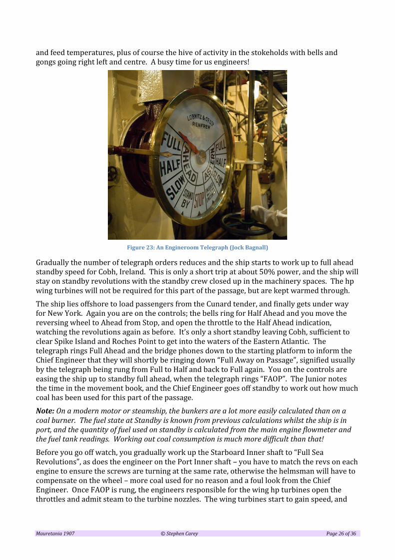
Figure 23: An Engineroom Telegraph (Jock Bagnall)
Gradually the number of telegraph orders reduces and the ship starts to work up to full ahead standby speed for Cobh, Ireland. This is only a short trip at about 50% power, and the ship will stay on standby revolutions with the standby crew closed up in the machinery spaces. The hp wing turbines will not be required for this part of the passage, but are kept warmed through.
The ship lies offshore to load passengers from the Cunard tender, and finally gets under way for New York. Again you are on the controls; the bells ring for Half Ahead and you move the reversing wheel to Ahead from Stop, and open the throttle to the Half Ahead indication, watching the revolutions again as before. It’s only a short standby leaving Cobh, sufficient to clear Spike Island and Roches Point to get into the waters of the Eastern Atlantic. The telegraph rings Full Ahead and the bridge phones down to the starting platform to inform the Chief Engineer that they will shortly be ringing down “Full Away on Passage”, signified usually by the telegraph being rung from Full to Half and back to Full again. You on the controls are easing the ship up to standby full ahead, when the telegraph rings “FAOP”. The Junior notes the time in the movement book, and the Chief Engineer goes off standby to work out how much coal has been used for this part of the passage.
Note: On a modern motor or steamship, the bunkers are a lot more easily calculated than on a coal burner. The fuel state at Standby is known from previous calculations whilst the ship is in port, and the quantity of fuel used on standby is calculated from the main engine flowmeter and the fuel tank readings. Working out coal consumption is much more difficult than that!
Before you go off watch, you gradually work up the Starboard Inner shaft to “Full Sea Revolutions”, as does the engineer on the Port Inner shaft – you have to match the revs on each engine to ensure the screws are turning at the same rate, otherwise the helmsman will have to compensate on the wheel – more coal used for no reason and a foul look from the Chief Engineer. Once FAOP is rung, the engineers responsible for the wing hp turbines open the throttles and admit steam to the turbine nozzles. The wing turbines start to gain speed, and

Mauretania 1907 © Stephen Carey Page 27 of 36
once well warmed through and drained, the ship’s speed increases dramatically. As this happens, the stokehold indicators are showing the firing sequence, taking into account the drawing and relaying of furnaces at the end of each watch, in order to keep the grates clean in rotation of clinker and ash.
As the hp turbines start to work up to speed, their exhaust expands into the inlet of our inner turbines, so we now start to close the lp turbine throttles as the exhaust from the hp sets takes over. We know what the steam chest pressure should be for full sea revolutions, and adjust our steam supply right down to finally closing the throttles completely. The propulsion plant is now working in a compound arrangement on each side of the ship, with the hp sets driving the outer shafts, and their exhaust into the lp sets driving the inner shafts. The exhaust steam from the lp sets is directed into the condensers, which are now handling a large amount of exhaust steam and condensate. The water pumps and air pumps are maintaining the condenser well level, the seawater pumps are adjusted to maximise the vacuum (along with the gland steam system) and the feed heaters are trimmed to give the highest possible water temperature into the feedwater pumps. We now have all the feed pumps going that are necessary to keep the water levels in the boilers. The stokeholds are an inferno; coal dust is swirling about, firemen and trimmers stripped to the waist are shovelling fuel from the bunkers to the stokehold floors to the furnaces at the increased firing rate, and ash is being shovelled into the ash chutes for disposal.
We are now heading across the North Atlantic for New York at a speed of some 23 knots – maintaining the Blue Riband for over 20 years.
Figure 24 View between the port and starboard lp turbines and starting platform
7 Coal-firing v oil-firing
Coal-firing was a dirty, messy, labour-intensive way to feed a furnace. As well as bunkering coal and firing the boilers, disposal of the ash was an additional burden on the stokehold staff. “Coaling ship” was a “whole ship” task where everyone turned-to in a mass effort to fill the coal

Mauretania 1907 © Stephen Carey Page 28 of 36
bunkers via coaling ports in the side of the ship. Very often the Captain himself was seen helping out on smaller ships.
Oil-burning on the other hand is far less dirty and labour-intensive, with the bunkering taking place via a hose from a bunker barge in to the same bunkers as the coal was previously (though made watertight of course).
A coal-fired ship of this size needed some 250 stokehold staff to fire and tend the boilers, whereas Mauretania when converted to oil firing only needed some 60-odd stokers.
Figure 25 Disposing of ash from a furnace
Figure 26: Filthy conditions in a coal-fired stokehold

Mauretania 1907 © Stephen Carey Page 29 of 36
Figure 27 Mauretania stokehold after conversion
From the pictures above, compared to the filthy conditions in a coal-fired ship, can be seen the huge improvement in working conditions once the stokehold had been converted to oil firing.
In addition, firing on oil was far more efficient, and the power output of Mauretania improved substantially after conversion*, as did the overall Specific Fuel Consumption. As there was no requirement to discharge ash overboard, the ship was much cleaner and – even though the environment was not much considered in those days – oil firing opened up the world shipping fleets to better environmental conditions. The volume of smoke seen issuing from the funnels of these large passenger ships also reduced dramatically; an oil-fired boiler is designed to run cleanly, with no smoke other than a haze at the funnel tops, whereas it was difficult to avoid smoke – especially whilst manoeuvring – from over 20 boilers fired on coal. The coal fires are slow to react to changes in steam demand and draught requirements, whereas oil-firing can react almost immediately.
One procedure that didn’t really improve was the length of time taken to raise steam in fire-tube boilers, and it was some years before the next major trans-Atlantic steamship was built using water-tube boilers. This was the Empress of Britain, which will be discussed in a further document on starting these large liners from cold.
* However, not immediately as the ship recorded some of its slowest passages after conversion, one at a mere 19 knots. After her war service where maintenance was at a minimum, the Company decided to give her turbines a much needed overhaul, after which she returned to record-breaking performance with an oil consumption of some 750 tons per 24 hours, compared to 1,000 tons of coal. And of course a dramatic reduction in boiler room staff.

Mauretania 1907 © Stephen Carey Page 30 of 36
PLATES FROM THE PUBLICATION “OCEAN LINERS OF THE PAST, THE LUSITANIA AND MAURETANIA
(With notes to explain the various items of equipment fitted)

Mauretania 1907 © Stephen Carey Page 31 of 36
Figure 28 Plan of boiler rooms up to the ER bulkhead

Mauretania 1907 © Stephen Carey Page 32 of 36
8 Profile & Plan of Boiler Rooms
On the view in Figure 28 can be seen the extent of boiler rooms 2,3 and 4, with a hint of Boiler Room 1 at the fore ends. The boilers are installed 6 to a room.
8.1 Uptakes and ash ejectors
The uptakes can clearly be seen, illustrating that all four funnels on this vessel served the boilers (unlike the Titanic, whose aft funnel was a ventilation shaft.
Zooming in on the drawing shows the ash ejectors in boiler rooms 2&4, and the ash ejector pump is shown in boiler room 2.
8.2 Auxiliary feed pumps
There is an auxiliary feed pump either side of the watertight bulkhead between numbers 2 & 3 boiler rooms. No1 and No4 boiler rooms also have an auxiliary feed pump and ash ejector.
8.3 Main steam lines, FD Fans and escape ladders
On the profile view, note the main steam lines running the length of the ship above the boilers, the forced draft fans mounted on the Orlop Deck. Also the vertical ladders the same as the Titanic where they stokers can get out of the stokehold if the watertight doors are closed.

Mauretania 1907 © Stephen Carey Page 33 of 36
Figure 29 Plan of machinery spaces

Mauretania 1907 © Stephen Carey Page 34 of 36
Figure 30 Elevation of machinery spaces

Mauretania 1907 © Stephen Carey Page 35 of 36
9 Plan and elevation of machinery rooms
The views in Figure 28 and Figure 30 show the forward engineroom bulkhead on which are the bulkhead stops for the two main steam lines exiting from No4 boiler room. The bulkhead stops are actuated by Brown’s steam engines as they are too large to manually operate. The engine overspeed governor can act on these valves and shut off the steam in the event of overspeed.
The turbines and equipment are mirrored for each pair of shafts. For the notes below we will consider the port side pair of shafts to avoid repetition.
9.1 Steam lines
The steam, after passing though a strainer to remove particles, is directed either to the hp turbine via the pipe passing through the watertight longitudinal bulkhead, or aft to the lp turbines via the large double manoeuvring valve shown at Fr 94. The starting platform from where the engines are driven ahead and astern is located at the forward end of the astern lp turbines and can be seen around Fr 104. The starting wheels comprise a large outer wheel for the bulkhead stops, and a smaller inner wheel for the manoeuvring valve. The levers for controlling the turbine drains and sluice valves are close by.
9.2 Turbine isolation
Taking the port hp turbine as an example, there are two exhaust pipes exiting from the turbine casing, both of which have large sluice valves installed. The after larger one (75”) directs hp exhaust steam into the inlet of the lp turbine, which is the normal mode at sea. The other smaller (60”) sluice valve directs the exhaust straight to the condenser (in the event that the lp set is out of service) and is therefore normally closed. Whilst manoeuvring, both sluice valves are kept shut to avoid steam back flowing from the lp turbines into the idle hp turbines.
The exhaust from the lp turbines to the condensers is the large length of piping shown at the aft end of the ahead lp turbine, which passes through two watertight bulkheads and into the main condenser.
9.3 Main manoeuvring valves
Around Fr 93 and in line with the steam lines to the lp turbines can be seen the double outline of the manoeuvring valve that directs steam either into the ahead lp turbine (the larger pipe) or the astern turbine (the smaller pipe).
9.4 Feedwater pumps
Along the forward bulkhead in both hp and lp engine rooms are arranged the main feedwater pumps. These pumps draw from the direct/contact feed heater mounted on the flat above the turbines
9.5 Auxiliary equipment
A set of evaporator machinery for producing fresh water is installed in each hp turbine room, while aft of these are the fresh and condensed water pumps in the
Mauretania 1907 © Stephen Carey Page 36 of 36
port room, and refrigeration machinery in the starboard hp turbine room. Space is therefore limited in both these rooms.
In the lp room are fitted the hotwell, bilge, oil, water service, fire and sanitary pumps.
In the Auxiliary condenser rooms can be seen the condensers themselves, the condenser seawater pumps and air pumps, the main and auxiliary feedwater filters and the surface feed heaters. The Stone-Lloyd pumps shown outboard in the port room are for operating the watertight doors.
9.6 Main condenser room
In the main condenser room are installed the main condensers. Note that there is no centreline bulkhead in this room. Mounted under the condensers are the hotwells for collecting the condensed steam, and the hotwell pumps that pump the condensate into the feed system.
9.7 Auxiliary Machinery Rooms
Aft of the condenser room, the next watertight compartment contains the two large main condenser seawater-circulating pumps, the main wet-air pumps and the dry-air pumps for creating the vacuum on the condensers. The dry-air pumps are mounted one set above the other.
Above the auxiliary machinery room is situated the turbo-generator room and its attendant main switchboard.
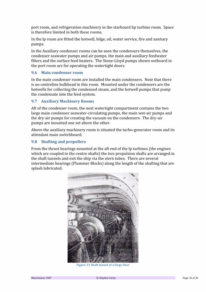
9.8 Shafting and propellers
From the thrust bearings mounted at the aft end of the lp turbines (the engines which are coupled to the centre shafts) the two propulsion shafts are arranged in the shaft tunnels and exit the ship via the stern tubes. There are several intermediate bearings (Plummer Blocks) along the length of the shafting that are splash lubricated.
Figure 31 Shaft tunnel of a large liner


![[SW] Dune Encyclopedia Russian](https://img.pdfslide.tips/doc/110x75/5449cb29b1af9f046d8b4638/sw-dune-encyclopedia-russian.jpg)