Embed Size (px)
Citation preview
1
ROUGH-RIDER 700 UTVMaintenance Manual
2
Catalog
General Information……………………………...5
1 Description…………………………………………………..5
1.1 Identification code…...6
1.1.1. Frame No. …………………………………………………6
1.1.2. Engine No.…………………………………………………7
1.2 Special tools, instruments and meters…………………7
1.3 Periodic maintenance chart……………………………….10
Engine………………………………………………………….11
2. Inspection and adjustment of engine…………….11
2.1 Inspection of cylinder head, intake
And exhaust valve………………………………………….11
2.2 Inspection of spark Plug………………………………….14
2.3 Inspection of cylinder, piston and piston ring…….15
2.4 Inspection of crankshaft………………………………….18
2.5 Inspection of clutch……………………………………….19
2.6 Inspection of carburetor………………………………….19
2.7 Inspection of air filter………………………………….20
2.8 Inspection of oil filter………………………………….21
2.9 Inspection of lubrication system……………………….21
2.10 Lubrication of engine…………………………………….22
2.11 Inspection of cylinder head…………………………….22
3
3. Disassembly of engine……………………………………27
3.1 Cylinder head and block………………………………….27
3.2 Piston and connecting rod……………………………….32
3.3 starting mechanism………………………………………..33
3.4 Sensor………………………………………………….…….33
3.5 Left crankcase cover……………………………….…….33
3.6 Magneto…………………………………………………..….34
3.7 Oil pump………………………………………….……..….34
3.8 Clutch…………………………………………………...….36
3.9 Carburetor……………………………………………...….36
3.9.1 Structure of carburetor…...36
3.9.2 Inspection and adjustment of carburetor…....….37
4. Chassis
4.1 Direction system…...42
4.2 Brake system…………………………………………...….57
4.3 Wheels and tires……………………………………...….77
4.4 Transmission system…………………………….…...….81
4.5.Reverse mechanism parts………………………………89
4.6 Suspension……....91
4.7 Cooling System of Engine………………..97
4
4.8 Lubrication points……….102
5. Electrical system…....105
5.1 Ignition system…....108
5.2 Magneto and charging system…....109
5.3 Battery…....110
5.4 Lighting system…....111
5.5 Meter and signal system…………………………..……112
5.6 Electrical starting system…………….……..…….113
6. Appendix…...115
6.1 Specification…....115
6.2 Requirements for torque of fastener……………….121
6.3 Electrical circuits……………………………....….122
5
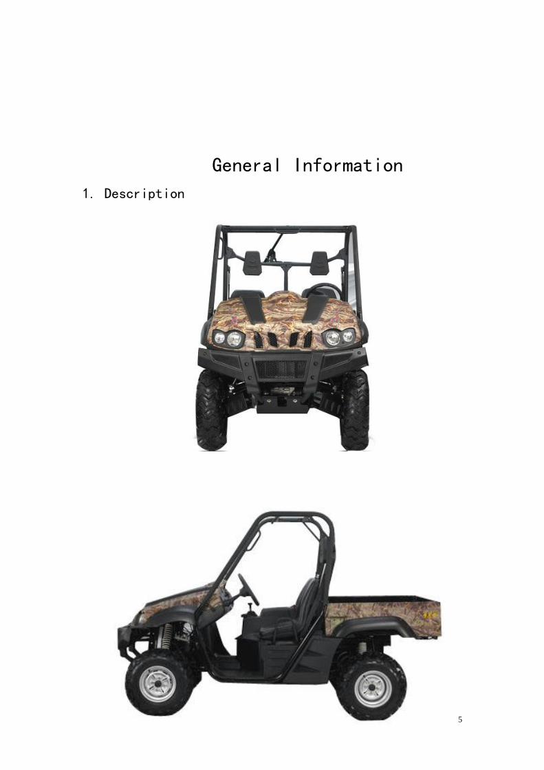
General Information
1. Description
6
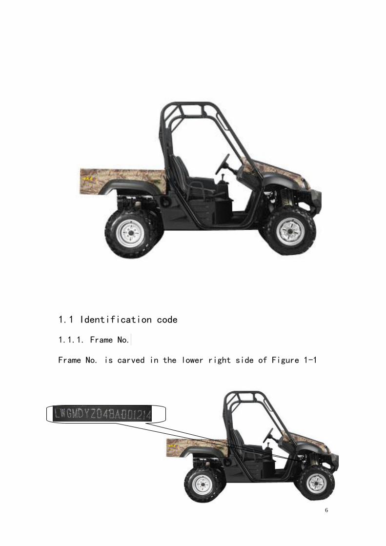
1.1 Identification code
1.1.1. Frame No.
Frame No. is carved in the lower right side of Figure 1-1
7
Figure 1-1
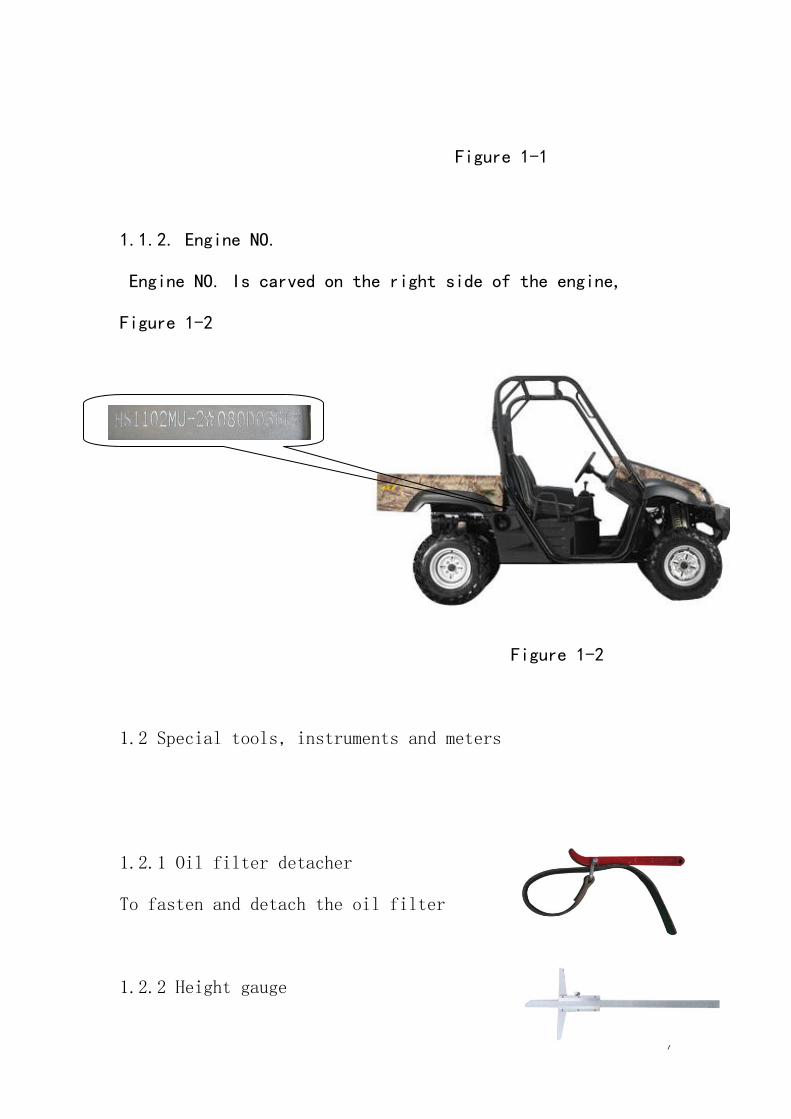
1.1.2. Engine NO.
Engine NO. Is carved on the right side of the engine,
Figure 1-2
Figure 1-2
1.2 Special tools, instruments and meters
1.2.1 Oil filter detacher
To fasten and detach the oil filter
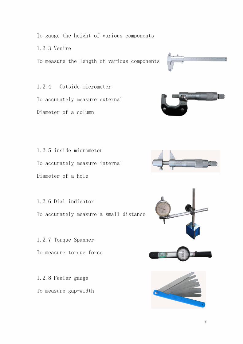
1.2.2 Height gauge
8
To gauge the height of various components
1.2.3 Venire
To measure the length of various components
1.2.4 Outside micrometer
To accurately measure external
Diameter of a column
1.2.5 inside micrometer
To accurately measure internal
Diameter of a hole
1.2.6 Dial indicator
To accurately measure a small distance
1.2.7 Torque Spanner
To measure torque force
1.2.8 Feeler gauge
To measure gap-width
9
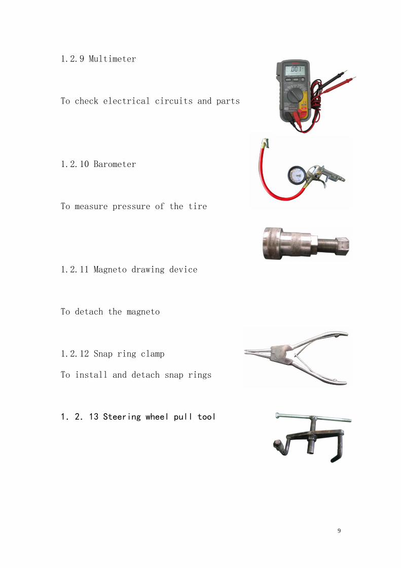
1.2.9 Multimeter
To check electrical circuits and parts
1.2.10 Barometer
To measure pressure of the tire
1.2.11 Magneto drawing device
To detach the magneto
1.2.12 Snap ring clamp
To install and detach snap rings
1.2.13 Steering wheel pull tool
10
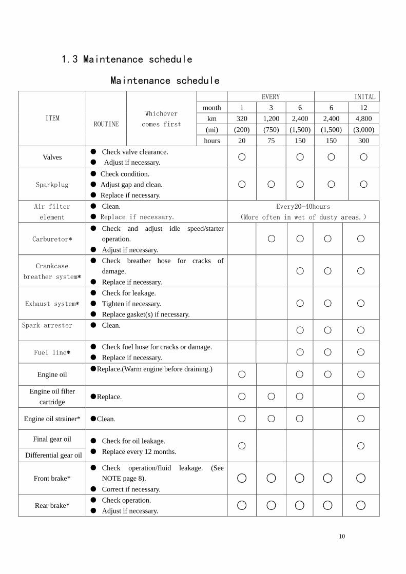
1.3 Maintenance schedule
Maintenance schedule
ITEM
ROUTINE
Whichever
comes first
EVERY INITAL
month 1 3 6 6 12
km 320 1,200 2,400 2,400 4,800
(mi) (200) (750) (1,500) (1,500) (3,000)
hours 20 75 150 150 300
Valves ● Check valve clearance.
● Adjust if necessary. ○ ○ ○ ○
Sparkplug
● Check condition.
● Adjust gap and clean.
● Replace if necessary. ○ ○ ○ ○ ○
Air filter
element
● Clean.
● Replace if necessary.
Every20-40hours
(More often in wet of dusty areas.)
Carburetor*
● Check and adjust idle speed/starter
operation.
● Adjust if necessary.
○ ○ ○ ○
Crankcase
breather system*
● Check breather hose for cracks of
damage.
● Replace if necessary.
○ ○ ○
Exhaust system*
● Check for leakage.
● Tighten if necessary.
● Replace gasket(s) if necessary.
○ ○ ○
Spark arrester ● Clean. ○ ○ ○
Fuel line* ● Check fuel hose for cracks or damage.
● Replace if necessary. ○ ○ ○
Engine oil ●Replace.(Warm engine before draining.)
○ ○ ○ ○
Engine oil filter
cartridge ●Replace. ○ ○ ○ ○
Engine oil strainer* ●Clean. ○ ○ ○ ○
Final gear oil ● Check for oil leakage.
● Replace every 12 months. ○ ○
Differential gear oil
Front brake*
● Check operation/fluid leakage. (See
NOTE page 8).
● Correct if necessary.
○ ○ ○ ○ ○
Rear brake* ● Check operation.
● Adjust if necessary. ○ ○ ○ ○ ○
11
Select lever safety
system cable
● Check operation.
● Adjust if necessary. ○ ○ ○
V-belt* ● Check operation.
● Check for cracks or damage. ○ ○ ○ ○
Wheel ● Check balance/damage/
● Repair if necessary. ○ ○ ○ ○
Wheel bearing*
● Check bearing assemblies for loose/
Damage.
● Replace if necessary.
○ ○ ○ ○
Front and rear
suspension*
● Check operation.
● Correct if necessary. ○ ○
Steering system* ● Check operation./Replace if damaged
● Check toe-in. /Adjust if necessary. ○ ○ ○ ○ ○
Drive shaft universal
joint*
● Lubricate with lithium–soap–based
grease. ○ ○ ○
Axle boots* ● Check operation.
● Replace if damaged. ○ ○ ○ ○ ○
Fittings and
fasteners*
● Check all chassis fittings and fasteners.
● Correct if necessary. ○ ○ ○ ○ ○
Lights and
switches*
● Check operation.
● Adjust headlight beams. ○ ○ ○ ○ ○
Engine
2. Inspection and adjustment of engine
2.1 Inspection of cylinder head, intake
And exhaust valve
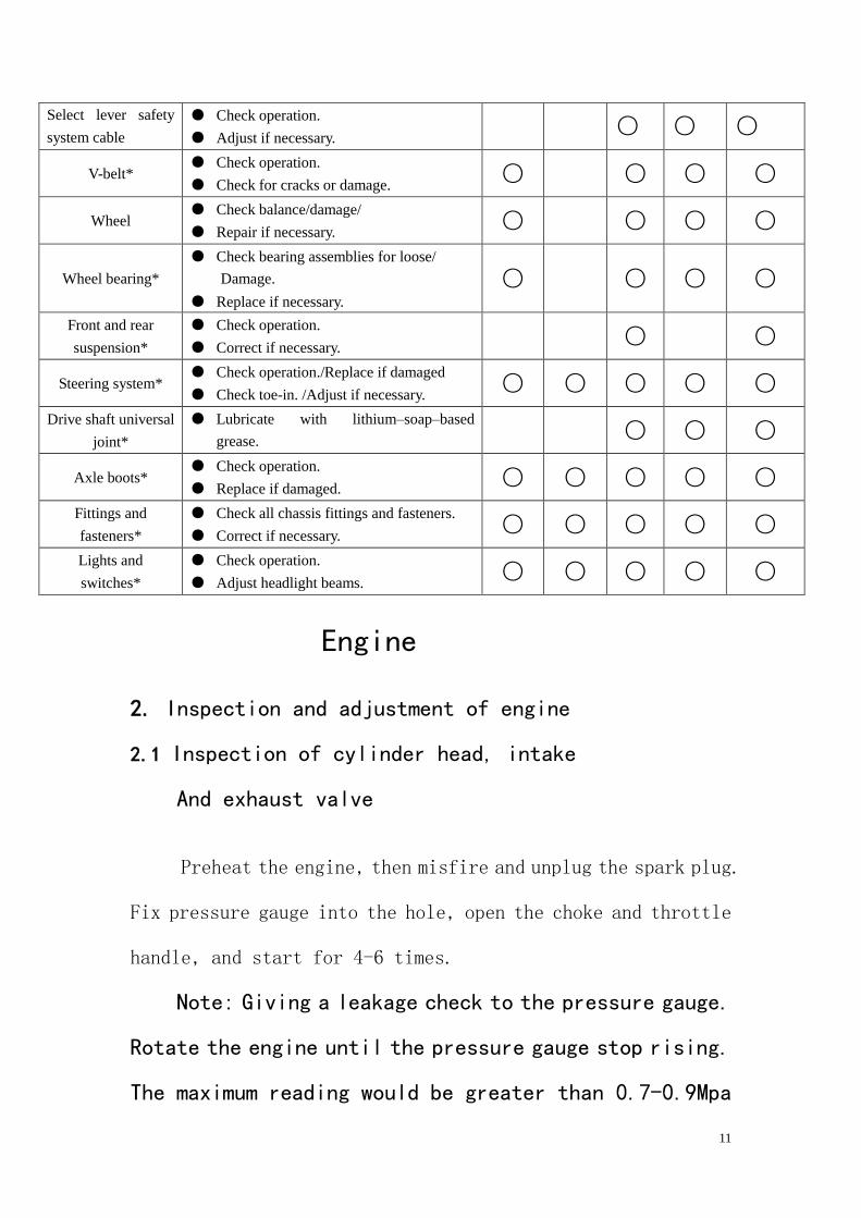
Preheat the engine, then misfire and unplug the spark plug.
Fix pressure gauge into the hole, open the choke and throttle
handle, and start for 4-6 times.
Note: Giving a leakage check to the pressure gauge.
Rotate the engine until the pressure gauge stop rising.
The maximum reading would be greater than 0.7-0.9Mpa
12
after starting for 4-6 times.
See figure 2-1.
Figure 2-1
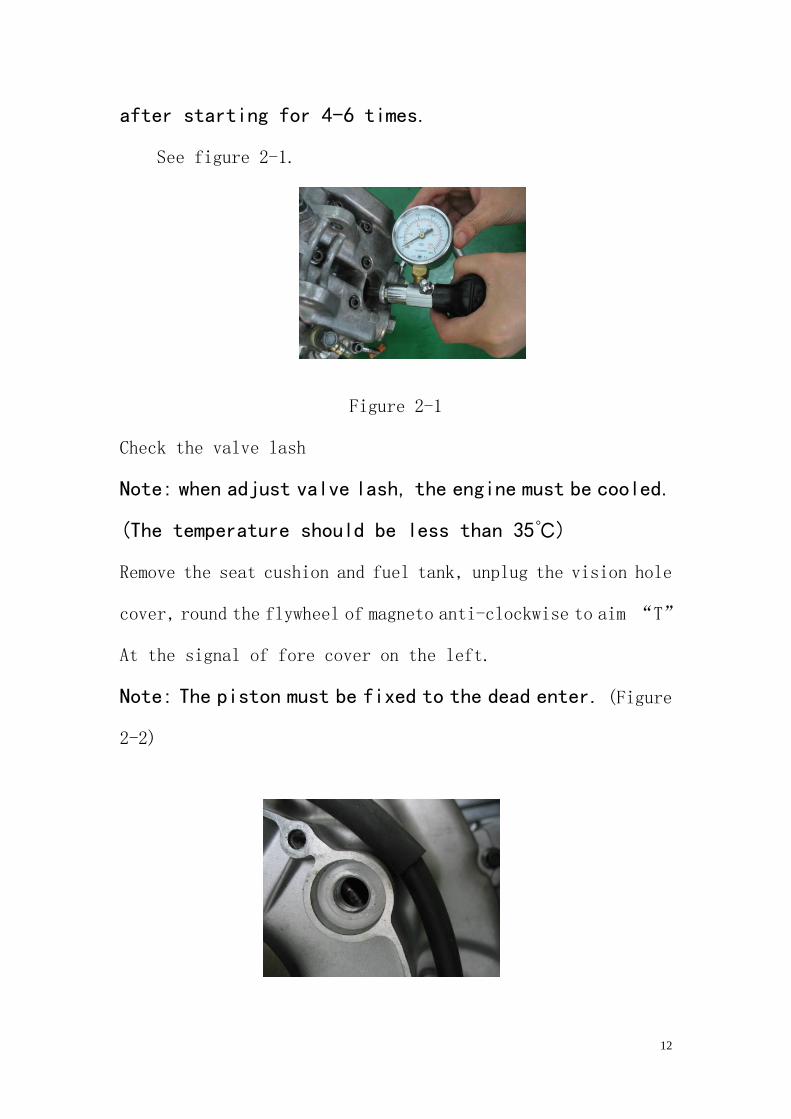
Check the valve lash
Note: when adjust valve lash, the engine must be cooled.
(The temperature should be less than 35℃)
Remove the seat cushion and fuel tank, unplug the vision hole
cover, round the flywheel of magneto anti-clockwise to aim “T”
At the signal of fore cover on the left.
Note: The piston must be fixed to the dead enter. (Figure
2-2)
13
Figure 2-2
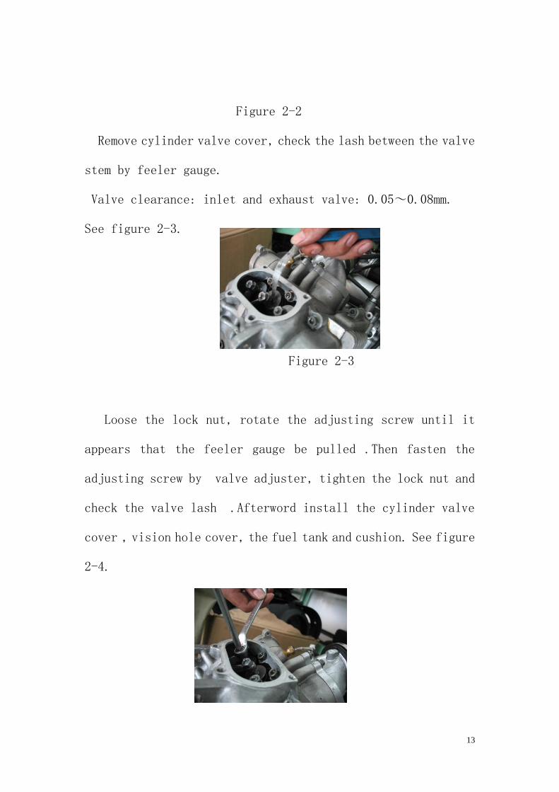
Remove cylinder valve cover, check the lash between the valve
stem by feeler gauge.
Valve clearance: inlet and exhaust valve: 0.05~0.08mm.
See figure 2-3.
Figure 2-3
Loose the lock nut, rotate the adjusting screw until it
appears that the feeler gauge be pulled .Then fasten the
adjusting screw by valve adjuster, tighten the lock nut and
check the valve lash .Afterword install the cylinder valve
cover , vision hole cover, the fuel tank and cushion. See figure
2-4.
14
Figure 2-4
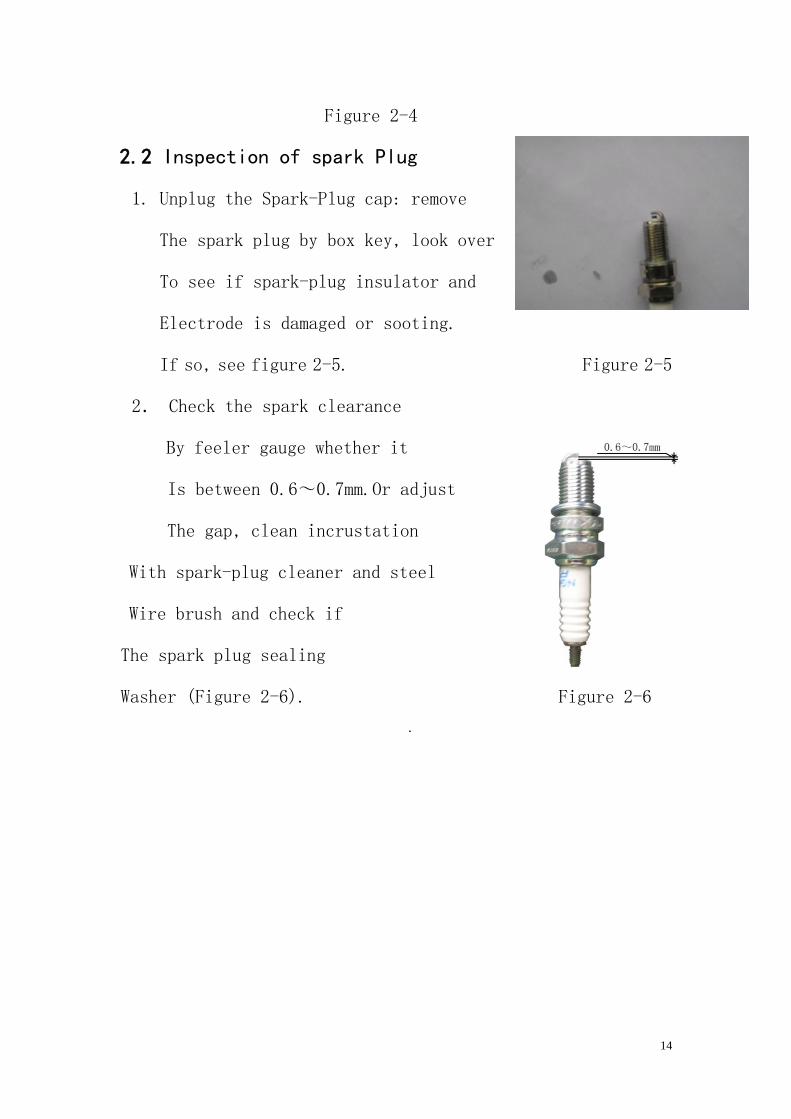
2.2 Inspection of spark Plug
1. Unplug the Spark-Plug cap: remove
The spark plug by box key, look over
To see if spark-plug insulator and
Electrode is damaged or sooting.
If so, see figure 2-5. Figure 2-5
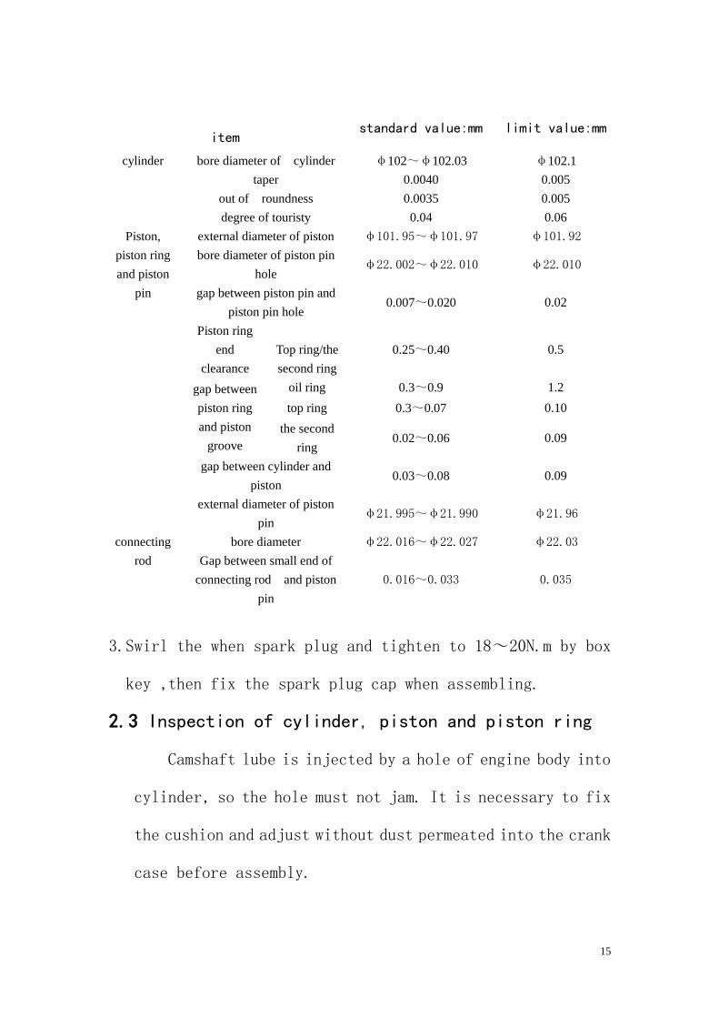
2. Check the spark clearance
By feeler gauge whether it
Is between 0.6~0.7mm.Or adjust
The gap, clean incrustation
With spark-plug cleaner and steel
Wire brush and check if
The spark plug sealing
Washer (Figure 2-6). Figure 2-6
.
15
3.Swirl the when spark plug and tighten to 18~20N.m by box
key ,then fix the spark plug cap when assembling.
2.3 Inspection of cylinder, piston and piston ring
Camshaft lube is injected by a hole of engine body into
cylinder, so the hole must not jam. It is necessary to fix
the cushion and adjust without dust permeated into the crank
case before assembly.
item standard value:mm limit value:mm
cylinder bore diameter of cylinder φ102~φ102.03 φ102.1
taper 0.0040 0.005
out of roundness 0.0035 0.005
degree of touristy 0.04 0.06
Piston,
piston ring
and piston
pin
external diameter of piston φ101.95~φ101.97 φ101.92
bore diameter of piston pin
hole φ22.002~φ22.010 φ22.010
gap between piston pin and
piston pin hole 0.007~0.020 0.02
Piston ring
end
clearance
Top ring/the
second ring
0.25~0.40 0.5
gap between
piston ring
and piston
groove
oil ring 0.3~0.9 1.2
top ring 0.3~0.07 0.10
the second
ring 0.02~0.06 0.09
gap between cylinder and
piston 0.03~0.08 0.09
external diameter of piston
pin φ21.995~φ21.990 φ21.96
connecting
rod
bore diameter φ22.016~φ22.027 φ22.03
Gap between small end of
connecting rod and piston
pin
0.016~0.033 0.035
16
Diagnosing and eliminating of malfunction:
● Emission of black smoke for abrasion of cylinder
or piston,
1. Cylinder, piston of piston ring is worn out.
2. The piston ring is not properly assembled.
3. The piston or cylinder wall is scraped.
● overheated
1、Excessive incrustation of piston.
2、Blast and abnormal noise.
3、Abrasion of cylinder or piston.
Inspection of cylinder.
1. Check whether the cylinder is damaged.
2. Measure the bore diameter of cylinder at three spots.
3. At the top, the middle and the bottom of the piston
stroke .And measure the bore diameter at directions of
right-angle intersection.
Repairing limit value:
Out of roundness: 0.005 mm
Taper :0.005mm
Inspection of piston and piston ring
Measure the gap between piston ring and piston groove.
1. Unplug the piston ring;
17
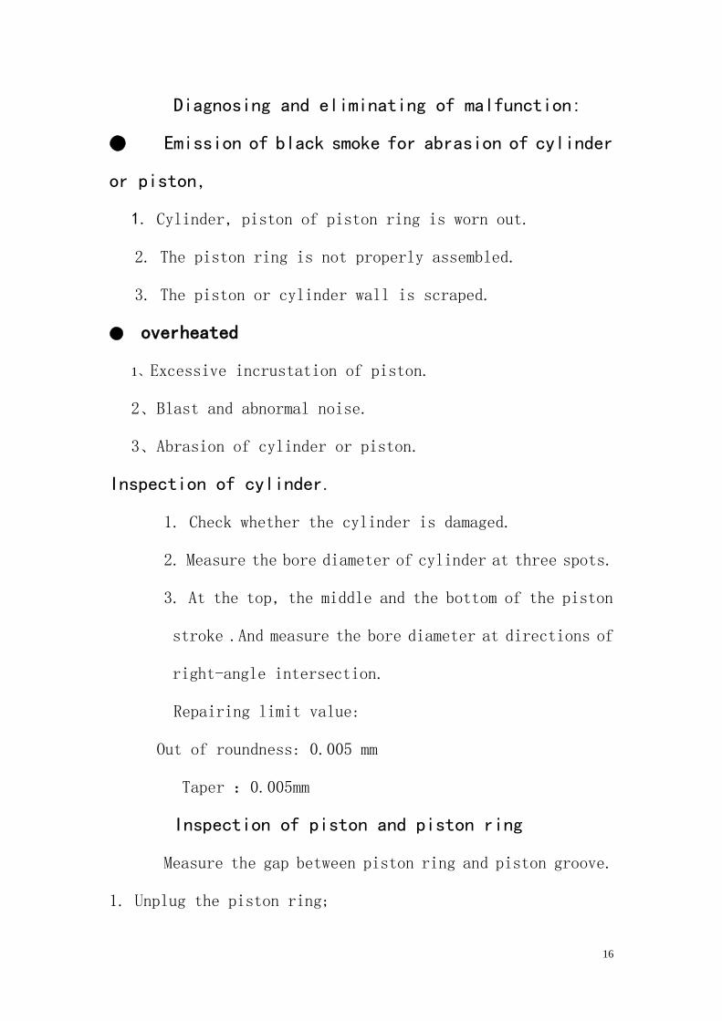
Note: It is forbidden to damaging the piston ring when
assembling. Check whether the piston and the piston groove
is cracked and abraded. See figure 2-7
Figure 2-7
2. Insert piston ring into
Cylinder, and measure the
End gap. Repairing limit
Value: the first ring/the
Second ring: 0.5mm
See figure 2-8. Figure 2-8
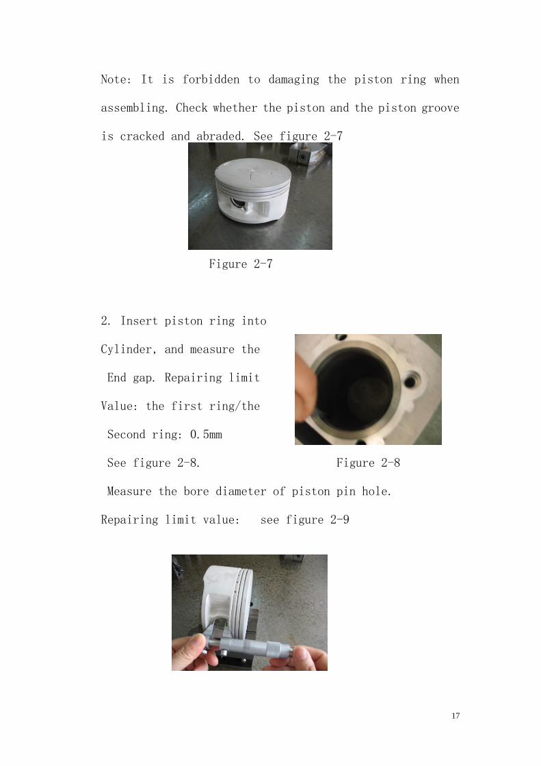
Measure the bore diameter of piston pin hole.
Repairing limit value: see figure 2-9
18
Figure 2-9
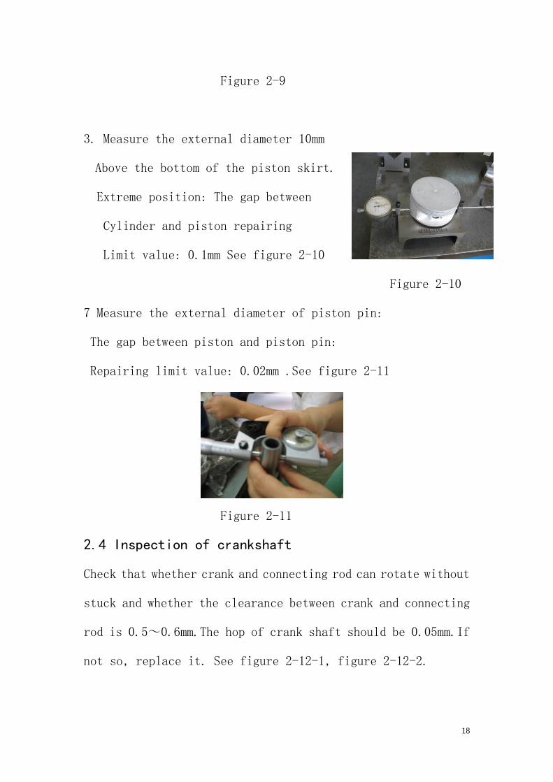
3. Measure the external diameter 10mm
Above the bottom of the piston skirt.
Extreme position: The gap between
Cylinder and piston repairing
Limit value: 0.1mm See figure 2-10
Figure 2-10
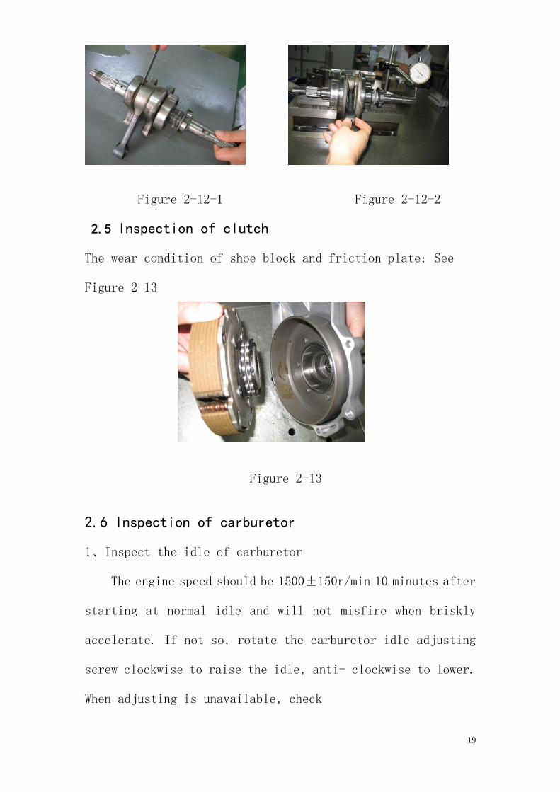
7 Measure the external diameter of piston pin:
The gap between piston and piston pin:
Repairing limit value: 0.02mm .See figure 2-11
Figure 2-11
2.4 Inspection of crankshaft
Check that whether crank and connecting rod can rotate without
stuck and whether the clearance between crank and connecting
rod is 0.5~0.6mm.The hop of crank shaft should be 0.05mm.If
not so, replace it. See figure 2-12-1, figure 2-12-2.
19
Figure 2-12-1 Figure 2-12-2
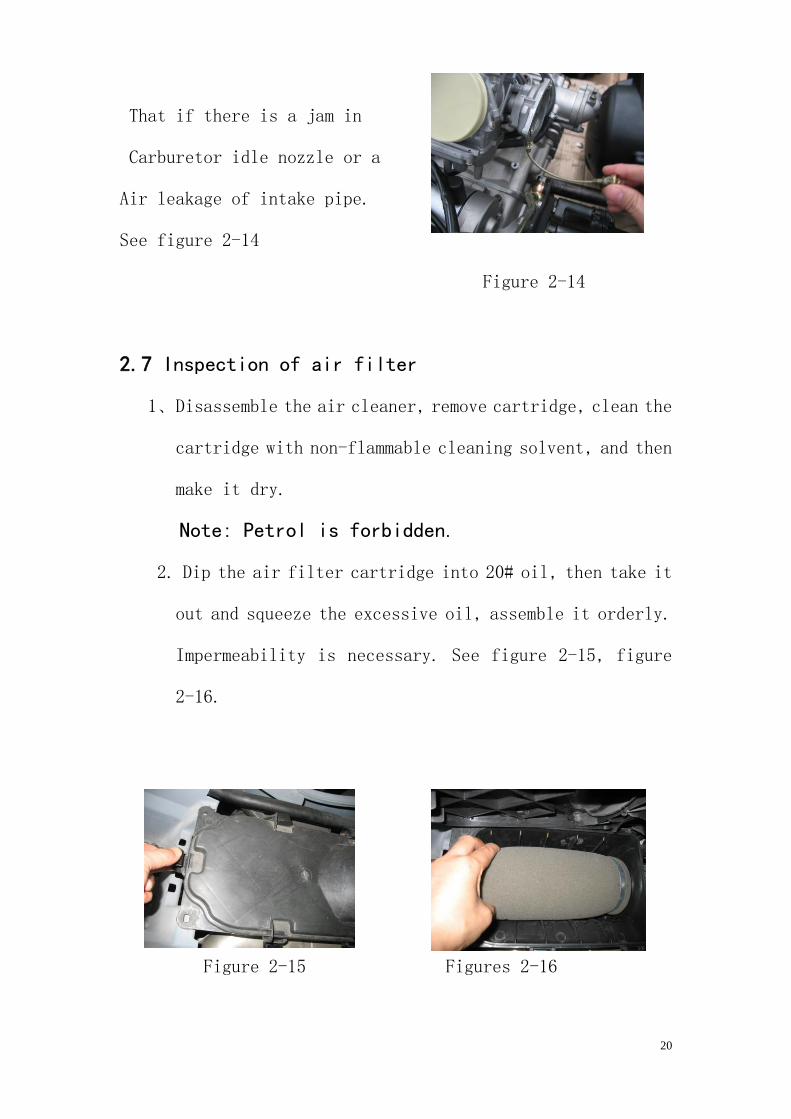
2.5 Inspection of clutch
The wear condition of shoe block and friction plate: See
Figure 2-13
Figure 2-13
2.6 Inspection of carburetor
1、Inspect the idle of carburetor
The engine speed should be 1500±150r/min 10 minutes after
starting at normal idle and will not misfire when briskly
accelerate. If not so, rotate the carburetor idle adjusting
screw clockwise to raise the idle, anti- clockwise to lower.
When adjusting is unavailable, check
20
That if there is a jam in
Carburetor idle nozzle or a
Air leakage of intake pipe.
See figure 2-14
Figure 2-14
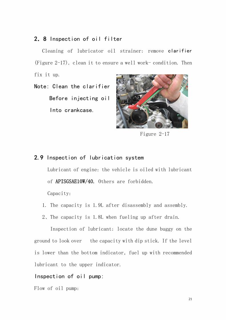
2.7 Inspection of air filter
1、Disassemble the air cleaner, remove cartridge, clean the
cartridge with non-flammable cleaning solvent, and then
make it dry.
Note: Petrol is forbidden.
2. Dip the air filter cartridge into 20# oil, then take it
out and squeeze the excessive oil, assemble it orderly.
Impermeability is necessary. See figure 2-15, figure
2-16.
Figure 2-15 Figures 2-16
21
2.8 Inspection of oil filter
Cleaning of lubricator oil strainer: remove clarifier
(Figure 2-17), clean it to ensure a well work- condition. Then
fix it up.
Note: Clean the clarifier
Before injecting oil
Into crankcase.
Figure 2-17
2.9 Inspection of lubrication system
Lubricant of engine: the vehicle is oiled with lubricant
of APISGSAE10W/40. Others are forbidden.
Capacity:
1. The capacity is 1.9L after disassembly and assembly.
2、The capacity is 1.8L when fueling up after drain.
Inspection of lubricant: locate the dune buggy on the
ground to look over the capacity with dip stick. If the level
is lower than the bottom indicator, fuel up with recommended
lubricant to the upper indicator.
Inspection of oil pump:
Flow of oil pump:
22
r/min 1000 2000 3000
L/min 3.78 7.43 10.89
Measure clearance of the top of internal external rotor
Limit value: 0.20mm
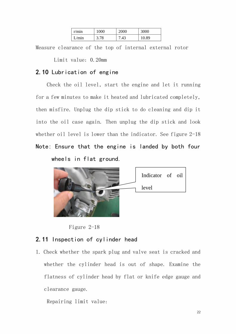
2.10 Lubrication of engine
Check the oil level, start the engine and let it running
for a few minutes to make it heated and lubricated completely,
then misfire. Unplug the dip stick to do cleaning and dip it
into the oil case again. Then unplug the dip stick and look
whether oil level is lower than the indicator. See figure 2-18
Note: Ensure that the engine is landed by both four
wheels in flat ground.
Figure 2-18
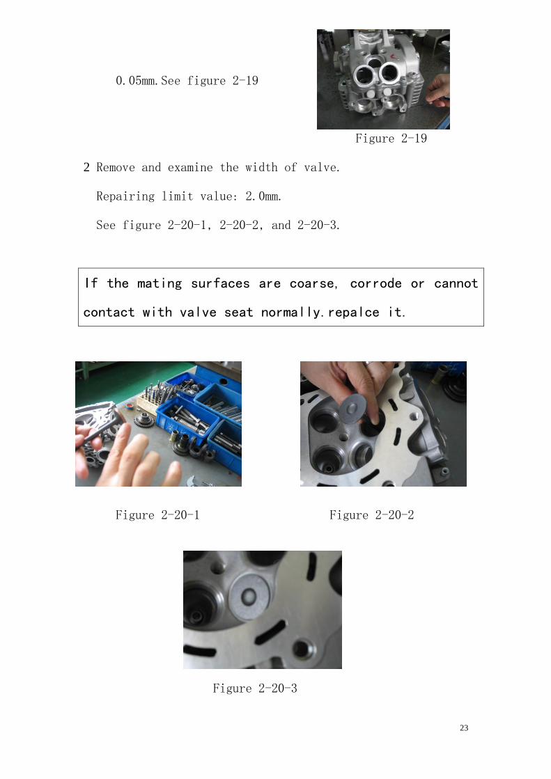
2.11 Inspection of cylinder head
1. Check whether the spark plug and valve seat is cracked and
whether the cylinder head is out of shape. Examine the
flatness of cylinder head by flat or knife edge gauge and
clearance gauge.
Repairing limit value:
Indicator of oil
level
23
0.05mm.See figure 2-19
Figure 2-19
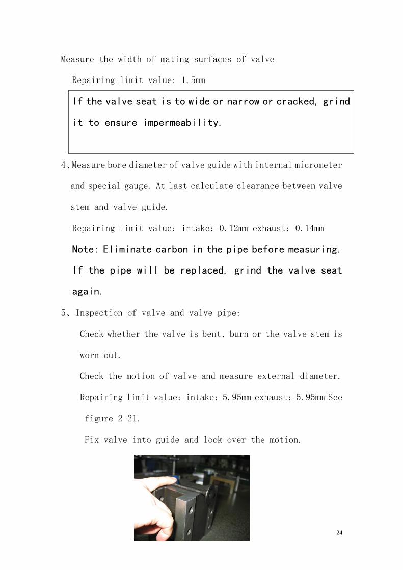
2 Remove and examine the width of valve.
Repairing limit value: 2.0mm.
See figure 2-20-1, 2-20-2, and 2-20-3.
Figure 2-20-1 Figure 2-20-2
Figure 2-20-3
If the mating surfaces are coarse, corrode or cannot
contact with valve seat normally.repalce it.
24
Measure the width of mating surfaces of valve
Repairing limit value: 1.5mm
If the valve seat is to wide or narrow or cracked, grind
it to ensure impermeability.
4、Measure bore diameter of valve guide with internal micrometer
and special gauge. At last calculate clearance between valve
stem and valve guide.
Repairing limit value: intake: 0.12mm exhaust: 0.14mm
Note: Eliminate carbon in the pipe before measuring.
If the pipe will be replaced, grind the valve seat
again.
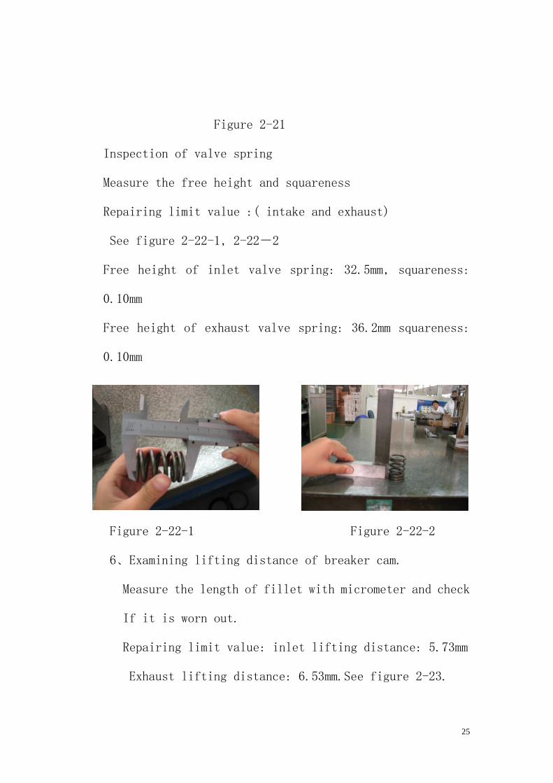
5、Inspection of valve and valve pipe:
Check whether the valve is bent, burn or the valve stem is
worn out.
Check the motion of valve and measure external diameter.
Repairing limit value: intake: 5.95mm exhaust: 5.95mm See
figure 2-21.
Fix valve into guide and look over the motion.
25
Figure 2-21
Inspection of valve spring
Measure the free height and squareness
Repairing limit value :( intake and exhaust)
See figure 2-22-1, 2-22-2
Free height of inlet valve spring: 32.5mm, squareness:
0.10mm
Free height of exhaust valve spring: 36.2mm squareness:
0.10mm
Figure 2-22-1 Figure 2-22-2
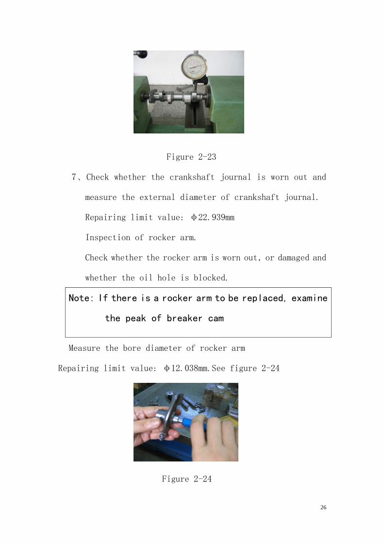
6、Examining lifting distance of breaker cam.
Measure the length of fillet with micrometer and check
If it is worn out.
Repairing limit value: inlet lifting distance: 5.73mm
Exhaust lifting distance: 6.53mm.See figure 2-23.
26
Figure 2-23
7、Check whether the crankshaft journal is worn out and
measure the external diameter of crankshaft journal.
Repairing limit value: φ22.939mm
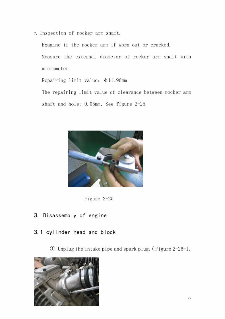
Inspection of rocker arm.
Check whether the rocker arm is worn out, or damaged and
whether the oil hole is blocked.
Note: If there is a rocker arm to be replaced, examine
the peak of breaker cam
Measure the bore diameter of rocker arm
Repairing limit value: φ12.038mm.See figure 2-24
Figure 2-24
27
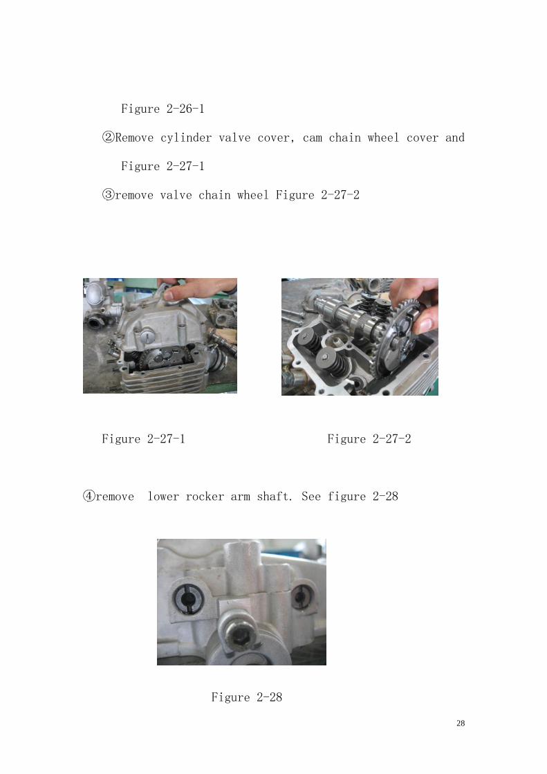
7. Inspection of rocker arm shaft.
Examine if the rocker arm if worn out or cracked.
Measure the external diameter of rocker arm shaft with
micrometer.
Repairing limit value: φ11.96mm
The repairing limit value of clearance between rocker arm
shaft and hole: 0.05mm, See figure 2-25
Figure 2-25
3. Disassembly of engine
3.1 cylinder head and block
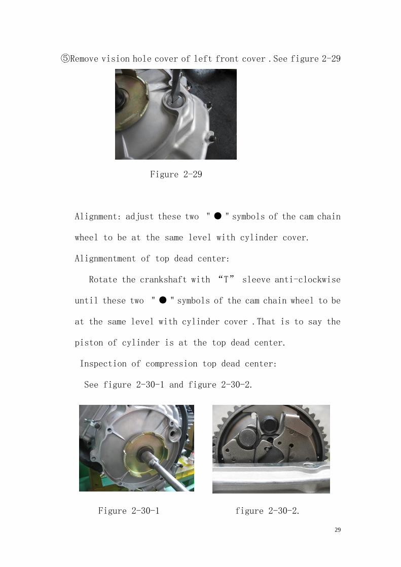
① Unplug the intake pipe and spark plug.( Figure 2-26-1,
28
Figure 2-26-1
②Remove cylinder valve cover, cam chain wheel cover and
Figure 2-27-1
③remove valve chain wheel Figure 2-27-2
Figure 2-27-1 Figure 2-27-2
④remove lower rocker arm shaft. See figure 2-28
Figure 2-28
29
⑤Remove vision hole cover of left front cover .See figure 2-29
Figure 2-29
Alignment: adjust these two "●"symbols of the cam chain
wheel to be at the same level with cylinder cover.
Alignmentment of top dead center:
Rotate the crankshaft with “T” sleeve anti-clockwise
until these two "●"symbols of the cam chain wheel to be
at the same level with cylinder cover .That is to say the
piston of cylinder is at the top dead center.
Inspection of compression top dead center:
See figure 2-30-1 and figure 2-30-2.
Figure 2-30-1 figure 2-30-2.

30
When inlet valve spring rise, rotate the crankshaft until
the “T” indicator on the magneto rotor to be at the same
level with the center of vision whole cover of left front
cover. That is to say the piston is at the compression top
dead center and there is valve clearance in these four rocker
arms of cylinder head. See figure 2-31
Figure 2-31
Remove chain tensioner adjuster. See figure 2-32.
Figure 2-32
Remove the cylinder head
Loosen the bolt by intersection manner before remove the bolt.
31
See figure 2-33.
Figure 2-33
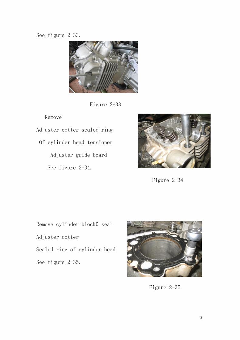
Remove
Adjuster cotter sealed ring
Of cylinder head tensioner
Adjuster guide board
See figure 2-34.
Figure 2-34
Remove cylinder block0-seal
Adjuster cotter
Sealed ring of cylinder head
See figure 2-35.
Figure 2-35
32
3.2 piston and connecting rod
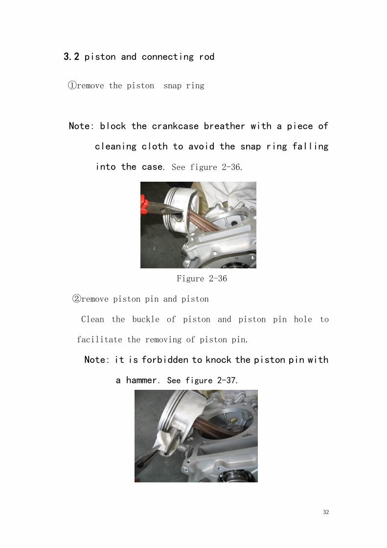
①remove the piston snap ring
Note: block the crankcase breather with a piece of
cleaning cloth to avoid the snap ring falling
into the case. See figure 2-36.
Figure 2-36
②remove piston pin and piston
Clean the buckle of piston and piston pin hole to
facilitate the removing of piston pin.
Note: it is forbidden to knock the piston pin with
a hammer. See figure 2-37.
33
Figure 2-37
3.3 starting mechanism
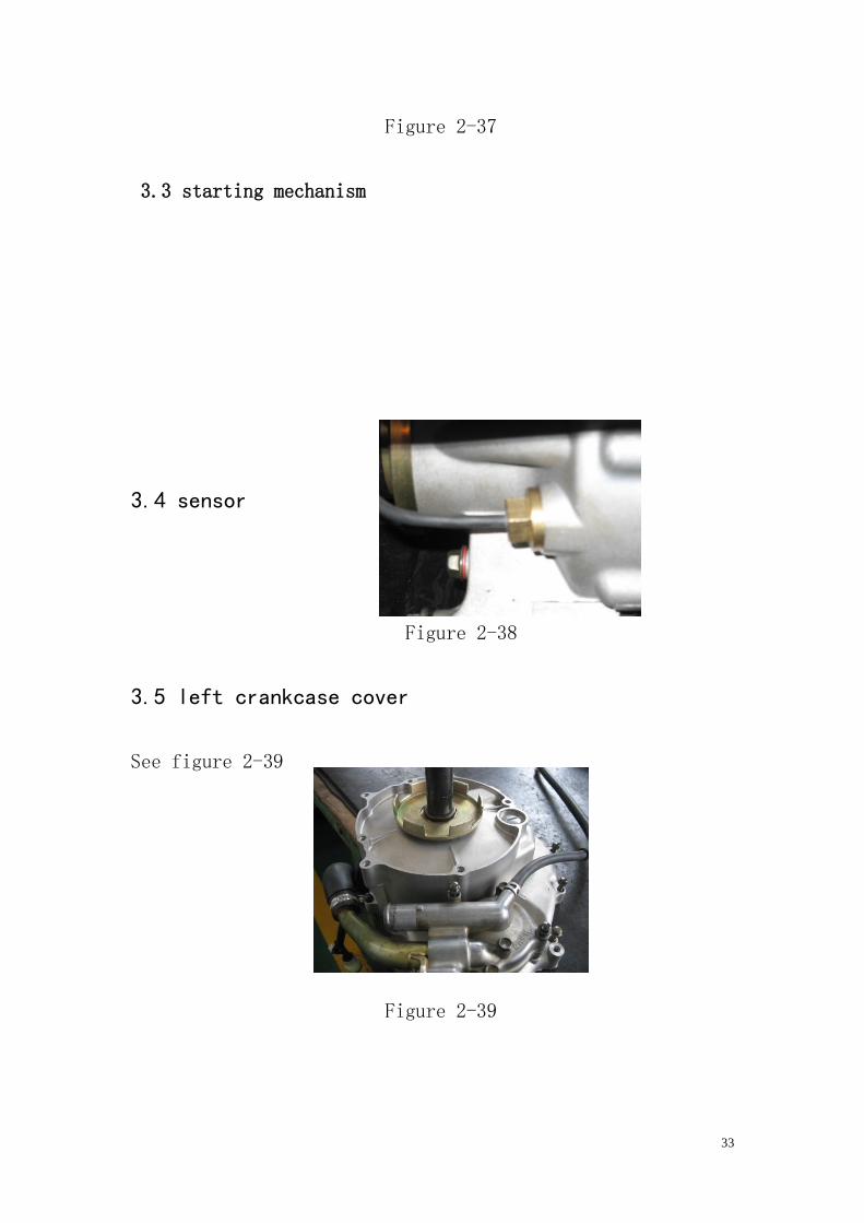
3.4 sensor
Figure 2-38
3.5 left crankcase cover
See figure 2-39
Figure 2-39
34
3. 6 magneto
Remove the stator coil
Remove the pulse coil
Remove the stator with rotor
Stripper. See figure 2-40.
Figure 2-40
Remove the woodruff key. See figure 2-41
Figure 2-41
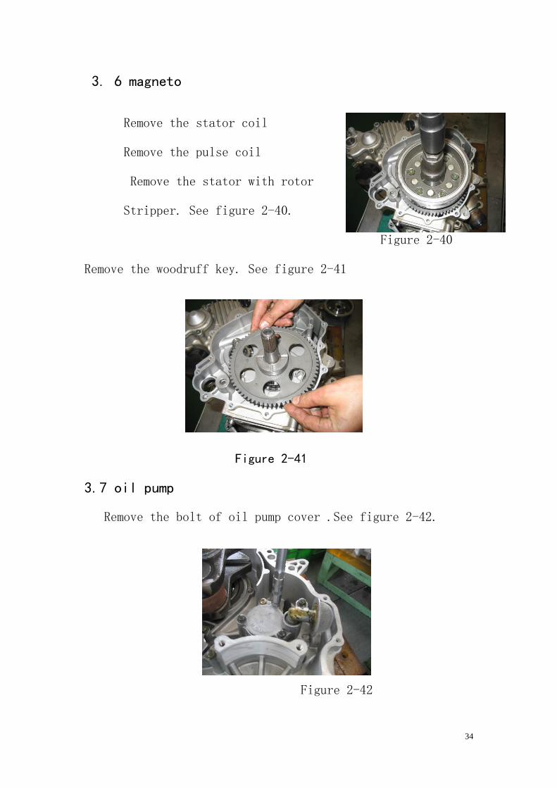
3.7 oil pump
Remove the bolt of oil pump cover .See figure 2-42.
Figure 2-42
35
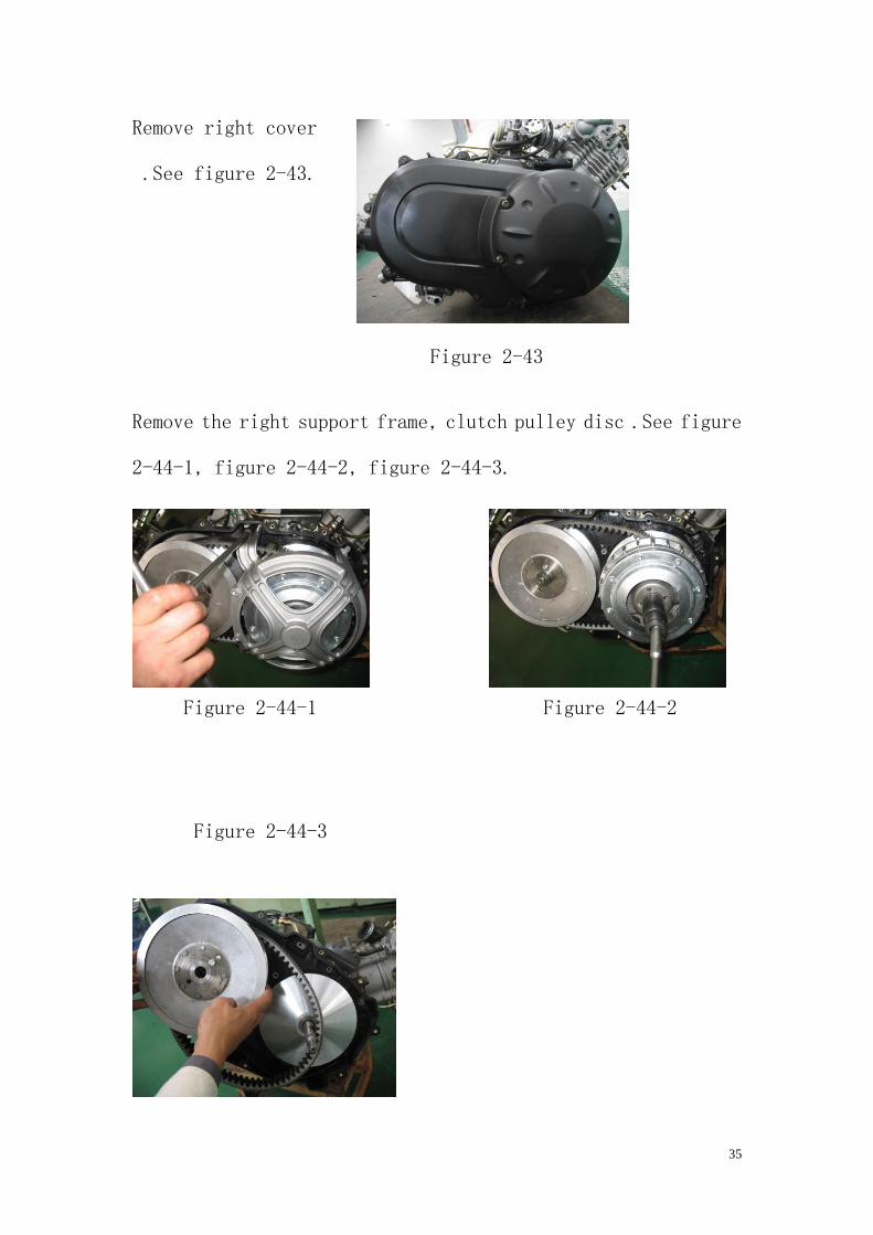
Remove right cover
.See figure 2-43.
Figure 2-43
Remove the right support frame, clutch pulley disc .See figure
2-44-1, figure 2-44-2, figure 2-44-3.
Figure 2-44-1 Figure 2-44-2
Figure 2-44-3
36
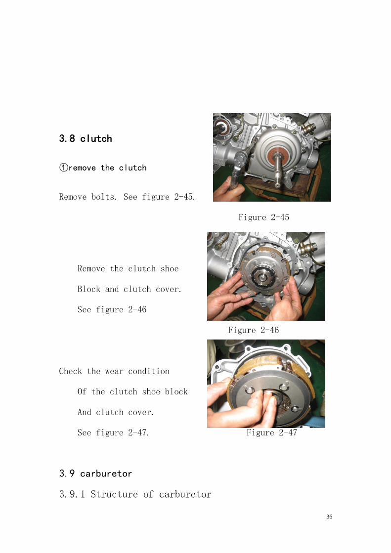
3.8 clutch
①remove the clutch
Remove bolts. See figure 2-45.
Figure 2-45
Remove the clutch shoe
Block and clutch cover.
See figure 2-46
Figure 2-46
Check the wear condition
Of the clutch shoe block
And clutch cover.
See figure 2-47. Figure 2-47
3.9 carburetor
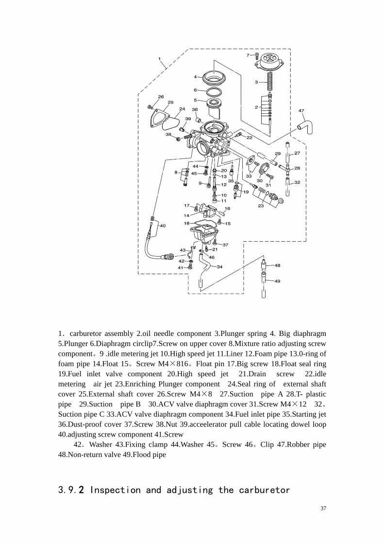
3.9.1 Structure of carburetor
37
1.carburetor assembly 2.oil needle component 3.Plunger spring 4. Big diaphragm
5.Plunger 6.Diaphragm circlip7.Screw on upper cover 8.Mixture ratio adjusting screw
component。9 .idle metering jet 10.High speed jet 11.Liner 12.Foam pipe 13.0-ring of
foam pipe 14.Float 15。Screw M4×816。Float pin 17.Big screw 18.Float seal ring
19.Fuel inlet valve component 20.High speed jet 21.Drain screw 22.idle
metering air jet 23.Enriching Plunger component 24.Seal ring of external shaft
cover 25.External shaft cover 26.Screw M4×8 27.Suction pipe A 28.T- plastic
pipe 29.Suction pipe B 30.ACV valve diaphragm cover 31.Screw M4×12 32。
Suction pipe C 33.ACV valve diaphragm component 34.Fuel inlet pipe 35.Starting jet
36.Dust-proof cover 37.Screw 38.Nut 39.acceelerator pull cable locating dowel loop
40.adjusting screw component 41.Screw
42.Washer 43.Fixing clamp 44.Washer 45。Screw 46。Clip 47.Robber pipe
48.Non-return valve 49.Flood pipe
3.9.2 Inspection and adjusting the carburetor
38
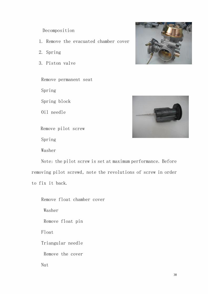
Decomposition
1. Remove the evacuated chamber cover
2. Spring
3. Piston valve
Remove permanent seat
Spring
Spring block
Oil needle
Remove pilot screw
Spring
Washer
Note: the pilot screw is set at maximum performance. Before
removing pilot screwd, note the revolutions of screw in order
to fix it back.
Remove float chamber cover
Washer
Remove float pin
Float
Triangular needle
Remove the cover
Nut
39
0-rings
Spring
Starting plunger
Pilot jet
Check the carburetor body
Float bowl
Oil passage
Gas-fouling block→cleaning
Chap/damage→replace the carburetor assembly
Cleaning steps:
Check the float
damaged→replace
Check the float triangular needle
Triangular needle seat
0-rings
Filter gauze
Damaged/worn out/block→replace
Check the piston valve
crack→replace
Diaphragm
rupture→replace
Piston valve oil stick
40
Bent/worn out→replace
Note: If the piston valve is damaged, inject the petrol into
valve. Replace it when there is oil leakage.
Check the main jet
Main jet
Pilot jet
Pilot screw
0-scrapers
Pilot jet
Bent/worn out/damaged→replace
Gas-fouling block→blow with compressed air
Chassis
Automobile body fastener locking moment of force
Locking spare part
Fastener
specificat
ion
Force
(N.m) Note
F/Rocking shaft and frame M10 45
Disk and the wheel hub M8 23
41
F disk and the front wheel
steering knuckle
M8 33
R disk and the rear wheel
steering knuckle
M10 45
F/R wheel and the wheel hub M10 55
Direction column and direction
stylobate
M14 60
Inside and outside direction
column and direction column
M8 33
Direction and direction column M8 33
F/R bridge gear box and frame M10 55
Front wheel hub and drive shaft M18 120
Engine and connecting board M6 10
The setting base of the engine
and the frame
M10 45
The engine and the setting base M10 45
King pin ball head M10 45
F/R shock absorber and and
frame/rocker shaft
M10 45
Rear steering knuckle and M10 45
42
Other uses M8 23
Other uses M6 10
Other uses M5 6
(The behind torsion revise follow to this table)
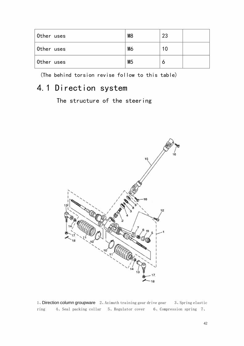
4.1 Direction system
The structure of the steering
1、Direction column groupware 2、Azimuth training gear drive gear 3、Spring elastic
ring 4、Seal packing collar 5、Regulator cover 6、Compression spring 7、
43
Compresses the pad 8、gasket 9、gasket 10、The rubber dirt-proof boot holds the band
11、 Left rubber dirt-proof boot 12、Flange bolt M10×30 13、Azimuth training gear
ball head 14、tension bar locking nut M10 15、Changes the drive shaft part 16、
Flange bolt M8×20 17、Slot nut M12 18、2 Cotter pin3.2×32
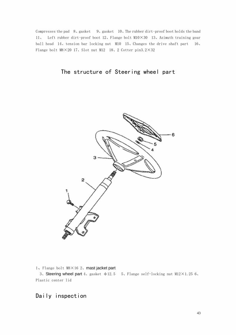
The structure of Steering wheel part
1、Flange bolt M8×16 2、mast jacket part
3、Steering wheel part 4、gasket ф12.5 5、Flange self-locking nut M12×1.25 6、
Plastic center lid
Daily inspection
44
1、Inspect it whether has the crack and the distortion
2、Inspect the ends ball whether becomes less crowded; the
dustproof rubber set does appear the aging, bursts.
3、Inspects the steering wheel whether appears the crack,
flexible and moves.
4、Check the steering wheel to rotate whether nimble, do not
have stagnation.
5、Inspects the torque of the steering wheel whether
obviously increases.
Attention
The steering force cutting which exerts to transfers
in steering wheel outflow boundary is smaller than
245N.
6、Inspects the reverse running clearance whether does surpass
the limited stipulation.
Attention
The reverse running clearance is smaller than 30mm.
If find some problems in the daily inspection, it should be
service immediately to ensure the normal work of the steering
system.
45
Warning: Any quality flaw of the steering system can
cause the serious damage to the driver or send
its death.
4.1.1 Dismantle, inspect, maintain and reinstall the
steering system
4.1.1.1 Dismantle the parts of the steering wheel
1、Takes down the plastic center lid
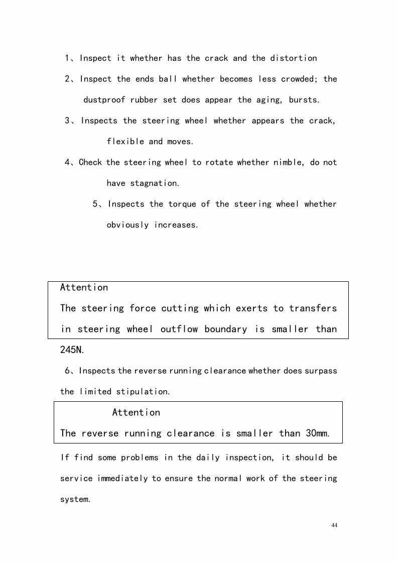
2、Takes down the steering wheel fixing nut, the gasket.
Attached figure 4-1-1.
Attached figure 4-1-1
1. gasketф12.5
2. Flange self-locking nut M12³1.25
3、)Use the special tools (attached figure1.2.14) pull
out the steering wheel. (Attached figure1.2.14)
46
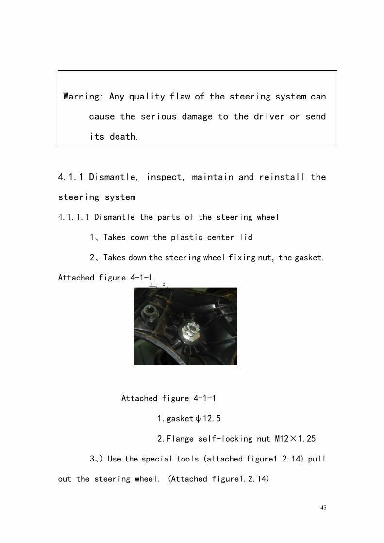
Attached figure4-1-2
1. Steering wheel
4.1.1.2 Inspect the steering wheel
1、 Inspects the steering wheel whether has the hidden
danger which the fissure and possibly breaks, if has,
must replace the steering wheel.
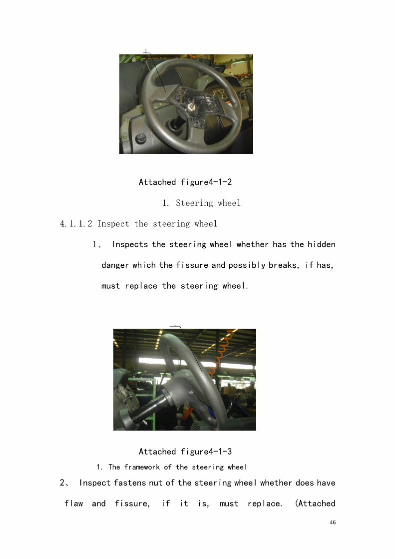
Attached figure4-1-3
1. The framework of the steering wheel
2、 Inspect fastens nut of the steering wheel whether does have
flaw and fissure, if it is, must replace. (Attached
47
figure4-1-3)
3、 Inspects the grip part which is covered by the foam whether
has damaged, if it is, must replace a new steering wheel
4、Check the internal spline between the steering wheel and
steering column whether have damaged, if the attrition is
serious, must replace the steering
Wheel.
The tolerance clearance between the internal spline on
the steering wheel and outer spline on the steering
column is smaller than 0.1MM.
4.1.1.3 Dismantle the steering column parts
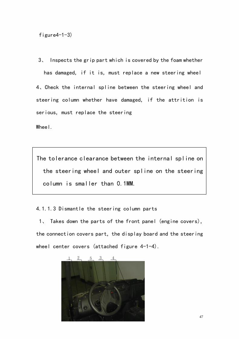
1、 Takes down the parts of the front panel (engine covers),
the connection covers part, the display board and the steering
wheel center covers (attached figure 4-1-4).
48
Attached figure 4-1-4
1. Front panel
2. Connecting cover parts
3. Steering wheel center covers
4. Panel
5. Steering wheel
2、 Take down the steering wheel (Attached figure4-1-4)
3、Loose the M bolt which is on the steering drive axle,
the top of spinet, draws out the cross gimbal.
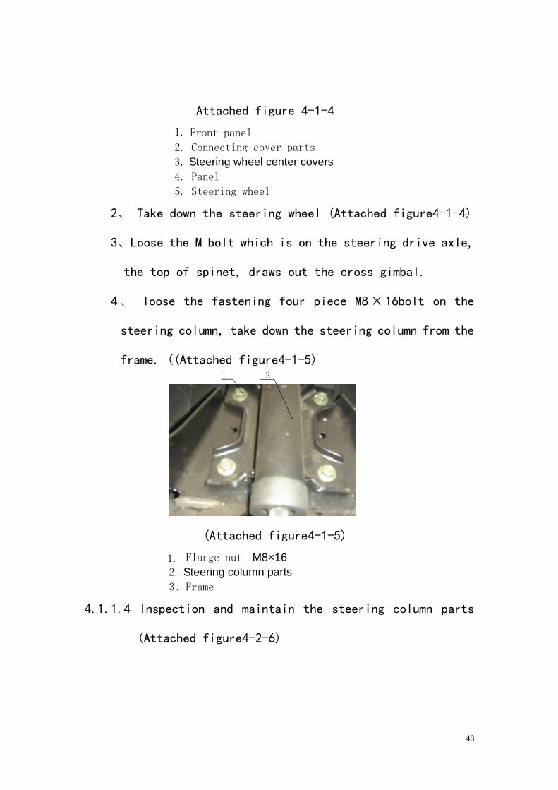
4、 loose the fastening four piece M8³16bolt on the
steering column, take down the steering column from the
frame. ((Attached figure4-1-5)
(Attached figure4-1-5)
1. Flange nut M8×16
2. Steering column parts
3、Frame
4.1.1.4 Inspection and maintain the steering column parts
(Attached figure4-2-6)
49
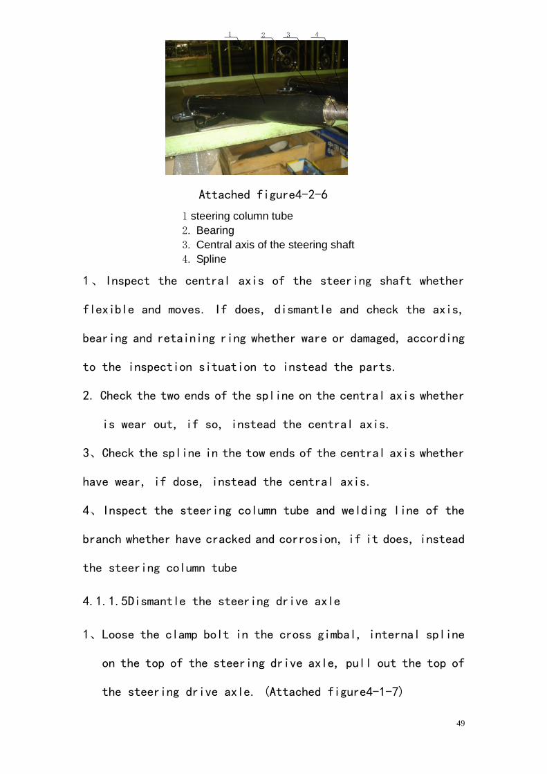
Attached figure4-2-6
1 steering column tube
2. Bearing
3. Central axis of the steering shaft
4. Spline
1、Inspect the central axis of the steering shaft whether
flexible and moves. If does, dismantle and check the axis,
bearing and retaining ring whether ware or damaged, according
to the inspection situation to instead the parts.
2. Check the two ends of the spline on the central axis whether
is wear out, if so, instead the central axis.
3、Check the spline in the tow ends of the central axis whether
have wear, if dose, instead the central axis.
4、Inspect the steering column tube and welding line of the
branch whether have cracked and corrosion, if it does, instead
the steering column tube
4.1.1.5Dismantle the steering drive axle
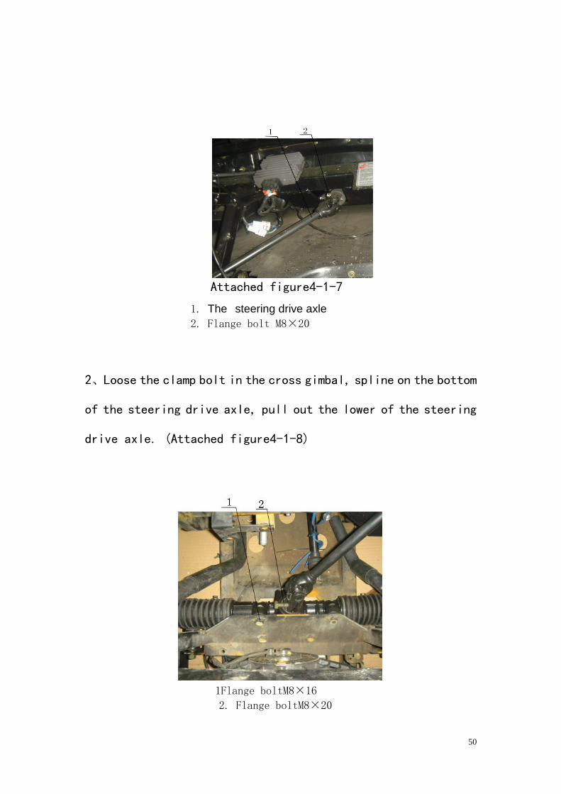
1、Loose the clamp bolt in the cross gimbal, internal spline
on the top of the steering drive axle, pull out the top of
the steering drive axle. (Attached figure4-1-7)
50
Attached figure4-1-7
1. The steering drive axle
2. Flange bolt M8×20
2、Loose the clamp bolt in the cross gimbal, spline on the bottom
of the steering drive axle, pull out the lower of the steering
drive axle. (Attached figure4-1-8)
Attached figure4-1-8
1Flange boltM8×16
2. Flange boltM8×20
51
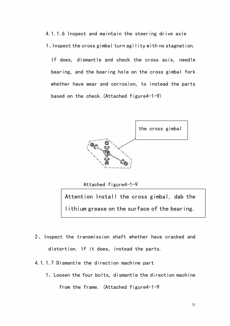
4.1.1.6 Inspect and maintain the steering drive axle
1、Inspect the cross gimbal turn agility with no stagnation.
If does, dismantle and check the cross axis, needle
bearing, and the bearing hole on the cross gimbal fork
whether have wear and corrosion, to instead the parts
based on the check.(Attached figure4-1-9)
Attached figure4-1-9
Attention Install the cross gimbal, dab the
lithium grease on the surface of the bearing.
2、Inspect the transmission shaft whether have cracked and
distortion. If it does, instead the parts.
4.1.1.7 Dismantle the direction machine part
1、Loosen the four bolts, dismantle the direction machine
from the frame. (Attached figure4-1-9
the cross gimbal
52
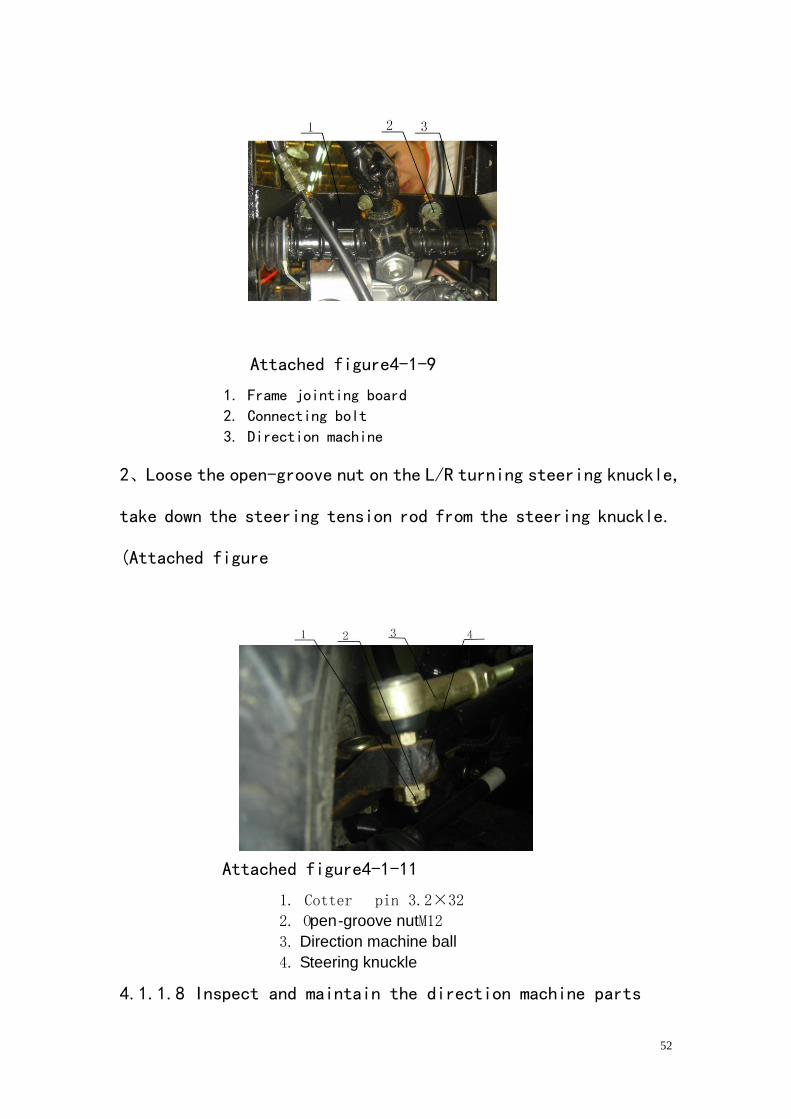
Attached figure4-1-9
1. Frame jointing board
2. Connecting bolt
3. Direction machine
2、Loose the open-groove nut on the L/R turning steering knuckle,
take down the steering tension rod from the steering knuckle.
(Attached figure
Attached figure4-1-11
1. Cotter pin 3.2×32
2. Open-groove nutM12
3. Direction machine ball
4. Steering knuckle
4.1.1.8 Inspect and maintain the direction machine parts
53
1、Inspect the drive of the gear whether angle.
If it is not agile, dismantle the direction machine to
see the gear and rack have wear, instead the parts
according to the inspection.
2、Whether the inspection gear drive reverse gap does
surpass the rating
If it does, adjust the gap and the bolt.
If cannot reduce the gap through the adjustment, instead
the gear, rack
3、Inspects the dustproof rubber set whether gets older and
dehiscence. Replace the older and dehiscence rubber
wrap
4、Inspect the tow balls on the steering tension rod
whether rotates nimbly with no loose. If it is not,
replace the ball.
5、Inspects the dustproof rubber set of the ball whether
gets older and dehiscence. Replace the older rand
dehiscence rubber wrap.
6、Inspect the steering tension rod whether have cracked
and distortion. If it does, through the sizing repair
Warning: Do not use the welding to repair the steering
tension rod.
54
Attention
1、When replace the rubber set of the ball, must enter
1/2 volume in lithium grease in to the rubber.
2、When replace the direction mechanism, cleaning all
the parts, and daub the lithium grease in to the
movement.
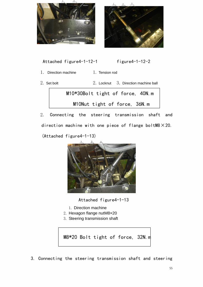
4.1.1.3Reinstalls the steering system parts
1. Connecting the direction machine with four pieces bolt M10
³30 on the frame, then use tow pieces of locknut to connect
the direction machine ball and the rod. (Attached
figure4-1-12-1)
Figure4-1-12-2
Attention: continue to use
the hidden danger Ball
pin may causes the serious
accident or the death.
55
Attached figure4-1-12-1 figure4-1-12-2
1. Direction machine 1. Tension rod
2. Set bolt 2. Locknut 3. Direction machine ball
M10*30Bolt tight of force, 40N.m
M10Nut tight of force, 36N.m
2. Connecting the steering transmission shaft and
direction machine with one piece of flange boltM8³20.
(Attached figure4-1-13)
Attached figure4-1-13
1. Direction machine
2. Hexagon flange nutM8×20
3. Steering transmission shaft
M8*20 Bolt tight of force, 32N.m
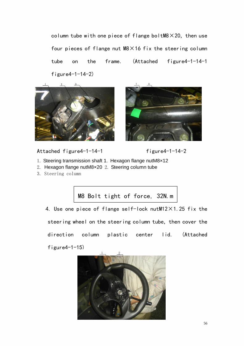
3. Connecting the steering transmission shaft and steering
56
column tube with one piece of flange boltM8³20, then use
four pieces of flange nut M8³16 fix the steering column
tube on the frame. (Attached figure4-1-14-1
figure4-1-14-2)
Attached figure4-1-14-1 figure4-1-14-2
1. Steering transmission shaft 1. Hexagon flange nutM8×12
2. Hexagon flange nutM8×20 2. Steering column tube
3. Steering column
M8 Bolt tight of force, 32N.m
4. Use one piece of flange self-lock nutM12³1.25 fix the
steering wheel on the steering column tube, then cover the
direction column plastic center lid. (Attached
figure4-1-15)
57
Attached figure4-1-15
1. Flange self-lock nutM12×1.25
2. Steering wheel
Steering wheel tight of force, 40N.m
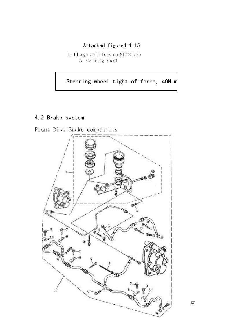
4.2 Brake system
Front Disk Brake components
58
1、Brake pump assembly 2、flange boltM6×20 3、tape3(L=150) 4、)
tape4 (L=200) 5、tape3(L=150) 6、flange boltM6×30 7、flange boltM6
×20 8、band 9、flange boltM6×20 10、brake tube seat 11、Brake components
4.2.1 Preparation for inspection before the maintenance of the
brake system.
。Brake system is crucial to the life safety of the operator
and therefore must be periodically inspected and maintained.
This vehicle uses the double return route hydraulic pressure
disc brake system. Please follow the tips of inspection as
below.
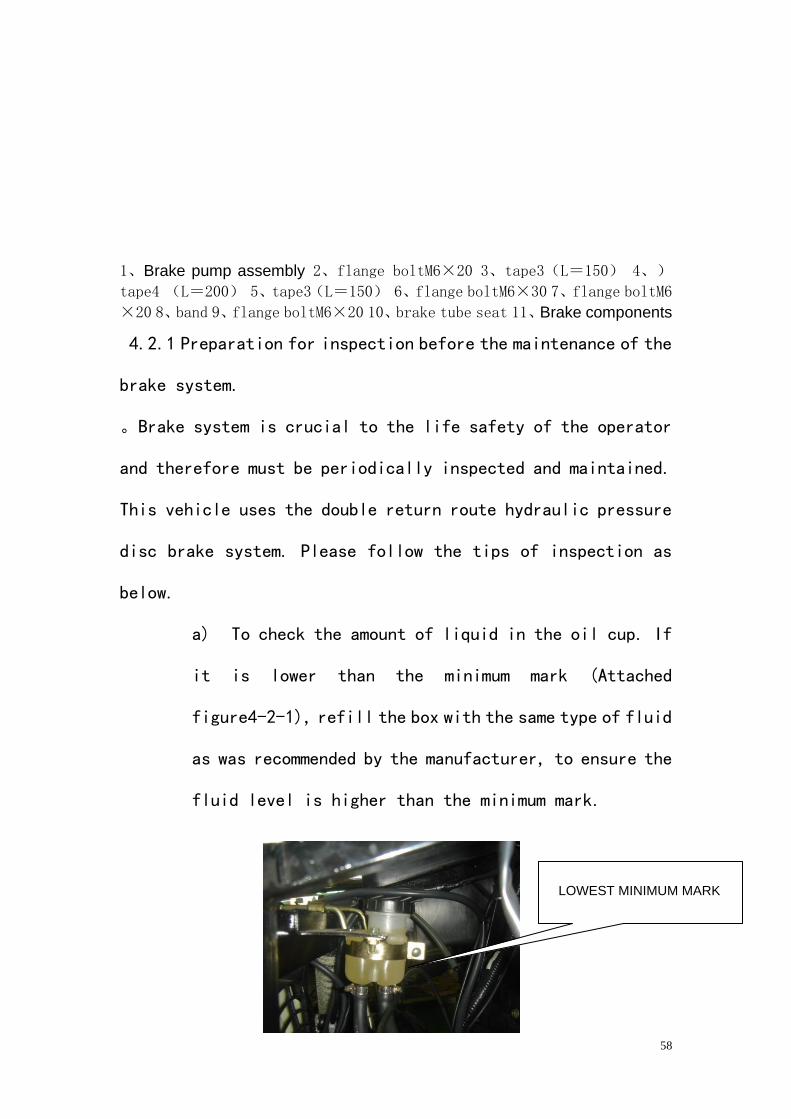
a) To check the amount of liquid in the oil cup. If
it is lower than the minimum mark (Attached
figure4-2-1), refill the box with the same type of fluid
as was recommended by the manufacturer, to ensure the
fluid level is higher than the minimum mark.
LOWEST MINIMUM MARK
59
Attached figure4-2-1
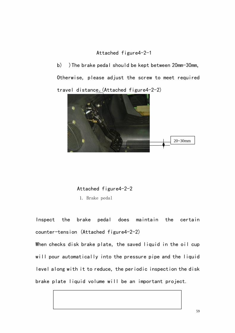
b) )The brake pedal should be kept between 20mm-30mm,
Otherwise, please adjust the screw to meet required
travel distance.(Attached figure4-2-2)
Attached figure4-2-2
1. Brake pedal
Inspect the brake pedal does maintain the certain
counter-tension (Attached figure4-2-2)
When checks disk brake plate, the saved liquid in the oil cup
will pour automatically into the pressure pipe and the liquid
level along with it to reduce, the periodic inspection the disk
brake plate liquid volume will be an important project.
20~30mm
60
Attention, must use DOT4 Brake Fluid
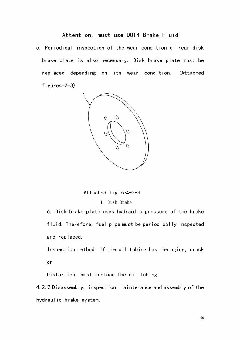
5. Periodical inspection of the wear condition of rear disk
brake plate is also necessary. Disk brake plate must be
replaced depending on its wear condition. (Attached
figure4-2-3)
Attached figure4-2-3
1、Disk Brake
6. Disk brake plate uses hydraulic pressure of the brake
fluid. Therefore, fuel pipe must be periodically inspected
and replaced.
Inspection method: If the oil tubing has the aging, crack
or
Distortion, must replace the oil tubing.
4.2.2 Disassembly, inspection, maintenance and assembly of the
hydraulic brake system.
61
4.2.2.1 Disassembly of front disk brake plate and the brake
plate clip parts.
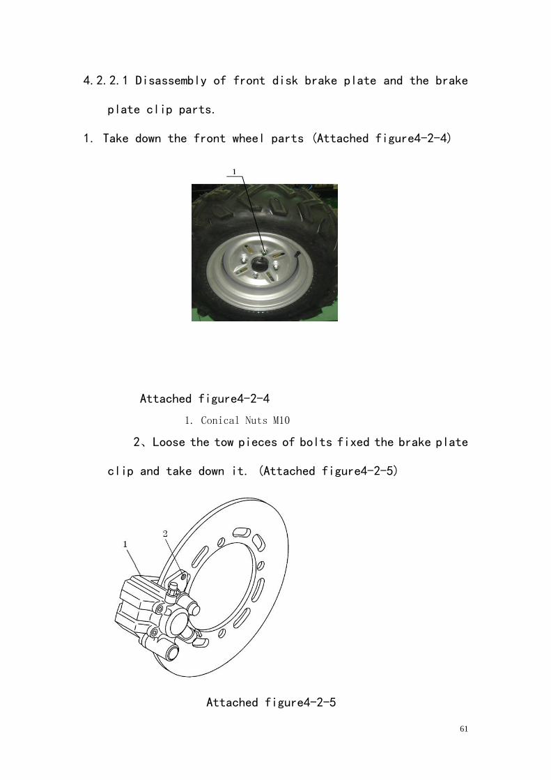
1. Take down the front wheel parts (Attached figure4-2-4)
Attached figure4-2-4
1. Conical Nuts M10
2、Loose the tow pieces of bolts fixed the brake plate
clip and take down it. (Attached figure4-2-5)
Attached figure4-2-5
62
1. Brake plate clip
2. Bolt
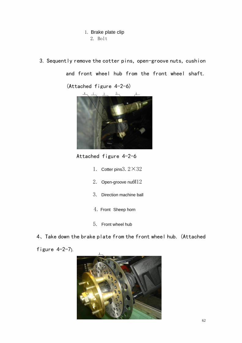
3. Sequently remove the cotter pins, open-groove nuts, cushion
and front wheel hub from the front wheel shaft.
(Attached figure 4-2-6)
Attached figure 4-2-6
1. Cotter pins3.2×32
2. Open-groove nutM12
3. Direction machine ball
4. Front Sheep horn
5. Front wheel hub
4、Take down the brake plate from the front wheel hub. (Attached
figure 4-2-7).
63
Attached figure4-2-7
1. Front disk brake plate
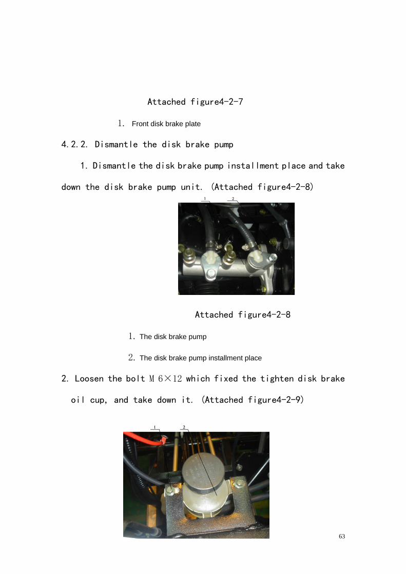
4.2.2. Dismantle the disk brake pump
1. Dismantle the disk brake pump installment place and take
down the disk brake pump unit. (Attached figure4-2-8)
Attached figure4-2-8
1. The disk brake pump
2. The disk brake pump installment place
2. Loosen the bolt M 6×12 which fixed the tighten disk brake
oil cup, and take down it. (Attached figure4-2-9)
64
Attached figure4-2-9
1. Hexagon BoltM6×12
2. Disk brake oil cup
4.2.2.3 Dismantle the rear brake plate clip and the rear disk
brake plate
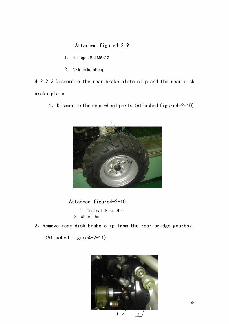
1、Dismantle the rear wheel parts (Attached figure4-2-10)
Attached figure4-2-10
1. Conical Nuts M10 2. Wheel hub
2、Remove rear disk brake clip from the rear bridge gearbox.
(Attached figure4-2-11)
65
Attached figure4-2-11
1、Rear Disk Brake Clip
2、Hexagon BoltM10×30
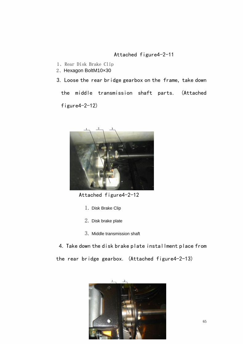
3. Loose the rear bridge gearbox on the frame, take down
the middle transmission shaft parts. (Attached
figure4-2-12)
Attached figure4-2-12
1. Disk Brake Clip
2. Disk brake plate
3. Middle transmission shaft
4. Take down the disk brake plate installment place from
the rear bridge gearbox. (Attached figure4-2-13)
66
Attached figure4-2-13
1. The disk brake plate installment place
2. The rear disk brake plate
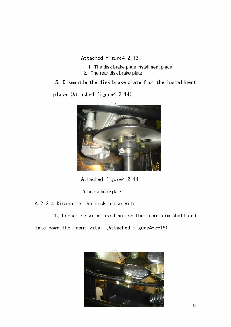
5. Dismantle the disk brake plate from the installment
place (Attached figure4-2-14)
Attached figure4-2-14
1. Rear disk brake plate
4.2.2.4 Dismantle the disk brake vita
1、Loose the vita fixed nut on the front arm shaft and
take down the front vita. (Attached figure4-2-15).
67
Attached figure4-2-15
1. Hexagon BoltM6×12
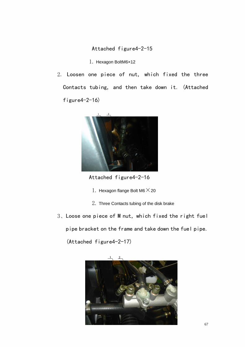
2. Loosen one piece of nut, which fixed the three
Contacts tubing, and then take down it. (Attached
figure4-2-16)
Attached figure4-2-16
1. Hexagon flange Bolt M6×20
2. Three Contacts tubing of the disk brake
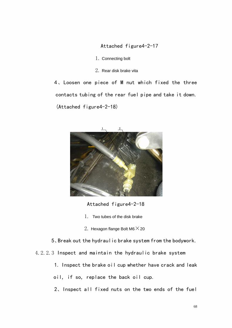
3、Loose one piece of M nut, which fixed the right fuel
pipe bracket on the frame and take down the fuel pipe.
(Attached figure4-2-17)
68
Attached figure4-2-17
1. Connecting bolt
2. Rear disk brake vita
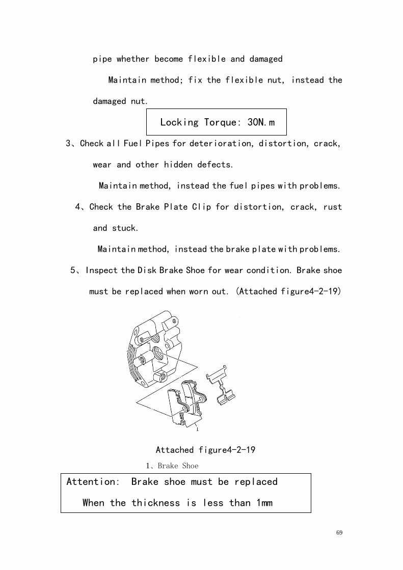
4、Loosen one piece of M nut which fixed the three
contacts tubing of the rear fuel pipe and take it down.
(Attached figure4-2-18)
Attached figure4-2-18
1. Two tubes of the disk brake
2. Hexagon flange Bolt M6×20
5、Break out the hydraulic brake system from the bodywork.
4.2.2.3 Inspect and maintain the hydraulic brake system
1. Inspect the brake oil cup whether have crack and leak
oil, if so, replace the back oil cup.
2、Inspect all fixed nuts on the two ends of the fuel
69
pipe whether become flexible and damaged
Maintain method; fix the flexible nut, instead the
damaged nut.
Locking Torque: 30N.m
3、Check all Fuel Pipes for deterioration, distortion, crack,
wear and other hidden defects.
Maintain method, instead the fuel pipes with problems.
4、Check the Brake Plate Clip for distortion, crack, rust
and stuck.
Maintain method, instead the brake plate with problems.
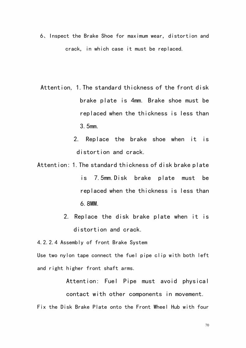
5、Inspect the Disk Brake Shoe for wear condition. Brake shoe
must be replaced when worn out. (Attached figure4-2-19)
Attached figure4-2-19
1、Brake Shoe
Attention: Brake shoe must be replaced
When the thickness is less than 1mm
70
6、Inspect the Brake Shoe for maximum wear, distortion and
crack, in which case it must be replaced.
Attention, 1.The standard thickness of the front disk
brake plate is 4mm. Brake shoe must be
replaced when the thickness is less than
3.5mm.
2. Replace the brake shoe when it is
distortion and crack.
Attention: 1.The standard thickness of disk brake plate
is 7.5mm.Disk brake plate must be
replaced when the thickness is less than
6.8MM.
2. Replace the disk brake plate when it is
distortion and crack.
4.2.2.4 Assembly of front Brake System
Use two nylon tape connect the fuel pipe clip with both left
and right higher front shaft arms.
Attention: Fuel Pipe must avoid physical
contact with other components in movement.
Fix the Disk Brake Plate onto the Front Wheel Hub with four
71
pieces of M Bolts.
Attention: grease the bolt with thread glue when
fastening.
Fastening Torque of the Bolt: 22 N.m -28N.m
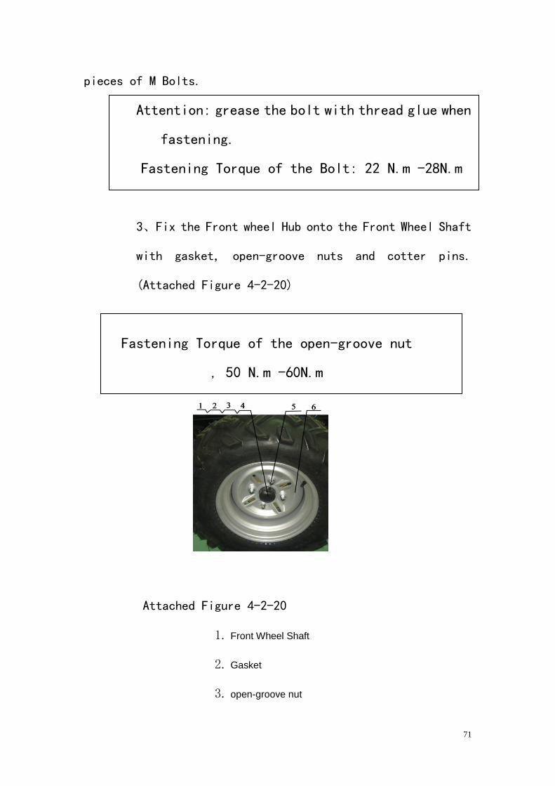
3、Fix the Front wheel Hub onto the Front Wheel Shaft
with gasket, open-groove nuts and cotter pins.
(Attached Figure 4-2-20)
Fastening Torque of the open-groove nut
, 50 N.m -60N.m
Attached Figure 4-2-20
1. Front Wheel Shaft
2. Gasket
3. open-groove nut
72
4. Cotter pin3.2×32
5. Conical NutM10
6. Front wheel Hub
4. Fix the Plate Clip onto Front Turning Joint with four pieces
of M10×22 Bolts.
Fastening Torque: 18 N.m --22N.m
5、Assemble Front Wheel Components onto Front Wheel Hub with
four pieces of GB/T802M10 Conical Nuts.
(AttachedFigure4-2-20)
Fastening Torque of Conical Nut: 50 N.m -55N.m
6. Fix Front Disk Brake Pump onto the frame with two pieces of
M M10×55 bolts.
Fastening Torque of the bolt, 40N.m
Attention: Do not operate the vehicle immediately after
assembling the brake system. Please apply the Brake
Lever several times to fully engage the Disk Brake Plate
and have the Brake Fluid circulating before riding the
73
vehicle.
7.。Fix Disk Brake Plate onto the Bottom Seat with six pieces
of M8 Bolts.
Attention, Grease the bolt with thread glue when
fastening
Fastening Torque of bolt: 22 N.m -28N.m
8. Mount the Bottom Seat of disk brake plate and rear
middle transmission shaft and Rear Bridge onto the
rear bridge. (AttachedFigure4-2-12)
9. Mount the Disk Brake Clip onto Rear Bridge with two pieces
of M bolt.
Fastening Torque, 18 N.m -12 N.m
10、Sequently fix the F/R three contacts of front fuel pipe
F/R fuel pipe.
4.2.3 Dismantle, inspect, maintain and inspect the Parking
system
4.2.3.1 Dismantle the parking system
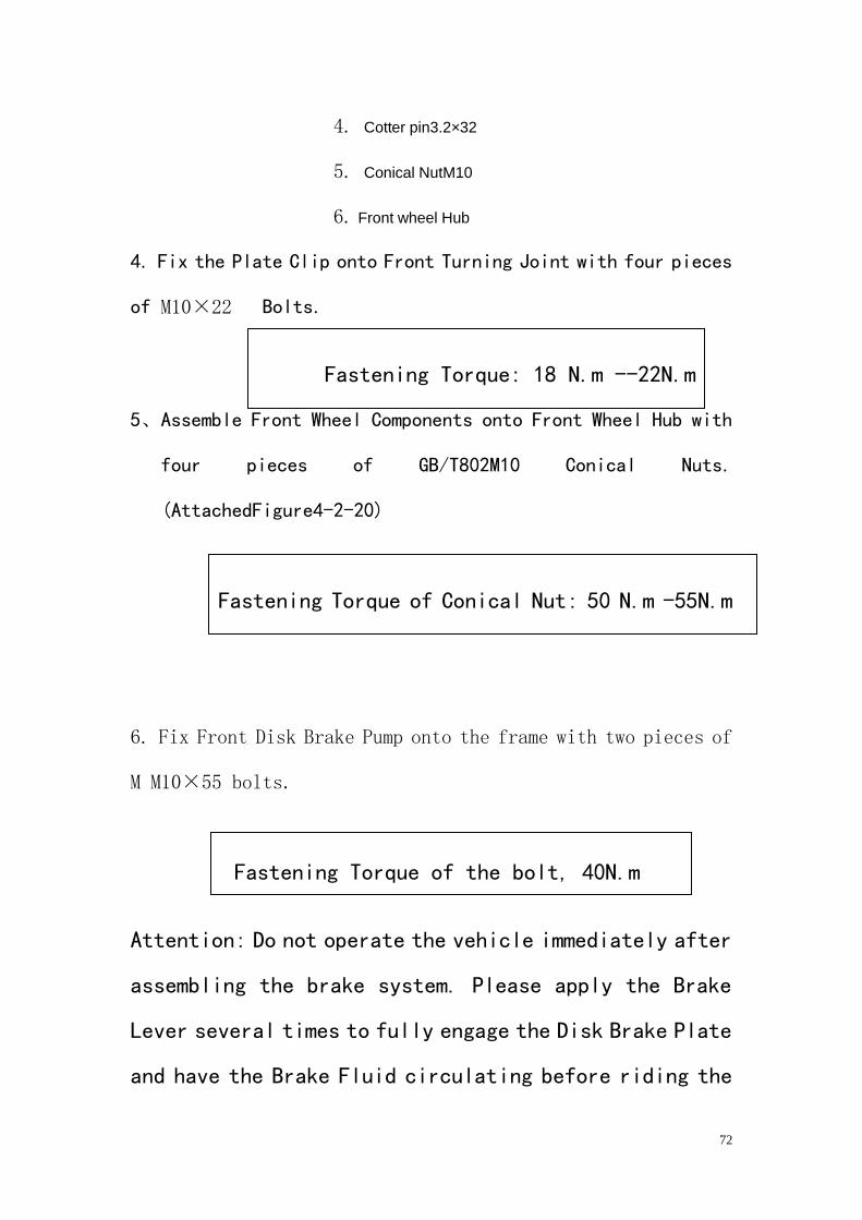
1、Take down the central lid(AttachedFigure4-2-21)
74
AttachedFigure4-2-21
1. The Central lid
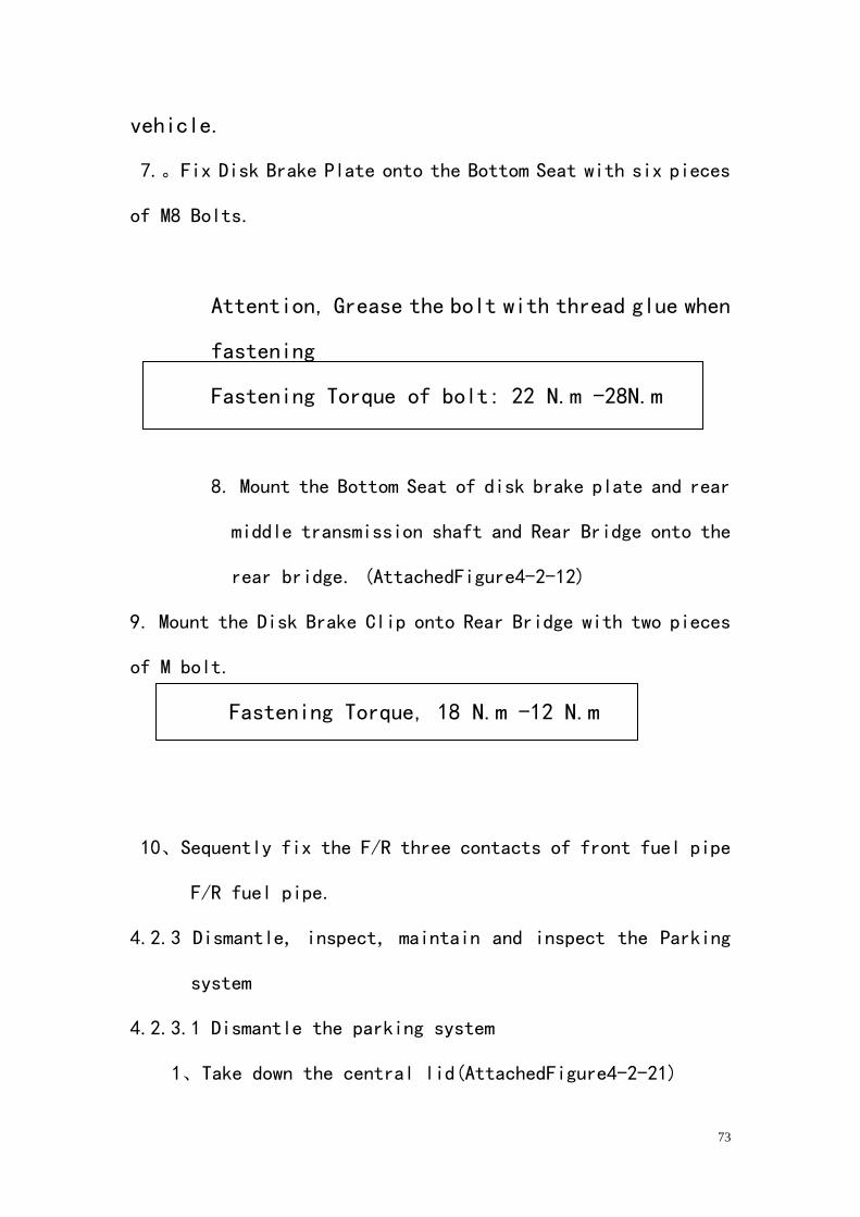
2、Loose the two pieces M bolt, take down the parking handle.
(AttachedFigure4-2-22)
AttachedFigure4-2-22
1. Parking handle
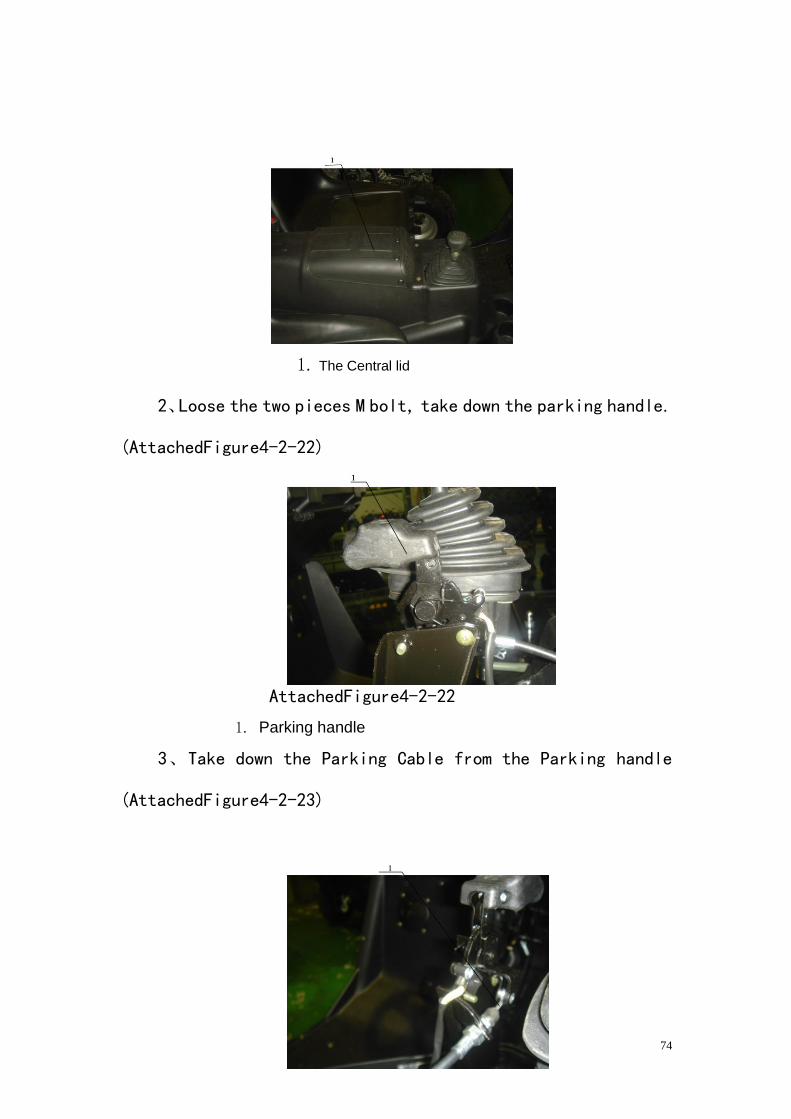
3、Take down the Parking Cable from the Parking handle
(AttachedFigure4-2-23)
75
AttachedFigure4-2-23
1. Parking Cable
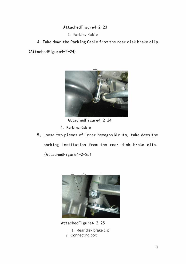
4. Take down the Parking Cable from the rear disk brake clip.
(AttachedFigure4-2-24)
AttachedFigure4-2-24
1. Parking Cable
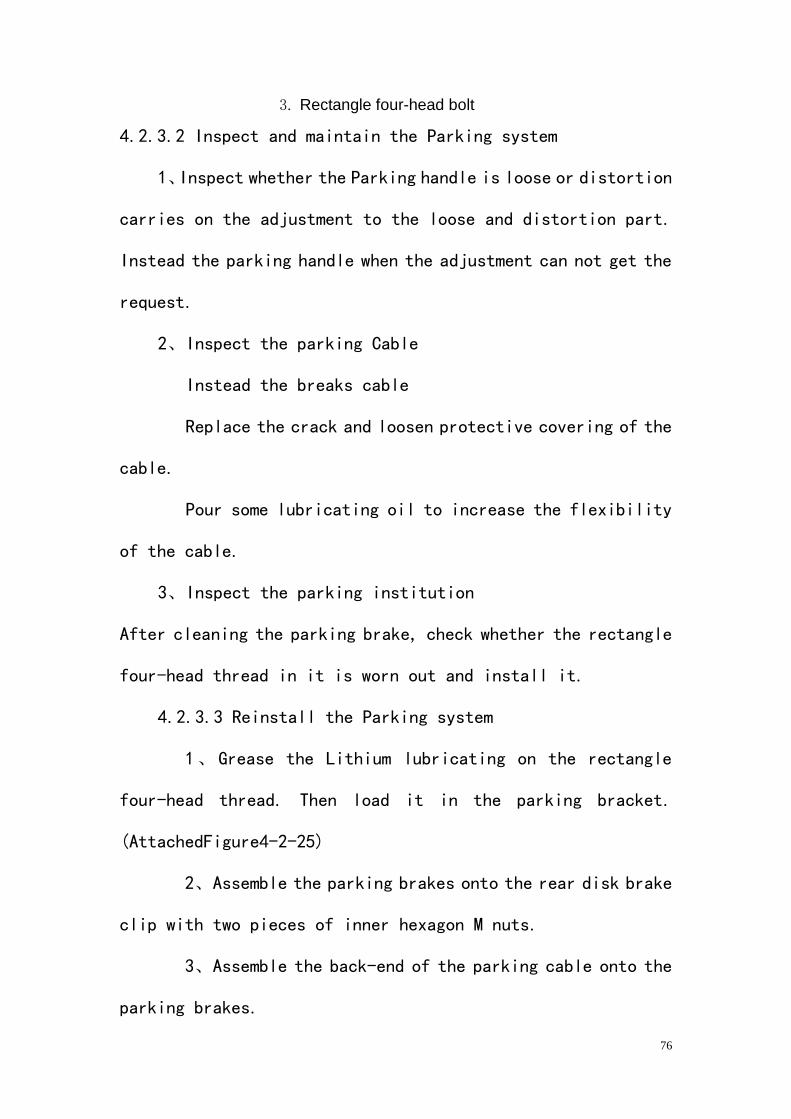
5、Loose two pieces of inner hexagon M nuts, take down the
parking institution from the rear disk brake clip.
(AttachedFigure4-2-25)
AttachedFigure4-2-25
1. Rear disk brake clip
2. Connecting bolt
76
3. Rectangle four-head bolt
4.2.3.2 Inspect and maintain the Parking system
1、Inspect whether the Parking handle is loose or distortion
carries on the adjustment to the loose and distortion part.
Instead the parking handle when the adjustment can not get the
request.
2、Inspect the parking Cable
Instead the breaks cable
Replace the crack and loosen protective covering of the
cable.
Pour some lubricating oil to increase the flexibility
of the cable.
3、Inspect the parking institution
After cleaning the parking brake, check whether the rectangle
four-head thread in it is worn out and install it.
4.2.3.3 Reinstall the Parking system
1、Grease the Lithium lubricating on the rectangle
four-head thread. Then load it in the parking bracket.
(AttachedFigure4-2-25)
2、Assemble the parking brakes onto the rear disk brake
clip with two pieces of inner hexagon M nuts.
3、Assemble the back-end of the parking cable onto the
parking brakes.
77
4、Assemble the parking handle onto the frame with two
M nuts.
5、Assemble the front of the parking cable onto the
parking handle.
6、Adjust the inner hexagon nuts until the rear brake
shoe exactly contact with the rear disk brake plate,
then finish the adjustment with lock the inner
hexagon nuts with spanner,
Attention: after the adjustment, the UTV can
parking stabilized in the 12° pitch with the
fully loaded. (The total quality is 920KG)
4.3 Wheel and Tire parts
4.3.1 Preparation for maintenance of wheel.
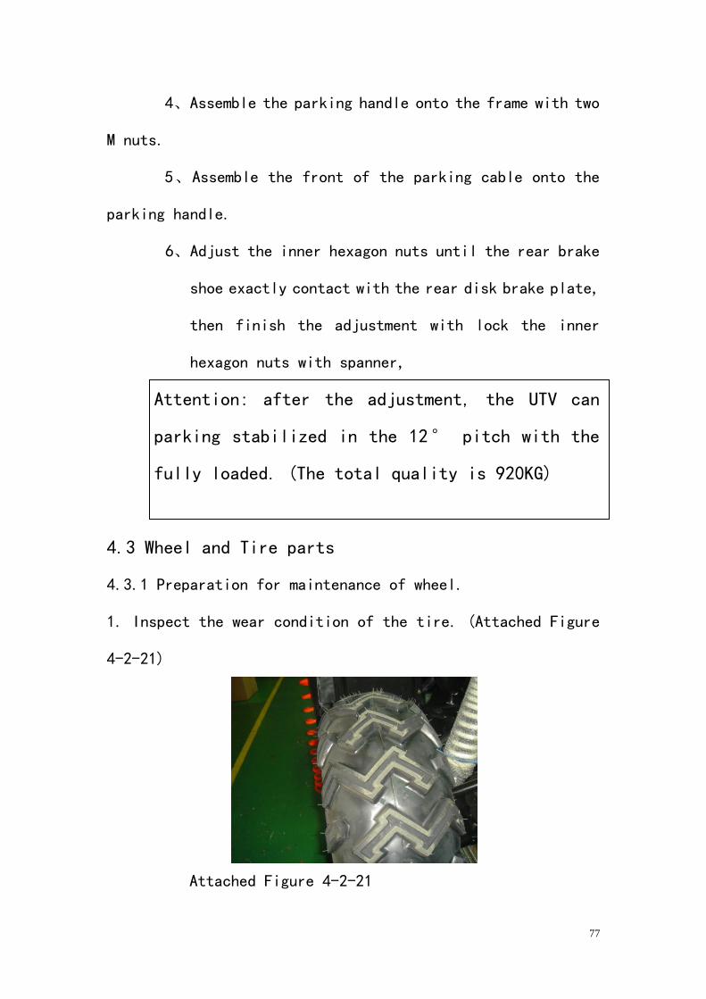
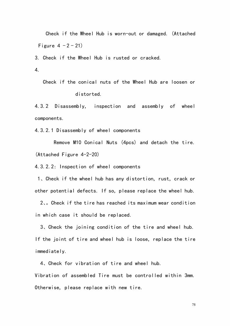
1. Inspect the wear condition of the tire. (Attached Figure
4-2-21)
Attached Figure 4-2-21
78
Check if the Wheel Hub is worn-out or damaged. (Attached
Figure 4 - 2 - 21)
3. Check if the Wheel Hub is rusted or cracked.
4.
Check if the conical nuts of the Wheel Hub are loosen or
distorted.
4.3.2 Disassembly, inspection and assembly of wheel
components.
4.3.2.1 Disassembly of wheel components
Remove M10 Conical Nuts (4pcs) and detach the tire.
(Attached Figure 4-2-20)
4.3.2.2: Inspection of wheel components
1、Check if the wheel hub has any distortion, rust, crack or
other potential defects. If so, please replace the wheel hub.
2、。Check if the tire has reached its maximum wear condition
in which case it should be replaced.
3、Check the joining condition of the tire and wheel hub.
If the joint of tire and wheel hub is loose, replace the tire
immediately.
4、Check for vibration of tire and wheel hub.
Vibration of assembled Tire must be controlled within 3mm.
Otherwise, please replace with new tire.
79
Remove the tire for vibration test of the wheel hub. Should the
vibration exceed 1.2mm, the wheel hub must be
replaced.
5、Inspect the four conical bores on the wheel hub. In occasion
of angular distortion or wear, the wheel hub must
be replaced.
The angle of the conical bores is 60°
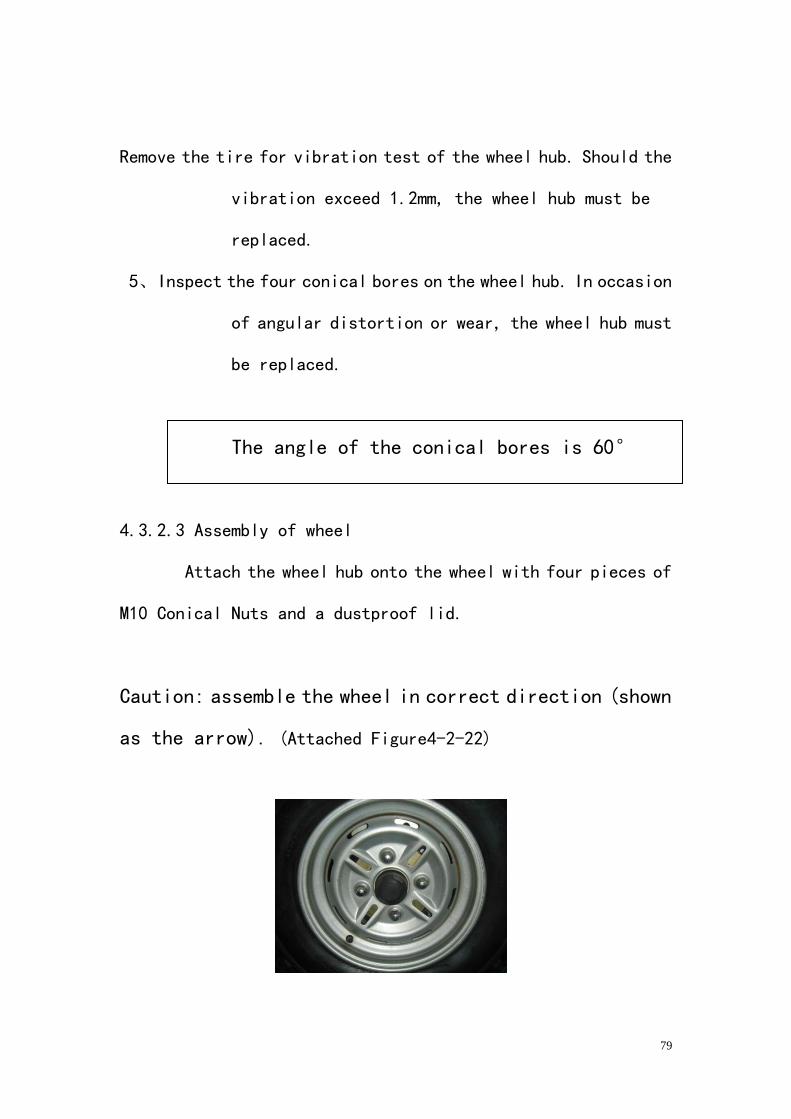
4.3.2.3 Assembly of wheel
Attach the wheel hub onto the wheel with four pieces of
M10 Conical Nuts and a dustproof lid.
Caution: assemble the wheel in correct direction (shown
as the arrow). (Attached Figure4-2-22)
80
(Attached Figure4-2-22)
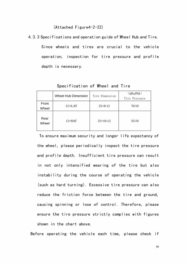
4.3.3 Specifications and operation guide of Wheel Hub and Tire.
Since wheels and tires are crucial to the vehicle
operation, inspection for tire pressure and profile
depth is necessary.
Specification of Wheel and Tire
Wheel Hub Dimension Tyre Dimension (kPa/PSI)
Tire Pressure
Front
Wheel 12×6.AT 25×8-12 70/10
Rear
Wheel
12×8AT 25×10-12 35/10
To ensure maximum security and longer life expectancy of
the wheel, please periodically inspect the tire pressure
and profile depth. Insufficient tire pressure can result
in not only intensified wearing of the tire but also
instability during the course of operating the vehicle
(such as hard turning). Excessive tire pressure can also
reduce the friction force between the tire and ground,
causing spinning or lose of control. Therefore, please
ensure the tire pressure strictly complies with figures
shown in the chart above.
Before operating the vehicle each time, please check if
81
profile depth of the tire is over worn, which might result in
spinning, instability, lose of control and other potential
security risk of the vehicle.
Warnning:
The profile depth falls below 3mm, please replace
the tire immediately.
(AttacheFigure4-2-13)
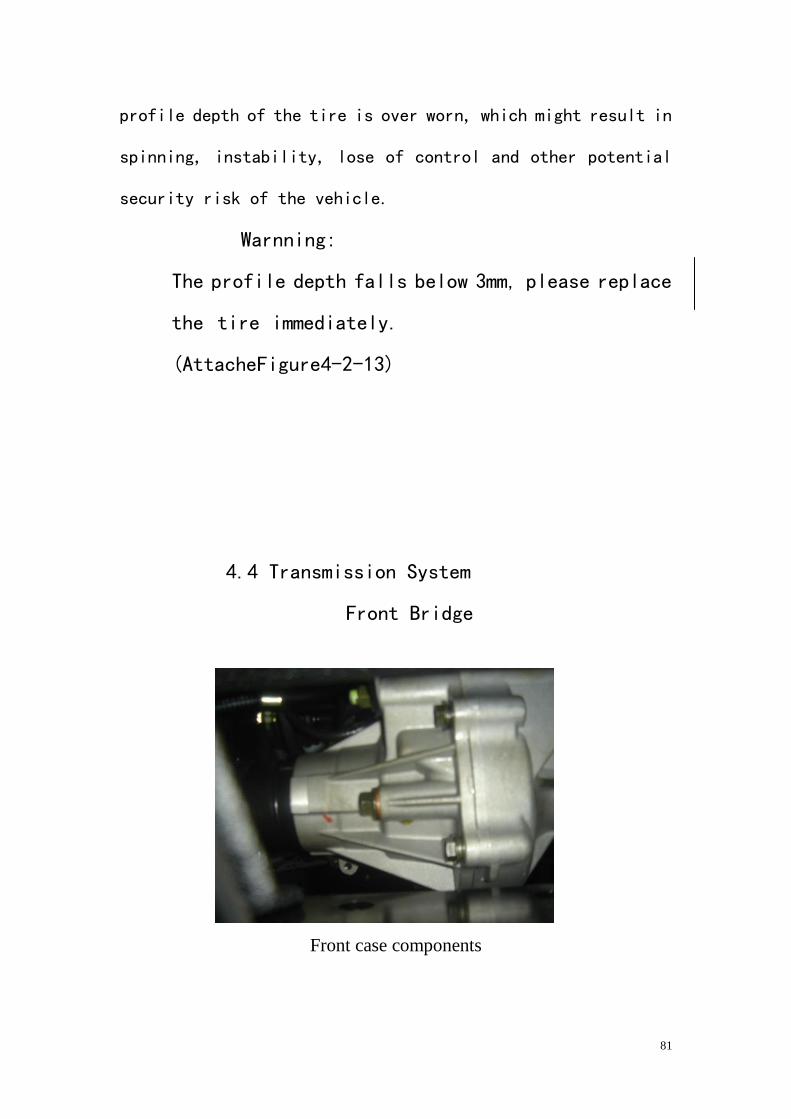
4.4 Transmission System
Front Bridge
Front case components
82
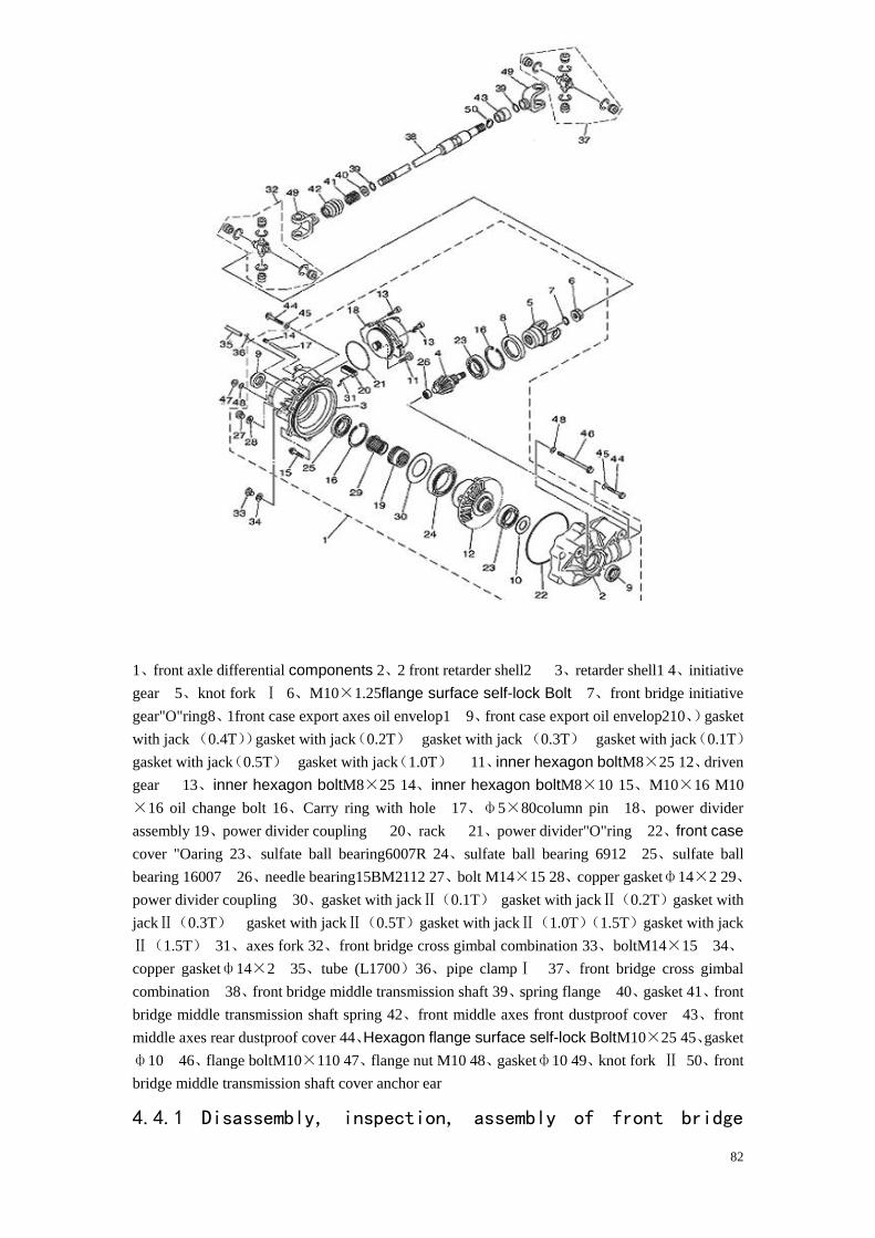
1、front axle differential components 2、2 front retarder shell2 3、retarder shell1 4、initiative
gear 5、knot fork Ⅰ 6、M10×1.25flange surface self-lock Bolt 7、front bridge initiative
gear"O"ring8、1front case export axes oil envelop1 9、front case export oil envelop210、)gasket
with jack (0.4T))gasket with jack(0.2T) gasket with jack (0.3T) gasket with jack(0.1T)
gasket with jack(0.5T) gasket with jack(1.0T) 11、inner hexagon boltM8×25 12、driven
gear 13、inner hexagon boltM8×25 14、inner hexagon boltM8×10 15、M10×16 M10
×16 oil change bolt 16、Carry ring with hole 17、ф5×80column pin 18、power divider
assembly 19、power divider coupling 20、rack 21、power divider"O"ring 22、front case
cover "Oaring 23、sulfate ball bearing6007R 24、sulfate ball bearing 6912 25、sulfate ball
bearing 16007 26、needle bearing15BM2112 27、bolt M14×15 28、copper gasketф14×2 29、
power divider coupling 30、gasket with jackⅡ(0.1T) gasket with jackⅡ(0.2T)gasket with
jackⅡ(0.3T) gasket with jackⅡ(0.5T)gasket with jackⅡ(1.0T)(1.5T)gasket with jack
Ⅱ(1.5T) 31、axes fork 32、front bridge cross gimbal combination 33、boltM14×15 34、
copper gasketф14×2 35、tube (L1700)36、pipe clampⅠ 37、front bridge cross gimbal
combination 38、front bridge middle transmission shaft 39、spring flange 40、gasket 41、front
bridge middle transmission shaft spring 42、front middle axes front dustproof cover 43、front
middle axes rear dustproof cover 44、Hexagon flange surface self-lock BoltM10×25 45、gasket
ф10 46、flange boltM10×110 47、flange nut M10 48、gasketф10 49、knot fork Ⅱ 50、front
bridge middle transmission shaft cover anchor ear
4.4.1 Disassembly, inspection, assembly of front bridge
83
components (Reference the front bridge assembly, the figure of
the front box parts).
4.4.1.1 Preparation for disassembly and maintenance of front
bridge components.
1.。Check if the connection between wheel hub and conical
nuts is reliable and not loose.
2、If there is any distortion on the front wheel hub; the
wheel hub must be replaced immediately.
3. Whether the spare part does coordinate with the sheep horn,
whether the sheep horn bearing exists stagnation, check for
noise, if bearing is unreliable, and must disassemble the front
bridge
Assembly (refer to the front bridge assembly, the figure of the
front box parts), then instead the bearing to use. Check the
sheep horn whether have rupture, if so, instead it.
4. Whether the constant velocity joint does coordinate, to be
correct to the position; If is not correct or the coordination
is not
Good causes to the position hits the tooth and the
different sound,
Must dismantle it, installs and driving agine after the
position correct.
84
5. Check if there exists any slip thread on the
open-groove nut.
6. Disassemble the front bridge transmission box parts, check
each joggle whether contraposition and right, the joggle have
no intervene.
7. Whether the oil nozzle does stop up, if so, first to use the
needle to poke the material if it will not be able to solved,
replace the oil nozzle to install the original position of the
front box.
8. If there are any problems with the sensor, it must be
inspected and maintained by the special serviceman.
9. The gear is easy to wear out, and it is in the
transmission system.
4.1.2 Disassemble, inspection and assembly of the front bridge
4.4.2.1 Disassemble the front bridge
1. Take down the left and right front wheel parts.
2. Sequently remove the front disk brake clip, cotter pin,
open-groove nut, cushion and front wheel hub.
3、Disassemble the left and right arm rocker and cross
steering knuckle.
4. Disassemble the differential device
5. Take down the front bridge from the frame
85
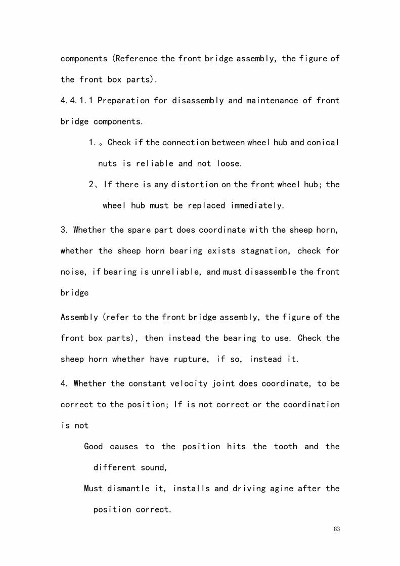
6. Emit the oil in the differential device
7. Pull out the left and right transmission shaft from the
differential device. (Attached Figure 4-4-1)
Attached Figure 4-4-1
1. The right transmission shaft of front bridge
4.4.2.2 Inspection and maintain the front bridge
1、Check whether the dustproof rubber wrap on the left
and right transmission shaft is dilapidation and aging, if so,
instead the new one.
2、Check whether the inner and outer ball cage of the
left and right transmission shaft movement is smooth less. If
it is stagnation and obvious becoming less loosen, replace it.
3、Disassemble the left and right transmission shaft,
cleaning and assemble it again.
86
Attention,
1、The dustproof rubber wrap on the ball cage is not
allowed to contact with the gas and diesel oil.
2、 The dustproof rubber wrap does not allow to be
scratched, a slight scratches can damage the
dustproof rubber wrap very quickly.
3、When reassembles the left and right transmission
shaft, in the ball cage must sufficiently
Enter 2/3 volume with the Lithium lubricating.
4、Open the differential device and inspect the damage
of the gears, axes and gasket, instead those parts
according to the check.
4.4.2.3 Assemble the front bridge parts
1、Put the left and right transmission shaft in the front
bridge differential device. (Attached Figure4-4-1)
2、Pour 0.32L SAE 80 API GL-4 the high quality gear grease
into the front bridge differential device and screws
tight the oil filler bolt
Fastening Torque of Conical Nut, 23N.m
87
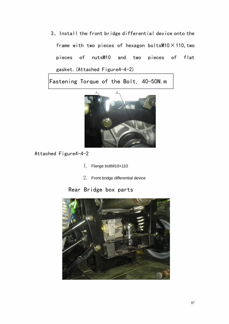
3、Install the front bridge differential device onto the
frame with two pieces of hexagon boltsM10³110,two
pieces of nutsM10 and two pieces of flat
gasket.(Attached Figure4-4-2)
Fastening Torque of the Bolt, 40-50N.m
Attached Figure4-4-2
1. Flange boltM10×110
2. Front bridge differential device
Rear Bridge box parts
88
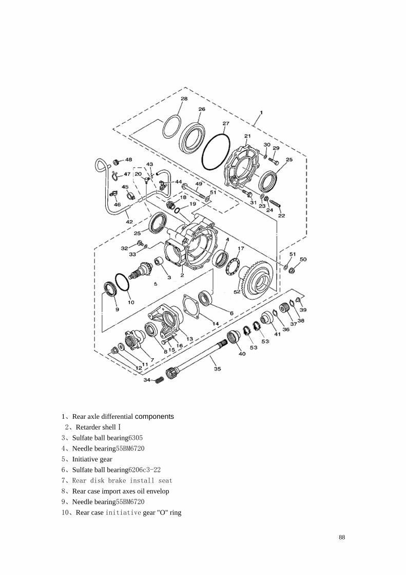
1、Rear axle differential components
2、Retarder shellⅠ
3、Sulfate ball bearing6305
4、Needle bearing55BM6720
5、Initiative gear
6、Sulfate ball bearing6206c3-22
7、Rear disk brake install seat
8、Rear case import axes oil envelop
9、Needle bearing55BM6720
10、Rear case initiative gear "O" ring
89
11、Ⅰrear retarder adjustment gasketⅠ 12、flange nut M12 13、rear disk brake leading
install plate 14、drive piston gasket(0.25T)drive piston gasket(0.30T)drive
piston gasket (0.35T)drive piston gasket(0.40T)drive piston gasket(0.45T)
drive piston gasket(0.50T) 15、bolt M8×20 16、gasketф8.5 17、drive piston gasket
(0.25T)drive piston gasket(0.30T)drive piston gasket(0.35T) gasket with jack
(1.8T) gasket with jack(1.8T) 18、rear case oil filler hole bolt 19、oil filler
hole "O-ring 20、rear retarder pipe 21、retarder shell Ⅱ22、column axes boltM8 23、
gasketф8.5 24、flange nut M825、1rear case export axes oil envelop1 26、sulfate ball bearing
16017c2 27、rear case cover "O-ring 28、circle bearing(0.25T)circle bearing(0.30T)
circle bearing(0.40T)29、boltM8×25 30、gasket ф8.5 31、flange nutM10×22 32、
boltM8×30 33、gasket ф8.5 34、compression spring 35、rear bridge middle transmission
shaft 36、spring flange 37、rear bridge middle
Transmission shaft connecting cover
(The service method of the rear bridge parts is as the same as
the front bridge parts, please refer to the before-mentioned
to operate.)
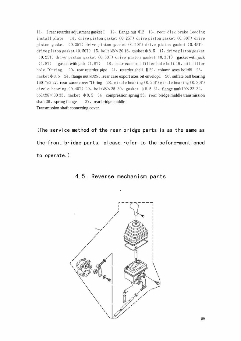
4.5. Reverse mechanism parts
.
90
1. Reverse mechanism operate parts
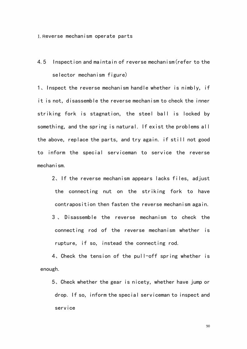
4.5 Inspection and maintain of reverse mechanism(refer to the
selector mechanism figure)
1、Inspect the reverse mechanism handle whether is nimbly, if
it is not, disassemble the reverse mechanism to check the inner
striking fork is stagnation, the steel ball is locked by
something, and the spring is natural. If exist the problems all
the above, replace the parts, and try again. if still not good
to inform the special serviceman to service the reverse
mechanism.
2、If the reverse mechanism appears lacks files, adjust
the connecting nut on the striking fork to have
contraposition then fasten the reverse mechanism again.
3 、 Disassemble the reverse mechanism to check the
connecting rod of the reverse mechanism whether is
rupture, if so, instead the connecting rod.
4、Check the tension of the pull-off spring whether is
enough.
5、Check whether the gear is nicety, whether have jump or
drop. If so, inform the special serviceman to inspect and
service
91
6、To check the few aspect if it is not reveres, ①whether the
clutch is open completely.② whether the shifts gears to
lubricate is reliably (the oil tubing in the reverse mechanism
whether is stopped up).③there is any stagnation in the reverse
mechanism. If so, inform the special serviceman to service.
4.6. Suspension
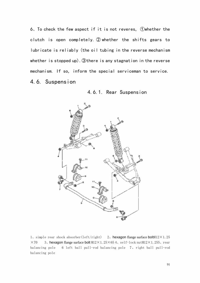
4.6.1. Rear Suspension
1、simple rear shock absorber(left/right) 2、hexagon flange surface boltM12×1.25
×70 3、hexagon flange surface bolt M12×1.25×65 4、self-lock nutM12×1.255、rear
balancing pole 6 left ball pull-rod balancing pole 7、right ball pull-rod
balancing pole
92
8、self-lock nutM8 9、rear balancing pole amortize rubber cover 10、balancing pole
board 11、hexagon flange surface bolM8×16
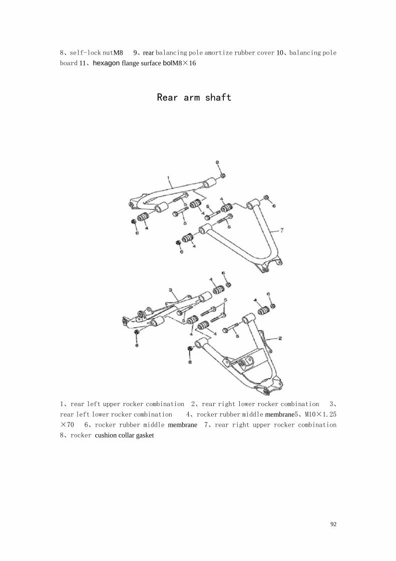
Rear arm shaft
1、rear left upper rocker combination 2、rear right lower rocker combination 3、
rear left lower rocker combination 4、rocker rubber middle membrane5、M10×1.25
×70 6、rocker rubber middle membrane 7、rear right upper rocker combination
8、rocker cushion collar gasket
93
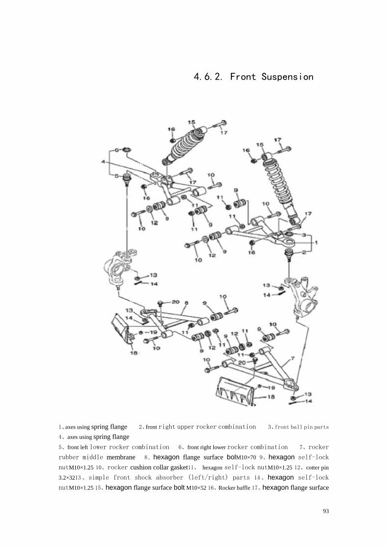
4.6.2. Front Suspension
1、axes using spring flange 2、front right upper rocker combination 3、front ball pin parts
4、axes using spring flange
5、front left lower rocker combination 6、front right lower rocker combination 7、rocker
rubber middle membrane 8、hexagon flange surface bolM10×70 9、hexagon self-lock
nutM10×1.25 10、rocker cushion collar gasket11、 hexagon self-lock nutM10×1.25 12、cotter pin
3.2×3213、simple front shock absorber (left/right) parts 14、hexagon self-lock
nutM10×1.25 15、hexagon flange surface bolt M10×52 16、Rocker baffle 17、hexagon flange surface
94
bolt M618、hexagon flange surface bolt M6×12
4.6.3 Disassembly, Maintenance and Assembly the
supporting rocker parts
1、Disassembly and Maintenance
In the suspension, there is easy to appear the problem with
bushing, cotter pin and shock absorber.
A、If the left and right rocker rocks fiercely, check the few
aspect, either the bushing of the rocker is crushed, the middle
rubber separate or aging and chapped.
B、check whether the cotter pins is credible, if it is not
instead the same spec cotter pin.
C、 The problem with the shock absorber and maintain method,
whether it can returns to the position under the pressure and
the tensional spring is ruptured. If it’s ruptured or nearly
to ruptured, replace the shock absorber. Whether it leak oil,
if so instead the same spec shock absorber. According to the
different request, if there is an oil cup on the rocker must
check it whether complete and refuels.
2、Assembly (See the figure)
1、Use 16pieces of Hexagon Flange BoltM10³70 and 16pieces of
bolt to connect the front upper left and right rocker, front
lower L/R rocker, rear upper L/R rocker and rear lower L/R

95
rocker with the frame. To ensure the fastening torque is
40-45Nm.
2、Connect the front shock absorber, frame and rocker with
4pieces of Hexagon Flange BoltsM10³52 and 4pieces of self-lock
nutsM10.
3、 Connect the rear shock absorber and rear lower rocker
combination with 2pieces of Hexagon Flange BoltsM10³65 and
2pieces of self-lock nutsM10.
4、
Connect the rear shock absorber and frame with 2pieces of
Hexagon Flange BoltsM10³70 and 2pieces of self-lock nutsM10.
Attention:
A、Put on the butter to each part when it is assemble.
B、 Do not scratches the surface of the spare part
surface.
96
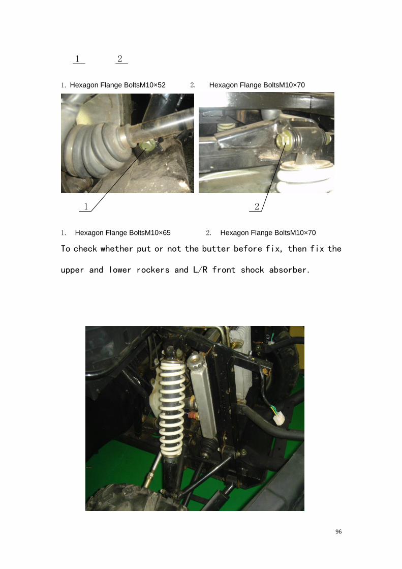
1 2
1. Hexagon Flange BoltsM10×52 2. Hexagon Flange BoltsM10×70
1 2
1. Hexagon Flange BoltsM10×65 2. Hexagon Flange BoltsM10×70
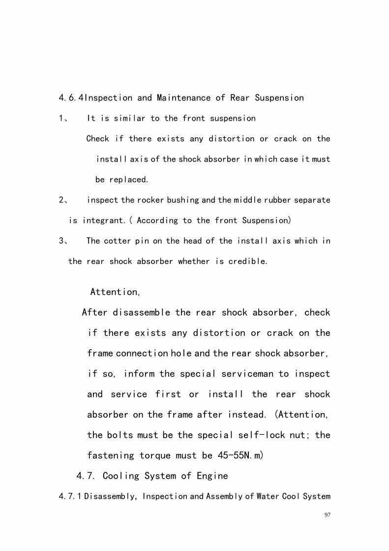
To check whether put or not the butter before fix, then fix the
upper and lower rockers and L/R front shock absorber.
97
4.6.4Inspection and Maintenance of Rear Suspension
1、 It is similar to the front suspension
Check if there exists any distortion or crack on the
install axis of the shock absorber in which case it must
be replaced.
2、 inspect the rocker bushing and the middle rubber separate
is integrant.( According to the front Suspension)
3、 The cotter pin on the head of the install axis which in
the rear shock absorber whether is credible.
Attention,
After disassemble the rear shock absorber, check
if there exists any distortion or crack on the
frame connection hole and the rear shock absorber,
if so, inform the special serviceman to inspect
and service first or install the rear shock
absorber on the frame after instead. (Attention,
the bolts must be the special self-lock nut; the
fastening torque must be 45-55N.m)
4.7. Cooling System of Engine
4.7.1 Disassembly, Inspection and Assembly of Water Cool System
98
4.7.1.1 Disassemble the Water Cool System
4、 1. Disassemble the bumper and front
faceplate(Attached Figure4-5-1)
Attached Figure4-5-1 1. Bumper
2. Front faceplate
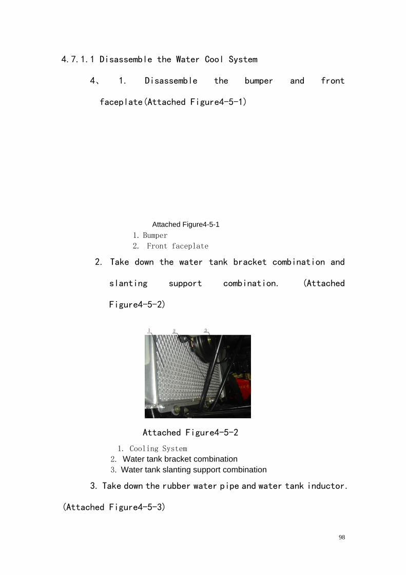
2. Take down the water tank bracket combination and
slanting support combination. (Attached
Figure4-5-2)
Attached Figure4-5-2
1. Cooling System 2. Water tank bracket combination
3. Water tank slanting support combination
3. Take down the rubber water pipe and water tank inductor.
(Attached Figure4-5-3)
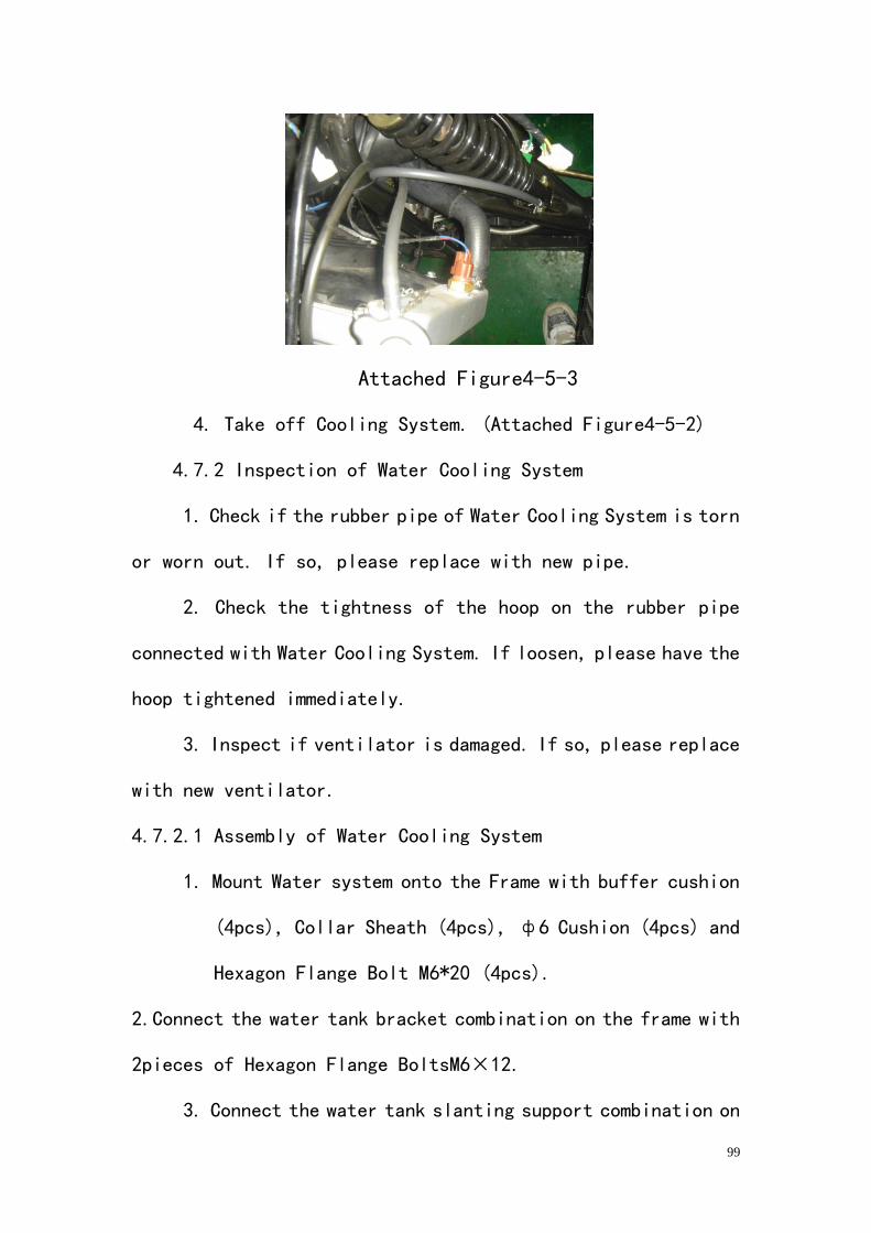
99
Attached Figure4-5-3
4. Take off Cooling System. (Attached Figure4-5-2)
4.7.2 Inspection of Water Cooling System
1. Check if the rubber pipe of Water Cooling System is torn
or worn out. If so, please replace with new pipe.
2. Check the tightness of the hoop on the rubber pipe
connected with Water Cooling System. If loosen, please have the
hoop tightened immediately.
3. Inspect if ventilator is damaged. If so, please replace
with new ventilator.
4.7.2.1 Assembly of Water Cooling System
1. Mount Water system onto the Frame with buffer cushion
(4pcs), Collar Sheath (4pcs), ф6 Cushion (4pcs) and
Hexagon Flange Bolt M6*20 (4pcs).
2.Connect the water tank bracket combination on the frame with
2pieces of Hexagon Flange BoltsM6³12.
3. Connect the water tank slanting support combination on
100
the frame with 2pieces of Hexagon Flange BoltsM6.
4. Use Hoops (4pcs) and Rubber Pipes (2pcs) to connect
Water Cooling System with Engine.
Pour the high quality refrigerating fluid into the water tank
after install.
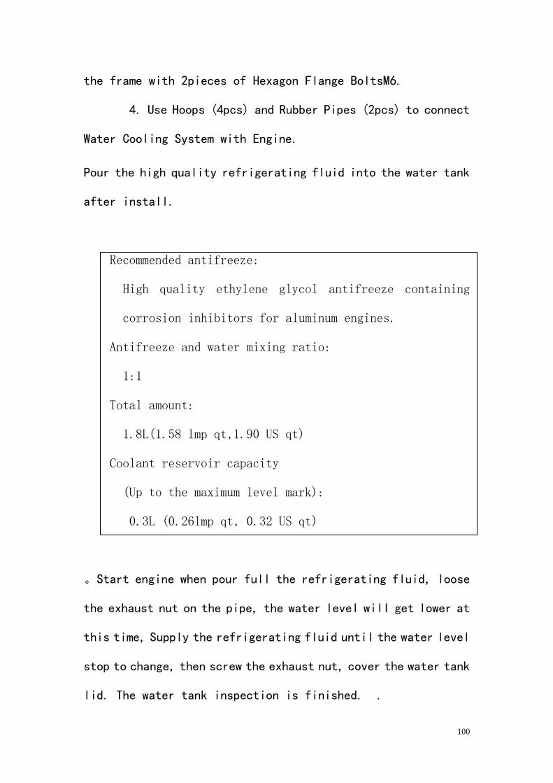
Recommended antifreeze:
High quality ethylene glycol antifreeze containing
corrosion inhibitors for aluminum engines.
Antifreeze and water mixing ratio:
1:1
Total amount:
1.8L(1.58 lmp qt,1.90 US qt)
Coolant reservoir capacity
(Up to the maximum level mark):
0.3L (0.26lmp qt, 0.32 US qt)
。Start engine when pour full the refrigerating fluid, loose
the exhaust nut on the pipe, the water level will get lower at
this time, Supply the refrigerating fluid until the water level
stop to change, then screw the exhaust nut, cover the water tank
lid. The water tank inspection is finished. .
101
4.7.2.2 Oil Cooling System
Except the Cooling System of the engine, this UTV is also
equipped with Oil Cooling System. (Figure)
4.7.2.3Disassembly, Inspection and Assembly of Oil Cooling
System
1、Disassemble the oil cooler
2、Disassemble the connecting steel oil pipe
3、Disassemble the connecting pressure resistance rubber
pipe
4.2.2.4Inspection and maintain the Oil Cooling System
1、Check if the oil cooler is distortion and leak oil. To
adjust the distortion one, and welding the leak one.
If it cannot solve, instead the oil cooler
Check if the steel oil pipe is distortion and leak. To adjust,
intead the serious distortion one and leak oil pipe.
Check if Rubber Pipe is torn, aged, worn out or distorted.
4、Check if the"O"rubber gasket ring which is connect with
the tee oil pipe and the oil cooler is aging and damaged,
instead the aging and damaged one.
102
4.2.2.5Assembly Oil Cooling System
1、To take a pressure resistance inspection to the Oil
Cooling System after maintenance, the pressure is 0.3MPA.a
2、After take the pressure resistance inspection, pass
over 0.03MPA compressed air through the connecting oil cooler,
steel oil pipe and Rubber Pipe for 3 minutes, and do not leak.
3、According to the disassembling order, reverse carries
on the assembly.
4、When it is finished assembly, pour the" L" engine oil,
then start the engine for 10 minutes to check whether
leaks. If it is not, the Oil Cooling System
maintenance is finish.
103
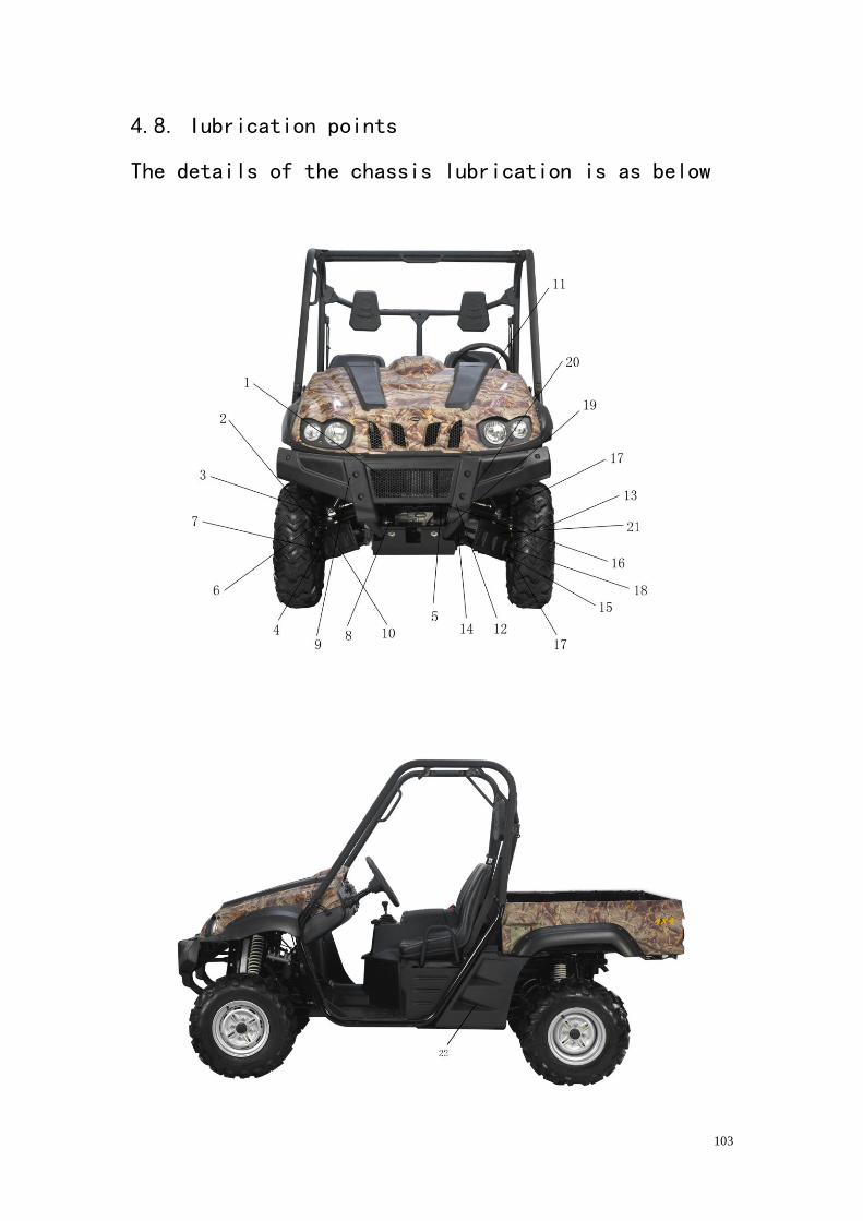
4.8. Iubrication points
The details of the chassis lubrication is as below
104
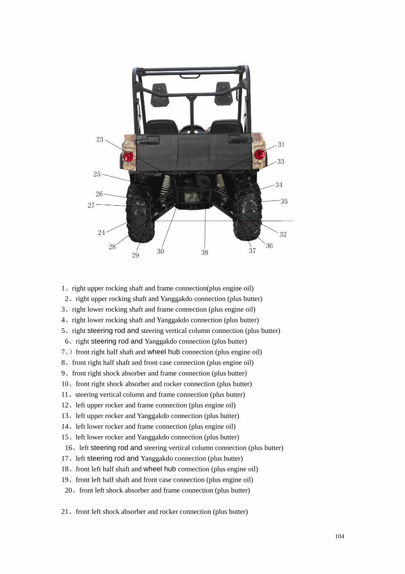
1、right upper rocking shaft and frame connection(plus engine oil)
2、right upper rocking shaft and Yanggakdo connection (plus butter)
3、right lower rocking shaft and frame connection (plus engine oil)
4、right lower rocking shaft and Yanggakdo connection (plus butter)
5、right steering rod and steering vertical column connection (plus butter)
6、right steering rod and Yanggakdo connection (plus butter)
7、)front right half shaft and wheel hub connection (plus engine oil)
8、front right half shaft and front case connection (plus engine oil)
9、front right shock absorber and frame connection (plus butter)
10、front right shock absorber and rocker connection (plus butter)
11、steering vertical column and frame connection (plus butter)
12、left upper rocker and frame connection (plus engine oil)
13、left upper rocker and Yanggakdo connection (plus butter)
14、left lower rocker and frame connection (plus engine oil)
15、left lower rocker and Yanggakdo connection (plus butter)
16、left steering rod and steering vertical column connection (plus butter)
17、left steering rod and Yanggakdo connection (plus butter)
18、front left half shaft and wheel hub connection (plus engine oil)
19、front left half shaft and front case connection (plus engine oil)
20、front left shock absorber and frame connection (plus butter)
21、front left shock absorber and rocker connection (plus butter)
105
22、rear wheel import axis and the case connection (plus engine oil)
23、rear left shock absorber and frame connection (plus butter)
24、rear left shock absorber and rocker connection (plus butter)
25、rear left upper rocker and frame connection(plus engine oil)
26、 rear left lower rocker and frame connection(plus engine oil)
27、rear left upper rocker and Yanggakdo connection(plus butter)
28、rear left lower rocker and Yanggakdo connection (plus butter)
29、rear left half shaft and wheel hub connection (plus engine oil)
30、rear left half shaft and front case connection (plus engine oil)
31、rear right shock absorber and frame connection (plus engine oil)
32、rear right shock absorber and rocker connection (plus butter)
28、33、rear right upper rocker and frame connection(plus engine oil)
34、)rear right lower rocker and frame connection (plus engine oil)
35、rear right upper rocker and Yanggakdo connection (plus butter)
36、rear right lower rocker and Yanggakdo connection (plus butter)
37、rear right half shaft and wheel hub connection (plus engine oil)
38、rear right half shaft and front case connection (plus engine oil)
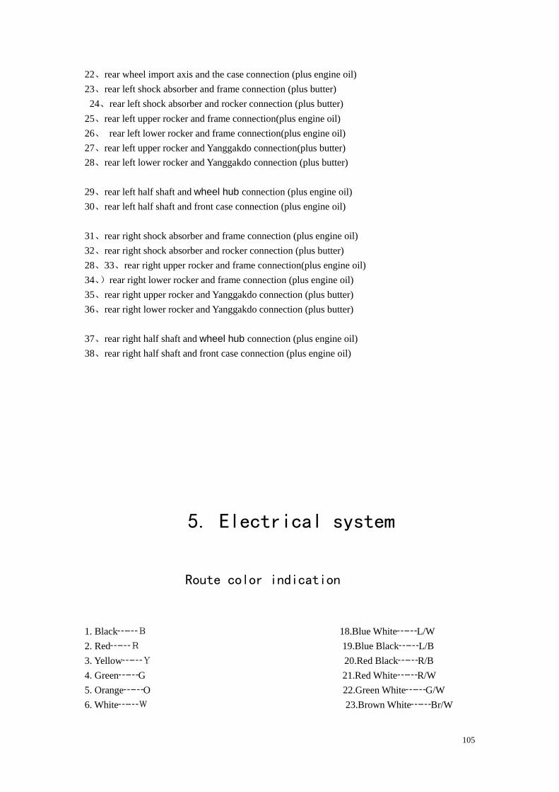
5. Electrical system
Route color indication
1. Black┄┄B 18.Blue White┄┄L/W
2. Red┄┄R 19.Blue Black┄┄L/B
3. Yellow┄┄Y 20.Red Black┄┄R/B
4. Green┄┄G 21.Red White┄┄R/W
5. Orange┄┄O 22.Green White┄┄G/W
6. White┄┄W 23.Brown White┄┄Br/W
106
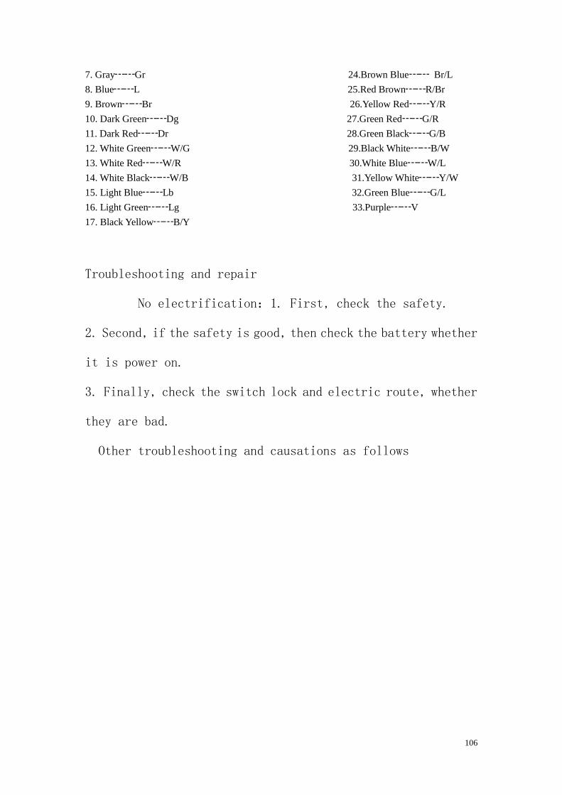
7. Gray┄┄Gr 24.Brown Blue┄┄ Br/L
8. Blue┄┄L 25.Red Brown┄┄R/Br
9. Brown┄┄Br 26.Yellow Red┄┄Y/R
10. Dark Green┄┄Dg 27.Green Red┄┄G/R
11. Dark Red┄┄Dr 28.Green Black┄┄G/B
12. White Green┄┄W/G 29.Black White┄┄B/W
13. White Red┄┄W/R 30.White Blue┄┄W/L
14. White Black┄┄W/B 31.Yellow White┄┄Y/W
15. Light Blue┄┄Lb 32.Green Blue┄┄G/L
16. Light Green┄┄Lg 33.Purple┄┄V
17. Black Yellow┄┄B/Y
Troubleshooting and repair
No electrification:1. First, check the safety.
2. Second, if the safety is good, then check the battery whether
it is power on.
3. Finally, check the switch lock and electric route, whether
they are bad.
Other troubleshooting and causations as follows
107
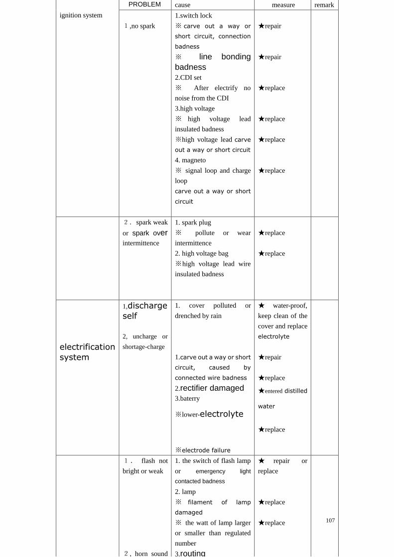
ignition system
cause measure remark
1,no spark
1.switch lock
※ carve out a way or
short circuit, connection
badness
※ line bonding
badness
2.CDI set
※ After electrify no
noise from the CDI
3.high voltage
※ high voltage lead
insulated badness
※high voltage lead carve
out a way or short circuit
4. magneto
※ signal loop and charge
loop
carve out a way or short
circuit
★repair
★repair
★replace
★replace
★replace
★replace
2. spark weak
or spark over
intermittence
1. spark plug
※ pollute or wear
intermittence
2. high voltage bag
※high voltage lead wire
insulated badness
★replace
★replace
electrification
system
1,discharge
self
2, uncharge or
shortage-charge
1. cover polluted or
drenched by rain
1.carve out a way or short
circuit, caused by
connected wire badness
2.rectifier damaged
3.baterry
※lower-electrolyte
※electrode failure
★ water-proof,
keep clean of the
cover and replace
electrolyte
★repair
★replace
★entered distilled
water
★replace
1. flash not
bright or weak
2, horn sound
1. the switch of flash lamp
or emergency light
contacted badness
2. lamp
※ filament of lamp
damaged
※ the watt of lamp larger
or smaller than regulated
number
3.routing
★ repair or
replace
★replace
★replace
PROBLEM
108
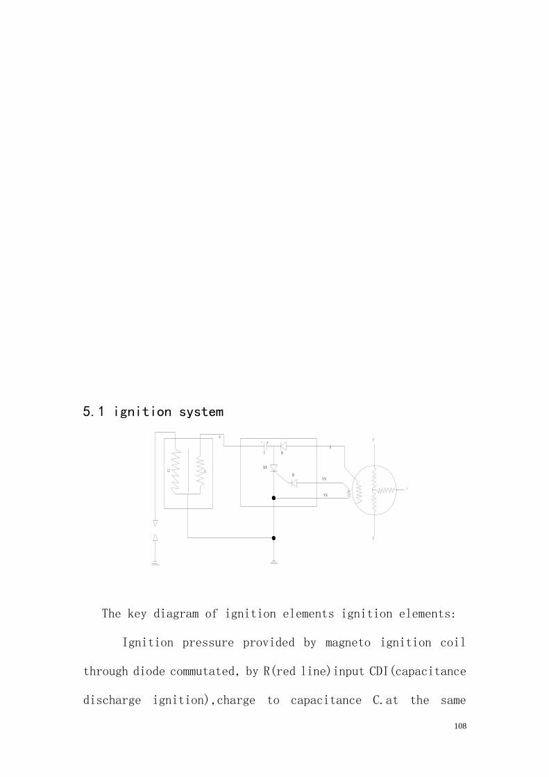
5.1 ignition system
The key diagram of ignition elements ignition elements:
Ignition pressure provided by magneto ignition coil
through diode commutated, by R(red line)input CDI(capacitance
discharge ignition),charge to capacitance C.at the same
109
time ,spring coil produce spring signal ,provided to SCR as the
turn on spring signal ,when reaching the ignition timing, SCR
turn-on capacitance began to discharge at the elementary coil
L1 caused instant lower pressure ,while at the secondary coil
caused induce pressure. Its instant pressure up to 10000V,
sparkover at the clearance of sparkplug (0.6mm).so the engine
ignited
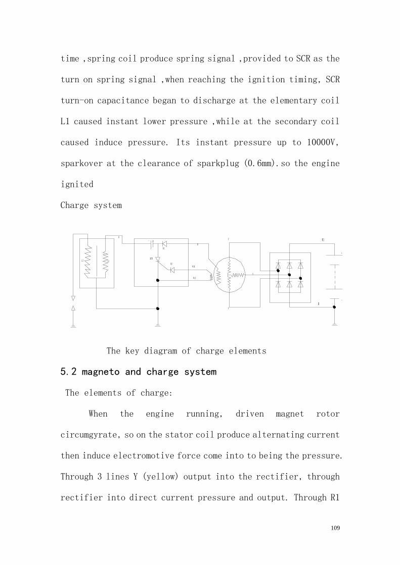
Charge system
The key diagram of charge elements
5.2 magneto and charge system
The elements of charge:
When the engine running, driven magnet rotor
circumgyrate, so on the stator coil produce alternating current
then induce electromotive force come into to being the pressure.
Through 3 lines Y (yellow) output into the rectifier, through
rectifier into direct current pressure and output. Through R1
110
to charge the battery.
5.3 Battery
Under the following problems, please change the battery
1. With long time charge but the pressure do not increase to
a set value.
2. At the bottom of case there is something dirty or
electrode have become white or the case with a sulfate
function
3. Electrode former scratched or scratched by press or
insulation without work.
Pay attention when using
1. Long time out of using but without charge is not correct.
2. Too much charge (so long time charge is not correct,
generally if battery empty, the normal charge time hours)
3. Do not charge under a much higher pressure or electric
current
4. Keep battery at a low temperature and dry place
5. Charge battery before fix it.
If battery without electrolyte, it may cause the
111
rectifier damaged. And the electrolyte is venomous and
dangerous. As it contains vitriol it may cause burn
accident. Battery also contains explode gas, so keep
it far away spark and flame and cigarette. When charge
or using in house, keep the air easy floating. When work
near the battery, please take care of your eyes and keep
kids away from the battery.
If under such accidents, please deal with it as follows or ask
for help from the doctors.
1. Exterior, wash lots of cleaning water
2. Interior, drink milk or water and then milk of magnesia or
egg or rap oil and hospitalize as soon as possible.
3. Eyes wash cleaning water at least 15 minutes and hospitalize
as soon as possible.
5.4: Lighting system
112
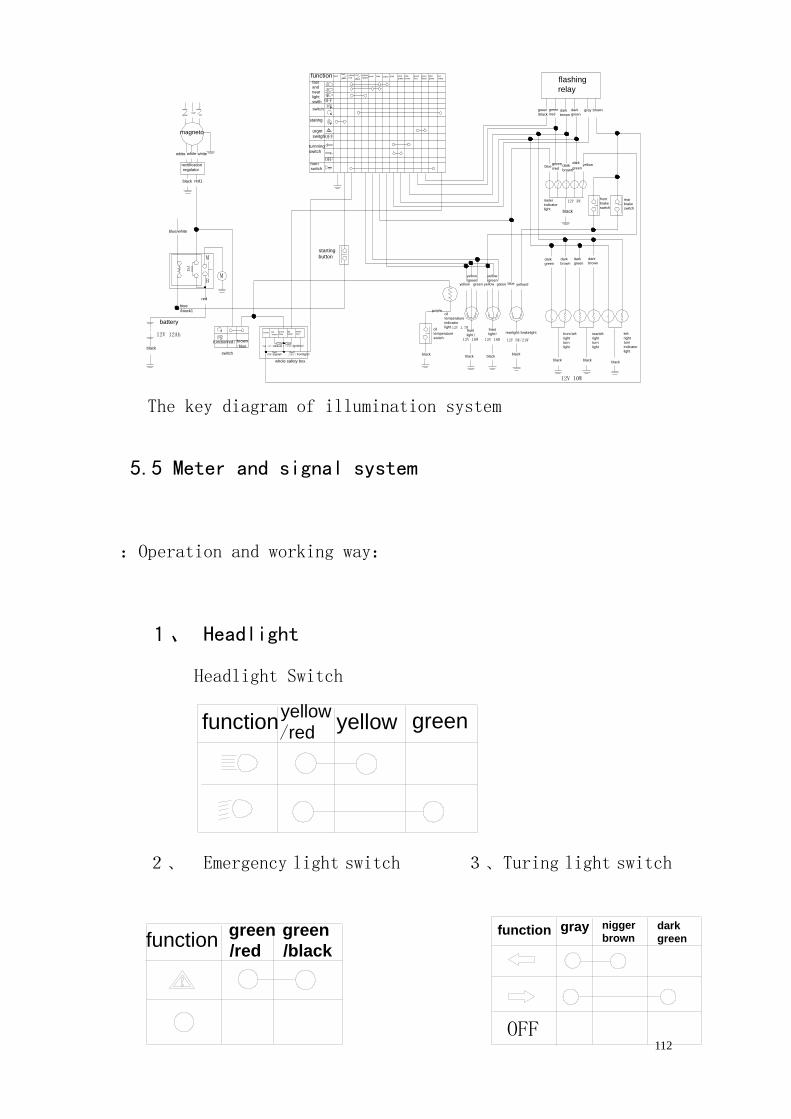
The key diagram of illumination system
5.5 Meter and signal system
:Operation and working way:
1、 Headlight
Headlight Switch
2、 Emergency light switch 3、Turing light switch
greenyellow/red
function yellow
green
/black
green
/redfunction
function
OFF
gray nigger
browndark
green
oil
temperature
indicator
light
left
right
turn
indicator
light
rearleft
right
turn
light
blackblackblack
blackblackblack
green
yellow
/green
functionfast
and
near
light
swith
dark
green
yellow
/redyellow gray
red yellow
/greenblack black
blueblack green blue red
/white
light
green
dark
brown
green
/red
green
/black flashing
relay
battery
12V 12Ah
black
brown
/bluered1function
switch ;10A(signal)
;25A(Ignition);5A(2.4draver)
;25A(frontlight)
biue
/black1
red
red
/whitered
/brown
brown
/blue
yelow
/redbrown
blue/white
M
M
B
15A
black red1
yellow
yellow
/greenblue yellow2greenyellow
12V 18W
black
12V 1.7Woil
temperature
switch
front
light1
purple
front left
right
turn
light
12V 18W 12V 5W/21W
12V 10W
front
light2 rearlight/brakelight
starting
buttondark
green
dark
green
dark
browndark
brown
meter
indicator
lightblack
12V 3W rear
brake
switch
front
brake
switch
stating
switch
magneto
rectification
regulator
white white white
horn
switch
turnning
switch
urgnt
switghOFF
OFF
OFF
green
/redblue dark
brown
dark
greenyellow
green
/redgreen
/blackdark
brown
dark
greengray brownwhite
green
white
redred2
whole safety box
113
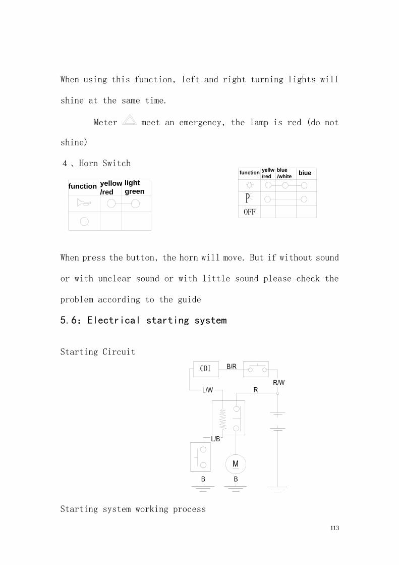
When using this function, left and right turning lights will
shine at the same time.
Meter meet an emergency, the lamp is red (do not
shine)
4、Horn Switch
When press the button, the horn will move. But if without sound
or with unclear sound or with little sound please check the
problem according to the guide
5.6:Electrical starting system
Starting Circuit
Starting system working process
yellow
/red
light
greenfunction
OFF
functionyellw
/red
blue
/whitebiue
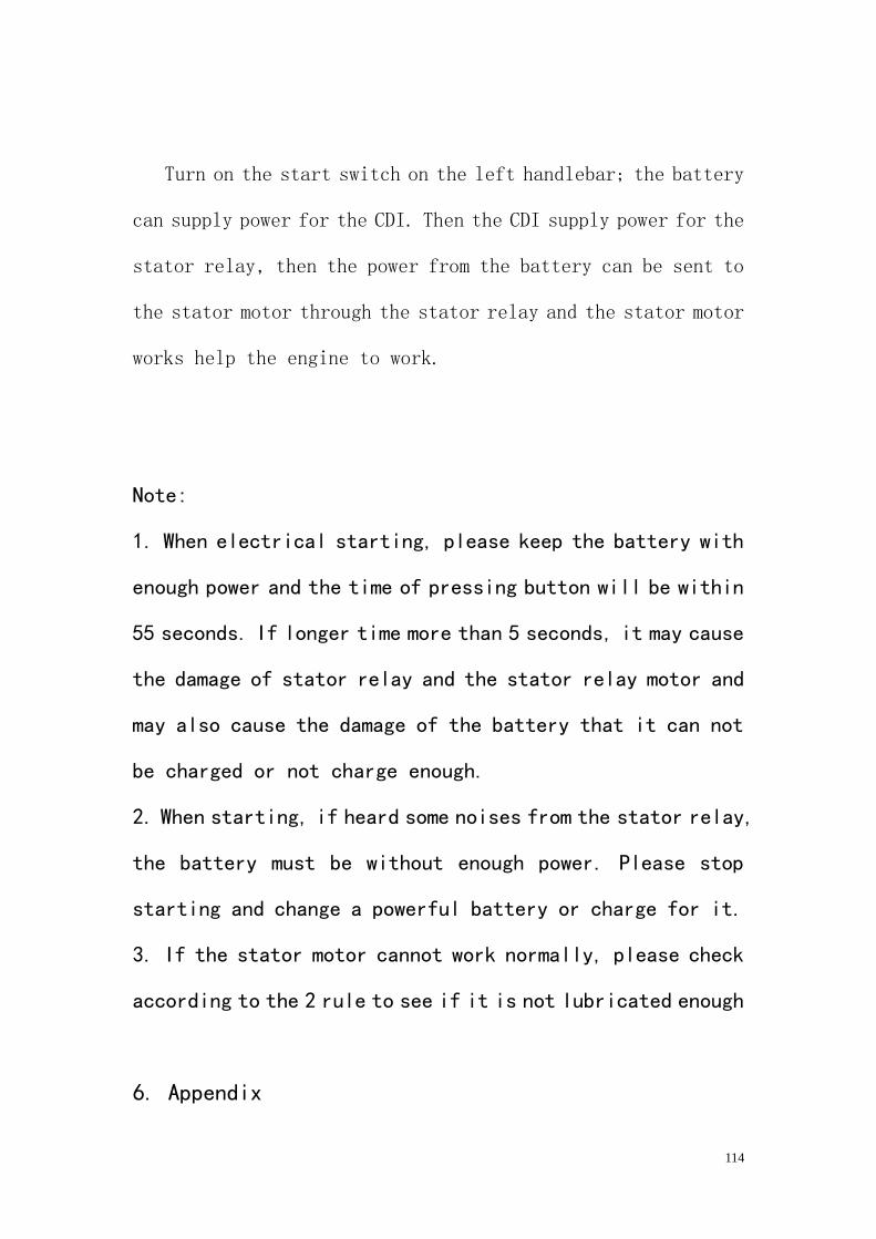
114
Turn on the start switch on the left handlebar; the battery
can supply power for the CDI. Then the CDI supply power for the
stator relay, then the power from the battery can be sent to
the stator motor through the stator relay and the stator motor
works help the engine to work.
Note:
1. When electrical starting, please keep the battery with
enough power and the time of pressing button will be within
55 seconds. If longer time more than 5 seconds, it may cause
the damage of stator relay and the stator relay motor and
may also cause the damage of the battery that it can not
be charged or not charge enough.
2. When starting, if heard some noises from the stator relay,
the battery must be without enough power. Please stop
starting and change a powerful battery or charge for it.
3. If the stator motor cannot work normally, please check
according to the 2 rule to see if it is not lubricated enough
6. Appendix
115
6.1 Specification
6.1.1 Specification of technique
A)Specification of vehicle
Overall length 3010mm
Overall width 1460mm
overall height 1840mm
Wheel base 1890mm
Wheel gauge F1100mm/ R1150mm
Mini. Clearance to the ground 245mm
Seat height 790mm
turning radius 2500mm
Suspension Front:Hydraulic spring swing arm
Rear:Hydraulic spring swing arm
)Braking pattern
(Normal condition)
Front dual disk, Rear single
disk/front and rear linkage, Right
foot/left hand operation
(1):(E-mark)Braking pattern
Primary Brake(1):(E-mark)
Front dual disk, Rear single
disk/front and rear linkage, right
foot/right hand operation
Emergency brake: hand operation
Braking hand operation
(2):Primary Brake(2): Front dual disk, Rear single
disk/front and rear linkage, right
foot/right hand operation
Emergency brake: Engine/ hand operation,Gear shift
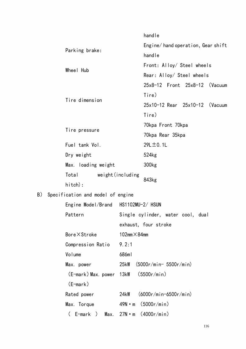
116
handle
Parking brake: Engine/ hand operation,Gear shift
handle
Wheel Hub Front:Alloy/ Steel wheels
Rear:Alloy/ Steel wheels
Tire dimension
25x8-12 Front 25x8-12 (Vacuum
Tire)
25x10-12 Rear 25x10-12 (Vacuum
Tire)
Tire pressure 70kpa Front 70kpa
70kpa Rear 35kpa
Fuel tank Vol. 29L±0.1L
Dry weight 524kg
Max. loading weight 300kg
Total weight(including
hitch): 843kg
B) Specification and model of engine
Engine Model/Brand HS1102MU-2/ HSUN
Pattern Single cylinder, water cool, dual
exhaust, four stroke
Bore³Stroke 102mm³84mm
Compression Ratio 9.2:1
Volume 686ml
Max. power 25kW (5000r/min- 5500r/min)
(E-mark)Max. power
(E-mark)
13kW (5500r/min)
Rated power 24kW (6000r/min-6500r/min)
Max. Torque 49N²m (5000r/min)
( E-mark ) Max. 27N²m (4000r/min)
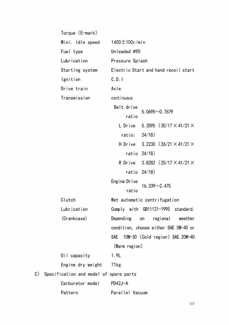
117
Torque(E-mark)
Mini. Idle speed 1400±100r/min
Fuel type Unleaded #90
Lubrication Pressure Splash
Starting system Electric Start and hand recoil start
Ignition C.D.I
Drive train Axle
Transmission continuous
Belt drive
ratio 5.0695~0.7679
L Drive
ratio:
5.3595(30/17³41/21³
24/18)
H Drive
ratio
3.2230(26/21³41/21³
24/18)
R Drive
ratio
3.8282(25/17³41/21³
24/18)
Engine Drive
ratio 16.339~2.475
Clutch Wet automatic centrifugation
Lubrication
(Crankcase)
Comply with GB11121-1995 standard.
Depending on regional weather
condition, choose either SAE 5W-40 or
SAE 10W-30(Cold region)SAE.20W-40
(Warm region)
Oil capacity 1.9L
Engine dry weight 71kg
C) Specification and model of spare parts
Carburetor model PD42J-A
Pattern Parallel Vacuum
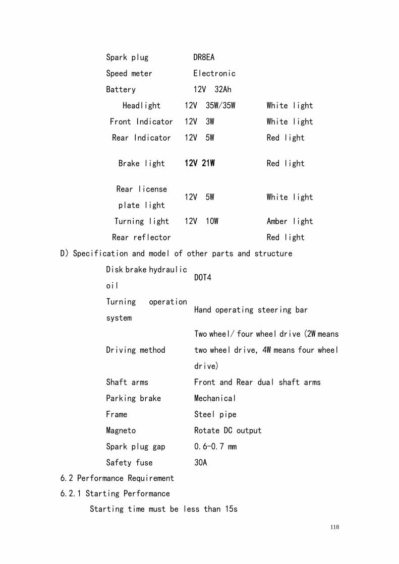
118
Spark plug DR8EA
Speed meter Electronic
Battery 12V 32Ah
Headlight 12V 35W/35W White light
Front Indicator 12V 3W White light
Rear Indicator 12V 5W Red light
Brake light 12V 21W Red light
Rear license
plate light 12V 5W White light
Turning light 12V 10W Amber light
Rear reflector Red light
D)Specification and model of other parts and structure
Disk brake hydraulic
oil DOT4
Turning operation
system Hand operating steering bar
Driving method
Two wheel/ four wheel drive (2W means
two wheel drive, 4W means four wheel
drive)
Shaft arms Front and Rear dual shaft arms
Parking brake Mechanical
Frame Steel pipe
Magneto Rotate DC output
Spark plug gap 0.6-0.7 mm
Safety fuse 30A
6.2 Performance Requirement
6.2.1 Starting Performance
Starting time must be less than 15s
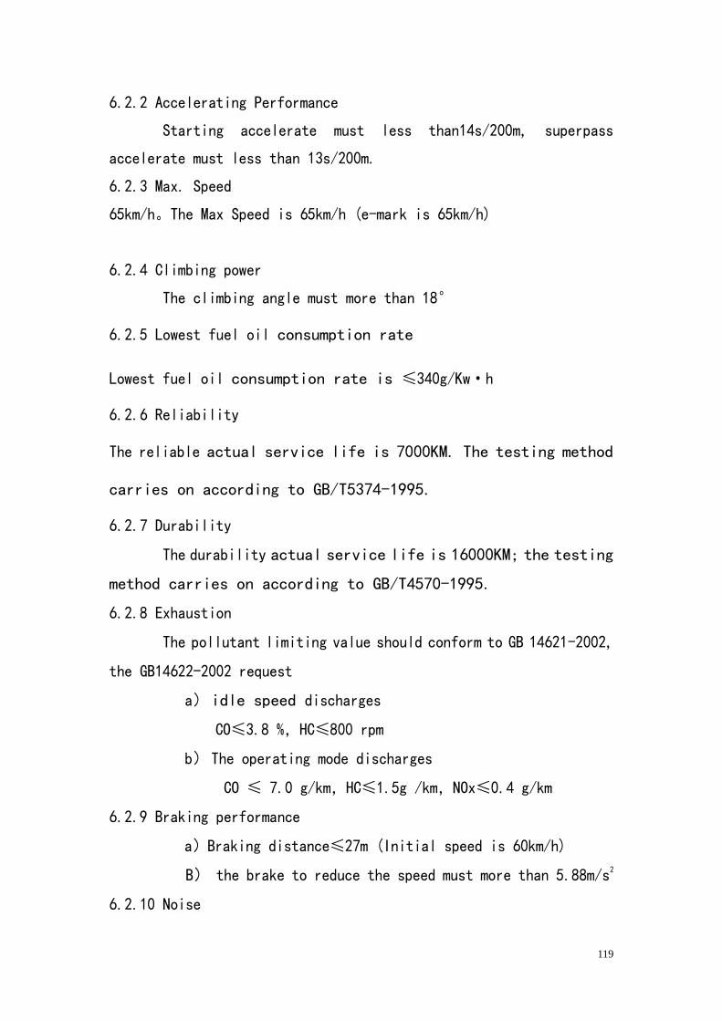
119
6.2.2 Accelerating Performance
Starting accelerate must less than14s/200m, superpass
accelerate must less than 13s/200m.
6.2.3 Max. Speed
65km/h。The Max Speed is 65km/h (e-mark is 65km/h)
6.2.4 Climbing power
The climbing angle must more than 18°
6.2.5 Lowest fuel oil consumption rate
Lowest fuel oil consumption rate is ≤340g/Kw²h
6.2.6 Reliability
The reliable actual service life is 7000KM. The testing method
carries on according to GB/T5374-1995.
6.2.7 Durability
The durability actual service life is 16000KM; the testing
method carries on according to GB/T4570-1995.
6.2.8 Exhaustion
The pollutant limiting value should conform to GB 14621-2002,
the GB14622-2002 request
a) idle speed discharges
CO≤3.8 %,HC≤800 rpm
b) The operating mode discharges
CO ≤ 7.0 g/km,HC≤1.5g /km,NOx≤0.4 g/km
6.2.9 Braking performance
a)Braking distance≤27m (Initial speed is 60km/h)
B) the brake to reduce the speed must more than 5.88m/s2
6.2.10 Noise
120
The acceleration travel noise is not bigger than 79dB (A),
installment noise is 93dB (A), rotate speed is 2750mim2.
6.2.11 Radio harassment characteristic
The multipurpose vehicle produces the radiated interference
permissible value and the ignition system noise remover insertion loss
value, the radio harassment characteristic should conform to
GB14023-2006
6.2.12 parking performance
Multipurpose vehicle when neutral position use parking brake of in
the vehicle arresting gear should guarantee the vehicles in the slope
are 18%, coefficient of adhesion between the tire and the road surface
is not smaller than on 0.7 slope way, the counter- two directions
maintains static fixed is motionless, meantime between many to 5min
6.2.13 the side leans the steady constant angle
The multipurpose vehicle under the idling, the static condition, and
right flank inclines the biggest side to left side to lean the steady
constant angle not to have to be smaller than 25°.
6.2.14 Front illuminator performance
6.2.14.1 The vehicle should be loaded with conforms to GB 5948-1998
or the GB 4599-94 request front illuminator
6.2.14.2 The high beam of each front light luminous
Intensity should achieve 8000cd. When test, its electrical power
System should be at the charge condition
6.2.14.3 The front light beam shines the position to be supposed to
conform to the following stipulation
A)Under the regular service condition, the front light beam shines
the position to be supposed to maintain stably
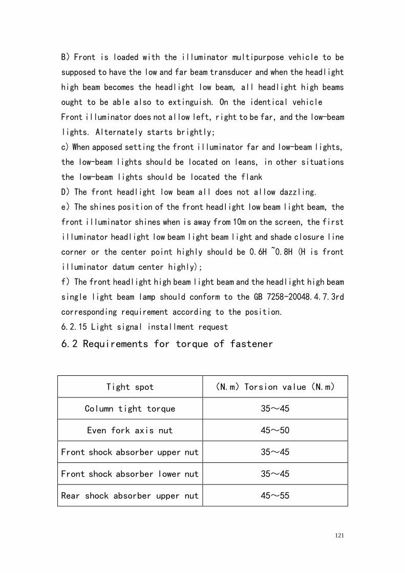
121
B)Front is loaded with the illuminator multipurpose vehicle to be
supposed to have the low and far beam transducer and when the headlight
high beam becomes the headlight low beam, all headlight high beams
ought to be able also to extinguish. On the identical vehicle
Front illuminator does not allow left, right to be far, and the low-beam
lights. Alternately starts brightly;
c) When apposed setting the front illuminator far and low-beam lights,
the low-beam lights should be located on leans, in other situations
the low-beam lights should be located the flank
D)The front headlight low beam all does not allow dazzling.
e)The shines position of the front headlight low beam light beam, the
front illuminator shines when is away from 10m on the screen, the first
illuminator headlight low beam light beam light and shade closure line
corner or the center point highly should be 0.6H ~0.8H (H is front
illuminator datum center highly);
f)The front headlight high beam light beam and the headlight high beam
single light beam lamp should conform to the GB 7258-20048.4.7.3rd
corresponding requirement according to the position.
6.2.15 Light signal installment request
6.2 Requirements for torque of fastener
Tight spot (N.m)Torsion value(N.m)
Column tight torque 35~45
Even fork axis nut 45~50
Front shock absorber upper nut 35~45
Front shock absorber lower nut 35~45
Rear shock absorber upper nut 45~55
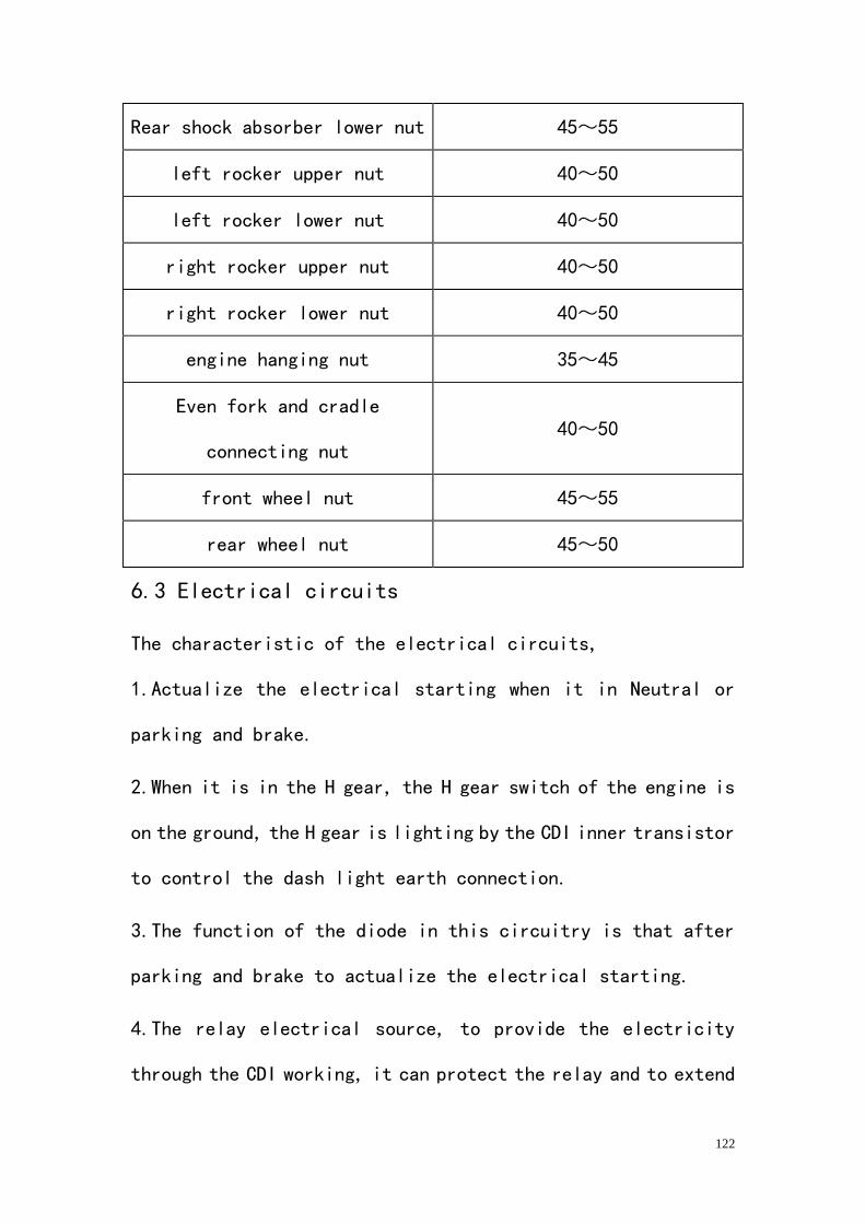
122
Rear shock absorber lower nut 45~55
left rocker upper nut 40~50
left rocker lower nut 40~50
right rocker upper nut 40~50
right rocker lower nut 40~50
engine hanging nut 35~45
Even fork and cradle
connecting nut 40~50
front wheel nut 45~55
rear wheel nut 45~50
6.3 Electrical circuits
The characteristic of the electrical circuits,
1.Actualize the electrical starting when it in Neutral or
parking and brake.
2.When it is in the H gear, the H gear switch of the engine is
on the ground, the H gear is lighting by the CDI inner transistor
to control the dash light earth connection.
3.The function of the diode in this circuitry is that after
parking and brake to actualize the electrical starting.
4.The relay electrical source, to provide the electricity
through the CDI working, it can protect the relay and to extend
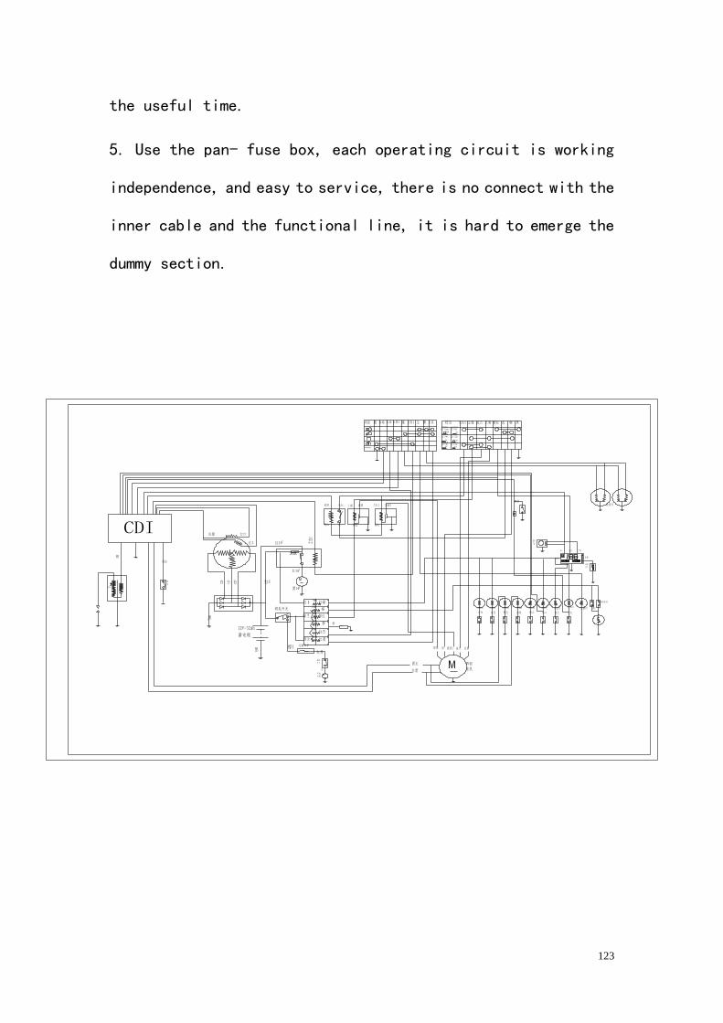
123
the useful time.
5. Use the pan- fuse box, each operating circuit is working
independence, and easy to service, there is no connect with the
inner cable and the functional line, it is hard to emerge the
dummy section.
,
L2 L1
CDI30A
mph
km/h
OVERRIDE

124