Embed Size (px)
Citation preview
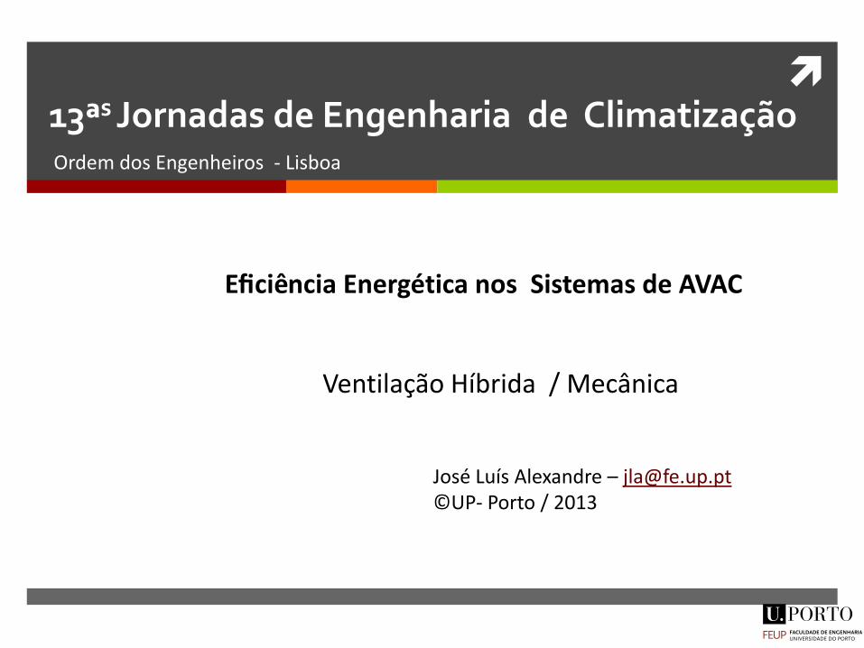
13ªs Jornadas de Engenharia de Climatização Ordem dos Engenheiros - Lisboa
Eficiencia Energetica nos Sistemas de AVAC
Ventilação Híbrida / Mecânica
José Luís Alexandre – [email protected] ©UP- Porto / 2013
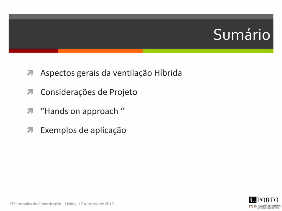
Sumário
Aspectos gerais da ventilação Híbrida
Considerações de Projeto
“Hands on approach “
Exemplos de aplicação
13ª Jornadas da Climatização – Lisboa, 17 outubro de 2013
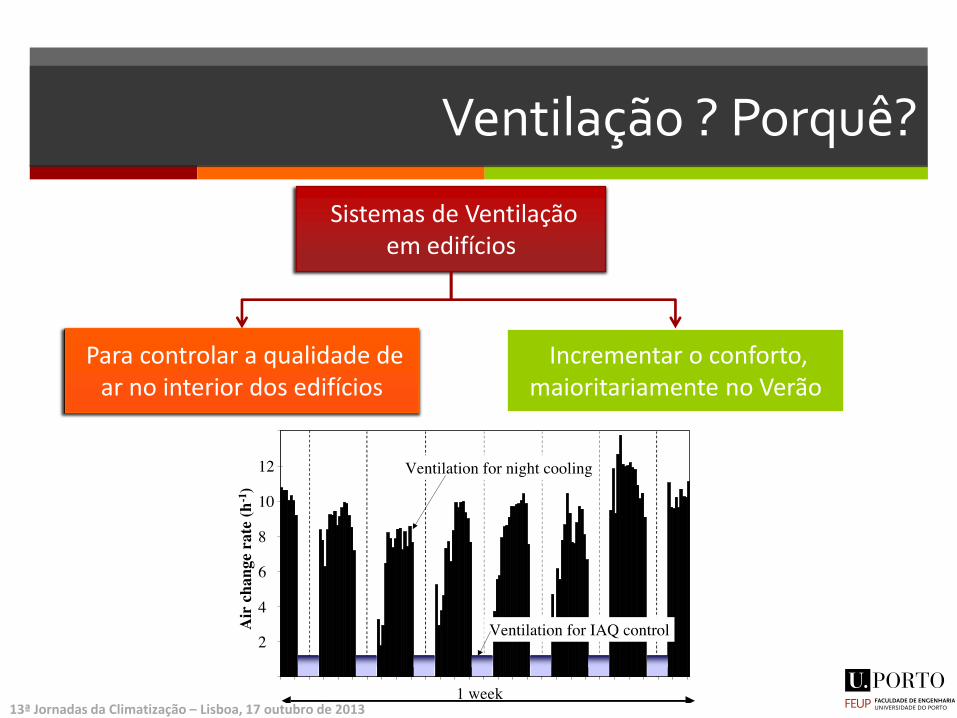
Ventilação ? Porquê?
Sistemas de Ventilação em edifícios
Para controlar a qualidade de ar no interior dos edifícios
Incrementar o conforto, maioritariamente no Verão
13ª Jornadas da Climatização – Lisboa, 17 outubro de 2013
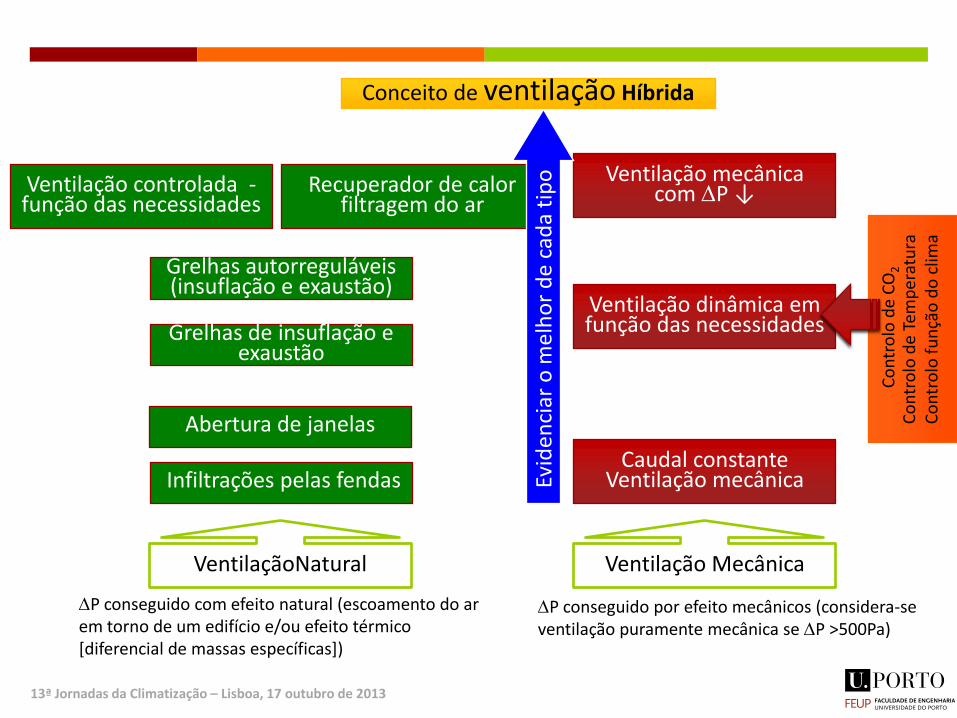
Infiltrações pelas fendas
Abertura de janelas
Grelhas de insuflação e exaustão
Grelhas autorreguláveis (insuflação e exaustão)
Ventilação controlada -função das necessidades
Recuperador de calor filtragem do ar
Ventilação mecânica com DP ↓
Ventilação dinâmica em função das necessidades
Caudal constante Ventilação mecânica E
vid
enci
ar o
mel
ho
r d
e c
ada
tip
o
Conceito de ventilação Híbrida
VentilaçãoNatural Ventilação Mecânica
DP conseguido com efeito natural (escoamento do ar em torno de um edifício e/ou efeito térmico [diferencial de massas específicas])
DP conseguido por efeito mecânicos (considera-se ventilação puramente mecânica se DP >500Pa)
Co
ntr
olo
de
CO
2
Co
ntr
olo
de
Tem
per
atu
ra
Co
ntr
olo
fu
nçã
o d
o c
lima
13ª Jornadas da Climatização – Lisboa, 17 outubro de 2013
Barreiras à ventilação Híbrida
Inércia do Mercado e dos Projetistas
Falta de informação detalha e credível que permita ajudar quem projeta
Ainda há uma lacuna de conhecimento na área da VN/VH de quem projeta sistemas de climatização
Falta de software user-friendlly, confiável e com resultados credíveis
Custo de investimento Alto ? Falta de informação sobre o Cost-effectiveness
Soluções inovadoras são sempre arriscadas (medo da responsabilidade)
Risco do promotor (confiança na solução, medo das queixas dos utilizadores)
Sobre custo para o projetista – inovação quer dizer + trabalho, pago da mesma forma que soluções convencionais
Regulamentação 13ª Jornadas da Climatização – Lisboa, 17 outubro de 2013
Pré Design - Aspetos a evitar Baixo isolamento térmico e pontes térmicas
Infiltrações/exfiltrações (<1 RPH @50Pa)
Poluição interior (evitar materiais não certificados)
Entrada solar descontrolada nos espaços (evitar ganhos excessivos e encandeamento)
Correntes de ar por efeito térmico excessivo
Redução de ventilação dos espaços
Condensações nas superfícies (zonas húmidas sem controlo de ventilação)
Corte total da ventilação durante períodos longos
Acessos limitados aos sistemas de ventilação (grelhas e zonas de admissão de ar)
Edifícios de inércia fraca, principalmente em zonas de fluxos de ar principais
Compartimentos interiores fundos (sem luz natural suficiente)
Recirculação de ar nas proximidades das entradas de ar no edifício
Necessidade de arrefecer quando as condições exteriores são favoráveis ao free-cooling
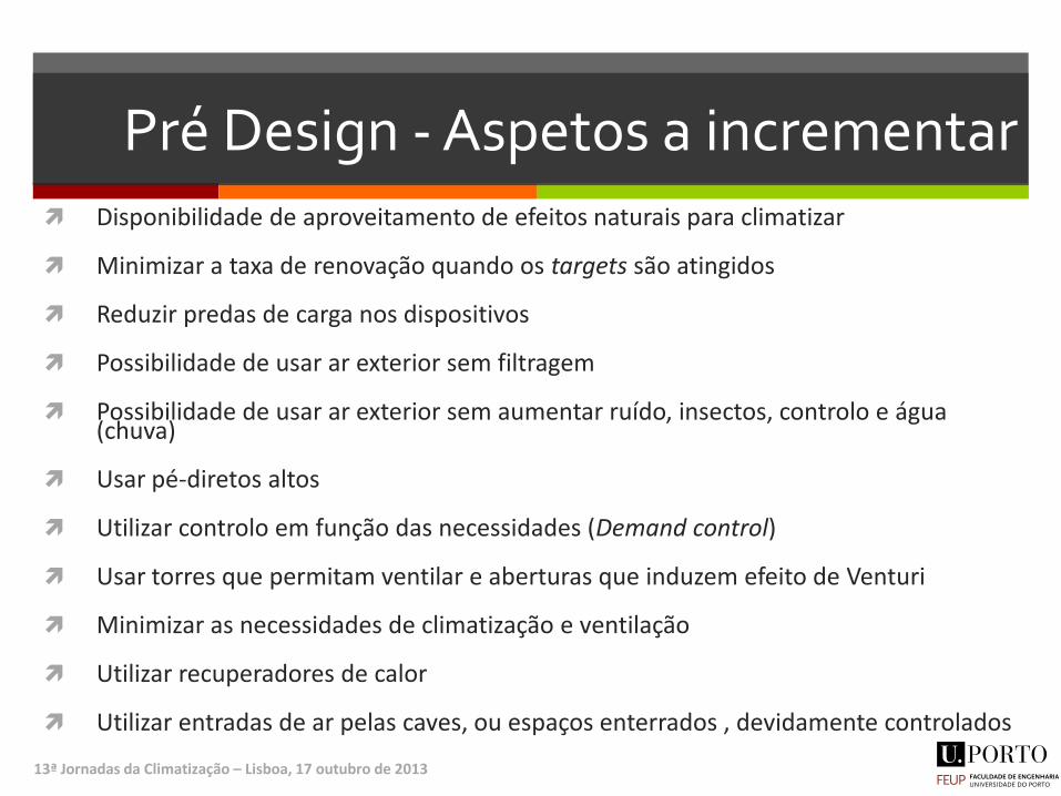
Pré Design - Aspetos a incrementar Disponibilidade de aproveitamento de efeitos naturais para climatizar
Minimizar a taxa de renovação quando os targets são atingidos
Reduzir predas de carga nos dispositivos
Possibilidade de usar ar exterior sem filtragem
Possibilidade de usar ar exterior sem aumentar ruído, insectos, controlo e água (chuva)
Usar pé-diretos altos
Utilizar controlo em função das necessidades (Demand control)
Usar torres que permitam ventilar e aberturas que induzem efeito de Venturi
Minimizar as necessidades de climatização e ventilação
Utilizar recuperadores de calor
Utilizar entradas de ar pelas caves, ou espaços enterrados , devidamente controlados
13ª Jornadas da Climatização – Lisboa, 17 outubro de 2013
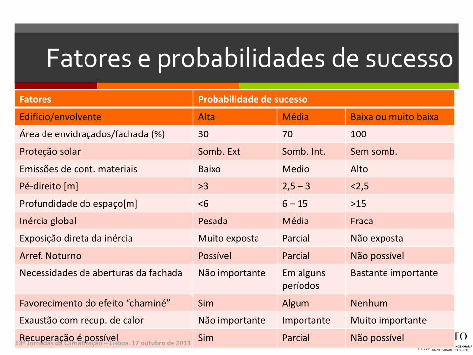
Fatores e probabilidades de sucesso
Fatores Probabilidade de sucesso
Edifício/envolvente Alta Média Baixa ou muito baixa
Área de envidraçados/fachada (%) 30 70 100
Proteção solar Somb. Ext Somb. Int. Sem somb.
Emissões de cont. materiais Baixo Medio Alto
Pé-direito [m] >3 2,5 – 3 <2,5
Profundidade do espaço[m] <6 6 – 15 >15
Inércia global Pesada Média Fraca
Exposição direta da inércia Muito exposta Parcial Não exposta
Arref. Noturno Possível Parcial Não possível
Necessidades de aberturas da fachada Não importante Em alguns períodos
Bastante importante
Favorecimento do efeito “chaminé” Sim Algum Nenhum
Exaustão com recup. de calor Não importante Importante Muito importante
Recuperação é possível Sim Parcial Não possível 13ª Jornadas da Climatização – Lisboa, 17 outubro de 2013

Fatores e probabilidades de de sucesso (II)
Fatores Probabilidade de sucesso
Atuação/atividade/utilização Alta Média Baixa ou muito baixa
Cargas internas (W/m2) <20 20-30 >30
Elevada poluição emitida pela atividade (pintura, impressões, perfumes...)
Espaços separados (divisões + poluentes separadas das restantes)
Zonas parcialmente separada
Zonas sem separações física na zona ocupada
Permanência típica nos espaços de atividade (horas)
8 16 24
Necessidades de ventilação em aquecimento (RPH)
< 2 2 - 4 > 4
13ª Jornadas da Climatização – Lisboa, 17 outubro de 2013
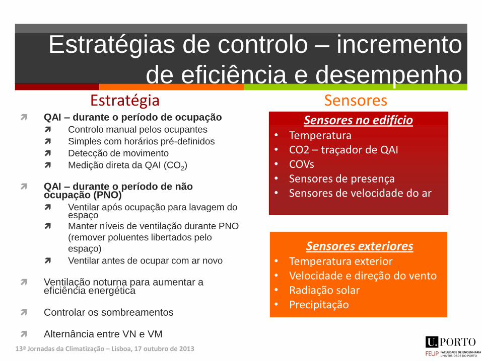
Estratégias de controlo – incremento
de eficiência e desempenho Estratégia
QAI – durante o período de ocupação
Controlo manual pelos ocupantes
Simples com horários pré-definidos
Detecção de movimento
Medição direta da QAI (CO2)
QAI – durante o período de não ocupação (PNO)
Ventilar após ocupação para lavagem do espaço
Manter níveis de ventilação durante PNO
(remover poluentes libertados pelo
espaço)
Ventilar antes de ocupar com ar novo
Ventilação noturna para aumentar a eficiência energética
Controlar os sombreamentos
Alternância entre VN e VM
Sensores Sensores no edifício
• Temperatura • CO2 – traçador de QAI • COVs • Sensores de presença • Sensores de velocidade do ar
Sensores exteriores • Temperatura exterior • Velocidade e direção do vento • Radiação solar • Precipitação
13ª Jornadas da Climatização – Lisboa, 17 outubro de 2013
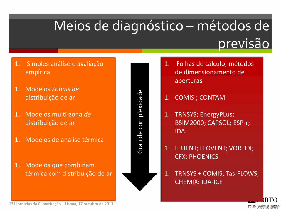
Meios de diagnóstico – métodos de previsão
13ª Jornadas da Climatização – Lisboa, 17 outubro de 2013
1. Simples análise e avaliação empírica
1. Modelos Zonais de
distribuição de ar 1. Modelos multi-zona de
distribuição de ar 1. Modelos de análise térmica
1. Modelos que combinam térmica com distribuição de ar
Gra
u d
e c
om
ple
xid
ade
1. Folhas de cálculo; métodos de dimensionamento de aberturas
1. COMIS ; CONTAM
1. TRNSYS; EnergyPLus;
BSIM2000; CAPSOL; ESP-r; IDA
1. FLUENT; FLOVENT; VORTEX;
CFX: PHOENICS
1. TRNSYS + COMIS; Tas-FLOWS; CHEMIX: IDA-ICE

13ª Jornadas da Climatização – Lisboa, 17 outubro de 2013
EXEMPLOS DE APLICAÇÃO

Estratégia de funcionamento típico de um edifício (ao nível da ventilação)
13ª Jornadas da Climatização – Lisboa, 17 outubro de 2013
Ventilação para garantir QAI V. Natural V. Mecânica
Ven
tila
ção
par
a C
on
fort
o T
érm
ico
A
rref
ecim
ento
mec
. V.
Nat
ura
l
❷
❹
❶
❶ ❹
③
①
②
④
④
Condições climáticas
Condições climáticas
Condições climáticas
Co
nd
içõ
es c
limát
icas
➀ - Edifício em funcionamento normal
➊ - Edifício em funcionamento temporário
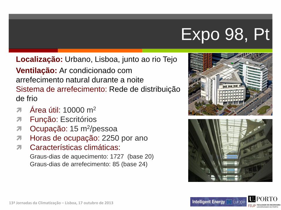
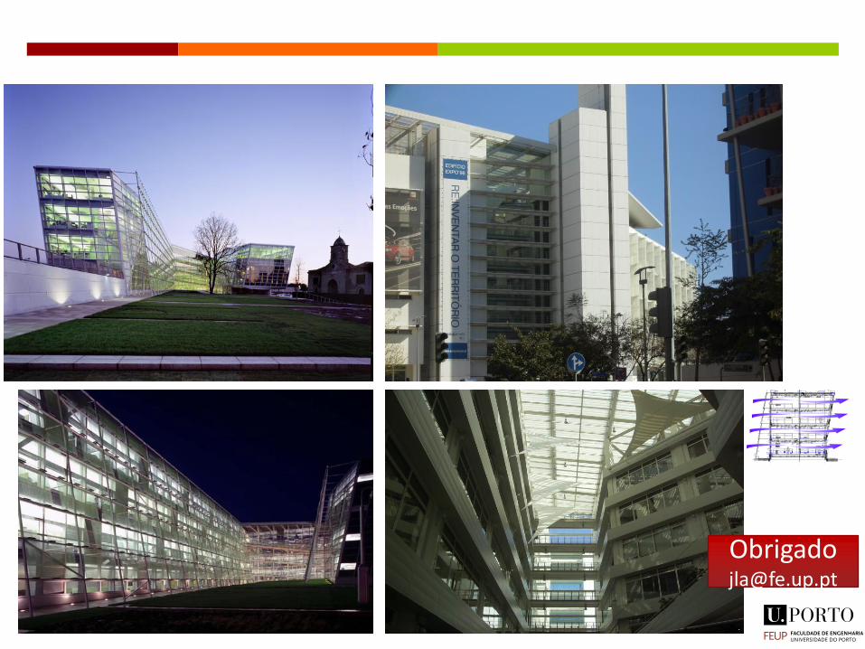
Expo 98, Pt
13ª Jornadas da Climatização – Lisboa, 17 outubro de 2013
Localização: Urbano, Lisboa, junto ao rio Tejo
Ventilação: Ar condicionado com
arrefecimento natural durante a noite
Sistema de arrefecimento: Rede de distribuição
de frio
Área útil: 10000 m2
Função: Escritórios
Ocupação: 15 m2/pessoa
Horas de ocupação: 2250 por ano
Características climáticas: Graus-dias de aquecimento: 1727 (base 20)
Graus-dias de arrefecimento: 85 (base 24)

Expo 98 (II)
13ª Jornadas da Climatização – Lisboa, 17 outubro de 2013
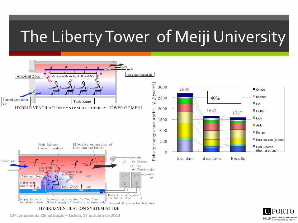
Consumo anual
As poupanças rondam os 15%* relativamente a um edifício de serviços convencional * Apenas nas áreas avaliadas pelo projeto BuildAdvent
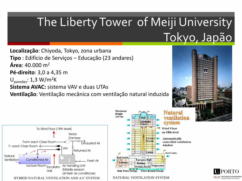
The Liberty Tower of Meiji University Tokyo, Japão
13ª Jornadas da Climatização – Lisboa, 17 outubro de 2013
IEA ECBCS Annex 35 : HybVent
1 of 25
Pilot study report :
The Liberty Tower of Meiji University Tokyo, Japan
1 GENERAL INFORMATION 1.1.1 Report date
February 2002
1.1.2 Principal researchers
Shinsuke Kato
4-6-1 Komaba, Meguro, Tokyo 153-8505, Japan
Tel: +81-3-5452-6431
Fax: +81-3-5452-6432
e-Mail: [email protected]
Tomoyuki Chikamoto
2-1-3 Koraku, Bunkyo, Tokyo 112-8565, Japan
Tel: +81-3-3813-3361
Fax: +81-3817-7072
e-Mail: [email protected]
Localização: Chiyoda, Tokyo, zona urbana Tipo : Edifício de Serviços – Educação (23 andares) Área: 40.000 m2 Pé-direito: 3,0 a 4,35 m Uparedes: 1,3 W/m2K Sistema AVAC: sistema VAV e duas UTAs Ventilação: Ventilação mecânica com ventilação natural induzida
Pilot study report : The Liberty Tower of Meiji University
12 of 25
On 18th floor, there are openings to exhaust the air, which passes through 4 wind paths designed
toward 4 different directions, and is led to outside the building. The airflow of the wind floor on
18th level was simulated by CFD, and found that the outdoor air flows on the wind floor at a
speed without declining. Therefor the wind floor creates driving force for ventilation that
stimulates air intake via perimeter counter units and exhaust through the opening at the top of
wind core. As the wind floor open to 4 directions, the driving force is expected to be stable
through the year with regardless of wind direction.
It adapts natural ventilation with air-conditioning system, then occupant zone air climate are kept
comfortably by passive natural ventilation power and active minimum air-conditioning power.
3.6.2 Components
NATURAL VENTILATION SYSTEM WIND FLOOR ON 18TH LEVEL
TYPICAL FLOOR PLAN WIND FLOOR PLAN
Lecture Rooms
Escalator
Refresh SpaceWC WC
M/RM/R
Wind is exhausted at the top of EscalatorWind is exhausted at the top of Escalator
(Wind floor on 18th level)(Wind floor on 18th level)
Wind fence
Exhaust opening on the top of escalator void
Wind pass through
on this floor
Wind fence
Exhausted air from
Escalator hole
The Liberty Tower of Meiji University
13ª Jornadas da Climatização – Lisboa, 17 outubro de 2013
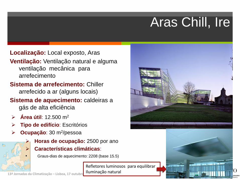
Aras Chill, Ire
13ª Jornadas da Climatização – Lisboa, 17 outubro de 2013
Localização: Local exposto, Aras
Ventilação: Ventilação natural e alguma
ventilação mecânica para
arrefecimento
Sistema de arrefecimento: Chiller
arrefecido a ar (alguns locais)
Sistema de aquecimento: caldeiras a
gás de alta eficiência
Área útil: 12.500 m2
Tipo de edifício: Escritórios
Ocupação: 30 m2/pessoa Horas de ocupação: 2500 por ano
Características climáticas:
• Graus-dias de aquecimento: 2208 (base 15.5)
Refletores luminosos para equilibrar Iluminação natural
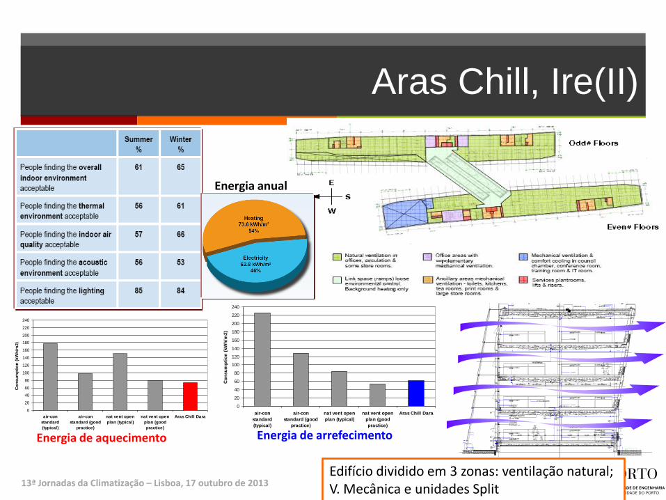
Aras Chill, Ire(II)
sdsada
13ª Jornadas da Climatização – Lisboa, 17 outubro de 2013 Edifício dividido em 3 zonas: ventilação natural; V. Mecânica e unidades Split
0
20
40
60
80
100
120
140
160
180
200
220
240
air-con
standard
(typical)
air-con
standard (good
practice)
nat vent open
plan (typical)
nat vent open
plan (good
practice)
Aras Chill Dara
Co
nsu
mp
tio
n (
kW
h/m
2)
0
20
40
60
80
100
120
140
160
180
200
220
240
air-con
standard
(typical)
air-con
standard (good
practice)
nat vent open
plan (typical)
nat vent open
plan (good
practice)
Aras Chill Dara
Co
nsu
mp
tio
n (
kW
h/m
2)
Energia de aquecimento Energia de arrefecimento
Energia anual
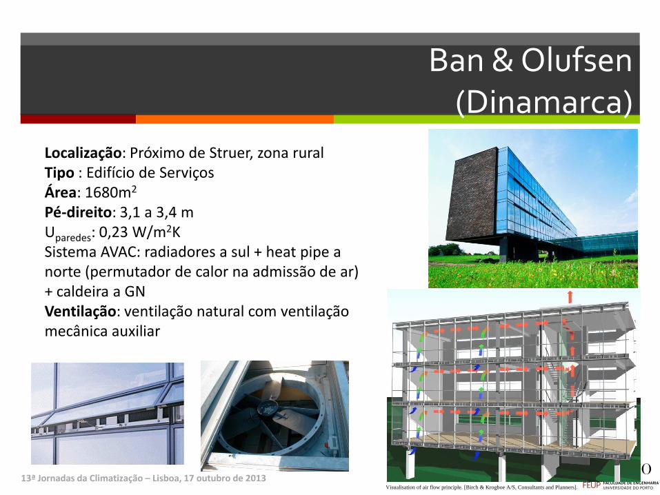
Ban & Olufsen (Dinamarca)
This technical paper is not an official IEA-ECB&CS Annex 35 publication. The views andjudgements expressed are those of the authors and do not necessarily reflect those of Annex35 or IEA-ECB&CS.
INTERNATIONAL ENERGY AGENCY
ENERGY CONSERVATION IN BUILDINGS AND COMMUNITY SYSTEMS
Pilot study report :
Bang & Olufsen Head QuarterStruer, Denmark
O. J. Hendriksen, Esbensen Consulting Engineers, [email protected]
H. Brohus, Aalborg University, [email protected]
C. Frier, Aalborg University, [email protected]
P. Heiselberg, Aalborg University, [email protected]
I EA
13ª Jornadas da Climatização – Lisboa, 17 outubro de 2013
IEA ECBCS Annex 35 : HybVent
9 of 18
Visualisation of air flow principle. [Birch & Krogboe A/S, Consultants and Planners].
3.4.2 Components
3.4.2.1 Fresh air inlets
Inlet windows are located in the horizontal division of each floor.
Narrow windows at the north facade are operated
automatically by the BEMS system.
Detail of automatic window with ribbed heat pipe. [KHR
Architects]
Localização: Próximo de Struer, zona rural Tipo : Edifício de Serviços Área: 1680m2 Pé-direito: 3,1 a 3,4 m Uparedes: 0,23 W/m2K Sistema AVAC: radiadores a sul + heat pipe a norte (permutador de calor na admissão de ar) + caldeira a GN Ventilação: ventilação natural com ventilação mecânica auxiliar
IEA ECBCS Annex 35 : HybVent
9 of 18
Visualisation of air flow principle. [Birch & Krogboe A/S, Consultants and Planners].
3.4.2 Components
3.4.2.1 Fresh air inlets
Inlet windows are located in the horizontal division of each floor.
Narrow windows at the north facade are operated
automatically by the BEMS system.
Detail of automatic window with ribbed heat pipe. [KHR
Architects]
Pilot study report : Bang & Olufsen Head Quarter
10 of 18
3.4.2.2 Fans
Two axial fans with a diameter of 1000 mm in each cowl. Three blade propeller types with a pitch
angle of 15º. Design air flow rate of 1 m3/s for each fan. The fans are frequency controlled from 0-
900 rpm.
View from top of the roof with extract cowl. View from the inside of the cowl with one of the two axial fans.
3.4.2.3 Room supply & extract devices
Inlet grilles located in floor and extract via open connections to two stairwells. See previous
photos.
Room supply in the horizontal division with inlet grilles. Details of air inlet with removed grille showing the ribbed
heat pipes.
3.4.2.4 Air exhaust outlets
Extract via top of stairwells connected to a special designed roof cowl for improvement of wind
driving forces. See previous photos.
Ban & Olufsen (II)
13ª Jornadas da Climatização – Lisboa, 17 outubro de 2013
Pilot study report : Bang & Olufsen Head Quarter
12 of 18
3.8.2 Plant
The costs of the hybrid ventilation system with mechanical and electrotechnical installations,
excluding BEMS, were 77 Euro/m2. The typical costs of mechanical ventilation for a building of
similar size and with 3 ach. will be approximately 147 Euro/m2 including BEMS.
3.8.3 Control system
The costs of the part of the BEMS control system serving the hybrid ventilation system at Bang &
Olufsen were 42 Euro/m2.
3.9 Monitoring programme
See file: ParList DK BOHQ.pdf
3.10 Results from monitoring programme
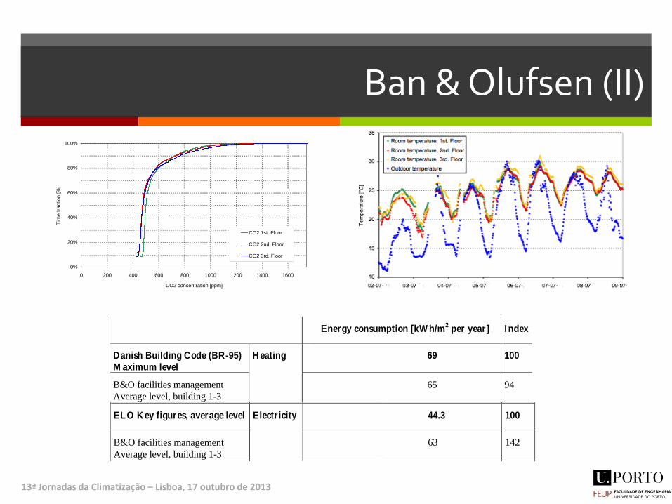
The overall results from one year of monitoring by the BEMS system is shown in the following figures and
tables. The monitoring was performed from 01.09.2000 – 31.08.2001 with logging intervals of 15 minutes.
The hybrid ventilation system is demand controlled either by CO2 level during the winter period and by
room temperature during the summer period. During the whole monitoring period the hybrid ventilation
system were controlled by a CO2 set point of 1000 ppm with a deadband of +/-75 ppm. The set point of the
control system in case of too high room temperature were 25°C.
During monitoring approximately 10% of data were lost due to problems with data logging in the BEMS
system. Most of the lost data were in the period from 09.10.2000 to 31.10.2000 corresponding to about 6%
of the monitoring period.
0%
20%
40%
60%
80%
100%
0 200 400 600 800 1000 1200 1400 1600
CO2 concentration [ppm]
Tim
e f
raction [
%]
CO2 1st. Floor
CO2 2nd. Floor
CO2 3rd. Floor
Cumulated frequency distribution curves of CO2 concentration at each of the three office floors.
Pilot study report : Bang & Olufsen Head Quarter
16 of 18
Percentage of monitoring period (8760 hours)
Hybrid ventilation potentially overruled due to
low outdoor temperatures (<5°C)
Adjusted during monitoring period
25%
Hybrid ventilation potentially overruled due to
strong wind (>11 m/s)
Adjusted during monitoring period
1%
Hybrid ventilation running in night cooling mode 4%
Control constraints of the hybrid ventilation system and period of night cooling mode
Hours with temperatures above
26°C during the working period
Hours with temperatures above
27°C during the working period
DS 474 100 25
1st Floor 90 26
2nd
Floor 88 27
3rd
Floor 226 100
Outdoor air 17 14
Outdoor air according to Danish
Design Reference Year (CPH.DRY)
21 13
Monitored room temperatures compared to the adopted design criteria according to Danish Standard DS-
474. The hours are counted for a working period from 8 a.m. to 5 p.m. at Monday to Friday.
The adopted design criteria from DS–474 is fulfilled for both first and second floor, but at the third floor
the accepted hours with overheating is exceeded. The inlet openings at each of the three floors have similar
free areas, so this is an indication of a too low neutral plane, leading to transfer of air from the lower floors
to the upper floor. Another indication is the CO2 concentration, which is also remarkably higher at the third
floor compared to the to lower floors.
Energy consumption [kW h/m2 per year] I ndex
Danish Building Code (BR-95)
M aximum level
69 100
B&O facilities management
Average level, building 1-3
65 94
Annex 35 monitoring, building 1
Adjusted to normal year
H eating
Ribbed heat pipes
Radiators
15
83 98 142
ELO K ey figures, average level 44.3 100
B&O facilities management
Average level, building 1-3
63 142
Annex 35 monitoring, building 1
Electr icity
Assisting fans
Lighting and
appliances
1.7
64 66 149
Pilot study report : Bang & Olufsen Head Quarter
16 of 18
Percentage of monitoring period (8760 hours)
Hybrid ventilation potentially overruled due to
low outdoor temperatures (<5°C)
Adjusted during monitoring period
25%
Hybrid ventilation potentially overruled due to
strong wind (>11 m/s)
Adjusted during monitoring period
1%
Hybrid ventilation running in night cooling mode 4%
Control constraints of the hybrid ventilation system and period of night cooling mode
Hours with temperatures above
26°C during the working period
Hours with temperatures above
27°C during the working period
DS 474 100 25
1st Floor 90 26
2nd
Floor 88 27
3rd
Floor 226 100
Outdoor air 17 14
Outdoor air according to Danish
Design Reference Year (CPH.DRY)
21 13
Monitored room temperatures compared to the adopted design criteria according to Danish Standard DS-
474. The hours are counted for a working period from 8 a.m. to 5 p.m. at Monday to Friday.
The adopted design criteria from DS–474 is fulfilled for both first and second floor, but at the third floor
the accepted hours with overheating is exceeded. The inlet openings at each of the three floors have similar
free areas, so this is an indication of a too low neutral plane, leading to transfer of air from the lower floors
to the upper floor. Another indication is the CO2 concentration, which is also remarkably higher at the third
floor compared to the to lower floors.
Energy consumption [kW h/m2 per year] I ndex
Danish Building Code (BR-95)M aximum level
69 100
B&O facilities management
Average level, building 1-3
65 94
Annex 35 monitoring, building 1
Adjusted to normal year
Heating
Ribbed heat pipes
Radiators
15
83 98 142
ELO Key figures, average level 44.3 100
B&O facilities management
Average level, building 1-3
63 142
Annex 35 monitoring, building 1
Electricity
Assisting fans
Lighting and
appliances
1.7
64 66 149
Obrigado [email protected]