Embed Size (px)
Citation preview

Scales Lecture Notes: Spring 2017 S17_Scales_Handouts_Answersblankedout.docx Handout Pg 1 of 8
1
SCALES
Done as Ratios or Equivalent Units Reading a Scaled Drawing Creating a Scaled Drawing
Scale as a RATIO
Often the scale of the drawing is just specified as a ratio of the size
of the Drawing Units to the of the Object’s actual length or D:O Alternate terminology is Paper:Real or Print:Real Consider it as a fraction…. helps you visualize if the drawing is
going to be larger or smaller than the actual object. Is D/O larger than 1? Then drawing on paper is larger than object’s real size. If D/O is smaller than 1, then the drawing on the paper is smaller than the object’s real size.
See Fig 11 page 31
SCALE 1:1FULL SIZE
SCALE 1:2
1/2 Also known as HALF SIZE
2
SCALE 2:1
2/1 Also known as
DOUBLE SIZE
REAL
REAL

Scales Lecture Notes: Spring 2017 S17_Scales_Handouts_Answersblankedout.docx Handout Pg 2 of 8
Difference between MECHANICAL and ARCHITECTURAL
3
Watch for the SIZE label and the number of divisions. SIZE refers to MECHANICAL: “n” inch = 1 INCH Where “n” can be 1/4, 3/8, 1/2, or 3/4 of an inch Divisions of 2, 4, 8, 16, 32 for fraction of an inch measurement
1/4 INCH = 1 INCH
G
G is 6 5/8 inches
In this case “n” is ¼, there is a Size label so it is Mechanical There are 8 divisions, so each division is represents 1/8 inch
in real space.
Inches on both sides of equation!
See Fig. 17 on pg. 35
MECHANICAL
Difference between MECHANICAL and ARCHITECTURAL
4
No “SIZE” label refers to Architectural: “n” inch = 1 FOOT 12 divisions (or 6, 24, or 48) on end for
inch and fraction of an inch measurements
1/4 INCH = 1 FOOT
W ARCHITECTURALW is 4 FT. 8 IN. You don’t call it 4 8/12 FT.
NO SIZE LABEL
In this case “n” is ¼, there is NOT a Size label: Architectural There are 12 divisions, so each division represents
1 inch in real space. Since there are 12 inches per foot.
See Step by Step on pg.37
NOT SAME UNITS ON BOTH SIDES
Slide 5

Scales Lecture Notes: Spring 2017 S17_Scales_Handouts_Answersblankedout.docx Handout Pg 3 of 8
ENGINEERS SCALE5
Has 10, 20, 30, 40, 50, or 60 divisions per inch. Each different scale can be used for ANY power of ten. 50 scale could be used for:
1” = 50 feet or 1” = 5 feet or 1” = 0.05 feet Actual equivalent UNIT can also vary! 50 scale could be used for:
1” = 50 MILES or 1” = 500 microns
1 inch
F 710 MICRONS
FOR 1 INCH = 500 MICRONS
F is
See Sec. 8 on page 35
EXAMPLE OF ENGINEERS SCALE6
FOR 1 INCH = 3 FEET A is 5.3 FEET
FOR 1 INCH = 30 FATHOMS A is 53 FATHOMS
A30 divisions per 1 inch.
1 inch 20 divisions per 1 inch.
1 inch 10 divisions per 1 inch. (you have this one)
FOR 1 INCH = 200 FEET A is 360 FEET

Scales Lecture Notes: Spring 2017 S17_Scales_Handouts_Answersblankedout.docx Handout Pg 4 of 8
Decimal Inch Scale• Has each inch divided into 50 divisions (1/50th of an
inch) or decimal of .02 for each mark.• Can only be used for FULL SIZE drawing.
Z1 inch
1.68 inches
SCALE 1” = 5 FT.K would be
1 inchK
5 FT
Different from 50 Scale
Z would be
7.5 FEET
7 See Sec 9, Fig. 16 on pg. 35
Reading a drawing DONE TO SPECIFIC SCALE Determine which scale to use.
Architectural? Mechanical? Engineers? Determine its smallest increment.
inches, 1/8th inch, .01 meters, etc. Does your answer make sense?
8
Line up “whole” unit, then read the partial leftover on end.
Actual size would be 3 FEET 1 I/2 INCHES
Cross Section Drawn at SCALE ½ IN.= I FT.

Scales Lecture Notes: Spring 2017 S17_Scales_Handouts_Answersblankedout.docx Handout Pg 5 of 8
- AND ANOTHER EXAMPLE -
9
SCALE 1 INCH = 1 FOOT
Want answer in fractions of an inch.
The 3, 6, 9 refer to inches.Smallest increment is 1/4 of an inch.
Actual length read is 1 FT. 5 3/4 IN.
- AND ANOTHER EXAMPLE -10
SCALE 1 INCH = 10 μm
Actual Height read is 7 μm
Scales Lecture Notes: Spring 2017 S17_Scales_Handouts_Answersblankedout.docx Handout Pg 6 of 8
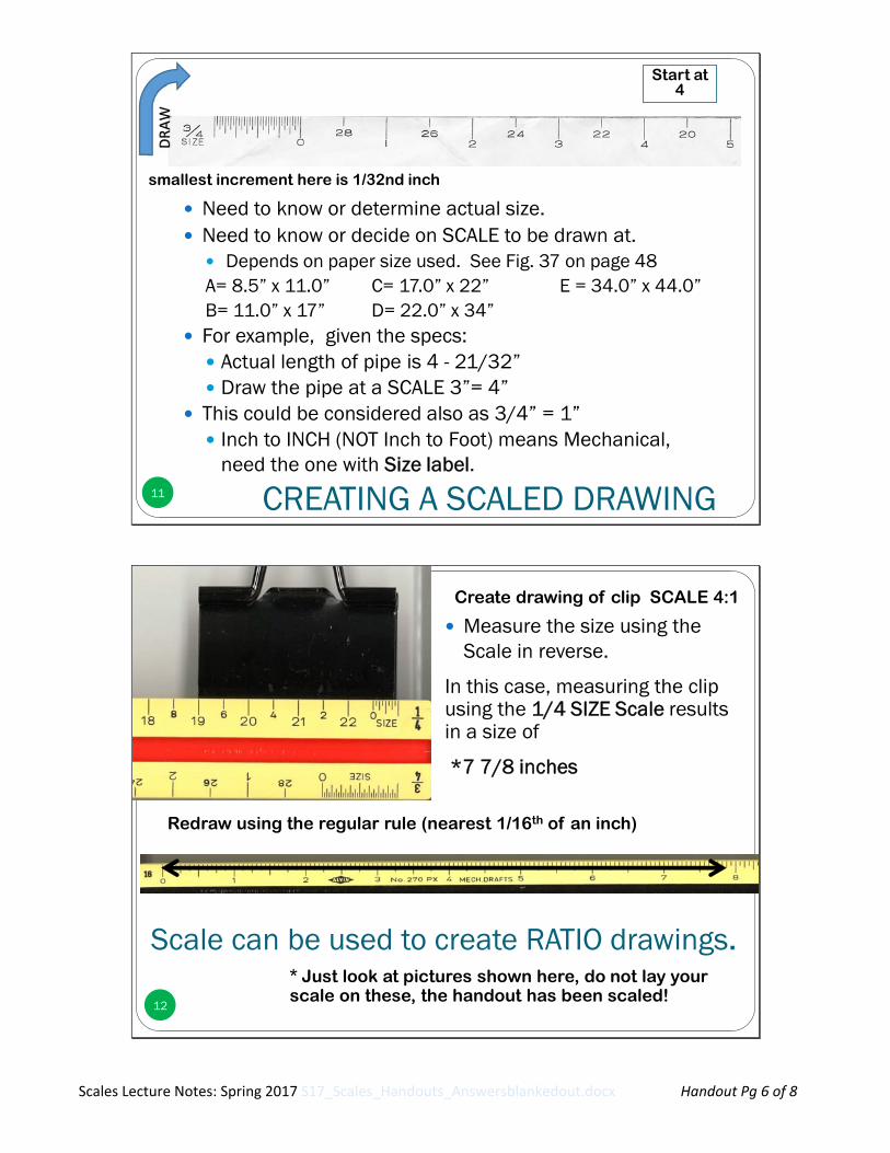
CREATING A SCALED DRAWING11
Need to know or determine actual size. Need to know or decide on SCALE to be drawn at.
Depends on paper size used. See Fig. 37 on page 48A= 8.5” x 11.0” C= 17.0” x 22” E = 34.0” x 44.0”B= 11.0” x 17” D= 22.0” x 34”
For example, given the specs: Actual length of pipe is 4 - 21/32” Draw the pipe at a SCALE 3”= 4”
This could be considered also as 3/4” = 1” Inch to INCH (NOT Inch to Foot) means Mechanical,
need the one with Size label.
Start at 4
smallest increment here is 1/32nd inch
Scale can be used to create RATIO drawings.
12
* Just look at pictures shown here, do not lay your scale on these, the handout has been scaled!
Redraw using the regular rule (nearest 1/16th of an inch)
Create drawing of clip SCALE 4:1
Measure the size using the Scale in reverse.
In this case, measuring the clip using the 1/4 SIZE Scale results in a size of
*7 7/8 inches
DRAW

Scales Lecture Notes: Spring 2017 S17_Scales_Handouts_Answersblankedout.docx Handout Pg 7 of 8
SCALES and CAD Create elements as
“REAL” size ie make it “FULL SIZE”
PLOT at different scales EASILY without having to redraw the elements. Let the program do the
work. Engineering Graphics
usually DO NOT print to fit.
13
Do not use Fit to Paper
We’ve been using 1:1 but there are other options.
See CAD at Work on pg. 52

Scales Lecture Notes: Spring 2017 S17_Scales_Handouts_Answersblankedout.docx Handout Pg 8 of 8
SCALES Lecture: WORKSHEET