Embed Size (px)
Citation preview

Version OS 1.0
Mod.Brane 11Euro-Rack Analog Membrane Synthesizer Module
Operating Manual
Mod.Brane 11 Operating Manual 1
Version OS 1.0
ContentsIntroduction.............................................................................................41. Installation...........................................................................................5
1.1. Installation in the eurorack.............................................................62. Front connections.................................................................................8
2.1. CV1-CV4........................................................................................82.2. LIN.FM..........................................................................................92.3. Gate..............................................................................................92.4. Trigger..........................................................................................92.5. Out..............................................................................................10
3. General functions................................................................................103.1. Preset selection < P00-P99 >......................................................103.2. Menu control................................................................................103.3. Midi control..................................................................................12
3.3.1. Note trigger...........................................................................123.3.2. Parameter control via Midi controllers.....................................12
3.4. Triggering via CV/Gate.................................................................123.5. Triggering via TRIG......................................................................12
4. Sound parameters (potentiometers).....................................................134.1. M1 Pitch < 000-252 > ..............................................................144.2. M1 Dampen < 000-252>............................................................144.3. M2 Pitch < 000-252 > ..............................................................144.4. M2 Dampen < 000-252>............................................................144.5. 1_2 Couplg < 000-252 >............................................................154.6. 2_1 Couplg < (-128)-124 >........................................................154.7. Noise < 000-252 > ...................................................................154.8. Decay < 000-252 > .................................................................16
5. Sound parameters (menu orange/red)................................................175.1. LFO............................................................................................175.1.1. LFO 1 Wave < SuP / Sdo / Sin / Si- / tri / tr- / rCt / rC- >............175.1.2. LFO 1 Speed < 000-252 >........................................................185.1.3. LFO 1 Int(ensity) < 000-252 >..................................................185.1.4. LFO 1 Destination <LM1/no1>..................................................195.1.5. LFO 2.......................................................................................195.2. Gate T(ime) (page orange) < 000-255> .......................................19
2 Mod.Brane 11 Operating Manual
Version OS 1.0
5.2.1. Preset Init (page red) <in?>.....................................................195.3. Noiz Flt (page red) < 000-255 > ...............................................205.4. Met Nze 1 (page orange) < off/noi-499 > ...................................205.4.1. MetNze 2 (page red) < off-499 > .............................................205.4.2. MetNze 2 Bit Mask (page red blinks) <M01-M16>.......................215.5. CV 1-4.........................................................................................215.5.1. CV 1-4 Destination (page orange)...............................................215.5.2. CV 1-4 Amount (page red) <-128 - 127>....................................22
6. Master parameters (menu green)........................................................236.1. Midi Ch(annel) < 001 - 016 >.....................................................236.2. Split Mode < SM1 / SM2 >.........................................................236.3. Trig Sens < t01- t99 >.............................................................236.3.1. Trig Dynamics < d01- d63 >...................................................246.4. Gate Mode <PoS/neg/Str)..........................................................246.5. Volume < 000-255 >..................................................................246.6. Bus Vol < 000-255 >..................................................................256.7. Bus Send < 000-255 >...............................................................256.8. Store...........................................................................................256.9. Technical functional description.....................................................25
7. Mod.Brane 11 Midi Implementation......................................................287.1. SysEx Dump.............................................................................287.1.1. Single preset dump................................................................287.1.2. All presets dump....................................................................287.1.3. Receive SysEx dump..............................................................28
7.2. Sound Parameter CC....................................................................297.3. Note Commands...........................................................................307.4. System exclusive data..................................................................30
Mod.Brane 11 Operating Manual 3
Version OS 1.0
Introduction
Thanks for using the JoMoX Mod.Brane 11! The Mod.Brane 11 is a great sounding, dedicated percussion module with a real analog sound production made for installation in 19 inch euroracks as offered by companies like Doepfer GmbH for instance. Actually it is a single voice storeable analog synthesizer which is optimized to produce professional percussion and snaredrum-like sounds. The Mod.Brane 11 module is fully controllable by CV (control voltage) / Gate as well as via Midi. The module can also be triggered by a drumpad piezo or an external audio signal. All jacks are being made as 3.5mm mini jacks which is the standard in eurorack world. You can find suitable cables in the accessories of many eurorack modular system producing companies.
The usage is fairly simple and self-explaining at most points. Nevertheless, we recommend to study this manual intensively in order to explore the manyfold musical possibilities of the Mod.Brane 11 as quickly as possible.
Before we start just some important safety instructions:
• Please use the Mod.Brane 11 only in dry rooms. Please never let fluids or humidity penetrate to the device!
• The module is only made for use in so-called eurorack modular systems. A 16 pin ribbon cable for the connection to the Doepfer system bus with +/-12V is added. The supply voltages may not exceed +/- 15Volts. Although there are protection diodes inside against wrong polarity we have to warn you about wrong installation as severe damadge may happen to the device! On a damadge caused by wrong installation or modification of supply pins the warranty is void.
• For cleansing of the Mod.Brane 11, please use a slightly damp cloth, never solvents or agents!
• The Mod.Brane 11 is a complex electronic device and should therefore be treated carefully!
If any damadges or malfunctions occur, please immediatly turn off the rack, take the module out of the rack and contact your local music dealer or send an email to [email protected].
4 Mod.Brane 11 Operating Manual
Version OS 1.0
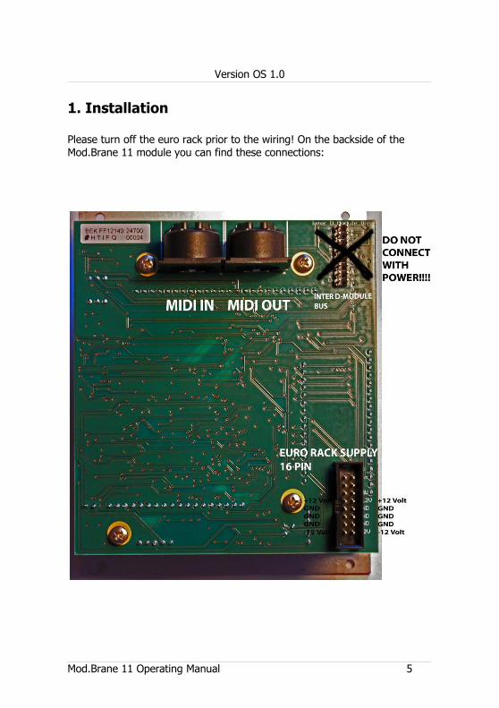
1. Installation
Please turn off the euro rack prior to the wiring! On the backside of the Mod.Brane 11 module you can find these connections:
Mod.Brane 11 Operating Manual 5
Version OS 1.0
1.1. Installation in the eurorack
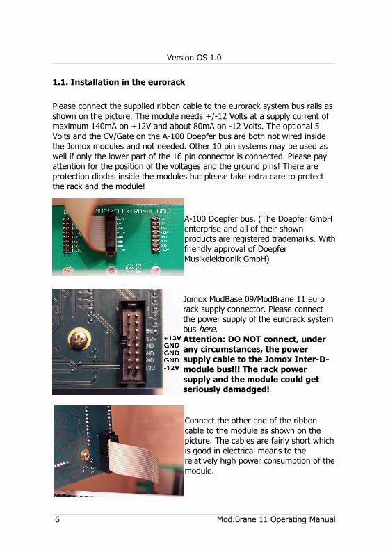
Please connect the supplied ribbon cable to the eurorack system bus rails as shown on the picture. The module needs +/-12 Volts at a supply current of maximum 140mA on +12V and about 80mA on -12 Volts. The optional 5 Volts and the CV/Gate on the A-100 Doepfer bus are both not wired inside the Jomox modules and not needed. Other 10 pin systems may be used as well if only the lower part of the 16 pin connector is connected. Please pay attention for the position of the voltages and the ground pins! There are protection diodes inside the modules but please take extra care to protect the rack and the module!
A-100 Doepfer bus. (The Doepfer GmbH enterprise and all of their shown products are registered trademarks. With friendly approval of Doepfer Musikelektronik GmbH)
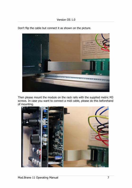
Jomox ModBase 09/ModBrane 11 euro rack supply connector. Please connect the power supply of the eurorack system bus here.Attention: DO NOT connect, under any circumstances, the power supply cable to the Jomox Inter-D-module bus!!! The rack power supply and the module could get seriously damadged!
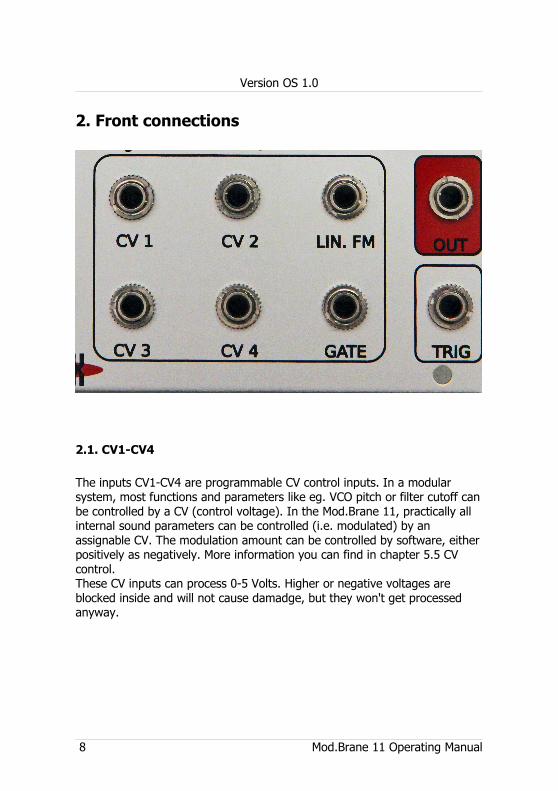
Connect the other end of the ribbon cable to the module as shown on the picture. The cables are fairly short which is good in electrical means to the relatively high power consumption of the module.
6 Mod.Brane 11 Operating Manual
Version OS 1.0
Don't flip the cable but connect it as shown on the picture.
Then please mount the module on the rack rails with the supplied metric M3 screws. In case you want to connect a midi cable, please do this beforehand of mounting.
Mod.Brane 11 Operating Manual 7
Version OS 1.0
2. Front connections
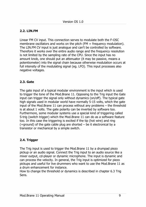
2.1. CV1-CV4
The inputs CV1-CV4 are programmable CV control inputs. In a modular system, most functions and parameters like eg. VCO pitch or filter cutoff can be controlled by a CV (control voltage). In the Mod.Brane 11, practically all internal sound parameters can be controlled (i.e. modulated) by an assignable CV. The modulation amount can be controlled by software, either positively as negatively. More information you can find in chapter 5.5 CV control.These CV inputs can process 0-5 Volts. Higher or negative voltages are blocked inside and will not cause damadge, but they won't get processed anyway.
8 Mod.Brane 11 Operating Manual
Version OS 1.0
2.2. LIN.FM
Linear FM CV input. This connection serves to modulate both the F-OSC membrane oscillators and works on the pitch (FM = frequency modulation). The LIN.FM CV input is just analogue and can't be controlled by software. Therefore it works over the entire audio range and the frequency resolution is not limited by the sampling rate of the CPU. Since the input has no amount knob, one should put an attenuator (it may be passive, means a potentiometer) into the signal chain because otherwise modulation occurs at full intensity of the modulating signal (eg. LFO). This input processes also negative voltages.
2.3. Gate
The gate input of a typical modular environment is the input which is used to trigger the tone of the Mod.Brane 11. Opposing to the Trig input the Gate input can trigger the signal only without dynamics (on/off). The typical gate high signals used in modular world have normally 5-15 volts, which the gate input of the Mod.Brane 11 can process without any problems – the threshold is at about 1 volts. The gate polarity can be inverted by software too. Furthermore, some modular systems use a special kind of triggering called S-trig (switch trigger) which the Mod.Brane 11 can do as a software feature too. In this case the triggering is excited if the tip (hot wire) and ring (=ground) of the gate cable plug are shorted – be it electronical by a transistor or mechanical by a simple switch.
2.4. Trigger
The Trig input is used to trigger the Mod.Brane 11 by a drumpad piezo pickup or an audio signal. Connect the Trig input to an audio source like a mixer output, cd-player or dynamic microphone. The input is dynamic and can process the velocity. In general, the Trig input is optimized for piezo pickups and useful for live drummers who want to use the Mod.Brane 11 as a drum enhancement for instance. How to change the threshold or dynamics is described in chapter 6.3 Trig Sens.
Mod.Brane 11 Operating Manual 9
Version OS 1.0
2.5. Out
Audio ouput signal of the Mod.Brane 11. The ouput is unbalanced and has a maximum level of about +20 dBu, so it can be very loud and may overdrive high gain inputs. Therefore connect the audio output with an appropriate attenuator/mixer or amplifier.
3. General functions
3.1. Preset selection < P00-P99 >
As long none of the 8 menu LEDs is lit, the Mod.Brane 11 is in preset mode. Now you can choose one of 100 preprogrammed presets by turning the value input wheel. The sounds get loaded automatically.
By hitting the play button the sounds can be manually triggered and heard.
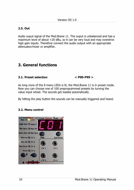
3.2. Menu control
10 Mod.Brane 11 Operating Manual
Version OS 1.0
The Mod.Brane 11 has an up/down menu with 8 rows and 3 pages which are shown by multi-colored LEDs.Please use the arrow buttons to enter the menu and to select the desired menu item and the page button to switch between the three pages green (left printing), orange (right printing) and red (right printing).Repeated pressing of the page button switches first from green to orange, then to red and then in opposite direction backwards.Some pages do have 4 pages (eg. Met Nze) which is shown by blinking of the red LED.If you press the page button whilst the menu is inactive you step automatically to LFO 1 menu (menu 1 orange). This was made because the LFO is an important function and shares the three lower potentiometers with the other sound parameters. In order not to be forced to press two buttons first you can enter the LFO 1 menu by just pressing the page button.With all other menu functions the value gets edited by the value input wheel (alpha dial).
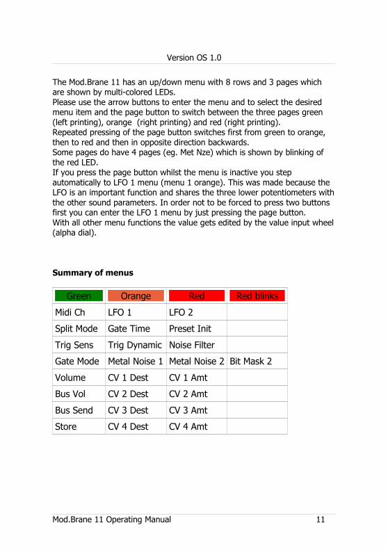
Summary of menus
Green Orange Red Red blinks
Midi Ch LFO 1 LFO 2
Split Mode Gate Time Preset Init
Trig Sens Trig Dynamic Noise Filter
Gate Mode Metal Noise 1 Metal Noise 2 Bit Mask 2
Volume CV 1 Dest CV 1 Amt
Bus Vol CV 2 Dest CV 2 Amt
Bus Send CV 3 Dest CV 3 Amt
Store CV 4 Dest CV 4 Amt
Mod.Brane 11 Operating Manual 11
Version OS 1.0
3.3. Midi control
3.3.1. Note trigger
The Mod.Brane 11 processes midi note commands. It can be triggered by any midi sequencer. If the Mod.Brane 11 receives midi data on the selected channel, the leftmost decimal point in the display lights up. Please find the settings of the various midi functions in chapter 7 Midi Implementation.
3.3.2. Parameter control via Midi controllers
All sound parameters can be remotely controlled by continuous midi controllers (CCs). The controller map can be found in the Midi Implementation at the end of this operating manual.
3.4. Triggering via CV/Gate
Please connect a typical modular gate/trigger CV sequencer (like eg. the Doepfer A-155) to the Gate jack. The Mod.Brane 11 processes gate signals from 0..1 volts to 0..15 volts. To get retriggered, the signal must at least once drop below the trigger threshold, which is a little below 1 volts. If the module is triggered, the second decimal dot next to the second digit of the display flashes up. The gate input triggers always with maximum velocity and has no dynamics. It is strongly recommended to use the GATE input for triggering via a modular sequencer or any other gate-like signals like LFOs!!
3.5. Triggering via TRIG
The jack TRIG is an analog input which allows for triggering the Mod.Brane 11 by a drumpad piezo or audio signal. The trigger input is dynamic and provides attack velocity. It works in parallel to the Midi and Gate trigger, i.e. it allows for playing notes on the keyboard, triggering by a sequencer via gate and triggering by a drum pad at the same time. Also one could play it via Trig in and change sound parameters via Midi CC at the same time. If the Trig input of the Mod.Brane 11 receives a signal, the decimal point next to the second digit of the display flashes up.
12 Mod.Brane 11 Operating Manual

Version OS 1.0
4. Sound parameters (potentiometers)
In order to enter the edit mode, please press <Edit/Enter>. A dot right down in the display lights up indicating that you are in edit mode. Now turn one of the knobs and you will see a value in the display and hear the change of sound. If you press <Edit/Enter> again, the edit mode indicator dot is lit weaker. This is the fine tune mode. Since the whole adjustable range is very large (almost the entire audio range) you have the ability to control the pitch of the membrane oscillators much finer. Whilst hitting the <Edit/Enter> button the second time, the current coarse value is defined as the new center value of the fine tune mode.If you don't want sound paramers to be changed by unwanted knob movements, press <Edit/Enter> once again to leave the edit mode. The edit mode indicator dot fades.
Mod.Brane 11 Operating Manual 13
Version OS 1.0
The Mod.Brane 11 has a dedicated potentiometer knob for the 8 most important parameters. Some sound parameters are only being changed via the LED menu and the incremental wheel though. There is a double assignment for the three knobs in the lower row for the settings of the LFOs.
4.1. M1 Pitch < 000-252 >
This parameter controls the pitch of the first membrane oscillator M1 (F-OSC). The range goes from about 25Hz to 14kHz. Please note that the pitch is also little affected by the settings of M1 Dampen and both coupling parameters 1_2 Couplg and 2_1 Couplg. Because of the sensitive analog circuitry, these values interfere each other a little bit so that re-adjustment of values may be neccessary to achieve a special sound.
4.2. M1 Dampen < 000-252>
By the parameter M1 dampen you change the decay of sound, means the dampen of F-OSC M1. If turned up, M1 fades longer and becomes a steadily vibrating oscillator. A low value lets the F-OSC M1 decay very short.
4.3. M2 Pitch < 000-252 >
This parameter controls the pitch of the second membrane oscillator M2 (F-OSC). The range goes from about 25Hz to 14kHz. Other than that, the same qualities yield like in 4.1. M1 Pitch described.
4.4. M2 Dampen < 000-252>
By the parameter M2 Dampen you change the decay of sound, means the dampen of F-OSC M2. Other than that, the same qualities yield like in 4.2. M1 Dampen described.
14 Mod.Brane 11 Operating Manual
Version OS 1.0
4.5. 1_2 Couplg < 000-252 >
This parameter determines the coupling between M1 and M2. As mentioned in the general functional description, you can simulate the actions of two coupled membranes in a real drum. The parameter 1_2 Coupling adds a part of the bandpass output of M1 to M2 and performs a little bit frequency modulation too.
4.6. 2_1 Couplg < (-128)-124 >
This parameter determines the coupling between M2 and M1. This value can be either positive or negative. This controls at which phase (+/-) the bandpass signal is coupled (added) from M2 into M1. Zero is the initial setting at which no interference occurs. If both coupling parameters have the same sign, they gain each other and create a feedback vibration of both F-OSC which sometimes can result in scream-like sounds if both F-OSCs have the same pitch or are in an octave or 5th relation. At opposing signs, they attenuate each other. Like 1_2 Coupling, 2_1 Coupling performs a little frequency modulation M2 -> M1 too.By playing with these two parameters you can create those wave interferences and interactions that are characteristic for membrane-like percussion sounds.
4.7. Noise < 000-252 >
The noise signal creates the snare drum noise or metallic attacks. The parameter Noise controls the intensity of this signal. As can be seen in Pic.1, the noise signal is processed by a noise envelope and is then mixed into the F-OSC network and a small portion into the final VCA.In the F-OSC network, the noise mixes up with the hit (trigger pulse) and the F-OSC sounds in a similar way like in a real snare drum and reaches a fairly homogeneous sound. If Noise is cranked up too much (>180) it may lead to internal distortions that might be desired though. Also the level and sound of the noise is affected by the noise filter settings too(see 5.3 Noiz Fil).The noise may be either random white noise (MetNze 1 = <noi>) or metallic noise made up by thousands of combinations of MetNze 1 and/or MetNze 2.
Mod.Brane 11 Operating Manual 15
Version OS 1.0
4.8. Decay < 000-252 >
Controls the decay time (length) of the Mod.Brane 11. As can be seen in chapt. 6.9 functional despcription Pic.1, this value controls either the noise envelope and the final VCA envelope. The noise envelope is always shorther than the final VCA envelope in order to adjust the noise attacks precisely, whilst the decay of F-OSC M1 and M2 are mostly controlled by parameter Dampen.
16 Mod.Brane 11 Operating Manual
Version OS 1.0
5. Sound parameters (menu orange/red)
Summary of menus
Green Orange Red Red blinks
Midi Ch LFO 1 LFO 2
Split Mode Gate Time Preset Init
Trig Sens Trig Dynamic Noise Filter
Gate Mode Metal Noise 1 Metal Noise 2 Bit Mask 2
Volume CV 1 Dest CV 1 Amt
Bus Vol CV 2 Dest CV 2 Amt
Bus Send CV 3 Dest CV 3 Amt
Store CV 4 Dest CV 4 Amt
5.1. LFO
Use the up/down buttons and go to LFO.Choose page 2 (LED lights up orange) by pressing the Page button so that the display shows LM1.As long as you are in preset selection mode (no menu) you can just press the page button and you will enter the LFO 1 menu directly. This was made in order to quickly edit the LFO section whilst tweaking the knobs and to flip between both areas.
5.1.1. LFO 1 Wave < SuP / Sdo / Sin / Si- / tri / tr- / rCt / rC- >
Now turn potentiometer 5 (1_2 Coupl, Wave) to change the waveform of LFO 1. The value is shown in the display. LFO 1 always works firmly on the pitch of membrane M1.With the LFO (Low Frequency Oscillator) you can produce periodic low frequency pitch modulations (vibrato).
Mod.Brane 11 Operating Manual 17
Version OS 1.0
The polarity is important because the LFO phase always restarts on a note trigger. That makes the LFO like an extra pitch envelope which gets triggered by the note.This parameter controls the waveform:
<SuP> Sawtooth up<Sdo> Sawtooth down<Sin> Sine wave rising<Si-> Sine wave falling<tri> Triangle with rising ramp<tr-> Triangle with falling ramp<rCt> Rectangular jump from minimum to maximum<rC-> Rectangular jump from maximum to to minimum <PL1> Pulse width 60% on / 40% off<PL2> Pulse width 70% on / 30% off<PL3> Pulse width 80% on / 20% off<PL4> Pulse width 88% on / 12% off<PL5> Pulse width 40% on / 60% off<PL6> Pulse width 30% on / 70% off<PL7> Pulse width 20% on / 80% off<PL8> Pulse width 12% on / 88% off
5.1.2. LFO 1 Speed < 000-252 >
Turn Potentiometer 6 (2_1 Coupl, Speed) to edit the speed of LFO 1. The value is shown in the display. LFO 1 always works on the pitch of the membrane M1.Speed controls the frequency of LFO modulation. Low value = slow, high value = fast. The phase of the LFO always restarts with a gate trigger.
5.1.3. LFO 1 Int(ensity) < 000-252 >
Turn Potentiometer 7 (Noise, Int) to edit the intensity of LFO 1. The value is shown in the display. LFO 1 always works on the pitch of membrane M1.
LFO 1 Intensity controls the amount of modulation. Zero turns the modulation off.
18 Mod.Brane 11 Operating Manual
Version OS 1.0
5.1.4. LFO 1 Destination <LM1/no1>
Whilst the menu LFO is selected, dial the value with the wheel to change the modulation target of LFO 1. Default-wise the LFO works on the pitch of the membrane oscillator M1, but you can also let it modulate metallic noise 1. The result are noise modulations in the rhythm of the LFO which can sound pretty interesting.
5.1.5. LFO 2
Go to LFO with the up/down buttons. Select page 3 (menu LED lights red) by pressing the page button so that the the display shows LM2. If you are still in preset mode (no menu), you can reach the LFO 2 menu by pressing the page button twice.The same values yield for LFO 2 as described for LFO 1. LFO 2 works on the pitch of the membrane oscillator M2 or on metallic noise generator 2.
5.2. Gate T(ime) (page orange) < 000-255>
If you are in one of the following menus, please dial in the value with the wheel (alpha dial).The gate time, i.e. the impulse length of the trigger pulse for both the membrane circuitries M1 and M2 can be adjusted from 0.1ms to 15ms.This parameter is very influent for the sound of the attack and the decaying tone. The shorter the gate time is, the more high frequencies the spectrum of the attack contains, but the less energy is put into membrane circuitries causing a weaker envelope.
5.2.1. Preset Init (page red) <in?>
This menu serves to initialize a preset. If you turn the data wheel to the right, all sound parameters are changed to the default value. The display shows “ini“ then.
Attention! If you didn't store the sound before, all settings are gone.
Mod.Brane 11 Operating Manual 19
Version OS 1.0
5.3. Noiz Flt (page red) < 000-255 >
Behind the noise level control there is a simple 6 dB/octave low pass filter which can make the noise a bit more dull. A strong filtering of noise with a 6 dB/octave filter is also known as “pink noise“. The noise loses its sharpness if you lower this value. At <255> the filter is opened and lets all high frequencies pass through with a slight mid-peak at 4kHz. At <000> the noise signal is turned off.
5.4. Met Nze 1 (page orange) < off/noi-499 >
Metallic noise 1 is one of the both noise generators. The parameter changes the noise to a metallic noise which consists of periodic asyncronous bit patterns. With <oFF> the noise generator is turned off, <noi> yields a static random noise (white noise).On values above that <2-499> a complex signal formed from digital multitones and bit patterns is produced. Each value represents a unique sound pattern which is not smoothly changing across the range but jumps to various sounds one by one. They remind more of a caleidoscope rather than a linear scale. But they give you interesting results for any adjustment, so please play the game of trial and error.Metallic Noise 1 yields a more aperiodic signal which results in more noise-like sounds. This is useful for eg. cowbell-like sounds.Metallic Noise 2 is more periodic and has an adjustable bit mask.
5.4.1. MetNze 2 (page red) < off-499 >
Metallic noise 2 is another noise generator which offers a more periodic (tone-like) metallic noise algorithm. The basic character of noise 2 can be varied a lot by an adjustable bit mask (which yields only for noise 2).Both noise generators get mixed by hardware. Therefore the noise level increases significantly if both noise generators are on. The signals interfere and produce new noise patterns then.
20 Mod.Brane 11 Operating Manual
Version OS 1.0
5.4.2. MetNze 2 Bit Mask (page red blinks) <M01-M16>
This parameter defines the bit mask for noise generator 2. Small values produce very high frequencies in combination with the metallic noise 2 parameter, high values produce longer periodic signals. To hear changes on this parameter please check that metallic noise generator 2 isn't turned off. With low values for bit mask some numbers of metallic noise may produce silence by phase cancellation or may sound the same with every consecutive number so that only the lower numbers are relevant.
5.5. CV 1-4
The CV inputs are able to modulate a wide variety of sound parameters. The inputs process voltages from 0..5 volts and can be assigned to a list of modulation targets. Furthermore, the modulation amount can be adjusted for every CV individually and can be negative too.
5.5.1. CV 1-4 Destination (page orange)
Choose the desired CV modulation destination by turning the value dial:
Display Funktion Realtime Mod.
1Pi Membran 1 Pitch yes
1dP Membran 1 Dampen yes
2Pi Membran 2 Pitch yes
2dP Membran 2 Dampen yes
1Co Coupling 1_2 yes
2Co Coupling 2_1 yes
noi Noise yes
dEC Decay no
noF Noise Filter yes
1ME Metallic Noise 1 yes
2ME Metallic Noise 2 yes
Mod.Brane 11 Operating Manual 21
Version OS 1.0
1Lr LFO 1 Rate yes
1Li LFO 1 Intensity yes
2Lr LFO 2 Rate yes
2Li LFO 2 Intensity yes
5.5.2. CV 1-4 Amount (page red) <-128 - 127>
This parameter controls the modulation amount of CV1 and its selected target. Please note that this value may be negative too. In this case the CV gets subtracted from the parameter. For instance, if you have chosen M1 pitch as destination it makes the tone the lower the higher the CV is.The here described adjustments yield for the four programmable inputs CV1-CV4 which are almost all the same. You can also route multiple CVs on one parameter which get added. However, it is not possible to modulate several parameters with one CV because this would be too much for the processing power of the CPU and eventually lead to artifacts.Because the CVs are sampled by the CPU the maximum frequency resolution is at about 500Hz.Hint:Some CV targets of the instrument can't be modulated in realtime! This is because the hardware spots the value only in the very moment of triggering and can't change it after that because the sound just decays in the circuitry. With those parameters it makes only sense to change the value right before or during the trigger, as does for instance the A-155 of Doepfer. If the tone already sounds (and decays), the CV cannot change anything on this parameter.This yields for:
Decay and its connected two envelopes (noise and membranes).
22 Mod.Brane 11 Operating Manual
Version OS 1.0
6. Master parameters (menu green)
6.1. Midi Ch(annel) < 001 - 016 >
Midi channel on which the Mod.Brane 11 receives and transmits Midi data.Received are: note on/off, note number, program change, controllers. Transmitted are: note on/off, note number, program change.
6.2. Split Mode < SM1 / SM2 >
<SM1> The percussion instrument is only played on standard note D1 (GM standard snare drum) with the internal pitch (4.2 Pitch).<SM2> Note range C1-C2. The note within the octave is added to the pitch of M1 and M2.<SM3> Note range C2-C3. The note within the octave is added to the pitch of M1 and M2.<SM4> Note range C3-C4. The note within the octave is added to the pitch of M1 and M2.<SM5> Note range C1-C6. The percussion instrument is played across the entire keyboard, and the note gets added to the pitch of M1 and M2. Please note that due to the used analog circuitry it is not possible to play the membrane oscillators in exact semitone intervals. All parameters like pitch, dampen and coupling are affecting each other and the ranges are way to large. You should better see it as a tool to obtain different tunings and sounds on a direct access.
6.3. Trig Sens < t01- t99 >
Adjusts the trigger threshold. It is the incoming level from which on the kickdrum gets triggered via TRIG in. If this menu is selected, the LED column works as a VU meter which shows the incoming trigger of the connected pick up (eg. drumpad piezo). A weak lit red LED point roughly shows the trigger threshold from which on the sound gets triggered. If you dial the value with the wheel, the weak red LED point goes up or down.
Mod.Brane 11 Operating Manual 23
Version OS 1.0
6.3.1. Trig Dynamics < d01- d63 >
Controls the trigger dynamics. From the trigger threshold on the incoming velocity is multiplied with the dynamics and adapted to the adjusted volume. A low value kills the dynamics and keeps the sound on the same loudness, a high value enables maximum velocity.
6.4. Gate Mode <PoS/neg/Str)
The gate input can process signals from 0..15 volts, yet it triggers at about 1 volts. In position “PoS“ = positive (default), the signal must rise from 0 to at least 1.5 volts in order to properly trigger the Mod.Brane 11. After that, the gate signal has to fall again under the threshold down to 0 volts to be able to trigger again. Far most of the available sequencers deliver such gate signals – and it works regardless if the high level of the switching voltage is 5 volts, 8 volts or 15 volts.
In position “neg“ = negative, the gate is inverted. That means, it triggers when a transit from high to low occurs and can only retrigger if the gate signal has safely risen above 1 volts again.
Some older sequencers only provide a so-called s-trigger (switch-trigger) – this is useful with position “Str“ = switch-trigger. Now the hot wire of the gate cable has to be shorted with ground in order to trigger the unit. It can be a mechanical switch, but in most cases it will be a transistor with open collector which works as a switch. With the usage of a mechanical switch you have to consider that the input is not debounced – you'd have to add a capacitor (roughly 47nF, just a guess) and solder it across the pins of the switch to reduce contact bouncing and multiple triggers.
6.5. Volume < 000-255 >
Adjusts the main volume of the Mod.Brane 11. The maximum velocity of incoming midi notes get only processed to this level. For the best sounding results, you should keep it at <255>.
24 Mod.Brane 11 Operating Manual
Version OS 1.0
6.6. Bus Vol < 000-255 >
Controls the bus volume of the Mod.Brane 11 on the Inter-D-Module Bus. This is intended for future applications which make use of the bus and can process a globally storeable mix of several Jomox modules.
6.7. Bus Send < 000-255 >
Controls the effects send level of the Mod.Brane 11 on the Inter-D-Module Bus. This is intended for future applications which make use of the bus and that have access to the efffects send bus. We can think of a Jomox effects module (e.g. a filter with reverb) that picks up the various effects send signals from the bus and that creates an effects program for the master mix bus, to which every sound module and every preset can set an individual effects intensity.
6.8. Store
If you want to save a well sounding preset, go on Store. In case you are not in a menu yet (preset mode) you can also press the up arrow button to automatically reach the Store menu. The green LED must blink and the display shows the currently selected preset.Now you can dial the memory location with the data wheel to store the new preset into. Pressing the Edit/Enter button finally executes the storeing and overwrites the existing preset. If you don't move the data wheel, the current preset gets overrriden. This too implements an automatic copy function as the Mod.Brane 11 produces an identical copy of the preset if you store a non-edited preset to another location via Store and dial location.
6.9. Technical functional description
The Mod.Brane 11 is a true analog synthesizer optimized for percussion sounds. The most important parts of the sound are composed by a membrane-like F-OSC network and noise being mixed together.
Mod.Brane 11 Operating Manual 25
Version OS 1.0
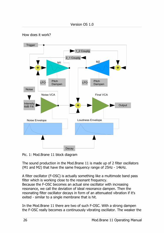
How does it work?
Pic. 1: Mod.Brane 11 block diagram
The sound production in the Mod.Brane 11 is made up of 2 filter oscillators (M1 and M2) that have the same frequency range of 25Hz - 14kHz.
A filter oscillator (F-OSC) is actually something like a multimode band pass filter which is working close to the resonant frequency. Because the F-OSC becomes an actual sine oscillator with increasing resonance, we call the deviation of ideal resonance dampen. Then the resonating filter oscillator decays in form of an attenuated vibration if it's exited - similar to a single membrane that is hit.
In the Mod.Brane 11 there are two of such F-OSC. With a strong dampen the F-OSC really becomes a continuously vibrating oscillator. The weaker the
26 Mod.Brane 11 Operating Manual
M1 M2
Final VCA
Trigger
1_2 Couplg
2_1 Couplg
PitchDampen
PitchDampen
Noise VCA
Noise Envelope Loudness Envelope
++
+ Output
Noise
Decay
LFOLFO
Intensity6dB Filt
Version OS 1.0
dampen is, the more the F-OSC becomes a filter with sharp q-factor (quality). This can be useful at e.g. snare drums or hihat-ish sounds.
Looking at the drumskins of an acoustic drum, there are 2 membranes positioned that modulate and interact with each other by the coupling through pressure waves of the content air. That produces the typical sound of a drum. By resonance and counteractive interference of waves new frequency bands and overtones create.Similar to that the parameter Coupling works at the Mod.Brane 11. Both, in the first place independently vibrating F-OSCs, can attenuate or gain the vibration of the partner by means of coupling on either ways (1_2 and 2_1). With lightfingered tweaking you get these interesting membrane-like dampened sounds, especially by cross-wise positive/negative coupling. In order to obtain such a phase-wise cross coupling, the parameter 2_1 Coupling provides negative values too and has a phase flipping circuitry build in.Furthermore, a slight frequency modulation is provided with every coupling parameter (M1 M2 and M2 M1) that makes the cross modulation sound→ → even more natural and interesting.
In order to create snaredrum- or cowbell-like sounds, the Mod.Brane 11 has a noise generator with an own envelope. A part of this signal is fed into the F-OSC network to exite the "membrane" with the noise signal itself. Another part of the noise signal ist mixed into the final VCA (Voltage Controlled Amplifier) which produces the overall volume envelope of the resulting instrument. The noise can be wether white noise or metallic noise, which is a binary pattern of different metallic sounding frequency bands. In the Mod.Brane 11, there are two independent noise generators which can be mixed together.
The length of noise decay and the decay of the resulting tone are controlled by two different envelopes that are commonly controlled by the parameter Decay. The noise envelope is always shorter than the final VCA envelopes. That lets you work out the precise noise attacks by tweaking the Decay. The F-OSC's mostly have their own decay themselves (changed by Dampen), and they only sometimes need an own (and then longer) loudness envelope.
Two independent LFOs can modulate each of both F-OSCs or not. They always restart with the note trigger and work like an additional pitch envelope.In Split Modes 2-5 both the F-OSC's pitch can be played over the keyboard via Midi, which again makes it a creative thing to play.
Mod.Brane 11 Operating Manual 27
Version OS 1.0
7. Mod.Brane 11 Midi Implementation
7.1. SysEx Dump
The memory contents of Mod.Brane 11 (that is the presets) can be transferred to a Midi sequencer by SySex dump. The current single preset including the number can be transmitted or received or the whole memory contents.
7.1.1. Single preset dump
Please select the Store menu (Menu LED 8 green blinks) at the Mod.Brane 11. Now press record at the connected midi device (we strongly recommend the newest Jomox SysEx Dumper tool). Then press the Play button on the Mod.Brane 11. The current active preset is sent as a midi dump.
7.1.2. All presets dump
Please select the Bus Send menu (Menu LED 7 green) at the Mod.Brane 11.
Now press record at the connected midi device (we strongly recommend the newest Jomox SysEx Dumper tool). Then press the Play button on the Mod.Brane 11. The whole memory contents is sent via SysEx dump. The display reads “bSY“ during the dumping and “Fin“ if the dump has been finished.
7.1.3. Receive SysEx dump
Please select the Midi Ch menu (Menu LED 1 green) at the Mod.Brane 11 and do not change anything.Now start the connected Midi sequencer (we strongly recommend the newest Jomox SysEx Dumper tool because of the required flash memory cycle times). The SysEx data are sent to the Mod.Brane 11 which receives them as presets, displays the preset number and stores the data into the according preset.
28 Mod.Brane 11 Operating Manual
Version OS 1.0
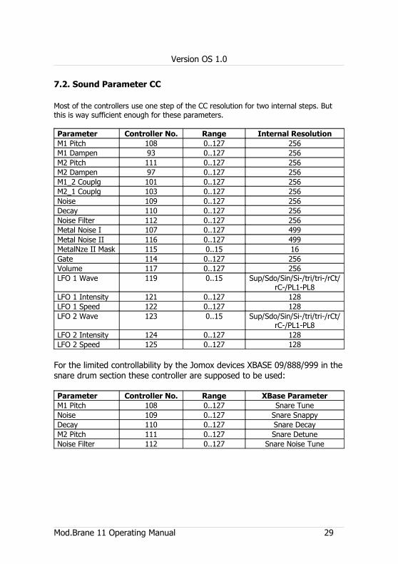
7.2. Sound Parameter CC
Most of the controllers use one step of the CC resolution for two internal steps. But this is way sufficient enough for these parameters.
Parameter Controller No. Range Internal ResolutionM1 Pitch 108 0..127 256M1 Dampen 93 0..127 256M2 Pitch 111 0..127 256M2 Dampen 97 0..127 256M1_2 Couplg 101 0..127 256M2_1 Couplg 103 0..127 256Noise 109 0..127 256Decay 110 0..127 256Noise Filter 112 0..127 256Metal Noise I 107 0..127 499Metal Noise II 116 0..127 499MetalNze II Mask 115 0..15 16Gate 114 0..127 256Volume 117 0..127 256LFO 1 Wave 119 0..15 Sup/Sdo/Sin/Si-/tri/tri-/rCt/
rC-/PL1-PL8LFO 1 Intensity 121 0..127 128LFO 1 Speed 122 0..127 128LFO 2 Wave 123 0..15 Sup/Sdo/Sin/Si-/tri/tri-/rCt/
rC-/PL1-PL8LFO 2 Intensity 124 0..127 128LFO 2 Speed 125 0..127 128
For the limited controllability by the Jomox devices XBASE 09/888/999 in the snare drum section these controller are supposed to be used:
Parameter Controller No. Range XBase ParameterM1 Pitch 108 0..127 Snare TuneNoise 109 0..127 Snare SnappyDecay 110 0..127 Snare DecayM2 Pitch 111 0..127 Snare DetuneNoise Filter 112 0..127 Snare Noise Tune
Mod.Brane 11 Operating Manual 29
Version OS 1.0
7.3. Note Commands
Split Mode 1 Split Mode 2 Split Mode 3 Split Mode 4 Split Mode 5
Note (Midi Number)
D1(38) C1(36)-C2(48)
C2(48)-C3(60)
C3(60)-C4(72)
C1(36)-C6(96)
7.4. System exclusive data
Since the sound control via Midi is entirely made with CC controllers, SysEx data are only used for sending and receiving presets. One line of system exclusive commands looks like the following:
$F0(SysEx Begin), $31(JoMoX Manufact. code), $7F(Command Sys Ex Dump), $5a(Product Code), $XX(Preset No.),XX(Data0),XX(Data1),..., $F7(End of SysEx)
32 bytes [bit7...bit0] (0..255) of data per preset are transferred. They are split into two 7-bit midi bytes: MSB [bit7] in Data0 and LSB [bit6...bit0] in Data1. The MSB (most significant bit) is coded in Data0 = 1 or = 0, depending if bit 7 of the actual byte was set or cleared.The numbers and digits of Sys Ex sequences are shown, as always, in hexadecimal numbers.
And finally...Service, tips and tricks:
JoMoX GmbHKörtestr. 10 10967 Berlin / Germany
http://www.jomox.c om
We wish you lots of fun on creative usage of our products!
© 2014Jürgen Michaelis
30 Mod.Brane 11 Operating Manual


![BAB III RESONATOR MEMS 3.1 OSILATORlib.ui.ac.id/file?file=digital/133505-T 27903-Perancangan...Gambar 3.4. Ilustrasi sebuah resonator micromachined folded-beam comb-drive.[28] Struktur](https://img.pdfslide.tips/doc/110x75/60f7d0f4c37102649b347476/bab-iii-resonator-mems-31-27903-perancangan-gambar-34-ilustrasi-sebuah-resonator.jpg)