Embed Size (px)
Citation preview
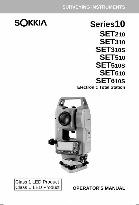
SURVEYING INSTRUMENTS
Series10SET210SET310
SET310SSET510
SET510SSET610
SET610SElectronic Total Station
OPERATOR'S MANUALClass 1 LED ProductClass LED Product
SET310_C1C2.fm 1 ページ 2002年5月17日 金曜日 午後6時20分

:This is the mark of the Japan SurveyingInstruments Manufacturers Association.
Li-ion S Li-ion
SET310_C1C2.fm 2 ページ 2002年8月19日 月曜日 午後1時15分
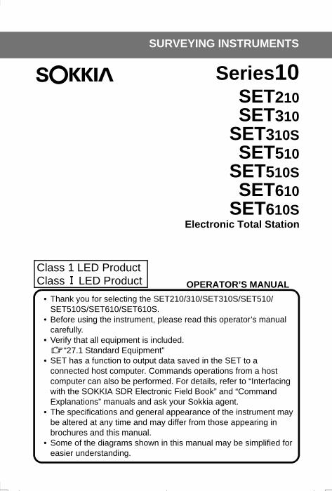
SURVEYING INSTRUMENTS
OPERATOR’S MANUAL• Thank you for selecting the SET210/310/SET310S/SET510/
SET510S/SET610/SET610S.• Before using the instrument, please read this operator’s manual
carefully.• Verify that all equipment is included.
“27.1 Standard Equipment”• SET has a function to output data saved in the SET to a
connected host computer. Commands operations from a host computer can also be performed. For details, refer to “Interfacing with the SOKKIA SDR Electronic Field Book” and “Command Explanations” manuals and ask your Sokkia agent.
• The specifications and general appearance of the instrument may be altered at any time and may differ from those appearing in brochures and this manual.
• Some of the diagrams shown in this manual may be simplified for easier understanding.
Class 1 LED ProductClass LED Product
Series10SET210SET310
SET310SSET510
SET510SSET610
SET610SElectronic Total Station
SET310_C1C2.fm 3 ページ 2002年5月17日 金曜日 午後6時20分
CONTENTS
ii
1. PRECAUTIONS FOR SAFE OPERATION . . . . . . . . . 12. PRECAUTIONS . . . . . . . . . . . . . . . . . . . . . . . . . . . . . . 5
3. HOW TO READ THIS MANUAL . . . . . . . . . . . . . . . . . 74. SET FUNCTIONS . . . . . . . . . . . . . . . . . . . . . . . . . . . . 8
4.1 Parts of the Instrument . . . . . . . . . . . . . . . . . . . . 84.2 Mode Diagram . . . . . . . . . . . . . . . . . . . . . . . . . 10
5. BASIC OPERATION . . . . . . . . . . . . . . . . . . . . . . . . . 115.1 Basic Key Operation . . . . . . . . . . . . . . . . . . . . . 115.2 Display Functions . . . . . . . . . . . . . . . . . . . . . . . 14
6. USING THE BATTERY . . . . . . . . . . . . . . . . . . . . . . . 166.1 Battery Charging . . . . . . . . . . . . . . . . . . . . . . . . 166.2 Installing / Removing the Battery . . . . . . . . . . . 17
7. SETTING UP THE INSTRUMENT . . . . . . . . . . . . . . 197.1 Centering . . . . . . . . . . . . . . . . . . . . . . . . . . . . . 197.2 Levelling . . . . . . . . . . . . . . . . . . . . . . . . . . . . . . 20
8. FOCUSSING AND TARGET SIGHTING . . . . . . . . . . 249. POWER ON . . . . . . . . . . . . . . . . . . . . . . . . . . . . . . . . 26
10. ANGLE MEASUREMENT . . . . . . . . . . . . . . . . . . . . . 2710.1 Measuring the Horizontal Angle between Two
Points (Horizontal Angle 0°) . . . . . . . . . . . . . . . 2710.2 Setting the Horizontal Angle to a Required Value
(Horizontal Angle Hold) . . . . . . . . . . . . . . . . . . 2810.3 Horizontal Angle Repetition . . . . . . . . . . . . . . . 2910.4 Angle Measurement and Outputting the Data . 30
11. DISTANCE MEASUREMENT . . . . . . . . . . . . . . . . . . 3111.1 Distance and Angle Measurement . . . . . . . . . . 3211.2 Recalling the Measured Data . . . . . . . . . . . . . . 3311.3 Distance Measurement and
Outputting the Data . . . . . . . . . . . . . . . . . . . . . 3411.4 REM Measurement . . . . . . . . . . . . . . . . . . . . . . 35
12. COORDINATE MEASUREMENT . . . . . . . . . . . . . . . 3712.1 Entering Instrument Station Data . . . . . . . . . . . 3712.2 Azimuth Angle Setting . . . . . . . . . . . . . . . . . . . 4012.3 3-D Coordinate Measurement . . . . . . . . . . . . . 42
READ THISFIRST
INTRODUCTION
PREPARATIONFORMEASURE-MENT
MEASURE-MENT-MEASURE-MENTMODE -
SET310TOC.fm ii ページ 2001年12月11日 火曜日 午前9時44分
CONTENTS
iii
13. RESECTION MEASUREMENT . . . . . . . . . . . . . . . . . 4413.1 Coordinate Resection Measurement . . . . . . . . 4513.2 Height Resection Measurement . . . . . . . . . . . . 48
14. SETTING-OUT MEASUREMENT . . . . . . . . . . . . . . . 5214.1 Distance Setting-out Measurement . . . . . . . . . 5214.2 Coordinates Setting-out Measurement . . . . . . . 5614.3 REM Setting-out Measurement . . . . . . . . . . . . 58
15. SETTING-OUT LINE . . . . . . . . . . . . . . . . . . . . . . . . . 6015.1 Defining Baseline . . . . . . . . . . . . . . . . . . . . . . . 6015.2 Setting-out Line Point . . . . . . . . . . . . . . . . . . . . 6315.3 Setting-out Line Line . . . . . . . . . . . . . . . . . . . . . 64
16. POINT PROJECTION . . . . . . . . . . . . . . . . . . . . . . . . 6716.1 Defining Baseline . . . . . . . . . . . . . . . . . . . . . . . 6716.2 Point Projection . . . . . . . . . . . . . . . . . . . . . . . . 68
17. OFFSET MEASUREMENT . . . . . . . . . . . . . . . . . . . . 7017.1 Single-distance Offset Measurement . . . . . . . . 7017.2 Angle Offset Measurement . . . . . . . . . . . . . . . . 7217.3 Two-distance Offset Measurement . . . . . . . . . . 74
18. MISSING LINE MEASUREMENT . . . . . . . . . . . . . . . 7618.1 Measuring the Distance between
2 or more Points . . . . . . . . . . . . . . . . . . . . . . . . 7618.2 Changing the Starting Point . . . . . . . . . . . . . . . 78
19. SURFACE AREA CALCULATION . . . . . . . . . . . . . . 7920. RECORDING DATA - RECORD MENU - . . . . . . . . . 83
20.1 Recording Instrument Station Data . . . . . . . . . 8320.2 Recording Angle Measurement Data . . . . . . . . 8520.3 Recording Distance Measurement Data . . . . . . 8620.4 Recording Coordinate Data . . . . . . . . . . . . . . . 8720.5 Recording Distance and Coordinate Data . . . . 8820.6 Recording Notes . . . . . . . . . . . . . . . . . . . . . . . . 8920.7 Reviewing JOB Data . . . . . . . . . . . . . . . . . . . . 89
MEASURE-MENT-MEASURE-MENTMODE -
SET310TOC.fm iii ページ 2001年12月11日 火曜日 午前9時44分
CONTENTS
iv
21. SELECTING / DELETING A JOB . . . . . . . . . . . . . . . 9121.1 Selecting a JOB . . . . . . . . . . . . . . . . . . . . . . . . 9121.2 Deleting a JOB . . . . . . . . . . . . . . . . . . . . . . . . . 93
22. REGISTERING/DELETING DATA . . . . . . . . . . . . . . 9522.1 Registering/Deleting Known Point Data . . . . . . 9522.2 Reviewing Known Point Data . . . . . . . . . . . . . . 9822.3 Registering/Deleting Codes . . . . . . . . . . . . . . . 9822.4 Reviewing Codes . . . . . . . . . . . . . . . . . . . . . . . 99
23. OUTPUTTING JOB DATA . . . . . . . . . . . . . . . . . . . . 100
24. CHANGING THE SETTINGS . . . . . . . . . . . . . . . . . 10224.1 Changing Instrument Options . . . . . . . . . . . . . 10224.2 Allocating Key Functions . . . . . . . . . . . . . . . . 10824.3 Restoring Default Settings . . . . . . . . . . . . . . . 111
25. WARNING AND ERROR MESSAGES . . . . . . . . . . 11326. CHECKS AND ADJUSTMENTS . . . . . . . . . . . . . . . 116
26.1 Plate Level . . . . . . . . . . . . . . . . . . . . . . . . . . . 11626.2 Circular Level . . . . . . . . . . . . . . . . . . . . . . . . . 11726.3 Tilt Sensor . . . . . . . . . . . . . . . . . . . . . . . . . . . 11826.4 Collimation . . . . . . . . . . . . . . . . . . . . . . . . . . . 12226.5 Reticle . . . . . . . . . . . . . . . . . . . . . . . . . . . . . . . 12326.6 Optical plummet . . . . . . . . . . . . . . . . . . . . . . . 12426.7 Additive Distance Constant . . . . . . . . . . . . . . 126
27. STANDARD EQUIPMENT AND OPTIONAL ACCESSORIES . . . . . . . . . . . . . . . . . . . . . . . . . . . . 12827.1 Standard Equipment . . . . . . . . . . . . . . . . . . . . 12827.2 Optional Accessories . . . . . . . . . . . . . . . . . . . 13027.3 Target System . . . . . . . . . . . . . . . . . . . . . . . . 13327.4 Power Supply System . . . . . . . . . . . . . . . . . . 135
28. SPECIFICATIONS . . . . . . . . . . . . . . . . . . . . . . . . . . 13729. REGULATIONS . . . . . . . . . . . . . . . . . . . . . . . . . . . . 14130. EXPLANATION . . . . . . . . . . . . . . . . . . . . . . . . . . . . 144
30.1 Manually Indexing the Vertical Circle by Face Left, Face Right Measurement . . . . . . . 144
TROUBLE-SHOOTING
MANAGING THEDATA-MEMORYMODE-
ADDITIONALDETAILSMODE-
INFORMATIONABOUTSET
SET310TOC.fm iv ページ 2002年2月15日 金曜日 午前11時39分
1
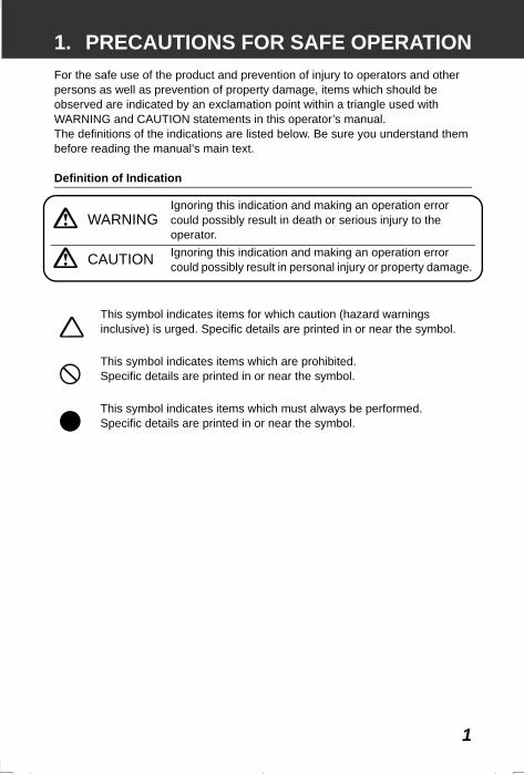
1. PRECAUTIONS FOR SAFE OPERATIONFor the safe use of the product and prevention of injury to operators and other persons as well as prevention of property damage, items which should be observed are indicated by an exclamation point within a triangle used with WARNING and CAUTION statements in this operator’s manual.The definitions of the indications are listed below. Be sure you understand them before reading the manual’s main text.
Definition of Indication
WARNINGIgnoring this indication and making an operation error could possibly result in death or serious injury to the operator.
CAUTION Ignoring this indication and making an operation error could possibly result in personal injury or property damage.
This symbol indicates items for which caution (hazard warnings inclusive) is urged. Specific details are printed in or near the symbol.
This symbol indicates items which are prohibited.Specific details are printed in or near the symbol.
This symbol indicates items which must always be performed.Specific details are printed in or near the symbol.
SET2120_01.fm 1 ページ 2001年12月7日 金曜日 午後1時21分
1. PRECAUTIONS FOR SAFE OPERATION
2
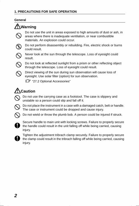
General
Warning
Caution
Do not use the unit in areas exposed to high amounts of dust or ash, in areas where there is inadequate ventilation, or near combustible materials. An explosion could occur.Do not perform disassembly or rebuilding. Fire, electric shock or burns could result.Never look at the sun through the telescope. Loss of eyesight could result.Do not look at reflected sunlight from a prism or other reflecting object through the telescope. Loss of eyesight could result.Direct viewing of the sun during sun observation will cause loss of eyesight. Use solar filter (option) for sun observation.
“27.2 Optional Accessories”
Do not use the carrying case as a footstool. The case is slippery and unstable so a person could slip and fall off it.Do not place the instrument in a case with a damaged catch, belt or handle. The case or instrument could be dropped and cause injury.Do not wield or throw the plumb bob. A person could be injured if struck.
Secure handle to main unit with locking screws. Failure to properly secure the handle could result in the unit falling off while being carried, causing injury.Tighten the adjustment tribrach clamp securely. Failure to properly secure the clamp could result in the tribrach falling off while being carried, causing injury.
SET2120_01.fm 2 ページ 2001年12月7日 金曜日 午後1時21分
3
1. PRECAUTIONS FOR SAFE OPERATION
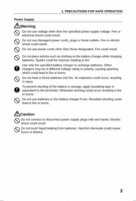
Power Supply
Warning
Caution
Do not use voltage other than the specified power supply voltage. Fire or electrical shock could result.Do not use damaged power cords, plugs or loose outlets. Fire or electric shock could result.Do not use power cords other than those designated. Fire could result.
Do not place articles such as clothing on the battery charger while charging batteries. Sparks could be induced, leading to fire.Use only the specified battery charger to recharge batteries. Other chargers may be of different voltage rating or polarity, causing sparking which could lead to fire or burns.Do not heat or throw batteries into fire. An explosion could occur, resulting in injury.To prevent shorting of the battery in storage, apply insulating tape or equivalent to the terminals. Otherwise shorting could occur resulting in fire or burns.Do not use batteries or the battery charger if wet. Resultant shorting could lead to fire or burns.
Do not connect or disconnect power supply plugs with wet hands. Electric shock could result.Do not touch liquid leaking from batteries. Harmful chemicals could cause burns or blisters.
SET2120_01.fm 3 ページ 2001年12月7日 金曜日 午後1時21分
1. PRECAUTIONS FOR SAFE OPERATION
4
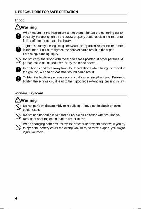
Tripod
Warning
Wireless Keyboard
Warning
When mounting the instrument to the tripod, tighten the centering screw securely. Failure to tighten the screw properly could result in the instrument falling off the tripod, causing injury.Tighten securely the leg fixing screws of the tripod on which the instrument is mounted. Failure to tighten the screws could result in the tripod collapsing, causing injury.Do not carry the tripod with the tripod shoes pointed at other persons. A person could be injured if struck by the tripod shoes.Keep hands and feet away from the tripod shoes when fixing the tripod in the ground. A hand or foot stab wound could result.Tighten the leg fixing screws securely before carrying the tripod. Failure to tighten the screws could lead to the tripod legs extending, causing injury.
Do not perform disassembly or rebuilding. Fire, electric shock or burns could result.Do not use batteries if wet and do not touch batteries with wet hands. Resultant shorting could lead to fire or burns.When changing batteries, follow the procedure described below. If you try to open the battery cover the wrong way or try to force it open, you might injure yourself.
SET310_01.fm 4 ページ 2002年3月6日 水曜日 午後7時29分
5
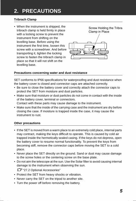
2. PRECAUTIONS Tribrach Clamp
• When the instrument is shipped, the tribrach clamp is held firmly in place with a locking screw to prevent the instrument from shifting on the levelling base. Before using the instrument the first time, loosen this screw with a screwdriver. And before transporting it, tighten the locking screw to fasten the tribrach clamp in place so that it will not shift on the levelling base.
Precautions concerning water and dust resistance
SET conforms to IP66 specifications for waterproofing and dust resistance when the battery cover is closed and connector caps are attached correctly. • Be sure to close the battery cover and correctly attach the connector caps to
protect the SET from moisture and dust particles.• Make sure that moisture or dust particles do not come in contact with the inside
of the battery cover, terminal or connectors.Contact with these parts may cause damage to the instrument.
• Make sure that the inside of the carrying case and the instrument are dry before closing the case. If moisture is trapped inside the case, it may cause the instrument to rust.
Other precautions
• If the SET is moved from a warm place to an extremely cold place, internal parts may contract, making the keys difficult to operate. This is caused by cold air trapped inside the hermetically sealed casing. If the keys do not depress, open the battery cover to resume normal functionality. To prevent the keys from becoming stiff, remove the connector caps before moving the SET to a cold place.
• Never place the SET directly on the ground. Sand or dust may cause damage to the screw holes or the centering screw on the base plate.
• Do not aim the telescope at the sun. Use the Solar filter to avoid causing internal damage to the instrument when observing the sun.
“27.2 Optional Accessories”• Protect the SET from heavy shocks or vibration.• Never carry the SET on the tripod to another site.• Turn the power off before removing the battery.
SET310_02.fm 5 ページ 2001年12月11日 火曜日 午前8時50分
2. PRECAUTIONS
6
• When placing the SET in its case, first remove its battery and place it in the case in accordance with the layout plan.
Maintenance
• Always clean the instrument before returning it to the case. The lens requires special care. First, dust it off with the lens brush to remove tiny particles. Then, after providing a little condensation by breathing on the lens, wipe it with a soft clean cloth or lens tissue.
• If the display is dirty, carefully wipe it with a soft, dry cloth. To clean other parts of the instrument or the carrying case, lightly moisten a soft cloth in a mild detergent solution. Wring out excess water until the cloth is slightly damp, then carefully wipe the surface of the unit. Do not use any organic solvents or alkaline cleaning solutions.
• Store the SET in a dry room where the temperature remains fairly constant.• Check the tripod for loose fit and loose screws.• If any trouble is found on the rotatable portion, screws or optical parts (e.g.
lens), contact your SOKKIA agent.• When the instrument is not used for a long time, check it at least once every 3
months.“26. CHECKS AND ADJUSTMENTS”
• When removing the SET from the carrying case, never pull it out by force. The empty carrying case should be closed to protect it from moisture.
• Check the SET for proper adjustment periodically to maintain the instrument accuracy.
SET310_02.fm 6 ページ 2002年8月20日 火曜日 午後6時19分
7
3. HOW TO READ THIS MANUALSymbols
The following conventions are used in this manual.
: Indicates precautions and important items which should be read before operations.
: Indicates the chapter title to refer to for additional information.
: Indicates supplementary explanation.
: Indicates an explanation for a particular term or operation.
[DIST] etc. : Indicates softkeys on the display.
{ESC} etc. : Indicates operation keys on the SET or wireless keyboard.
<S-O> etc. : Indicates screen titles.
Screens and illustrations
• Except where stated, “SET310” means SET310/SET310S, “SET510” means SET510/SET510S and “SET610” means SET610/610S in this manual.
• Screens and illustrations appearing in this manual are of SET510.• Location of softkeys in screens used in procedures is based on the factory
setting. It is possible to change the allocation of softkeys in Meas Mode.What are softkeys: “4.1 Parts of the Instrument”, Softkeys allocation: “24.2 Allocating Key Functions”
Operation procedure
• Learn basic key operations in “5. BASIC OPERATION” before you read each measurement procedure.
• Measurement procedures are based on continuous measurement. Some information about procedures when other measurement options are selected can be found in “Note” ( ).
• For selecting options and inputting figures, see “5.1 Basic Key Operation”.
SET310_03.fm 7 ページ 2002年5月17日 金曜日 午後6時21分
8
4. SET FUNCTIONS
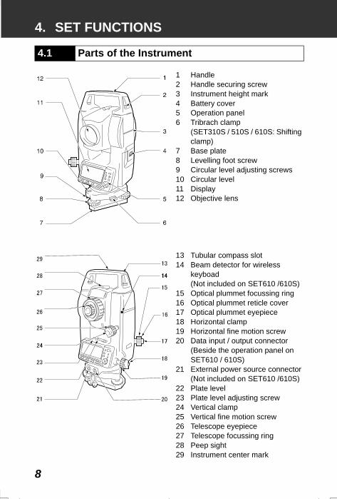
1 Handle2 Handle securing screw3 Instrument height mark4 Battery cover5 Operation panel6 Tribrach clamp
(SET310S / 510S / 610S: Shifting clamp)
7 Base plate8 Levelling foot screw9 Circular level adjusting screws10 Circular level11 Display12 Objective lens
13 Tubular compass slot14 Beam detector for wireless
keyboad(Not included on SET610 /610S)
15 Optical plummet focussing ring16 Optical plummet reticle cover17 Optical plummet eyepiece 18 Horizontal clamp19 Horizontal fine motion screw20 Data input / output connector
(Beside the operation panel on SET610 / 610S)
21 External power source connector(Not included on SET610 /610S)
22 Plate level23 Plate level adjusting screw24 Vertical clamp25 Vertical fine motion screw26 Telescope eyepiece27 Telescope focussing ring28 Peep sight29 Instrument center mark
4.1 Parts of the Instrument
SET2120_04.fm 8 ページ 2001年12月7日 金曜日 午前11時30分
9
4. SET FUNCTIONS
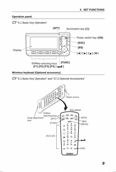
Operation panel
“5.1 Basic Key Operation”
Wireless keyboad (Optional accessory)
“5.1 Basic Key Operation” and “27.2 Optional Accessories”
selecting keys
Key panel
Beam source
Strap attachmenthole
{A} to {Z}
Softkeyselecting keys
{FUNC} {MEAS}
{�}
{SFT}{BS}
{ESC}
{A/N}
SET310_04.fm 9 ページ 2001年12月11日 火曜日 午前10時16分
4. SET FUNCTIONS
10
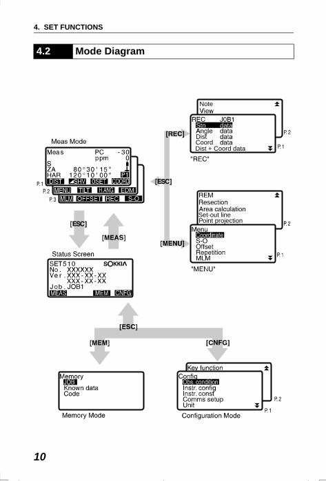
4.2 Mode Diagram
Note
Stn data
Dist CoordDist + Coord data
Set-out linePoint projection
SET310_04.fm 10 ページ 2002年8月19日 月曜日 午後1時14分
11
5. BASIC OPERATION
Learn basic key operations here before you read each measurement procedure.Location of operation keys on the panel and Location of operation keys on the wireless keyboard : “4.1 Parts of the Instrument”
• Wireless keyboard (SF14) (Optional accessory) makes key operation easier and speedier.
Specification of the keyboard: “27.2 Optional Accessories”
Power ON / OFF{ON}: Power On{ON} (while pressing) + { }: Power Off
Lighting up the display{ } : Switch the screen backlight On / Off
Softkey operationSoftkeys are displayed on the bottom line of the screen. {F1} to {F4}: Select the function matching the sofkeys{FUNC} : Toggle between MEAS Mode screen pages (when more than 4
softkeys are allocated)
Inputting letters / figures{F1} to {F4}: Input a letter or a figure allocated to the softkey {FUNC} : Go to the next softkey page (search for the letter or figure you
want to input){FUNC} (hold for a moment): Go back one softkey page{FUNC} (continue to hold): Go to previous softkey pages{BS} : Delete a character on the left{ESC} : Cancel the input data{SFT} : Switch between upper and lower case{ } : Select / accept input word / value
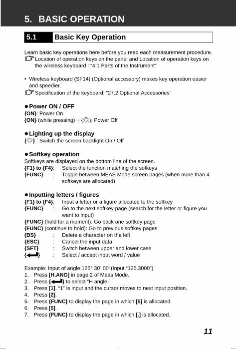
Example: Input of angle 125° 30′ 00″(Input “125.3000”)1. Press [H.ANG] in page 2 of Meas Mode.2. Press { } to select “H angle.”3. Press [1]. “1” is input and the cursor moves to next input position.4. Press [2].5. Press {FUNC} to display the page in which [5] is allocated.6. Press [5].7. Press {FUNC} to display the page in which [.] is allocated.
5.1 Basic Key Operation
SET310_05.fm 11 ページ 2001年12月7日 金曜日 午後5時12分
5. BASIC OPERATION
12
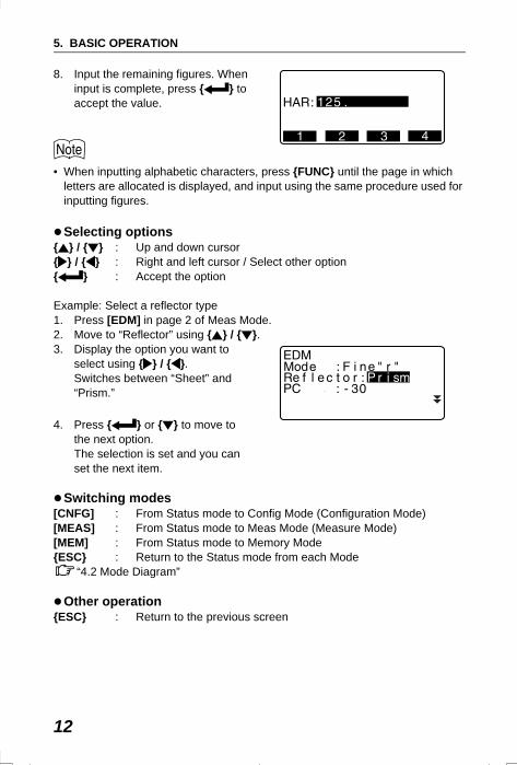
8. Input the remaining figures. When input is complete, press { } to accept the value.
• When inputting alphabetic characters, press {FUNC} until the page in which letters are allocated is displayed, and input using the same procedure used for inputting figures.
Selecting options{ } / { } : Up and down cursor{ } / { } : Right and left cursor / Select other option{ } : Accept the option
Example: Select a reflector type1. Press [EDM] in page 2 of Meas Mode.2. Move to “Reflector” using { } / { }.3. Display the option you want to
select using { } / { }.Switches between “Sheet” and “Prism.”
4. Press { } or { } to move to the next option.The selection is set and you can set the next item.
Switching modes[CNFG] : From Status mode to Config Mode (Configuration Mode)[MEAS] : From Status mode to Meas Mode (Measure Mode)[MEM] : From Status mode to Memory Mode{ESC} : Return to the Status mode from each Mode
“4.2 Mode Diagram”
Other operation{ESC} : Return to the previous screen
SET310_05.fm 12 ページ 2001年12月7日 金曜日 午後5時12分
13
5. BASIC OPERATION
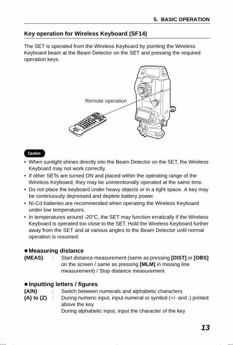
Key operation for Wireless Keyboard (SF14)
The SET is operated from the Wireless Keyboard by pointing the Wireless Keyboard beam at the Beam Detector on the SET and pressing the required operation keys.
• When sunlight shines directly into the Beam Detector on the SET, the Wireless Keyboard may not work correctly.
• If other SETs are turned ON and placed within the operating range of the Wireless Keyboard, they may be unintentionally operated at the same time.
• Do not place the keyboard under heavy objects or in a tight space. A key may be continuously depressed and deplete battery power.
• Ni-Cd batteries are recommended when operating the Wireless Keyboard under low temperatures.
• In temperatures around -20°C, the SET may function erratically if the Wireless Keyboard is operated too close to the SET. Hold the Wireless Keyboard further away from the SET and at various angles to the Beam Detector until normal operation is resumed.
Measuring distance{MEAS} : Start distance measurement (same as pressing [DIST] or [OBS]
on the screen / same as pressing [MLM] in missing line measurement) / Stop distance measurement
Inputting letters / figures{A/N} : Switch between numerals and alphabetic characters{A} to {Z} : During numeric input, input numeral or symbol (+/- and .) printed
above the keyDuring alphabetic input, input the character of the key
Remote operation
SET310_05.fm 13 ページ 2002年2月15日 金曜日 午前10時53分
5. BASIC OPERATION
14
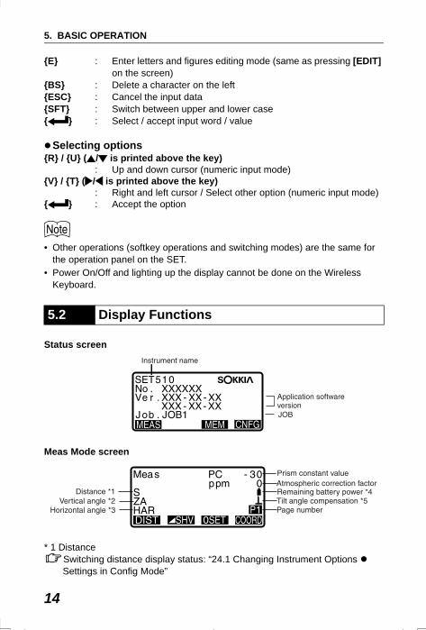
{E} : Enter letters and figures editing mode (same as pressing [EDIT] on the screen)
{BS} : Delete a character on the left{ESC} : Cancel the input data{SFT} : Switch between upper and lower case{ } : Select / accept input word / value
Selecting options{R} / {U} ( / is printed above the key)
: Up and down cursor (numeric input mode){V} / {T} ( / is printed above the key)
: Right and left cursor / Select other option (numeric input mode){ } : Accept the option
• Other operations (softkey operations and switching modes) are the same for the operation panel on the SET.
• Power On/Off and lighting up the display cannot be done on the Wireless Keyboard.
Status screen
Meas Mode screen
* 1 DistanceSwitching distance display status: “24.1 Changing Instrument Options Settings in Config Mode”
5.2 Display Functions
SET310_05.fm 14 ページ 2002年3月6日 水曜日 午後7時30分
15
5. BASIC OPERATION
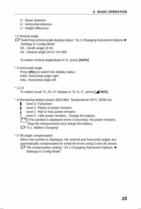
S : Slope distanceH : Horizontal distanceV : Height difference
* 2 Vertical angleSwitching vertical angle display status: “24.1 Changing Instrument Options Settings in Config Mode”ZA : Zenith angle (Z=0)VA : Vertical angle (H=0 / H=±90)
To switch vertical angle/slope in %, press [ZA/%]
* 3 Horizontal anglePress [R/L] to switch the display status.HAR: Horizontal angle rightHAL: Horizontal angle left
* 1,2,3To switch usual “S, ZA, H” display to “S, H, V”, press [ SHV].
* 4 Remaining battery power (BDC46A, Temperature=25°C, EDM on) : level 3 Full power. : level 2 Plenty of power remains. : level 1 Half or less power remains. : level 0 Little power remains. Charge the battery.
(This symbol is displayed every 3 seconds): No power remains. Stop the measurement and charge the battery.
“6.1 Battery Charging”
* 5 Tilt angle compensationWhen this symbol is displayed, the vertical and horizontal angles are automatically compensated for small tilt errors using 2-axis tilt sensor.
Tilt compensation setting: “24.1 Changing Instrument Options Settings in Config Mode”
SET310_05.fm 15 ページ 2002年8月19日 月曜日 午後1時19分
16
6. USING THE BATTERY
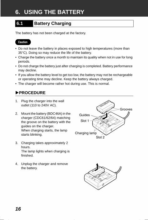
The battery has not been charged at the factory.
• Do not leave the battery in places exposed to high temperatures (more than 35°C). Doing so may reduce the life of the battery.
• Charge the battery once a month to maintain its quality when not in use for long periods.
• Do not charge the battery just after charging is completed. Battery performance may decline.
• If you allow the battery level to get too low, the battery may not be rechargeable or operating time may decline. Keep the battery always charged.
• The charger will become rather hot during use. This is normal.
PROCEDURE
1. Plug the charger into the wall outlet (110 to 240V AC).
2. Mount the battery (BDC46A) in the charger (CDC61/62/64) matching the groove on the battery with the guides on the charger.When charging starts, the lamp starts blinking.
3. Charging takes approximately 2 hours. The lamp lights when charging is finished.
4. Unplug the charger and remove the battery.
6.1 Battery Charging
SET310_06.fm 16 ページ 2002年5月17日 金曜日 午後6時22分
17
6. USING THE BATTERY
• Slots 1 and 2: The charger starts charging the battery mounted first. If you place two batteries in the charger, the battery in slot 1 is charged first, and then the battery in slot 2. (step 2)
• Charging lamp: The charging lamp is off when the charger is outside the charging temperature range or when the battery is mounted incorrectly. If the lamp is still off after the charger falls within its charging temperature range and the battery is mounted again, contact your Sokkia agent. (steps 2 and 3)
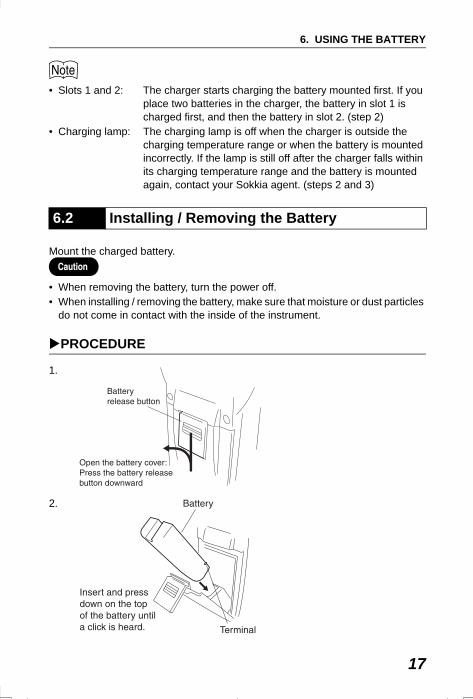
Mount the charged battery.
• When removing the battery, turn the power off.• When installing / removing the battery, make sure that moisture or dust particles
do not come in contact with the inside of the instrument.
PROCEDURE
1.
2.
6.2 Installing / Removing the Battery
SET2120_06.fm 17 ページ 2001年12月7日 金曜日 午前11時31分
6. USING THE BATTERY
18
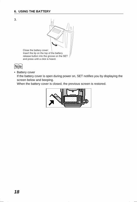
3.
• Battery coverIf the battery cover is open during power on, SET notifies you by displaying the screen below and beeping.When the battery cover is closed, the previous screen is restored.
SET2120_06.fm 18 ページ 2001年12月7日 金曜日 午前11時31分
19
7. SETTING UP THE INSTRUMENT
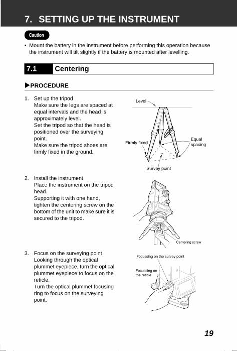
• Mount the battery in the instrument before performing this operation because the instrument will tilt slightly if the battery is mounted after levelling.
PROCEDURE
1. Set up the tripodMake sure the legs are spaced at equal intervals and the head is approximately level.Set the tripod so that the head is positioned over the surveying point.Make sure the tripod shoes are firmly fixed in the ground.
2. Install the instrumentPlace the instrument on the tripod head.Supporting it with one hand, tighten the centering screw on the bottom of the unit to make sure it is secured to the tripod.
3. Focus on the surveying pointLooking through the optical plummet eyepiece, turn the optical plummet eyepiece to focus on the reticle.Turn the optical plummet focusing ring to focus on the surveying point.
7.1 Centering
SET2120_07.fm 19 ページ 2001年12月7日 金曜日 午前11時31分
7. SETTING UP THE INSTRUMENT
20
Instrument can be levelled using the screen.“ Levelling on the screen”
PROCEDURE
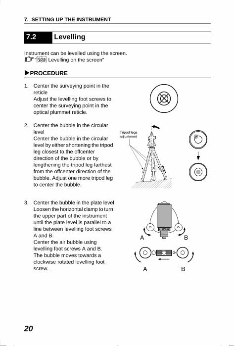
1. Center the surveying point in the reticleAdjust the levelling foot screws to center the surveying point in the optical plummet reticle.
2. Center the bubble in the circular levelCenter the bubble in the circular level by either shortening the tripod leg closest to the offcenter direction of the bubble or by lengthening the tripod leg farthest from the offcenter direction of the bubble. Adjust one more tripod leg to center the bubble.
3. Center the bubble in the plate levelLoosen the horizontal clamp to turn the upper part of the instrument until the plate level is parallel to a line between levelling foot screws A and B.Center the air bubble using levelling foot screws A and B.The bubble moves towards a clockwise rotated levelling foot screw.
7.2 Levelling
SET310_07.fm 20 ページ 2001年12月11日 火曜日 午前9時2分
21
7. SETTING UP THE INSTRUMENT
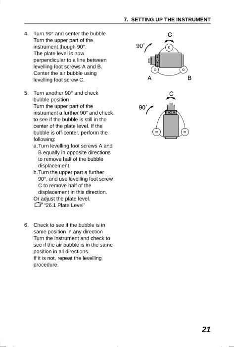
4. Turn 90° and center the bubbleTurn the upper part of the instrument though 90°.The plate level is now perpendicular to a line between levelling foot screws A and B.Center the air bubble using levelling foot screw C.
5. Turn another 90° and check bubble positionTurn the upper part of the instrument a further 90° and check to see if the bubble is still in the center of the plate level. If the bubble is off-center, perform the following:a.Turn levelling foot screws A and
B equally in opposite directions to remove half of the bubble displacement.
b.Turn the upper part a further 90°, and use levelling foot screw C to remove half of the displacement in this direction.
Or adjust the plate level.“26.1 Plate Level”
6. Check to see if the bubble is in same position in any directionTurn the instrument and check to see if the air bubble is in the same position in all directions.If it is not, repeat the levelling procedure.
SET2120_07.fm 21 ページ 2001年12月7日 金曜日 午前11時31分
7. SETTING UP THE INSTRUMENT
22
7. Center the SET over the Surveying point (SET310 / 510 / 610):Loosen the centering screw slightly.Looking through the optical plummet eyepiece, slide the instrument over the tripod head until the surveying point is exactly centered in the reticle.Retighten the centering screw securely.
(SET310S / 510S / 610S):Turn the tribrach shifting clamp counterclockwise. Shifting tribrach can be adjusted up to ±8mm.Looking through the optical plummet eyepiece, adjust the instrument position on the tribrach to center the surveying point.Tighten the shifting clamp to fix the instrument in the center position.
8. Check again to make sure the bubble in the plate level is centeredIf not, repeat the procedure starting from step 3.
SET2120_07.fm 22 ページ 2001年12月7日 金曜日 午前11時31分
23
7. SETTING UP THE INSTRUMENT
PROCEDURE Levelling on the screen
1. Press {ON} to power on
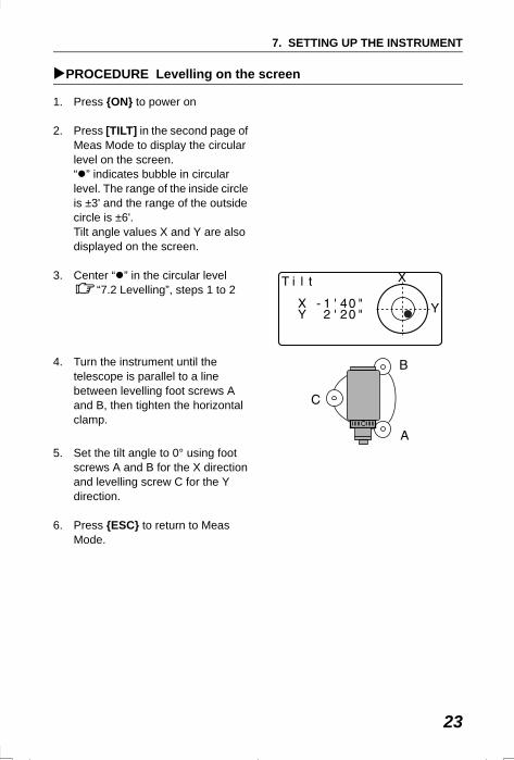
2. Press [TILT] in the second page of Meas Mode to display the circular level on the screen.“ ” indicates bubble in circular level. The range of the inside circle is ±3' and the range of the outside circle is ±6'.Tilt angle values X and Y are also displayed on the screen.
3. Center “ ” in the circular level“7.2 Levelling”, steps 1 to 2
4. Turn the instrument until the telescope is parallel to a line between levelling foot screws A and B, then tighten the horizontal clamp.
5. Set the tilt angle to 0° using foot screws A and B for the X direction and levelling screw C for the Y direction.
6. Press {ESC} to return to Meas Mode.
SET310_07.fm 23 ページ 2002年8月19日 月曜日 午後5時12分
24
8. FOCUSSING AND TARGET SIGHTING
• When sighting the target, strong light shining directly into the objective lens may cause the instrument to malfunction. Protect the objective lens from direct light by attaching the lens hood.Observe to the same point of the reticle when the telescope face is changed.
PROCEDURE
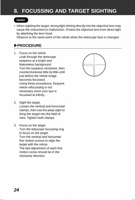
1. Focus on the reticleLook through the telescope eyepiece at a bright and featureless background.Turn the eyepiece clockwise, then counterclockwise little by little until just before the reticle image becomes focussed.Using these procedures, frequent reticle refocussing is not necessary since your eye is focussed at infinity.
2. Sight the targetLoosen the vertical and horizontal clamps, then use the peep sight to bring the target into the field of view. Tighten both clamps.
3. Focus on the targetTurn the telescope focussing ring to focus on the target.Turn the vertical and horizontal fine motion screws to align the target with the reticle.The last adjustment of each fine motion screw should be in the clockwise direction.
SET2120_08.fm 24 ページ 2001年12月7日 金曜日 午前11時32分
25
8. FOCUSSING AND TARGET SIGHTING
4. Readjust the focus until there is no parallaxReadjust the focus with the focussing ring until there is no parallax between the target image and the reticle.
Eliminating parallaxThis is the relative displacement of the target image with respect to the reticle when the observer’s head is moved slightly before the eyepiece.Parallax will introduce reading errors and must be removed before observations are taken. Parallax can be removed by refocussing the reticle.
SET2120_08.fm 25 ページ 2001年12月7日 金曜日 午前11時32分
26
9. POWER ONSetting “V manual”: “24.1 Changing Instrument Options Settings in Config Mode”
PROCEDURE
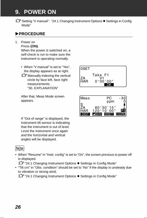
1. Power onPress {ON}.When the power is switched on, a self-check is run to make sure the instrument is operating normally.
• When “V manual” is set to “Yes”, the display appears as at right.
Manually indexing the vertical circle by face left, face right measurements: “30. EXPLANATION”
After that, Meas Mode screen appears.
If “Out of range” is displayed, the instrument tilt sensor is indicating that the instrument is out of level. Level the instrument once again and the horizontal and vertical angles will be displayed.
• When “Resume” in “Instr. config” is set to “On”, the screen previous to power off is displayed.
“24.1 Changing Instrument Options Settings in Config Mode” • “Tilt crn” in “Obs. condition” should be set to “No” if the display is unsteady due
to vibration or strong wind.“24.1 Changing Instrument Options Settings in Config Mode”
SET310_09.fm 26 ページ 2001年12月11日 火曜日 午前9時3分
27
10.ANGLE MEASUREMENTThis section explains the procedures for basic angle measurement.
Use the “0SET” function to measure the included angle between two points. The horizontal angle can be set to 0 at any direction.
PROCEDURE
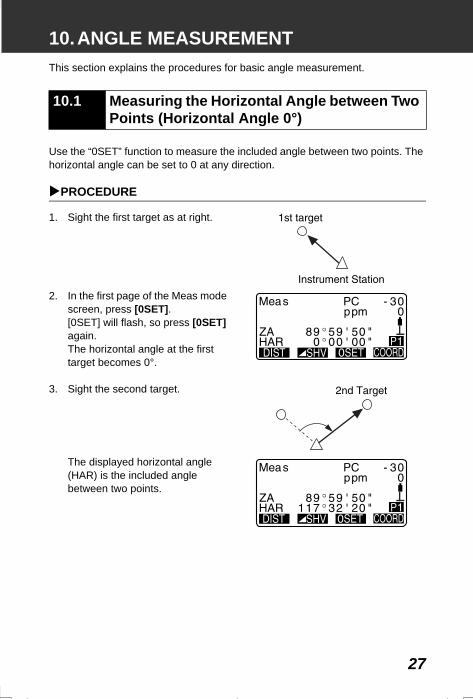
1. Sight the first target as at right.
2. In the first page of the Meas mode screen, press [0SET].[0SET] will flash, so press [0SET] again.The horizontal angle at the first target becomes 0°.
3. Sight the second target.
The displayed horizontal angle (HAR) is the included angle between two points.
10.1 Measuring the Horizontal Angle between Two Points (Horizontal Angle 0°)
SET310_10.fm 27 ページ 2001年12月7日 金曜日 午後5時20分
10. ANGLE MEASUREMENT
28
You can reset the horizontal angle to a required value and use this value to find the horizontal angle of a new target.
PROCEDURE
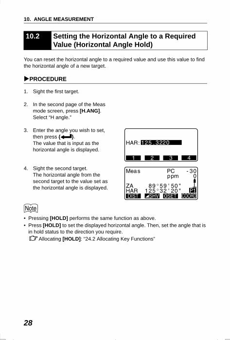
1. Sight the first target.
2. In the second page of the Meas mode screen, press [H.ANG].Select “H angle.”
3. Enter the angle you wish to set, then press { }.The value that is input as the horizontal angle is displayed.
4. Sight the second target.The horizontal angle from the second target to the value set as the horizontal angle is displayed.
• Pressing [HOLD] performs the same function as above.• Press [HOLD] to set the displayed horizontal angle. Then, set the angle that is
in hold status to the direction you require.Allocating [HOLD]: “24.2 Allocating Key Functions”
10.2 Setting the Horizontal Angle to a Required Value (Horizontal Angle Hold)
SET310_10.fm 28 ページ 2001年12月7日 金曜日 午後5時20分
29
10. ANGLE MEASUREMENT
To find the horizontal angle with greater precision, perform repetition measurement.
PROCEDURE
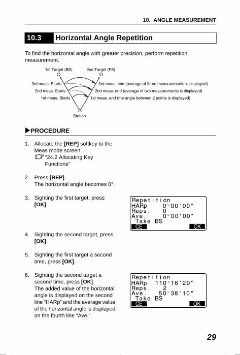
1. Allocate the [REP] softkey to the Meas mode screen.
“24.2 Allocating Key Functions”
2. Press [REP]. The horizontal angle becomes 0°.
3. Sighting the first target, press [OK].
4. Sighting the second target, press [OK].
5. Sighting the first target a second time, press [OK].
6. Sighting the second target a second time, press [OK].The added value of the horizontal angle is displayed on the second line “HARp” and the average value of the horizontal angle is displayed on the fourth line “Ave.”.
10.3 Horizontal Angle Repetition
SET310_10.fm 29 ページ 2001年12月11日 火曜日 午前9時4分
10. ANGLE MEASUREMENT
30
• Return to the previous measurement of the first target and redo it: [CE].(Effective when the display shows “Take BS”)
7. When continuing the repetition measurement, repeat steps 4 to 5.
8. When the repetition measurement is completed, press {ESC}.
• It is also possible to perform repetition measurement when [MENU] on page 2 of the Meas mode screen is pressed to enter <Menu>, then “Repetition” is selected without allocating the function key.
The following explains angle measurement and the features used to output measurement data to a computer or peripheral equipment.
Communication cables: “27.2 Optional Accessories”Output format and command operations: “Interfacing with the SOKKIA SDR Electronic Field Book” and “Command Explanations” manuals.
PROCEDURE
1. Connect SET and host computer.
2. Allocate the [D-OUT] softkey to the Meas mode screen.
“24.2 Allocating Key Functions”
3. Sight the target point.
4. Press [D-OUT] and select “Angle Data.”Output measurement data to peripheral equipment.
10.4 Angle Measurement and Outputting the Data
SET310_10.fm 30 ページ 2001年12月7日 金曜日 午後5時20分
31
11. DISTANCE MEASUREMENTPerform the following four settings as preparation for distance measurement.• Distance measurement mode• Target type• Prism constant correction value• Atmospheric correction factor• EDM Standby• EDM ALC
“24.1 Changing Instrument Options EDM Settings / Settings in Config Mode”
• Check to make sure that sufficient reflected light is returned by the reflective prism sighted by the telescope. Checking the returned signal is particularly useful when performing long distance measurements.
• When the light intensity is sufficient even though the center of the reflective prism and the reticle are slightly misaligned (short distance etc.), “*” will be displayed in some cases, but in fact, accurate measurement is impossible. Therefore make sure that the target center is sighted correctly.
PROCEDURE Returned Signal Checking
1. Allocate the [AIM] softkey to the Meas mode screen.
“24.2 Allocating Key Functions”
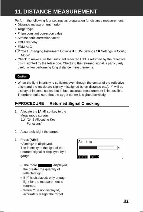
2. Accurately sight the target.
3. Press [AIM].<Aiming> is displayed.The intensity of the light of the returned signal is displayed by a gauge.
• The more displayed, the greater the quantity of reflected light.
• If “*” is displayed; only enough light for the measurement is returned.
• When “*” is not displayed, accurately resight the target.
SET2120_11.fm 31 ページ 2001年12月7日 金曜日 午後1時27分
11. DISTANCE MEASUREMENT
32
• Press [BEEP] to make a buzzer sound when measurement is possible. Press [OFF] to shut off the buzzer.
• Press [DIST] to shift distance measurement.
• When is displayed persistently, contact your Sokkia agent.• If no key operations are performed for two minutes, the display automatically
returns to the Meas mode screen.
An angle can be measured at the same time as the distance.
PROCEDURE
1. Sight the target.
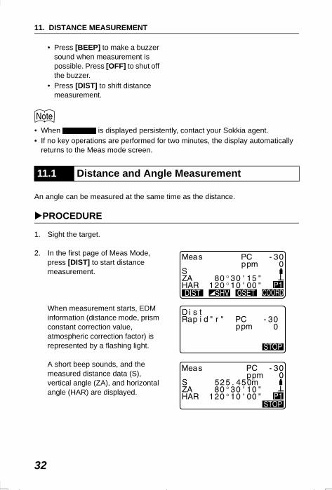
2. In the first page of Meas Mode, press [DIST] to start distance measurement.
When measurement starts, EDM information (distance mode, prism constant correction value, atmospheric correction factor) is represented by a flashing light.
A short beep sounds, and the measured distance data (S), vertical angle (ZA), and horizontal angle (HAR) are displayed.
11.1 Distance and Angle Measurement
SET2120_11.fm 32 ページ 2001年12月7日 金曜日 午後1時27分
33
11. DISTANCE MEASUREMENT
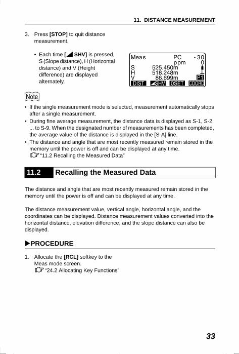
3. Press [STOP] to quit distance measurement.
• Each time [ SHV] is pressed, S (Slope distance), H (Horizontal distance) and V (Height difference) are displayed alternately.
• If the single measurement mode is selected, measurement automatically stops after a single measurement.
• During fine average measurement, the distance data is displayed as S-1, S-2, ... to S-9. When the designated number of measurements has been completed, the average value of the distance is displayed in the [S-A] line.
• The distance and angle that are most recently measured remain stored in the memory until the power is off and can be displayed at any time.
“11.2 Recalling the Measured Data”
The distance and angle that are most recently measured remain stored in the memory until the power is off and can be displayed at any time.
The distance measurement value, vertical angle, horizontal angle, and the coordinates can be displayed. Distance measurement values converted into the horizontal distance, elevation difference, and the slope distance can also be displayed.
PROCEDURE
1. Allocate the [RCL] softkey to the Meas mode screen.
“24.2 Allocating Key Functions”
11.2 Recalling the Measured Data
SET2120_11.fm 33 ページ 2001年12月7日 金曜日 午後1時27分
11. DISTANCE MEASUREMENT
34
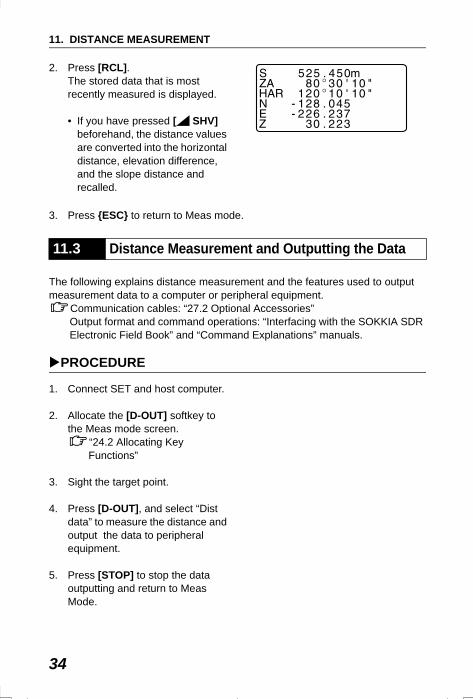
2. Press [RCL].The stored data that is most recently measured is displayed.
• If you have pressed [ SHV] beforehand, the distance values are converted into the horizontal distance, elevation difference, and the slope distance and recalled.
3. Press {ESC} to return to Meas mode.
The following explains distance measurement and the features used to output measurement data to a computer or peripheral equipment.
Communication cables: “27.2 Optional Accessories”Output format and command operations: “Interfacing with the SOKKIA SDR Electronic Field Book” and “Command Explanations” manuals.
PROCEDURE
1. Connect SET and host computer.
2. Allocate the [D-OUT] softkey to the Meas mode screen.
“24.2 Allocating Key Functions”
3. Sight the target point.
4. Press [D-OUT], and select “Dist data” to measure the distance and output the data to peripheral equipment.
5. Press [STOP] to stop the data outputting and return to Meas Mode.
11.3 Distance Measurement and Outputting the Data
SET310_11.fm 34 ページ 2001年12月11日 火曜日 午前9時6分
35
11. DISTANCE MEASUREMENT
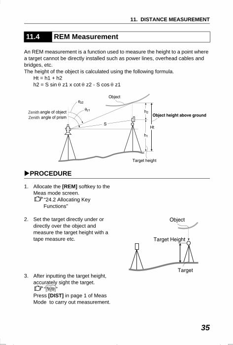
An REM measurement is a function used to measure the height to a point where a target cannot be directly installed such as power lines, overhead cables and bridges, etc.The height of the object is calculated using the following formula.
Ht = h1 + h2h2 = S sin θ z1 x cot θ z2 - S cos θ z1
PROCEDURE
1. Allocate the [REM] softkey to the Meas mode screen.
“24.2 Allocating Key Functions”
2. Set the target directly under or directly over the object and measure the target height with a tape measure etc.
3. After inputting the target height, accurately sight the target.
“ ”Press [DIST] in page 1 of Meas Mode to carry out measurement.
11.4 REM Measurement
ZenithZenith
SET310_11.fm 35 ページ 2002年6月25日 火曜日 午前11時9分
11. DISTANCE MEASUREMENT
36
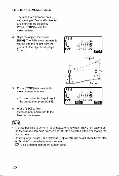
The measured distance data (S), vertical angle (ZA), and horizontal angle (HAR) are displayed. Press [STOP] to stop the measurement.
4. Sight the object, then press [REM]. The REM measurement is started and the height from the ground to the object is displayed in “Ht.”.
5. Press [STOP] to terminate the measurement operation.
• To re-observe the target, sight the target, then press [OBS].
6. Press {ESC} to finish measurement and return to the Meas mode screen.
• It is also possible to perform REM measurement when [MENU] on page 2 of the Meas mode screen is pressed and “REM” is selected without allocating the function key.
• Inputting target height (Step 3): Press [HT] to set target height. It can be set also in “Stn data” of coordinate measurement.
“12.1 Entering Instrument Station Data”
SET310_11.fm 36 ページ 2002年6月25日 火曜日 午前11時9分
37
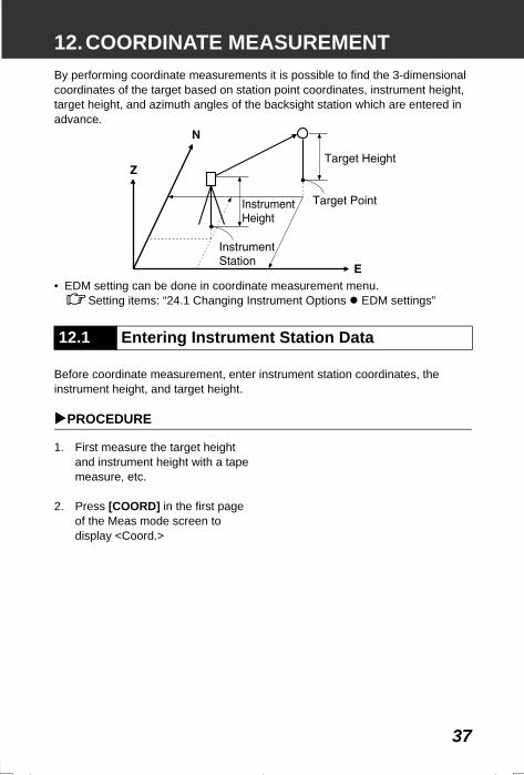
12.COORDINATE MEASUREMENTBy performing coordinate measurements it is possible to find the 3-dimensional coordinates of the target based on station point coordinates, instrument height, target height, and azimuth angles of the backsight station which are entered in advance.
• EDM setting can be done in coordinate measurement menu.Setting items: “24.1 Changing Instrument Options EDM settings”
Before coordinate measurement, enter instrument station coordinates, the instrument height, and target height.
PROCEDURE
1. First measure the target height and instrument height with a tape measure, etc.
2. Press [COORD] in the first page of the Meas mode screen to display <Coord.>
12.1 Entering Instrument Station Data
SET2120_12.fm 37 ページ 2001年12月7日 金曜日 午前11時33分
12. COORDINATE MEASUREMENT
38
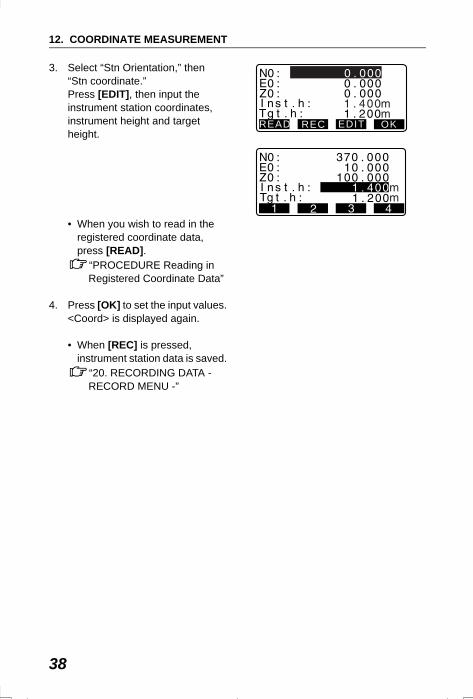
3. Select “Stn Orientation,” then “Stn coordinate.”Press [EDIT], then input the instrument station coordinates, instrument height and target height.
• When you wish to read in the registered coordinate data, press [READ].
“PROCEDURE Reading in Registered Coordinate Data”
4. Press [OK] to set the input values. <Coord> is displayed again.
• When [REC] is pressed, instrument station data is saved.
“20. RECORDING DATA - RECORD MENU -”
0 . 000
READ REC EDIT OK
SET2120_12.fm 38 ページ 2001年12月7日 金曜日 午前11時33分
39
12. COORDINATE MEASUREMENT
PROCEDURE Reading in Registered Coordinate Data
Known point data, coordinate data and instrument station data in the current JOB and Coordinate Search JOB can be read in. Confirm that the correct JOB containing the coordinates you want to read in is already selected in Coordinate Search JOB in Memory Mode.
“22.1 Registering/Deleting Known Point Data”, “21.1 Selecting a JOB”
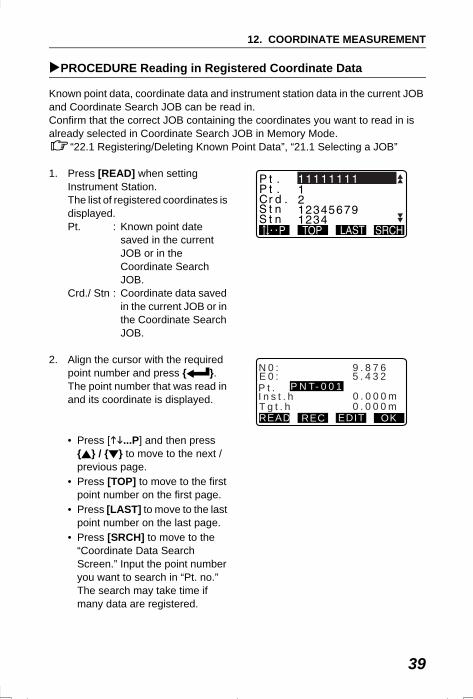
1. Press [READ] when setting Instrument Station.The list of registered coordinates is displayed.Pt. : Known point date
saved in the current JOB or in the Coordinate Search JOB.
Crd./ Stn : Coordinate data saved in the current JOB or in the Coordinate Search JOB.
2. Align the cursor with the required point number and press { }.The point number that was read in and its coordinate is displayed.
• Press [ ...P] and then press { } / { } to move to the next / previous page.
• Press [TOP] to move to the first point number on the first page.
• Press [LAST] to move to the last point number on the last page.
• Press [SRCH] to move to the “Coordinate Data Search Screen.” Input the point number you want to search in “Pt. no.”The search may take time if many data are registered.
0 . 000
P t .I n s t . hT g t . hREAD REC EDIT OK
0 . 0 0 0 m
P N T- 0 0 10 . 0 0 0 m
E 0 : 5 . 4 3 2N 0 : 9 . 8 7 6
SET2120_12.fm 39 ページ 2001年12月7日 金曜日 午前11時33分
12. COORDINATE MEASUREMENT
40
3. Press [OK].<Instrument Station Data Setting> is restored.
• Press [EDIT] to edit the coordinate data that was read in. Editing does not affect the original coordinate data. After editing, the point number is no longer displayed.
• The point number that was read in is displayed until the current JOB is changed.• When [SRCH] is pressed, SET searches data in the current JOB first, then in
the Coordinate Search JOB.• If more than two points with the same point name exist in the current JOB, SET
finds the newer data only.
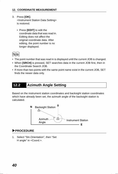
Based on the instrument station coordinates and backsight station coordinates which have already been set, the azimuth angle of the backsight station is calculated.
PROCEDURE
1. Select “Stn.Orientation”, then “Set H angle” in <Coord.>.
12.2 Azimuth Angle Setting
SET2120_12.fm 40 ページ 2001年12月7日 金曜日 午前11時33分
41
12. COORDINATE MEASUREMENT
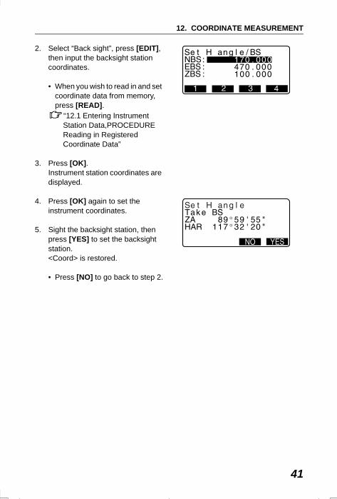
2. Select “Back sight”, press [EDIT], then input the backsight station coordinates.
• When you wish to read in and set coordinate data from memory, press [READ].
“12.1 Entering Instrument Station Data,PROCEDURE Reading in Registered Coordinate Data”
3. Press [OK].Instrument station coordinates are displayed.
4. Press [OK] again to set the instrument coordinates.
5. Sight the backsight station, then press [YES] to set the backsight station. <Coord> is restored.
• Press [NO] to go back to step 2.
SET310_12.fm 41 ページ 2002年2月13日 水曜日 午後2時52分
12. COORDINATE MEASUREMENT
42
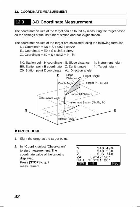
The coordinate values of the target can be found by measuring the target based on the settings of the instrument station and backsight station.
The coordinate values of the target are calculated using the following formulae. N1 Coordinate = N0 + S x sinZ x cosAzE1 Coordinate = E0 + S x sinZ x sinAzZ1 Coordinate = Z0 + S x cosZ + ih - fh
N0: Station point N coordinate S: Slope distance ih: Instrument heightE0: Station point E coordinate Z: Zenith angle fh: Target heightZ0: Station point Z coordinate Az: Direction angle
PROCEDURE
1. Sight the target at the target point.
2. In <Coord>, select “Observation” to start measurement. The coordinate value of the target is displayed. Press [STOP] to quit measurement.
12.3 3-D Coordinate Measurement
E
SET2120_12.fm 42 ページ 2001年12月7日 金曜日 午前11時33分
43
12. COORDINATE MEASUREMENT
• By pressing [HT], the instrument station data can be reset. When the target height of the next target is different, reenter the target height before beginning the observation.
• [REC]: records measurement results
Recording method: “20. RECORDING DATA - RECORD MENU -”
3. Sight the next target and press [OBS] to begin measurement. Continue until all targets have been measured.
4. When coordinate measurement is completed, press {ESC} to return to <Coord>.
SET2120_12.fm 43 ページ 2001年12月7日 金曜日 午前11時33分
44
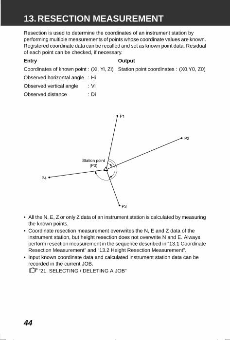
13.RESECTION MEASUREMENTResection is used to determine the coordinates of an instrument station by performing multiple measurements of points whose coordinate values are known. Registered coordinate data can be recalled and set as known point data. Residual of each point can be checked, if necessary.
• All the N, E, Z or only Z data of an instrument station is calculated by measuring the known points.
• Coordinate resection measurement overwrites the N, E and Z data of the instrument station, but height resection does not overwrite N and E. Always perform resection measurement in the sequence described in “13.1 Coordinate Resection Measurement” and “13.2 Height Resection Measurement”.
• Input known coordinate data and calculated instrument station data can be recorded in the current JOB.
“21. SELECTING / DELETING A JOB”
Entry OutputCoordinates of known point : (Xi, Yi, Zi) Station point coordinates : (X0,Y0, Z0)Observed horizontal angle : HiObserved vertical angle : ViObserved distance : Di
SET2120_13.fm 44 ページ 2001年12月7日 金曜日 午前11時34分
45
13. RESECTION MEASUREMENT
N, E, Z of an instrument station is determined by the measurement.
• Between 2 and 10 known points can be measured by distance measurement, and between 3 and 10 known points by angle measurement.
PROCEDURE
1. Allocate the [RESEC] softkey to the Meas mode screen.
“24.2 Allocating Key Functions”
2. Press [RESEC] to begin resection measurement.
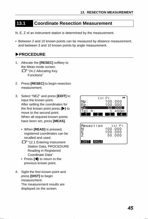
3. Select “NEZ” and press [EDIT] to input the known point. After setting the coordinates for the first known point press { } to move to the second point.When all required known points have been set, press [MEAS].
• When [READ] is pressed, registered coordinates can be recalled and used.
“12.1 Entering Instrument Station Data, PROCEDURE Reading in Registered Coordinate Data”
• Press { } to return to the previous known point.
4. Sight the first known point and press [DIST] to begin measurement.The measurement results are displayed on the screen.
13.1 Coordinate Resection Measurement
m
1 s t P t .
1 s t P t .
SET2120_13.fm 45 ページ 2001年12月7日 金曜日 午前11時34分
13. RESECTION MEASUREMENT
46
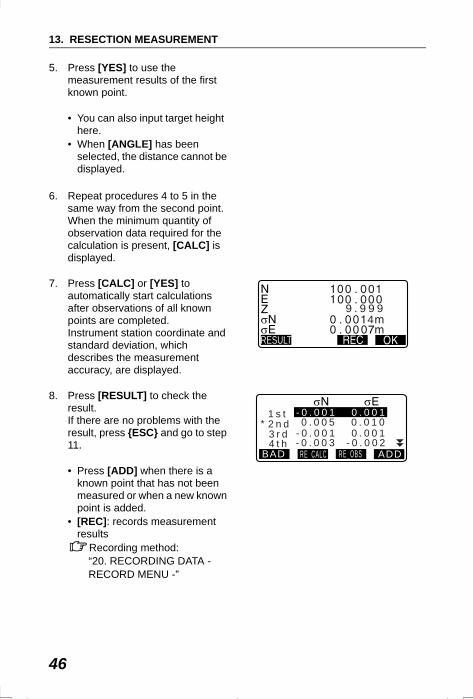
5. Press [YES] to use the measurement results of the first known point.
• You can also input target height here.
• When [ANGLE] has been selected, the distance cannot be displayed.
6. Repeat procedures 4 to 5 in the same way from the second point.When the minimum quantity of observation data required for the calculation is present, [CALC] is displayed.
7. Press [CALC] or [YES] to automatically start calculations after observations of all known points are completed.Instrument station coordinate and standard deviation, which describes the measurement accuracy, are displayed.
8. Press [RESULT] to check the result. If there are no problems with the result, press {ESC} and go to step 11.
• Press [ADD] when there is a known point that has not been measured or when a new known point is added.
• [REC]: records measurement results
Recording method: “20. RECORDING DATA - RECORD MENU -”
9 . 9 9 94
RESULT
1 s t 2 n d 3 r d
BAD RE_CALC RE_OBS ADD
- 0 . 0 0 1 0 . 0 0 1
- 0 . 0 0 1 0 . 0 0 1 0 . 0 0 5 0 . 0 1 0
4 t h - 0 . 0 0 3 - 0 . 0 0 2
*
SET2120_13.fm 46 ページ 2001年12月7日 金曜日 午前11時34分
47
13. RESECTION MEASUREMENT
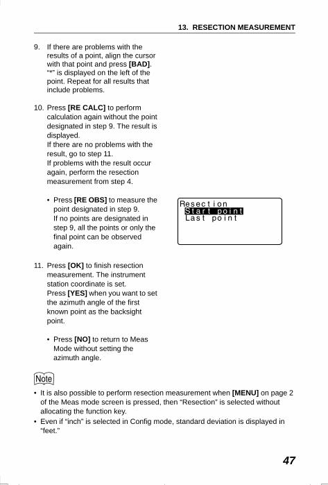
9. If there are problems with the results of a point, align the cursor with that point and press [BAD]. “*” is displayed on the left of the point. Repeat for all results that include problems.
10. Press [RE CALC] to perform calculation again without the point designated in step 9. The result is displayed.If there are no problems with the result, go to step 11.If problems with the result occur again, perform the resection measurement from step 4.
• Press [RE OBS] to measure the point designated in step 9. If no points are designated in step 9, all the points or only the final point can be observed again.
11. Press [OK] to finish resection measurement. The instrument station coordinate is set.Press [YES] when you want to set the azimuth angle of the first known point as the backsight point.
• Press [NO] to return to Meas Mode without setting the azimuth angle.
• It is also possible to perform resection measurement when [MENU] on page 2 of the Meas mode screen is pressed, then “Resection” is selected without allocating the function key.
• Even if “inch” is selected in Config mode, standard deviation is displayed in “feet.”
SET2120_13.fm 47 ページ 2001年12月7日 金曜日 午前11時34分
13. RESECTION MEASUREMENT
48
Only Z (height) of an instrument station is determined by the measurement.
• Known points must be measured by distance measurement only.• Between 1 and 10 known points can be measured.
PROCEDURE
1. Press [RESEC] to begin resection measurement.
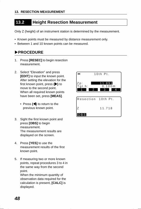
2. Select “Elevation” and press [EDIT] to input the known point. After setting the elevation for the first known point, press { } to move to the second point.When all required known points have been set, press [MEAS].
• Press { } to return to the previous known point.
3. Sight the first known point and press [OBS] to begin measurement.The measurement results are displayed on the screen.
4. Press [YES] to use the measurement results of the first known point.
5. If measuring two or more known points, repeat procedures 3 to 4 in the same way from the second point.When the minimum quantity of observation data required for the calculation is present, [CALC] is displayed.
13.2 Height Resection Measurement
R e s e c t i o n 1 0 t h P t .
Z 1 1 . 7 1 8
O B S
1 0 t h P t .
Z p :T g t . h : 0 . 1 0 0 m
1 1 . 8 9 1
1 2 3 4
SET2120_13.fm 48 ページ 2001年12月7日 金曜日 午前11時34分
49
13. RESECTION MEASUREMENT
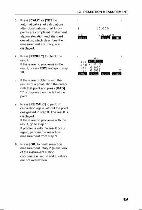
6. Press [CALC] or [YES] to automatically start calculations after observations of all known points are completed. Instrument station elevation and standard deviation, which describes the measurement accuracy, are displayed.
7. Press [RESULT] to check the result.If there are no problems in the result, press {ESC} and go to step 10.
8. If there are problems with the results of a point, align the cursor with that point and press [BAD]. “*” is displayed on the left of the point.
9. Press [RE CALC] to perform calculation again without the point designated in step 8. The result is displayed.If there are no problems with the result, go to step 10.If problems with the result occur again, perform the resection measurement from step 3.
10. Press [OK] to finish resection measurement. Only Z (elevation) of the instrument station coordinate is set. N and E values are not overwritten.
Z
Z R E S U LT REC
1 0 . 0 0 0
0 . 0 0 2 2 mOK
1 s t 2 n d 3 r d
BAD RE_CALC RE_OBS ADD
0 . 0 0 0
- 0 . 0 0 3- 0 . 0 0 3
4 t h 0 . 0 0 2
Z
SET2120_13.fm 49 ページ 2001年12月7日 金曜日 午前11時34分
13. RESECTION MEASUREMENT
50
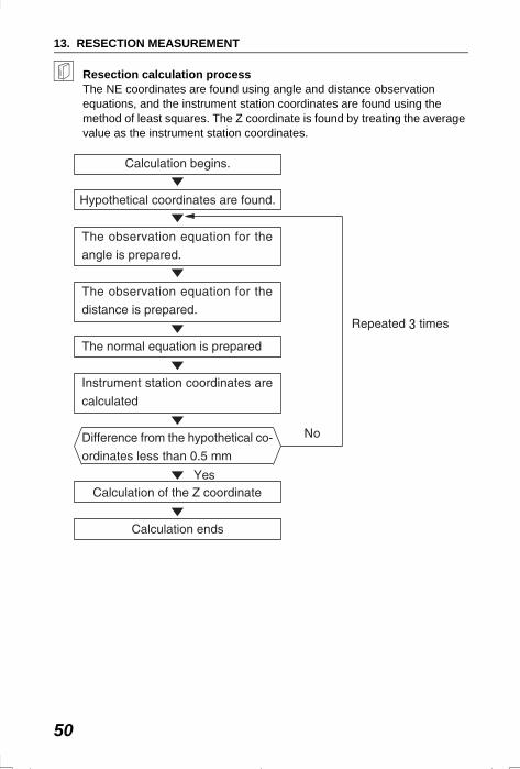
Resection calculation processThe NE coordinates are found using angle and distance observation equations, and the instrument station coordinates are found using the method of least squares. The Z coordinate is found by treating the average value as the instrument station coordinates.
SET2120_13.fm 50 ページ 2001年12月7日 金曜日 午前11時34分
51
13. RESECTION MEASUREMENT
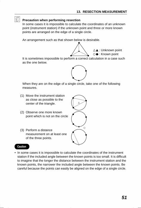
Precaution when performing resectionIn some cases it is impossible to calculate the coordinates of an unknown point (instrument station) if the unknown point and three or more known points are arranged on the edge of a single circle.
An arrangement such as that shown below is desirable.
It is sometimes impossible to perform a correct calculation in a case such as the one below.
When they are on the edge of a single circle, take one of the following measures.
(1) Move the instrument station as close as possible to the center of the triangle.
(2) Observe one more known point which is not on the circle
(3) Perform a distance measurement on at least one of the three points.
• In some cases it is impossible to calculate the coordinates of the instrument station if the included angle between the known points is too small. It is difficult to imagine that the longer the distance between the instrument station and the known points, the narrower the included angle between the known points. Be careful because the points can easily be aligned on the edge of a single circle.
: Unknown point : Known point
SET2120_13.fm 51 ページ 2001年12月7日 金曜日 午前11時34分
52
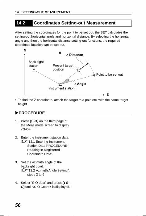
14.SETTING-OUT MEASUREMENTSetting-out measurement is used to set out the required point. The difference between the previously input data to the instrument (the setting-out data) and the measured value can be displayed by measuring the horizontal angle, distance or coordinates of the sighted point.
The horizontal angle difference and distance difference are calculated and displayed using the following formulae.
• Setting out data can be input in various modes: slope distance, horizontal distance, height difference, coordinates and REM measurement.
• In slope distance, horizontal distance, height difference, and coordinate mode, registered coordinates can be recalled and used as setting-out coordinates. In slope distance, horizontal distance and height difference, S/H/V distances are calculated from the read in setting-out coordinate, instrument station data, instrument height, and target height.
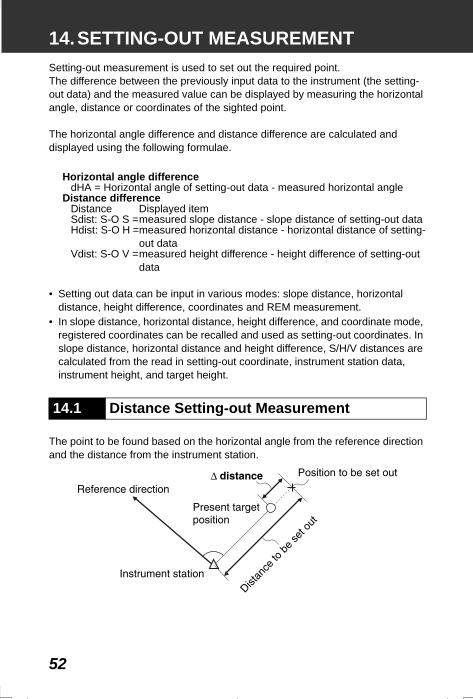
The point to be found based on the horizontal angle from the reference direction and the distance from the instrument station.
Horizontal angle differencedHA = Horizontal angle of setting-out data - measured horizontal angle
Distance differenceDistance Displayed itemSdist: S-O S =measured slope distance - slope distance of setting-out dataHdist: S-O H =measured horizontal distance - horizontal distance of setting-
out dataVdist: S-O V =measured height difference - height difference of setting-out
data
14.1 Distance Setting-out Measurement
SET2120_14.fm 52 ページ 2001年12月7日 金曜日 午前11時34分
53
14. SETTING-OUT MEASUREMENT
PROCEDURE
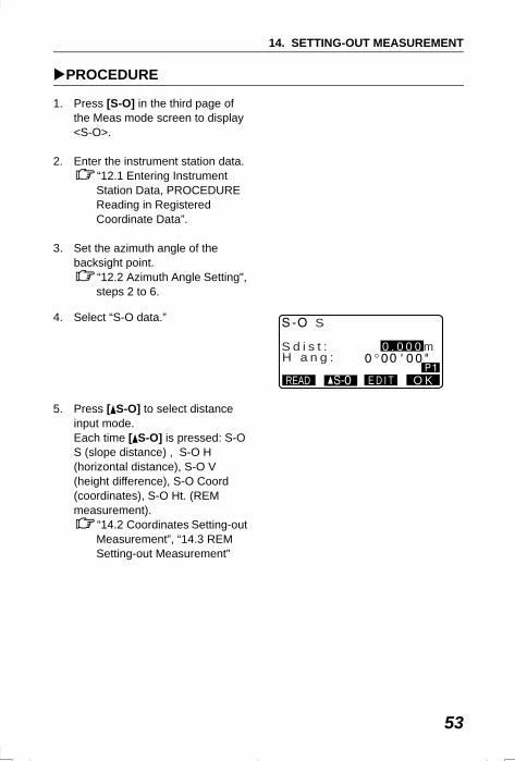
1. Press [S-O] in the third page of the Meas mode screen to display <S-O>.
2. Enter the instrument station data.“12.1 Entering Instrument Station Data, PROCEDURE Reading in Registered Coordinate Data”.
3. Set the azimuth angle of the backsight point.
“12.2 Azimuth Angle Setting", steps 2 to 6.
4. Select “S-O data.”
5. Press [ S-O] to select distance input mode.Each time [ S-O] is pressed: S-O S (slope distance) , S-O H (horizontal distance), S-O V (height difference), S-O Coord (coordinates), S-O Ht. (REM measurement).
“14.2 Coordinates Setting-out Measurement”, “14.3 REM Setting-out Measurement”
READ
S d i s t :H a n g :
S
0 . 0 0 0 m
E D I T O K
SET310_14.fm 53 ページ 2002年8月19日 月曜日 午後2時1分
14. SETTING-OUT MEASUREMENT
54
• When [READ] is pressed, registered coordinates can be recalled and used. Distance and angle are calculated using the coordinate value.
“12.1 Entering Instrument Station Data, PROCEDURE Reading in Registered Coordinate Data”
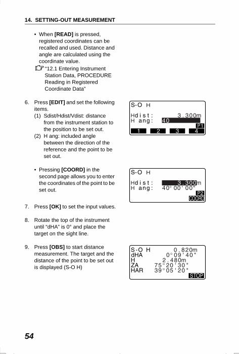
6. Press [EDIT] and set the following items.(1) Sdist/Hdist/Vdist: distance
from the instrument station to the position to be set out.
(2) H ang: included angle between the direction of the reference and the point to be set out.
• Pressing [COORD] in the second page allows you to enter the coordinates of the point to be set out.
7. Press [OK] to set the input values.
8. Rotate the top of the instrument until “dHA” is 0° and place the target on the sight line.
9. Press [OBS] to start distance measurement. The target and the distance of the point to be set out is displayed (S-O H)
HH
H
HH
H
SET310_14.fm 54 ページ 2001年12月11日 火曜日 午前9時7分
55
14. SETTING-OUT MEASUREMENT
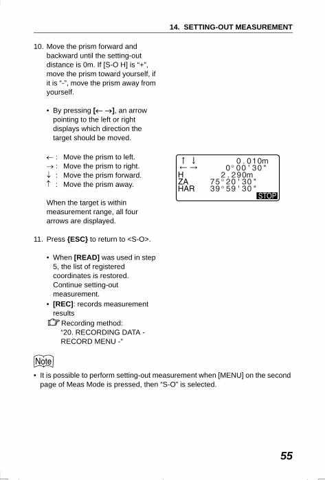
10. Move the prism forward and backward until the setting-out distance is 0m. If [S-O H] is “+”, move the prism toward yourself, if it is “-”, move the prism away from yourself.
• By pressing [← →], an arrow pointing to the left or right displays which direction the target should be moved.
← : Move the prism to left.→ : Move the prism to right.↓ : Move the prism forward.↑ : Move the prism away.
When the target is within measurement range, all four arrows are displayed.
11. Press {ESC} to return to <S-O>.
• When [READ] was used in step 5, the list of registered coordinates is restored. Continue setting-out measurement.
• [REC]: records measurement results
Recording method: “20. RECORDING DATA - RECORD MENU -”
• It is possible to perform setting-out measurement when [MENU] on the second page of Meas Mode is pressed, then “S-O” is selected.
SET2120_14.fm 55 ページ 2001年12月7日 金曜日 午前11時34分
14. SETTING-OUT MEASUREMENT
56
After setting the coordinates for the point to be set out, the SET calculates the setting-out horizontal angle and horizontal distance. By selecting the horizontal angle and then the horizontal distance setting-out functions, the required coordinate location can be set out.
• To find the Z coordinate, attach the target to a pole etc. with the same target height.
PROCEDURE
1. Press [S-O] on the third page of the Meas mode screen to display <S-O>.
2. Enter the instrument station data.“12.1 Entering Instrument Station Data PROCEDURE Reading in Registered Coordinate Data”.
3. Set the azimuth angle of the backsight point.
“12.2 Azimuth Angle Setting”, steps 2 to 6
4. Select “S-O data” and press [ S-O] until <S-O Coord> is displayed.
14.2 Coordinates Setting-out Measurement
SET310_14.fm 56 ページ 2002年8月19日 月曜日 午後2時6分
57
14. SETTING-OUT MEASUREMENT
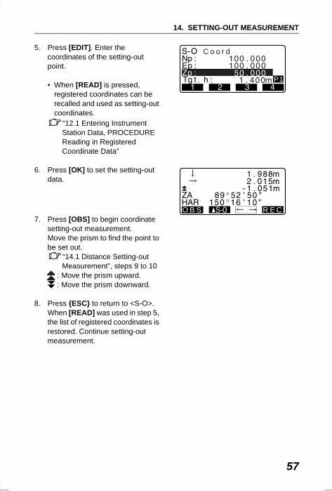
5. Press [EDIT]. Enter the coordinates of the setting-out point.
• When [READ] is pressed, registered coordinates can be recalled and used as setting-out coordinates.
“12.1 Entering Instrument Station Data, PROCEDURE Reading in Registered Coordinate Data”
6. Press [OK] to set the setting-out data.
7. Press [OBS] to begin coordinate setting-out measurement. Move the prism to find the point to be set out.
“14.1 Distance Setting-out Measurement”, steps 9 to 10
: Move the prism upward. : Move the prism downward.
8. Press {ESC} to return to <S-O>.When [READ] was used in step 5, the list of registered coordinates is restored. Continue setting-out measurement.
C o o r d
P1
O B S R E C
SET310_14.fm 57 ページ 2002年8月19日 月曜日 午後2時4分
14. SETTING-OUT MEASUREMENT
58
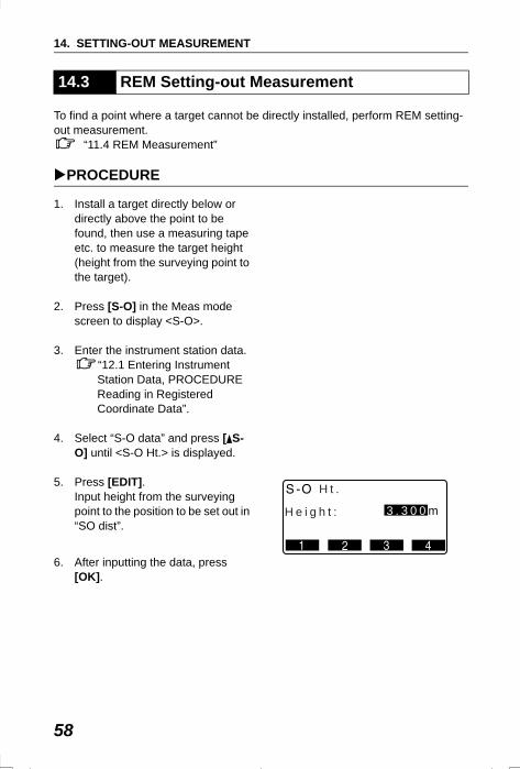
To find a point where a target cannot be directly installed, perform REM setting-out measurement.
“11.4 REM Measurement”
PROCEDURE
1. Install a target directly below or directly above the point to be found, then use a measuring tape etc. to measure the target height (height from the surveying point to the target).
2. Press [S-O] in the Meas mode screen to display <S-O>.
3. Enter the instrument station data.“12.1 Entering Instrument Station Data, PROCEDURE Reading in Registered Coordinate Data”.
4. Select “S-O data” and press [ S-O] until <S-O Ht.> is displayed.
5. Press [EDIT]. Input height from the surveying point to the position to be set out in “SO dist”.
6. After inputting the data, press [OK].
14.3 REM Setting-out Measurement
3 . 3 0 0 m
H t .
H e i g h t :
SET2120_14.fm 58 ページ 2001年12月7日 金曜日 午前11時34分
59
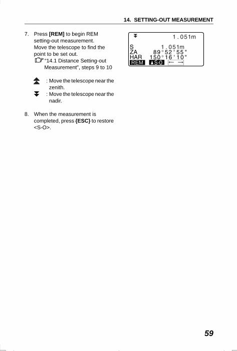
14. SETTING-OUT MEASUREMENT
7. Press [REM] to begin REM setting-out measurement.Move the telescope to find the point to be set out.
“14.1 Distance Setting-out Measurement”, steps 9 to 10
: Move the telescope near the zenith.
: Move the telescope near the nadir.
8. When the measurement is completed, press {ESC} to restore <S-O>.
REM
SET310_14.fm 59 ページ 2002年8月19日 月曜日 午後5時13分
60
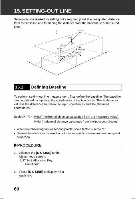
15.SETTING-OUT LINESetting-out line is used for setting out a required point at a designated distance from the baseline and for finding the distance from the baseline to a measured point.
To perform setting-out line measurement, first, define the baseline. The baseline can be defined by inputting the coordinates of the two points. The scale factor value is the difference between the input coordinates and the observed coordinates.
• When not observing first or second points, scale factor is set to “1”.• Defined baseline can be used in both setting-out line measurement and point
projection.
PROCEDURE
1. Allocate the [S-O LINE] to the Meas mode screen.
“24.2 Allocating Key Functions”
2. Press [S-O LINE] to display <Set-out line>.
15.1 Defining Baseline
Scale (X, Y) = Hdist’ (horizontal distance calculated from the measured value)Hdist (horizontal distance calculated from the input coordinates)
2nd Pt.
Cut
FillGrade
Z
EBaseline
Offset
LengthAzimuth
N
1st Pt.
SET2120_15.fm 60 ページ 2001年12月7日 金曜日 午前11時35分
61
15. SETTING-OUT LINE
3. Enter the instrument station data.“12.1 Entering Instrument Station Data, PROCEDURE Reading in Registered Coordinate Data”.
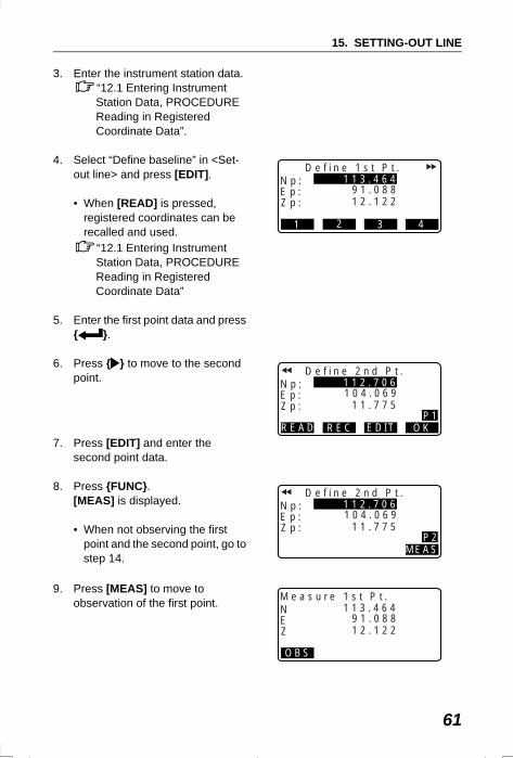
4. Select “Define baseline” in <Set-out line> and press [EDIT].
• When [READ] is pressed, registered coordinates can be recalled and used.
“12.1 Entering Instrument Station Data, PROCEDURE Reading in Registered Coordinate Data”
5. Enter the first point data and press { }.
6. Press { } to move to the second point.
7. Press [EDIT] and enter the second point data.
8. Press {FUNC}. [MEAS] is displayed.
• When not observing the first point and the second point, go to step 14.
9. Press [MEAS] to move to observation of the first point.
D e f i n e 1 s t P t .N p :E p :Z p : 1 2 . 1 2 2
1 1 3 . 4 6 49 1 . 0 8 8
1 2 3 4
D e f i n e 2 n d P t .N p :E p :Z p :
READ REC EDIT OK
1 1 . 7 7 5
1 1 2 . 7 0 61 0 4 . 0 6 9
P1
D e f i n e 2 n d P t .N p :E p :Z p :
MEAS
1 1 . 7 7 5
1 1 2 . 7 0 61 0 4 . 0 6 9
P2
M e a s u r e 1 s t P t .NEZ
OBS
1 2 . 1 2 2
1 1 3 . 4 6 49 1 . 0 8 8
SET2120_15.fm 61 ページ 2001年12月7日 金曜日 午前11時35分
15. SETTING-OUT LINE
62
10. Sight the first point and press [OBS].The measurement results are displayed on the screen.
• Press [STOP] to stop the measurement.
• You can input target height here.
11. Press [YES] to use the measurement results of the first point.
• Press [NO] to observe the first point again.
12. Sight the second point and press [OBS].
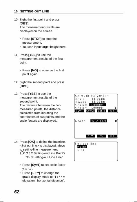
13. Press [YES] to use the measurement results of the second point.The distance between the two measured points, the distance calculated from inputting the coordinates of two points and the scale factors are displayed.
14. Press [OK] to define the baseline. <Set-out line> is displayed. Move to setting-line measurement.
“15.2 Setting-out Line Point”/“15.3 Setting-out Line Line”
• Press [Sy=1] to set scale factor y to “1”.
• Press [1 : **] to change the grade display mode to “1 : * * = elevation : horizontal distance”.
G r a d e
1:** % OK
% - 2 . 6 6 9G r a d e
1:** % OK
% - 2 . 6 6 9
A z i m u t h 9 3 ˚ 2 0 ′ 3 1 ″H c a l cH m e a sS c a l e X
Sy=1 Sy=Sx EDIT OK
1.000091
13.003m13.004m
S c a l e Y 1.000091
S e t - o u t l i n eP o i n tL i n e
SET2120_15.fm 62 ページ 2001年12月7日 金曜日 午前11時35分
63
15. SETTING-OUT LINE
• It is also possible to perform setting-out line measurement when [MENU] on page 2 of the Meas mode screen is pressed, then “Set-out line” is selected without allocating the function key.
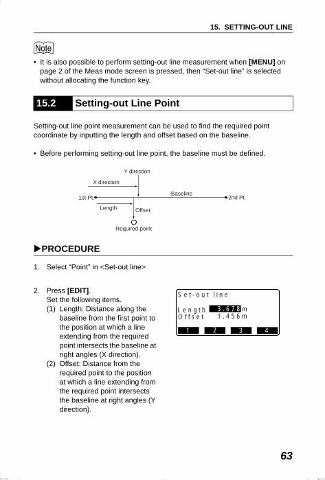
Setting-out line point measurement can be used to find the required point coordinate by inputting the length and offset based on the baseline.
• Before performing setting-out line point, the baseline must be defined.
PROCEDURE
1. Select “Point” in <Set-out line>
2. Press [EDIT]. Set the following items. (1) Length: Distance along the
baseline from the first point to the position at which a line extending from the required point intersects the baseline at right angles (X direction).
(2) Offset: Distance from the required point to the position at which a line extending from the required point intersects the baseline at right angles (Y direction).
15.2 Setting-out Line Point
Baseline1st Pt.
Length
X direction
Y direction
Offset
Required point
2nd Pt.
S e t - o u t l i n e
L e n g t hO f f s e t 1 . 4 5 6 m
3 . 6 7 8 m
1 2 3 4
SET2120_15.fm 63 ページ 2001年12月7日 金曜日 午前11時35分
15. SETTING-OUT LINE
64
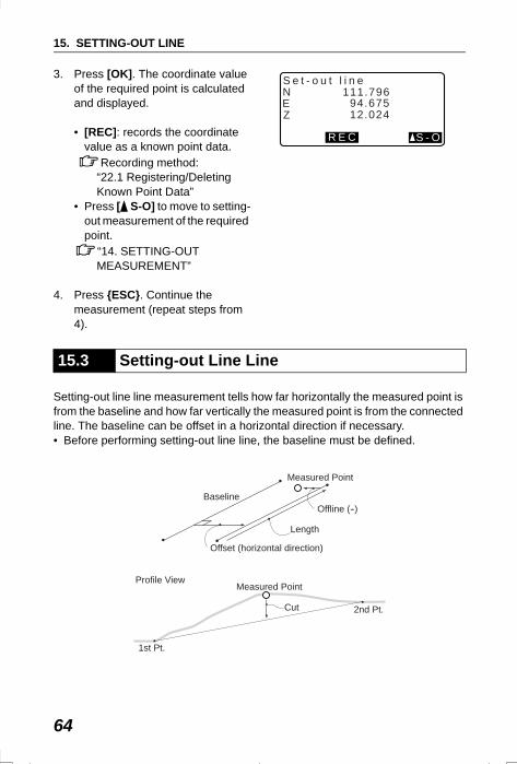
3. Press [OK]. The coordinate value of the required point is calculated and displayed.
• [REC]: records the coordinate value as a known point data.
Recording method: “22.1 Registering/Deleting Known Point Data”
• Press [ S-O] to move to setting-out measurement of the required point.
“14. SETTING-OUT MEASUREMENT”
4. Press {ESC}. Continue the measurement (repeat steps from 4).
Setting-out line line measurement tells how far horizontally the measured point is from the baseline and how far vertically the measured point is from the connected line. The baseline can be offset in a horizontal direction if necessary.• Before performing setting-out line line, the baseline must be defined.
15.3 Setting-out Line Line
S e t - o u t l i n e
12.02494.675
R E C S - O
NEZ
111.796
Baseline
Measured Point
Offset (horizontal direction)
Offline (--)
Length
1st Pt.
2nd Pt.
Measured Point
Cut
Profile View
SET2120_15.fm 64 ページ 2001年12月7日 金曜日 午前11時35分
65
15. SETTING-OUT LINE
PROCEDURE
1. Select “Line” in <Set-out line>.
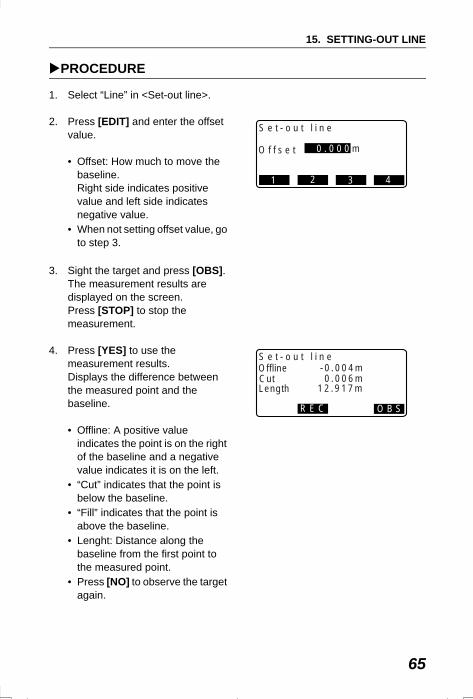
2. Press [EDIT] and enter the offset value.
• Offset: How much to move the baseline.Right side indicates positive value and left side indicates negative value.
• When not setting offset value, go to step 3.
3. Sight the target and press [OBS]. The measurement results are displayed on the screen.Press [STOP] to stop the measurement.
4. Press [YES] to use the measurement results. Displays the difference between the measured point and the baseline.
• Offline: A positive value indicates the point is on the right of the baseline and a negative value indicates it is on the left.
• “Cut” indicates that the point is below the baseline.
• “Fill” indicates that the point is above the baseline.
• Lenght: Distance along the baseline from the first point to the measured point.
• Press [NO] to observe the target again.
S e t - o u t l i n e
O f f s e t 0 . 0 0 0 m
1 2 3 4
S e t - o u t l i n e
0.006m-0.004m
R E C O B S
OfflineCut
12.917mLength
SET2120_15.fm 65 ページ 2001年12月7日 金曜日 午前11時35分
15. SETTING-OUT LINE
66
5. Sight the next target and press [OBS] to continue the measurement.
• Press [REC]: records measurement results.
Recording method: “20. RECORDING DATA - RECORD MENU -”
SET2120_15.fm 66 ページ 2001年12月7日 金曜日 午前11時35分
67
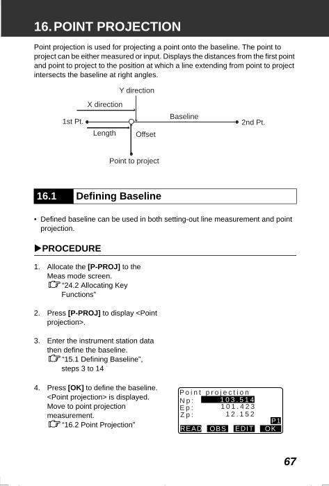
16.POINT PROJECTIONPoint projection is used for projecting a point onto the baseline. The point to project can be either measured or input. Displays the distances from the first point and point to project to the position at which a line extending from point to project intersects the baseline at right angles.
• Defined baseline can be used in both setting-out line measurement and point projection.
PROCEDURE
1. Allocate the [P-PROJ] to the Meas mode screen.
“24.2 Allocating Key Functions”
2. Press [P-PROJ] to display <Point projection>.
3. Enter the instrument station data then define the baseline.
“15.1 Defining Baseline”, steps 3 to 14
4. Press [OK] to define the baseline. <Point projection> is displayed. Move to point projection measurement.
“16.2 Point Projection”
16.1 Defining Baseline
Y direction
X direction
1st Pt.Length Offset
Point to project
Baseline2nd Pt.
P o i n t p r o j e c t i o nN p :E p :Z p :
READ OBS EDIT OK
1 2 . 1 5 2
1 0 3 . 5 1 41 0 1 . 4 2 3
P1
SET310_16.fm 67 ページ 2002年8月19日 月曜日 午後5時49分
16. POINT PROJECTION
68
• It is also possible to perform setting-out line measurement when [MENU] on page 2 of the Meas mode screen is pressed, then “Point Projection” is selected without allocating the function key.
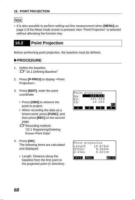
Before performing point projection, the baseline must be defined.
PROCEDURE
1. Define the baseline.“16.1 Defining Baseline”
2. Press [P-PROJ] to display <Point Projection>.
3. Press [EDIT], enter the point coordinate.
• Press [OBS] to observe the point to project.
• When recording the data as a known point, press {FUNC}, and then press [REC] on the second page.
Recording method: “22.1 Registering/Deleting Known Point Data”
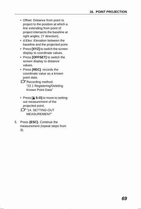
4. Press [OK]. The following items are calculated and displayed.
• Length: Distance along the baseline from the first point to the projected point (X direction).
16.2 Point Projection
P o i n t p r o j e c t i o nN p :E p :Z p :
1 2 3 4
1 2 . 1 5 2
1 0 3 . 5 1 41 0 1 . 4 2 3
P1
P o i n t p r o j e c t i o nL e n g t hO f f s e td . E l e v
XYZ REC S-O
0 . 3 2 1 m
1 0 . 8 7 9 m9 . 3 4 0 m
SET2120_16.fm 68 ページ 2001年12月7日 金曜日 午後1時9分
69
16. POINT PROJECTION
• Offset: Distance from point to project to the position at which a line extending from point of project intersects the baseline at right angles. (Y direction).
• d.Elev: Elevation between the baseline and the projected point.
• Press [XYZ] to switch the screen display to coordinate values.
• Press [OFFSET] to switch the screen display to distance values.
• Press [REC]: records the coordinate value as a known point data.
Recording method: “22.1 Registering/Deleting Known Point Data”
• Press [ S-O] to move to setting-out measurement of the projected point.
“14. SETTING-OUT MEASUREMENT”
5. Press {ESC}. Continue the measurement (repeat steps from 3).
SET2120_16.fm 69 ページ 2001年12月7日 金曜日 午後1時9分
70
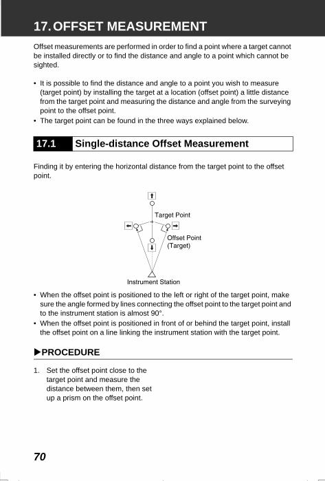
17.OFFSET MEASUREMENTOffset measurements are performed in order to find a point where a target cannot be installed directly or to find the distance and angle to a point which cannot be sighted.
• It is possible to find the distance and angle to a point you wish to measure (target point) by installing the target at a location (offset point) a little distance from the target point and measuring the distance and angle from the surveying point to the offset point.
• The target point can be found in the three ways explained below.
Finding it by entering the horizontal distance from the target point to the offset point.
• When the offset point is positioned to the left or right of the target point, make sure the angle formed by lines connecting the offset point to the target point and to the instrument station is almost 90°.
• When the offset point is positioned in front of or behind the target point, install the offset point on a line linking the instrument station with the target point.
PROCEDURE
1. Set the offset point close to the target point and measure the distance between them, then set up a prism on the offset point.
17.1 Single-distance Offset Measurement
SET310_17.fm 70 ページ 2001年12月11日 火曜日 午前9時10分
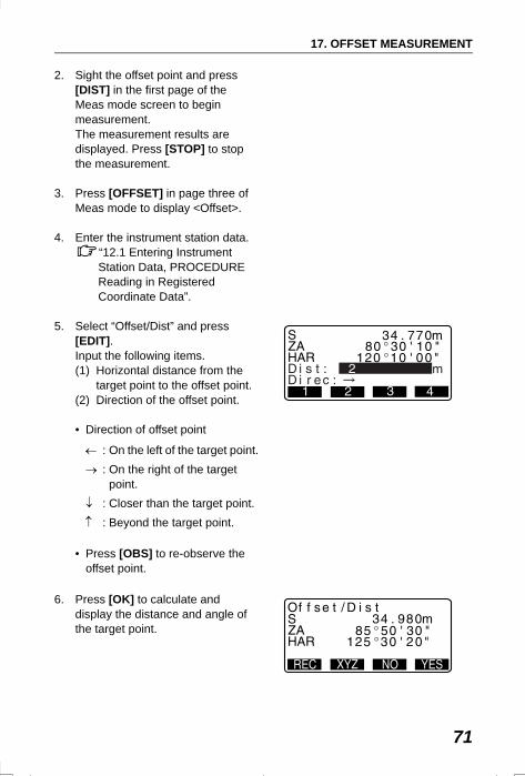
71
17. OFFSET MEASUREMENT
2. Sight the offset point and press [DIST] in the first page of the Meas mode screen to begin measurement. The measurement results are displayed. Press [STOP] to stop the measurement.
3. Press [OFFSET] in page three of Meas mode to display <Offset>.
4. Enter the instrument station data.“12.1 Entering Instrument Station Data, PROCEDURE Reading in Registered Coordinate Data”.
5. Select “Offset/Dist” and press [EDIT].Input the following items. (1) Horizontal distance from the
target point to the offset point.(2) Direction of the offset point.
• Direction of offset point
• Press [OBS] to re-observe the offset point.
6. Press [OK] to calculate and display the distance and angle of the target point.
← : On the left of the target point.→ : On the right of the target
point.↓ : Closer than the target point.↑ : Beyond the target point.
22
SET310_17.fm 71 ページ 2001年12月11日 火曜日 午前9時10分
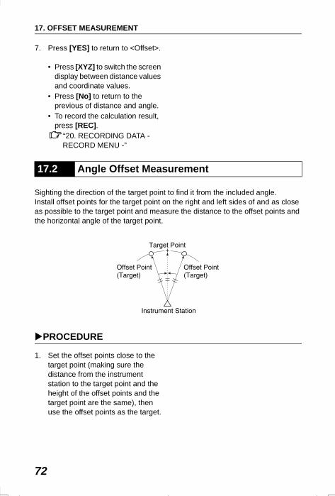
17. OFFSET MEASUREMENT
72
7. Press [YES] to return to <Offset>.
• Press [XYZ] to switch the screen display between distance values and coordinate values.
• Press [No] to return to the previous of distance and angle.
• To record the calculation result, press [REC].
“20. RECORDING DATA - RECORD MENU -”
Sighting the direction of the target point to find it from the included angle.Install offset points for the target point on the right and left sides of and as close as possible to the target point and measure the distance to the offset points and the horizontal angle of the target point.
PROCEDURE
1. Set the offset points close to the target point (making sure the distance from the instrument station to the target point and the height of the offset points and the target point are the same), then use the offset points as the target.
17.2 Angle Offset Measurement
SET310_17.fm 72 ページ 2001年12月11日 火曜日 午前9時10分
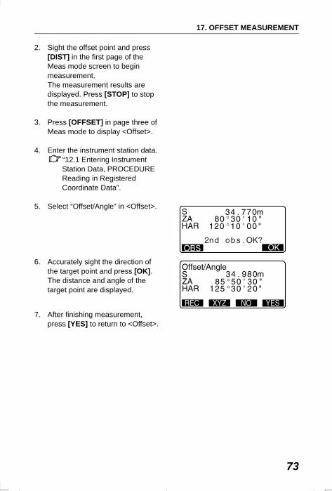
73
17. OFFSET MEASUREMENT
2. Sight the offset point and press [DIST] in the first page of the Meas mode screen to begin measurement. The measurement results are displayed. Press [STOP] to stop the measurement.
3. Press [OFFSET] in page three of Meas mode to display <Offset>.
4. Enter the instrument station data.“12.1 Entering Instrument Station Data, PROCEDURE Reading in Registered Coordinate Data”.
5. Select “Offset/Angle” in <Offset>.
6. Accurately sight the direction of the target point and press [OK].The distance and angle of the target point are displayed.
7. After finishing measurement, press [YES] to return to <Offset>.
SET310_17.fm 73 ページ 2001年12月11日 火曜日 午前9時10分
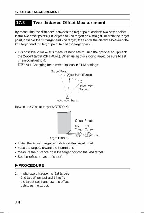
17. OFFSET MEASUREMENT
74
By measuring the distances between the target point and the two offset points.Install two offset points (1st target and 2nd target) on a straight line from the target point, observe the 1st target and 2nd target, then enter the distance between the 2nd target and the target point to find the target point.
• It is possible to make this measurement easily using the optional equipment: the 2-point target (2RT500-K). When using this 2-point target, be sure to set prism constant to 0.
“24.1 Changing Instrument Options EDM settings”
How to use 2-point target (2RT500-K)
• Install the 2-point target with its tip at the target point.• Face the targets toward the instrument.• Measure the distance from the target point to the 2nd target.• Set the reflector type to “sheet”
PROCEDURE
1. Install two offset points (1st target, 2nd target) on a straight line from the target point and use the offset points as the target.
17.3 Two-distance Offset Measurement
SET310_17.fm 74 ページ 2002年2月13日 水曜日 午後2時54分
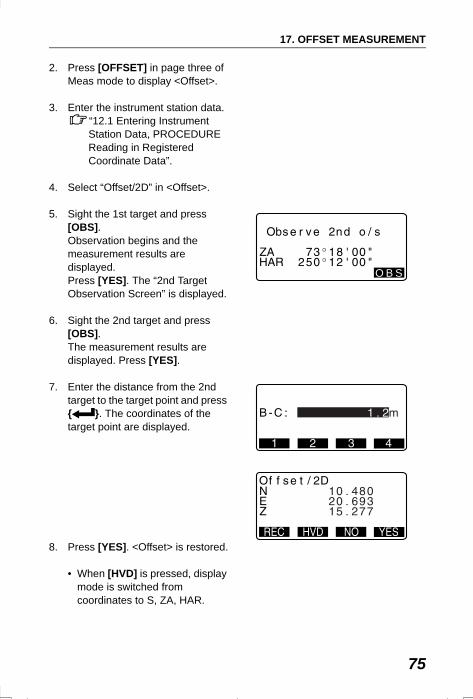
75
17. OFFSET MEASUREMENT
2. Press [OFFSET] in page three of Meas mode to display <Offset>.
3. Enter the instrument station data.“12.1 Entering Instrument Station Data, PROCEDURE Reading in Registered Coordinate Data”.
4. Select “Offset/2D” in <Offset>.
5. Sight the 1st target and press [OBS]. Observation begins and the measurement results are displayed.Press [YES]. The “2nd Target Observation Screen” is displayed.
6. Sight the 2nd target and press [OBS]. The measurement results are displayed. Press [YES].
7. Enter the distance from the 2nd target to the target point and press { }. The coordinates of the target point are displayed.
8. Press [YES]. <Offset> is restored.
• When [HVD] is pressed, display mode is switched from coordinates to S, ZA, HAR.
O B S
SET310_17.fm 75 ページ 2001年12月11日 火曜日 午前9時10分
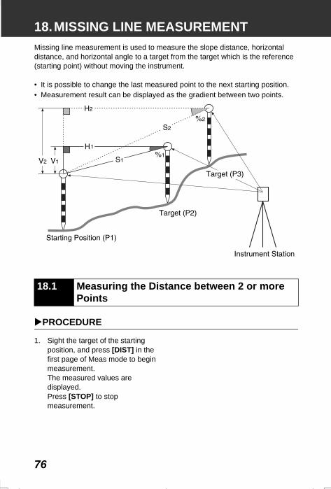
76
18.MISSING LINE MEASUREMENTMissing line measurement is used to measure the slope distance, horizontal distance, and horizontal angle to a target from the target which is the reference (starting point) without moving the instrument.
• It is possible to change the last measured point to the next starting position.• Measurement result can be displayed as the gradient between two points.
PROCEDURE
1. Sight the target of the starting position, and press [DIST] in the first page of Meas mode to begin measurement. The measured values are displayed. Press [STOP] to stop measurement.
18.1 Measuring the Distance between 2 or more Points
SET2120_18.fm 76 ページ 2001年12月7日 金曜日 午後1時2分
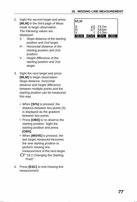
77
18. MISSING LINE MEASUREMENT
2. Sight the second target and press [MLM] in the third page of Meas mode to begin observation.The following values are displayed:S : Slope distance of the starting
position and 2nd target.H : Horizontal distance of the
starting position and 2nd position.
V : Height difference of the starting position and 2nd target.
3. Sight the next target and press [MLM] to begin observation. Slope distance, horizontal distance and height difference between multiple points and the starting position can be measured this way.
• When [S/%] is pressed, the distance between two points (S) is displayed as the gradient between two points.
• Press [OBS] to re-observe the starting position. Sight the starting position and press [OBS].
• When [MOVE] is pressed, the last target measured becomes the new starting position to perform missing line measurement of the next target.
“18.2 Changing the Starting Point”
4. Press {ESC} to end missing line measurement.
SET2120_18.fm 77 ページ 2001年12月7日 金曜日 午後1時2分
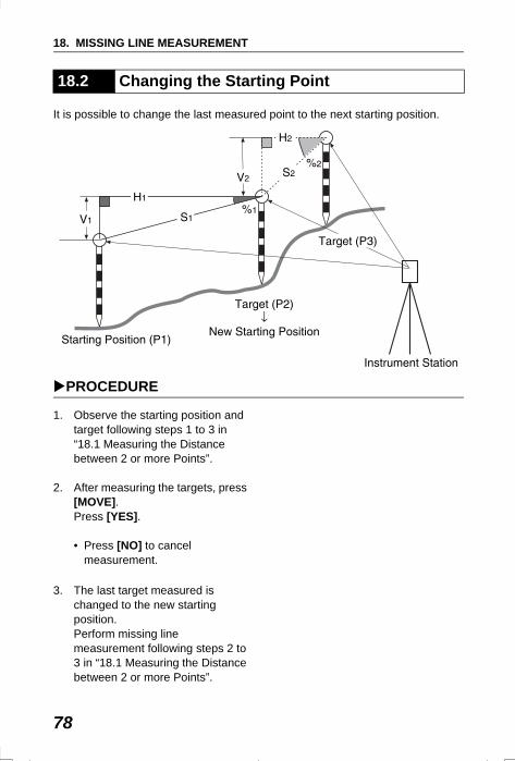
18. MISSING LINE MEASUREMENT
78
It is possible to change the last measured point to the next starting position.
PROCEDURE
1. Observe the starting position and target following steps 1 to 3 in “18.1 Measuring the Distance between 2 or more Points”.
2. After measuring the targets, press [MOVE]. Press [YES].
• Press [NO] to cancel measurement.
3. The last target measured is changed to the new starting position. Perform missing line measurement following steps 2 to 3 in “18.1 Measuring the Distance between 2 or more Points”.
18.2 Changing the Starting Point
SET310_18.fm 78 ページ 2002年6月25日 火曜日 午前10時43分
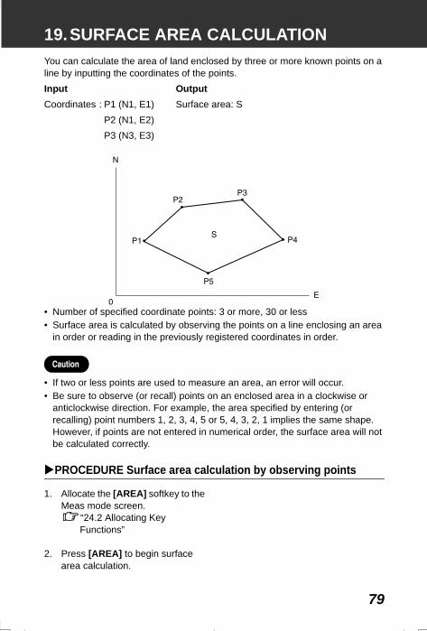
79
19.SURFACE AREA CALCULATIONYou can calculate the area of land enclosed by three or more known points on a line by inputting the coordinates of the points.
• Number of specified coordinate points: 3 or more, 30 or less• Surface area is calculated by observing the points on a line enclosing an area
in order or reading in the previously registered coordinates in order.
• If two or less points are used to measure an area, an error will occur.• Be sure to observe (or recall) points on an enclosed area in a clockwise or
anticlockwise direction. For example, the area specified by entering (or recalling) point numbers 1, 2, 3, 4, 5 or 5, 4, 3, 2, 1 implies the same shape. However, if points are not entered in numerical order, the surface area will not be calculated correctly.
PROCEDURE Surface area calculation by observing points
1. Allocate the [AREA] softkey to the Meas mode screen.
“24.2 Allocating Key Functions”
2. Press [AREA] to begin surface area calculation.
Input OutputCoordinates : P1 (N1, E1) Surface area: S
P2 (N1, E2)P3 (N3, E3)
SET2120_19.fm 79 ページ 2001年12月7日 金曜日 午後1時2分
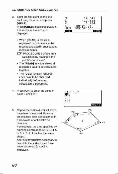
19. SURFACE AREA CALCULATION
80
3. Sight the first point on the line enclosing the area, and press [MEAS].Press [OBS] to begin observation. The measured values are displayed.
• When [READ] is pressed, registered coordinates can be recalled and used in subsequent measurements.
“PROCEDURE Surface area calculation by reading in the points’ coordinates”
• The [READ] function allows all registered data to be calculated together.
• The [OBS] function requires each point to be observed individually before area calculation is performed.
4. Press [OK] to enter the value of point 1 in “Pt.01”.
5. Repeat steps 3 to 4 until all points have been measured. Points on an enclosed area are observed in a clockwise or anticlockwise direction. For example, the area specified by entering point numbers 1, 2, 3, 4, 5 or 5, 4, 3, 2, 1 implies the same shape. After all known points necessary to calculate the surface area have been observed, [CALC] is displayed.
M E A S
SET2120_19.fm 80 ページ 2001年12月7日 金曜日 午後1時2分
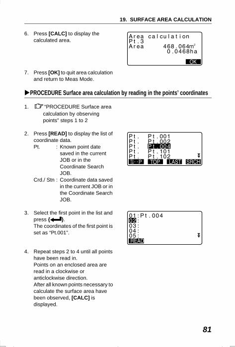
81
19. SURFACE AREA CALCULATION
6. Press [CALC] to display the calculated area.
7. Press [OK] to quit area calculation and return to Meas Mode.
PROCEDURE Surface area calculation by reading in the points’ coordinates
1. “PROCEDURE Surface area calculation by observing points” steps 1 to 2
2. Press [READ] to display the list of coordinate data. Pt. : Known point date
saved in the current JOB or in the Coordinate Search JOB.
Crd./ Stn : Coordinate data saved in the current JOB or in the Coordinate Search JOB.
3. Select the first point in the list and press { }. The coordinates of the first point is set as “Pt.001”.
4. Repeat steps 2 to 4 until all points have been read in. Points on an enclosed area are read in a clockwise or anticlockwise direction.After all known points necessary to calculate the surface area have been observed, [CALC] is displayed.
0 . 000
SET310_19.fm 81 ページ 2002年2月13日 水曜日 午後3時17分
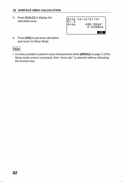
19. SURFACE AREA CALCULATION
82
5. Press [CALC] to display the calculated area.
6. Press [OK] to quit area calculation and return to Meas Mode.
• It is also possible to perform area measurement when [MENU] on page 2 of the Meas mode screen is pressed, then “Area calc” is selected without allocating the function key.
SET310_19.fm 82 ページ 2002年2月13日 水曜日 午後3時17分
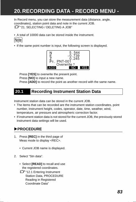
83
20.RECORDING DATA - RECORD MENU -In Record menu, you can store the measurement data (distance, angle, coordinates), station point data and note in the current JOB.
“21. SELECTING / DELETING A JOB”
• A total of 10000 data can be stored inside the instrument.
• If the same point number is input, the following screen is displayed.
Press [YES] to overwrite the present point.Press [NO] to input a new name.Press [ADD] to record the point as another record with the same name.
Instrument station data can be stored in the current JOB.• The items that can be recorded are the instrument station coordinates, point
number, instrument height, codes, operator, date, time, weather, wind, temperature, air pressure and atmospheric correction factor.
• If instrument station data is not stored for the current JOB, the previously stored instrument data settings will be used.
PROCEDURE
1. Press [REC] in the third page of Meas mode to display <REC>.
• Current JOB name is displayed.
2. Select “Stn data”.
• Select [READ] to recall and use the registered coordinates.
“12.1 Entering Instrument Station Data, PROCEDURE Reading in Registered Coordinate Data”
20.1 Recording Instrument Station Data
ADD
SET310_20.fm 83 ページ 2001年12月7日 金曜日 午後5時13分
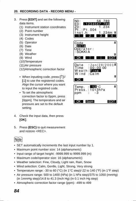
20. RECORDING DATA - RECORD MENU -
84
3. Press [EDIT] and set the following data items.(1) Instrument station coordinates(2) Point number(3) Instrument height(4) Codes(5) Operator(6) Date(7) Time(8) Weather(9) Wind(10)Temperature(11)Air pressure(12)Atmospheric correction factor
• When inputting code, press [↑] / [↓] to use the registered codes. Align the cursor where you want to input the registred code.
• To set the atmospheric correction factor to 0ppm, press [0ppm]. The temperature and air pressure are set to the default setting.
4. Check the input data, then press [OK].
5. Press {ESC} to quit measurement and restore <REC>.
• SET automatically increments the last input number by 1.• Maximum point number size: 14 (alphanumeric)• Input range of target height: -9999.999 to 9999.999 (m)• Maximum code/operator size: 16 (alphanumeric)• Weather selection: Fine, Cloudy, Light rain, Rain, Snow• Wind selection: Calm, Gentle, Light, Strong, Very strong• Temperature range: -30 to 60 (°C) (in 1°C step)/-22 to 140 (°F) (in 1°F step)• Air pressure range: 500 to 1400 (hPa) (in 1 hPa step)/375 to 1050 (mmHg)
(in 1mmHg step)/14.8 to 41.3 (inch Hg) (in 0.1 inch Hg step)• Atmospheric correction factor range (ppm): -499 to 499
9
J a n / 2 8 / 2 0 0 1
P
SET310_20.fm 84 ページ 2002年2月13日 水曜日 午後3時21分
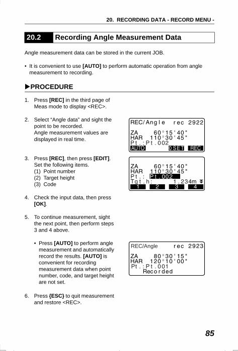
85
20. RECORDING DATA - RECORD MENU -
Angle measurement data can be stored in the current JOB.
• It is convenient to use [AUTO] to perform automatic operation from angle measurement to recording.
PROCEDURE
1. Press [REC] in the third page of Meas mode to display <REC>.
2. Select “Angle data” and sight the point to be recorded. Angle measurement values are displayed in real time.
3. Press [REC], then press [EDIT]. Set the following items.(1) Point number(2) Target height(3) Code
4. Check the input data, then press [OK].
5. To continue measurement, sight the next point, then perform steps 3 and 4 above.
• Press [AUTO] to perform angle measurement and automatically record the results. [AUTO] is convenient for recording measurement data when point number, code, and target height are not set.
6. Press {ESC} to quit measurement and restore <REC>.
20.2 Recording Angle Measurement Data
REC/Angle
SET310_20.fm 85 ページ 2001年12月7日 金曜日 午後5時13分
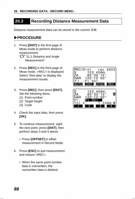
20. RECORDING DATA - RECORD MENU -
86
Distance measurement data can be stored in the current JOB.
PROCEDURE
1. Press [DIST] in the first page of Meas mode to perform distance measurement.
“11.1 Distance and Angle Measurement”
2. Press [REC] in the third page of Meas mode. <REC> is displayed.Select “Dist data” to display the measurement results.
3. Press [REC], then press [EDIT]. Set the following items.(1) Point number(2) Target height(3) Code
4. Check the input data, then press [OK].
5. To continue measurement, sight the next point, press [DIST], then perform steps 3 and 4 above.
• Press [OFFSET] to offset measurement in Record Mode.
6. Press {ESC} to quit measurement and restore <REC>.
• When the same point number data is overwritten, the overwritten data is deleted.
20.3 Recording Distance Measurement Data
SET310_20.fm 86 ページ 2001年12月7日 金曜日 午後5時13分
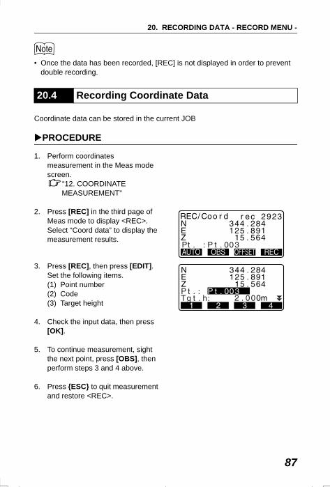
87
20. RECORDING DATA - RECORD MENU -
• Once the data has been recorded, [REC] is not displayed in order to prevent double recording.
Coordinate data can be stored in the current JOB
PROCEDURE
1. Perform coordinates measurement in the Meas mode screen.
“12. COORDINATE MEASUREMENT”
2. Press [REC] in the third page of Meas mode to display <REC>.Select “Coord data” to display the measurement results.
3. Press [REC], then press [EDIT]. Set the following items.(1) Point number(2) Code (3) Target height
4. Check the input data, then press [OK].
5. To continue measurement, sight the next point, press [OBS], then perform steps 3 and 4 above.
6. Press {ESC} to quit measurement and restore <REC>.
20.4 Recording Coordinate Data
SET310_20.fm 87 ページ 2001年12月7日 金曜日 午後5時13分
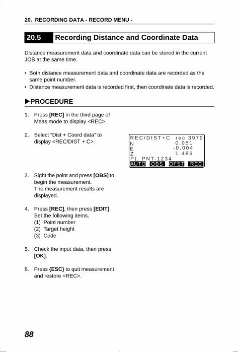
20. RECORDING DATA - RECORD MENU -
88
Distance measurement data and coordinate data can be stored in the current JOB at the same time.
• Both distance measurement data and coordinate data are recorded as the same point number.
• Distance measurement data is recorded first, then coordinate data is recorded.
PROCEDURE
1. Press [REC] in the third page of Meas mode to display <REC>.
2. Select “Dist + Coord data” to display <REC/DIST + C>.
3. Sight the point and press [OBS] to begin the measurement.The measurement results are displayed.
4. Press [REC], then press [EDIT]. Set the following items.(1) Point number(2) Target height(3) Code
5. Check the input data, then press [OK].
6. Press {ESC} to quit measurement and restore <REC>.
20.5 Recording Distance and Coordinate Data
NEZ
AUTO OBS OFST REC
1 . 4 8 6
0 . 0 5 1- 0 . 0 0 4
P t . P N T- 1 2 3 4
R E C / D I S T + C r e c 3 9 7 0
SET310_20.fm 88 ページ 2001年12月7日 金曜日 午後5時13分
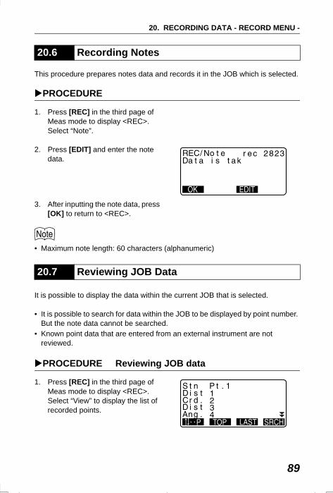
89
20. RECORDING DATA - RECORD MENU -
This procedure prepares notes data and records it in the JOB which is selected.
PROCEDURE
1. Press [REC] in the third page of Meas mode to display <REC>.Select “Note”.
2. Press [EDIT] and enter the note data.
3. After inputting the note data, press [OK] to return to <REC>.
• Maximum note length: 60 characters (alphanumeric)
It is possible to display the data within the current JOB that is selected.
• It is possible to search for data within the JOB to be displayed by point number. But the note data cannot be searched.
• Known point data that are entered from an external instrument are not reviewed.
PROCEDURE Reviewing JOB data
1. Press [REC] in the third page of Meas mode to display <REC>.Select “View” to display the list of recorded points.
20.6 Recording Notes
20.7 Reviewing JOB Data
0 . 000
SET310_20.fm 89 ページ 2001年12月7日 金曜日 午後5時13分
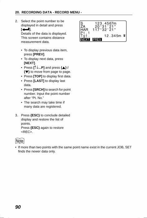
20. RECORDING DATA - RECORD MENU -
90
2. Select the point number to be displayed in detail and press [ ].Details of the data is displayed. This screen contains distance measurement data.
• To display previous data item, press [PREV].
• To display next data, press [NEXT].
• Press [↑↓...P] and press { } / { } to move from page to page.
• Press [TOP] to display first data.• Press [LAST] to display last
data.• Press [SRCH] to search for point
number. Input the point number after “Pt. No.”
• The search may take time if many data are registered.
3. Press {ESC} to conclude detailed display and restore the list of points. Press {ESC} again to restore <REC>.
• If more than two points with the same point name exist in the current JOB, SET finds the newer data only.
SET310_20.fm 90 ページ 2001年12月7日 金曜日 午後5時13分
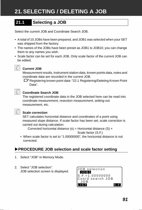
91
21.SELECTING / DELETING A JOB
Select the current JOB and Coordinate Search JOB.
• A total of 10 JOBs have been prepared, and JOB1 was selected when your SET was shipped from the factory.
• The names of the JOBs have been preset as JOB1 to JOB10; you can change them to any names you wish.
• Scale factor can be set for each JOB. Only scale factor of the current JOB can be edited.
Current JOBMeasurement results, instrument station data, known points data, notes and coordinate data are recorded in the current JOB.
Registering known point data: “22.1 Registering/Deleting Known Point Data”.
Coordinate Search JOBThe registered coordinate data in the JOB selected here can be read into coordinate measurement, resection measurement, setting-out measurement, etc.
Scale correctionSET calculates horizontal distance and coordinates of a point using measured slope distance. If scale factor has been set, scale correction is carried out during calculation.
Corrected horizontal distance (s) = Horizontal distance (S) × Scale factor (S.F.)
• When scale factor is set to “1.00000000”, the horizontal distance is not corrected.
PROCEDURE JOB selection and scale factor setting
1. Select “JOB” in Memory Mode.
2. Select “JOB selection”.JOB selection screen is displayed.
21.1 Selecting a JOB
J O B s e l e c t i o nJ O B 1
L I S T
:
C o o r d s e a r c h J O B: J O B
S . F. = 1 . 0 0 0 0 0 0 0 0
S . F.
SET2120_21.fm 91 ページ 2001年12月7日 金曜日 午後1時3分
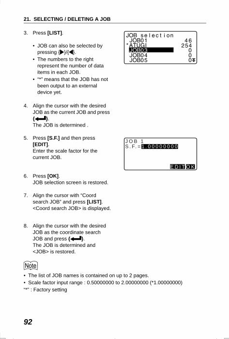
21. SELECTING / DELETING A JOB
92
3. Press [LIST].
• JOB can also be selected by pressing { }/{ }.
• The numbers to the right represent the number of data items in each JOB.
• “*” means that the JOB has not been output to an external device yet.
4. Align the cursor with the desired JOB as the current JOB and press { }.The JOB is determined .
5. Press [S.F.] and then press [EDIT].Enter the scale factor for the current JOB.
6. Press [OK].JOB selection screen is restored.
7. Align the cursor with “Coord search JOB” and press [LIST].<Coord search JOB> is displayed.
8. Align the cursor with the desired JOB as the coordinate search JOB and press { }.The JOB is determined and <JOB> is restored.
• The list of JOB names is contained on up to 2 pages.• Scale factor input range : 0.50000000 to 2.00000000 (*1.00000000)“*” : Factory setting
J O B 1
E D I T O K
S . F. = 1 . 0 0 0 0 0 0 0 0
SET2120_21.fm 92 ページ 2001年12月7日 金曜日 午後1時3分
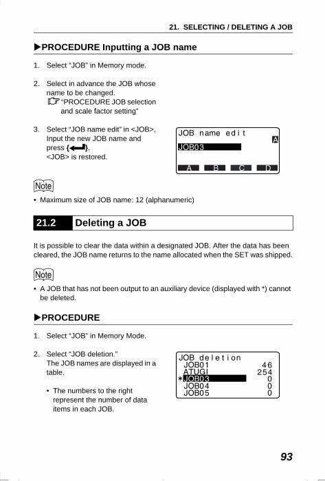
93
21. SELECTING / DELETING A JOB
PROCEDURE Inputting a JOB name
1. Select “JOB” in Memory mode.
2. Select in advance the JOB whose name to be changed.
“PROCEDURE JOB selection and scale factor setting”
3. Select “JOB name edit” in <JOB>, Input the new JOB name and press { }.<JOB> is restored.
• Maximum size of JOB name: 12 (alphanumeric)
It is possible to clear the data within a designated JOB. After the data has been cleared, the JOB name returns to the name allocated when the SET was shipped.
• A JOB that has not been output to an auxiliary device (displayed with *) cannot be deleted.
PROCEDURE
1. Select “JOB” in Memory Mode.
2. Select “JOB deletion.”The JOB names are displayed in a table.
• The numbers to the right represent the number of data items in each JOB.
21.2 Deleting a JOB
SET2120_21.fm 93 ページ 2001年12月7日 金曜日 午後1時3分
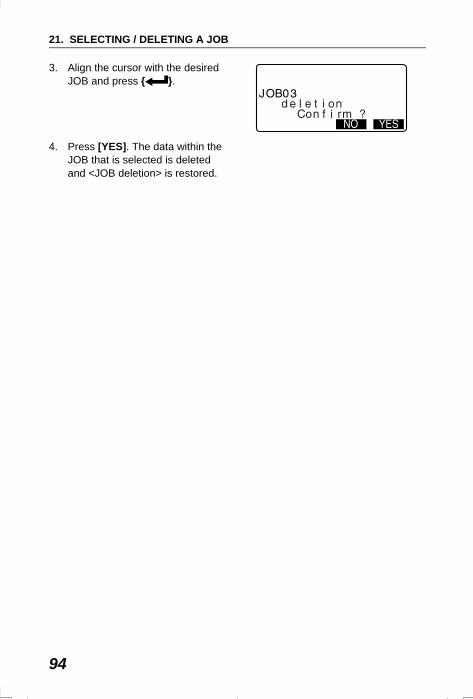
21. SELECTING / DELETING A JOB
94
3. Align the cursor with the desired JOB and press { }.
4. Press [YES]. The data within the JOB that is selected is deleted and <JOB deletion> is restored.
SET2120_21.fm 94 ページ 2001年12月7日 金曜日 午後1時3分
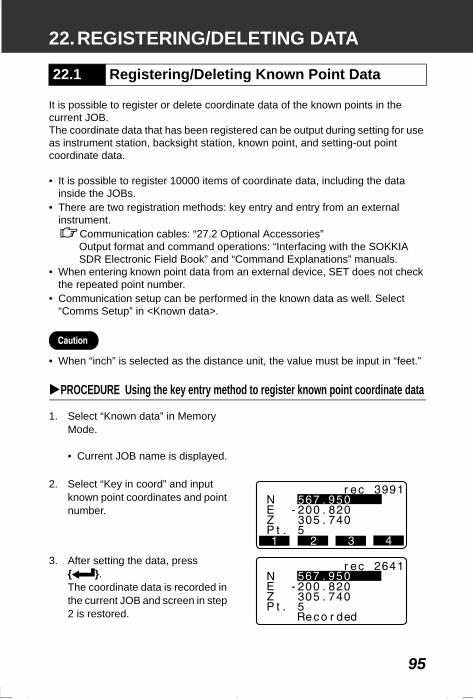
95
22.REGISTERING/DELETING DATA
It is possible to register or delete coordinate data of the known points in the current JOB.The coordinate data that has been registered can be output during setting for use as instrument station, backsight station, known point, and setting-out point coordinate data.
• It is possible to register 10000 items of coordinate data, including the data inside the JOBs.
• There are two registration methods: key entry and entry from an external instrument.
Communication cables: “27.2 Optional Accessories”Output format and command operations: “Interfacing with the SOKKIA SDR Electronic Field Book” and “Command Explanations” manuals.
• When entering known point data from an external device, SET does not check the repeated point number.
• Communication setup can be performed in the known data as well. Select “Comms Setup” in <Known data>.
• When “inch” is selected as the distance unit, the value must be input in “feet.”
PROCEDURE Using the key entry method to register known point coordinate data
1. Select “Known data” in Memory Mode.
• Current JOB name is displayed.
2. Select “Key in coord” and input known point coordinates and point number.
3. After setting the data, press { }. The coordinate data is recorded in the current JOB and screen in step 2 is restored.
22.1 Registering/Deleting Known Point Data
SET2120_22.fm 95 ページ 2001年12月7日 金曜日 午後1時3分
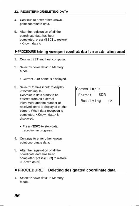
22. REGISTERING/DELETING DATA
96
4. Continue to enter other known point coordinate data.
5. After the registration of all the coordinate data has been completed, press {ESC} to restore <Known data>.
PROCEDURE Entering known point coordinate data from an external instrument
1. Connect SET and host computer.
2. Select “Known data” in Memory Mode.
• Current JOB name is displayed.
3. Select “Comms input” to display <Comms input>.Coordinate data starts to be entered from an external instrument and the number of received items is displayed on the screen. When data reception is completed, <Known data> is displayed.
• Press {ESC} to stop data reception in progress.
4. Continue to enter other known point coordinate data.
5. After the registration of all the coordinate data has been completed, press {ESC} to restore <Known data>.
PROCEDURE Deleting designated coordinate data
1. Select “Known data” in Memory Mode.
SET2120_22.fm 96 ページ 2001年12月7日 金曜日 午後1時3分
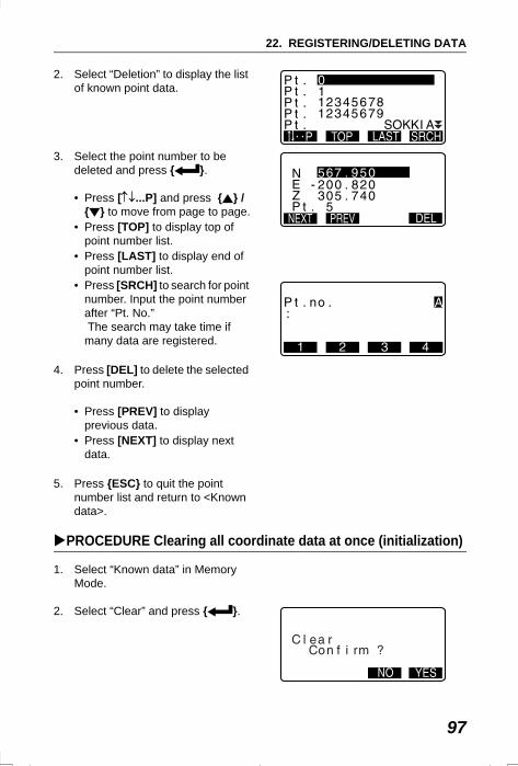
97
22. REGISTERING/DELETING DATA
2. Select “Deletion” to display the list of known point data.
3. Select the point number to be deleted and press { }.
• Press [↑↓...P] and press { } / { } to move from page to page.
• Press [TOP] to display top of point number list.
• Press [LAST] to display end of point number list.
• Press [SRCH] to search for point number. Input the point number after “Pt. No.” The search may take time if many data are registered.
4. Press [DEL] to delete the selected point number.
• Press [PREV] to display previous data.
• Press [NEXT] to display next data.
5. Press {ESC} to quit the point number list and return to <Known data>.
PROCEDURE Clearing all coordinate data at once (initialization)
1. Select “Known data” in Memory Mode.
2. Select “Clear” and press { }.
SET2120_22.fm 97 ページ 2001年12月7日 金曜日 午後1時3分
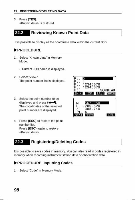
22. REGISTERING/DELETING DATA
98
3. Press [YES]. <Known data> is restored.
It is possible to display all the coordinate data within the current JOB.
PROCEDURE
1. Select “Known data” in Memory Mode.
• Current JOB name is displayed.
2. Select “View.” The point number list is displayed.
3. Select the point number to be displayed and press { }. The coordinates of the selected point number are displayed.
4. Press {ESC} to restore the point number list.Press {ESC} again to restore <Known data>.
It is possible to save codes in memory. You can also read in codes registered in memory when recording instrument station data or observation data.
PROCEDURE Inputting Codes
1. Select “Code” in Memory Mode.
22.2 Reviewing Known Point Data
22.3 Registering/Deleting Codes
SET2120_22.fm 98 ページ 2001年12月7日 金曜日 午後1時3分
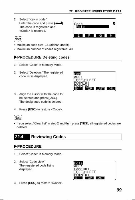
99
22. REGISTERING/DELETING DATA
2. Select “Key in code.”Enter the code and press { }. The code is registered and <Code> is restored.
• Maximum code size: 16 (alphanumeric)• Maximum number of codes registered: 40
PROCEDURE Deleting codes
1. Select “Code” in Memory Mode.
2. Select “Deletion.” The registered code list is displayed.
3. Align the cursor with the code to be deleted and press [DEL].The designated code is deleted.
4. Press {ESC} to restore <Code>.
• If you select “Clear list” in step 2 and then press [YES], all registered codes are deleted.
PROCEDURE
1. Select “Code” in Memory Mode.
2. Select “Code view.” The registered code list is displayed.
3. Press {ESC} to restore <Code>.
22.4 Reviewing Codes
SET2120_22.fm 99 ページ 2001年12月7日 金曜日 午後1時3分
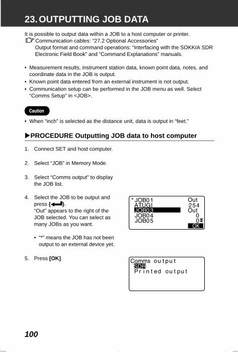
100
23.OUTPUTTING JOB DATAIt is possible to output data within a JOB to a host computer or printer.
Communication cables: “27.2 Optional Accessories”Output format and command operations: “Interfacing with the SOKKIA SDR Electronic Field Book” and “Command Explanations” manuals.
• Measurement results, instrument station data, known point data, notes, and coordinate data in the JOB is output.
• Known point data entered from an external instrument is not output. • Communication setup can be performed in the JOB menu as well. Select
“Comms Setup” in <JOB>.
• When “inch” is selected as the distance unit, data is output in “feet.”
PROCEDURE Outputting JOB data to host computer
1. Connect SET and host computer.
2. Select “JOB” in Memory Mode.
3. Select “Comms output” to display the JOB list.
4. Select the JOB to be output and press { }. “Out” appears to the right of the JOB selected. You can select as many JOBs as you want.
• “*” means the JOB has not been output to an external device yet.
5. Press [OK].
SET310_23.fm 100 ページ 2001年12月11日 火曜日 午前10時8分
101
23. OUTPUTTING JOB DATA
6. Select the output format and press { }. Output starts. When the output is complete, the JOB list is restored. It is possible to continue output of the next JOB.
• To stop output, press {ESC}.
PROCEDURE Outputting JOB data to printer
1. Select “JOB” in Memory Mode.
2. Select “Comms output” to display the JOB list.
3. Select the JOB to be output and press { }. “Out” appears to the right of the JOB selected. You can select as many JOBs as you want.
4. Press [OK].
5. Connect SET and printer.
6. Turn ON the printer.
7. Select "Printed output" and press { }. Output starts. When the output is complete, the JOB list is restored. It is possible to continue output of the next JOB.
SET310_23.fm 101 ページ 2001年12月11日 火曜日 午前10時8分
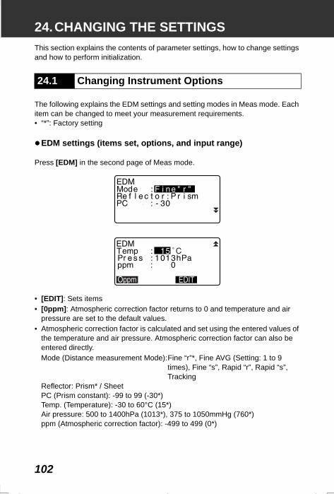
102
24.CHANGING THE SETTINGSThis section explains the contents of parameter settings, how to change settings and how to perform initialization.
The following explains the EDM settings and setting modes in Meas mode. Each item can be changed to meet your measurement requirements. • “*”: Factory setting
EDM settings (items set, options, and input range)
Press [EDM] in the second page of Meas mode.
• [EDIT]: Sets items• [0ppm]: Atmospheric correction factor returns to 0 and temperature and air
pressure are set to the default values.• Atmospheric correction factor is calculated and set using the entered values of
the temperature and air pressure. Atmospheric correction factor can also be entered directly.Mode (Distance measurement Mode):Fine “r”*, Fine AVG (Setting: 1 to 9
times), Fine “s”, Rapid “r”, Rapid “s”, Tracking
Reflector: Prism* / SheetPC (Prism constant): -99 to 99 (-30*)Temp. (Temperature): -30 to 60°C (15*) Air pressure: 500 to 1400hPa (1013*), 375 to 1050mmHg (760*)ppm (Atmospheric correction factor): -499 to 499 (0*)
24.1 Changing Instrument Options
SET310_24.fm 102 ページ 2001年12月11日 火曜日 午前9時30分
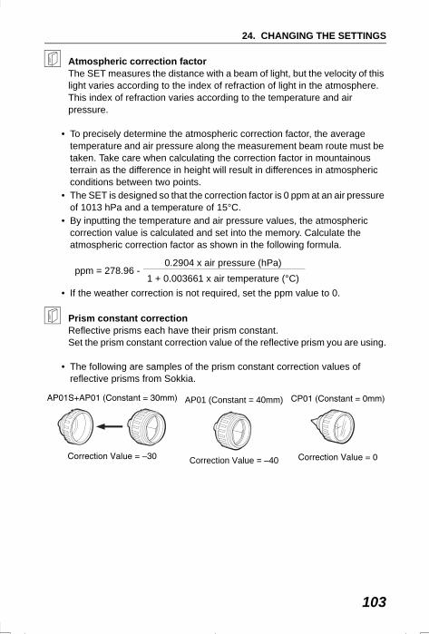
103
24. CHANGING THE SETTINGS
Atmospheric correction factorThe SET measures the distance with a beam of light, but the velocity of this light varies according to the index of refraction of light in the atmosphere. This index of refraction varies according to the temperature and air pressure.
• To precisely determine the atmospheric correction factor, the average temperature and air pressure along the measurement beam route must be taken. Take care when calculating the correction factor in mountainous terrain as the difference in height will result in differences in atmospheric conditions between two points.
• The SET is designed so that the correction factor is 0 ppm at an air pressure of 1013 hPa and a temperature of 15°C.
• By inputting the temperature and air pressure values, the atmospheric correction value is calculated and set into the memory. Calculate the atmospheric correction factor as shown in the following formula.
• If the weather correction is not required, set the ppm value to 0.
Prism constant correctionReflective prisms each have their prism constant.Set the prism constant correction value of the reflective prism you are using.
• The following are samples of the prism constant correction values of reflective prisms from Sokkia.
ppm = 278.96 -0.2904 x air pressure (hPa)
1 + 0.003661 x air temperature (°C)
AP01 (Constant = 40mm)
Correction Value = –40
SET310_24.fm 103 ページ 2001年12月11日 火曜日 午前9時30分
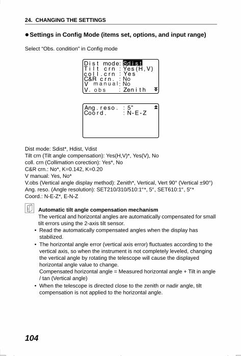
24. CHANGING THE SETTINGS
104
Settings in Config Mode (items set, options, and input range)
Select “Obs. condition” in Config mode
Dist mode: Sdist*, Hdist, VdistTilt crn (Tilt angle compensation): Yes(H,V)*, Yes(V), Nocoll. crn (Collimation corection): Yes*, NoC&R crn.: No*, K=0.142, K=0.20V manual: Yes, No*V.obs (Vertical angle display method): Zenith*, Vertical, Vert 90° (Vertical ±90°)Ang. reso. (Angle resolution): SET210/310/510:1″*, 5″, SET610:1″, 5″*Coord.: N-E-Z*, E-N-Z
Automatic tilt angle compensation mechanismThe vertical and horizontal angles are automatically compensated for small tilt errors using the 2-axis tilt sensor.
• Read the automatically compensated angles when the display has stabilized.
• The horizontal angle error (vertical axis error) fluctuates according to the vertical axis, so when the instrument is not completely leveled, changing the vertical angle by rotating the telescope will cause the displayed horizontal angle value to change. Compensated horizontal angle = Measured horizontal angle + Tilt in angle / tan (Vertical angle)
• When the telescope is directed close to the zenith or nadir angle, tilt compensation is not applied to the horizontal angle.
)
::
::
SET310_24.fm 104 ページ 2002年8月19日 月曜日 午後2時13分
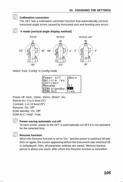
105
24. CHANGING THE SETTINGS
Collimation correction The SET has a collimation correction function that automatically corrects horizontal angle errors caused by horizontal axis and leveling axis errors.
V mode (vertical angle display method)
Select “Instr. Config” in Config mode
Power off: 5min, 10min, 15min, 30min*, NoReticle lev: 0 to 5 level (3*)Contrast: 1 to 10 level (5*)Resume: On, Off*EDM standby: On, Off*EDM ALC: Hold*, Free
Power-saving automatic cut-offTo save power, power to the SET is automatically cut off if it is not operated for the selected time.
Resume functionWhen the Resume function is set to “On,” and the power is switched off and then on again, the screen appearing before the instrument was switched off is redisplayed. Also, all parameter settings are saved. Memory backup period is about one week, after which the Resume function is cancelled.
SET310_24.fm 105 ページ 2001年12月11日 火曜日 午前9時30分
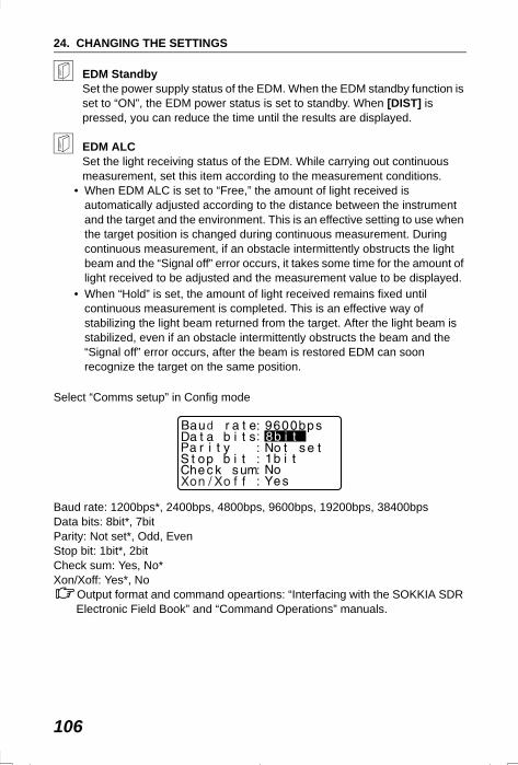
24. CHANGING THE SETTINGS
106
EDM Standby Set the power supply status of the EDM. When the EDM standby function is set to “ON”, the EDM power status is set to standby. When [DIST] is pressed, you can reduce the time until the results are displayed.
EDM ALCSet the light receiving status of the EDM. While carrying out continuous measurement, set this item according to the measurement conditions.
• When EDM ALC is set to “Free,” the amount of light received is automatically adjusted according to the distance between the instrument and the target and the environment. This is an effective setting to use when the target position is changed during continuous measurement. During continuous measurement, if an obstacle intermittently obstructs the light beam and the “Signal off” error occurs, it takes some time for the amount of light received to be adjusted and the measurement value to be displayed.
• When “Hold” is set, the amount of light received remains fixed until continuous measurement is completed. This is an effective way of stabilizing the light beam returned from the target. After the light beam is stabilized, even if an obstacle intermittently obstructs the beam and the “Signal off” error occurs, after the beam is restored EDM can soon recognize the target on the same position.
Select “Comms setup” in Config mode
Baud rate: 1200bps*, 2400bps, 4800bps, 9600bps, 19200bps, 38400bpsData bits: 8bit*, 7bitParity: Not set*, Odd, EvenStop bit: 1bit*, 2bitCheck sum: Yes, No*Xon/Xoff: Yes*, No
Output format and command opeartions: “Interfacing with the SOKKIA SDR Electronic Field Book” and “Command Operations” manuals.
d
SET310_24.fm 106 ページ 2001年12月11日 火曜日 午前9時30分
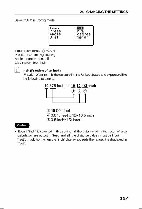
107
24. CHANGING THE SETTINGS
Select “Unit” in Config mode
Temp. (Temperature): °C*, °FPress.: hPa*, mmHg, inchHgAngle: degree*, gon, milDist: meter*, feet, inch
Inch (Fraction of an inch)“Fraction of an inch” is the unit used in the United States and expressed like the following example.
• Even if “inch” is selected in this setting, all the data including the result of area calculation are output in “feet” and all the distance values must be input in “feet”. In addition, when the “inch” display exceeds the range, it is displayed in “feet”.
SET310_24.fm 107 ページ 2002年8月19日 月曜日 午後2時16分
24. CHANGING THE SETTINGS
108
It is possible to allocate the softkeys in Meas mode to suit the measurement conditions. It is possible to operate the SET efficiently because unique softkey allocations can be preset to suit various applications and the ways that different operators handle the instrument.
• The current softkey allocations are retained until they are revised again, even when the power is cut off.
• It is possible to register two sets of key function allocations: user setting 1 and user setting 2.
• It is possible to recall the softkey arrays registered for User 1 and User 2 as necessary.
• When softkey allocations are recorded and registered, the previously recorded key settings are cleared. When a softkey array is recalled, the key array is changed to the key array that has been recalled, clearing the previous key array. Be sure to remember this.
The following are the softkey allocations when the SET was shipped.
Page 1 [DIST] [ SHV] [0SET] [COORD]Page 2 [MENU] [TILT] [H.ANG] [EDM]Page 3 [MLM] [OFFSET] [REC] [S-O]
The following functions can be allocated to the softkeys.[DIST] : Distance measurement[ SHV] : Switch between angle display and distance display[0SET] : Set horizontal angle to 0[COORD] : Coordinates measurement[REP] : Repetition measurement[MLM] : Missing line measurement[S-O] : Setting-out measurement
[OFFSET] : Offset measurement[REC] : To Record menu[EDM] : Setting EDM[H.ANG] : Set required horizontal angle[TILT] : Display tilt angle
24.2 Allocating Key Functions
SET310_24.fm 108 ページ 2001年12月11日 火曜日 午前9時30分
109
24. CHANGING THE SETTINGS
[MENU] : To Menu mode (Coordinates measurement, setting-out measurement, offset measurement, repetition measurement, missing line measurement, REM measurement, resection measurement, surface area measurement, set-out line, point projection)
[REM] : REM measurement[RESEC] : Resection measurement[R/L] : Select horizontal angle right/left[ZA / %] : Switch between zenith angle/slope in %[HOLD] : Hold horizontal angle/release horizontal angle[RCL] : Display final measurement data[D_OUT] : Output measurement results to an external instrument[AIM] : Return signal[AREA] : Surface area measurement[F/M] : Switch between meters/feet[HT] : Set the instrument station height and target height[S-O LINE] : Setting-out line measurement[P-PROJ] : Point projection measurement[---] : No functions set
Softkey Allocation ExamplesIt is possible to allocate the same key to each page (example 1). The same function can be allocated to more than one key on the same page (example 2). And it is also possible to allocate a function to only one key (example 3).
Allocation example 1:P1 [DIST] [ SHV] [H.ANG] [EDM]P2 [DIST] [ SHV] [H.ANG] [EDM]
Allocation example 2:P1 [DIST] [DIST] [ SHV] [ SHV]
Allocation example 3:P1 [DIST] [ SHV] [– – –] [– – –]
SET310_24.fm 109 ページ 2001年12月11日 火曜日 午前9時30分
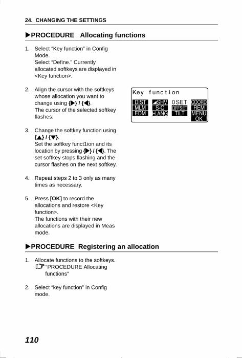
24. CHANGING THE SETTINGS
110
PROCEDURE Allocating functions
1. Select “Key function” in Config Mode. Select “Define.” Currently allocated softkeys are displayed in <Key function>.
2. Align the cursor with the softkeys whose allocation you want to change using { } / { }. The cursor of the selected softkey flashes.
3. Change the softkey function using { } / { }.Set the softkey funct1ion and its location by pressing { } / { }. The set softkey stops flashing and the cursor flashes on the next softkey.
4. Repeat steps 2 to 3 only as many times as necessary.
5. Press [OK] to record the
allocations and restore <Key function>.The functions with their new allocations are displayed in Meas mode.
PROCEDURE Registering an allocation
1. Allocate functions to the softkeys.“PROCEDURE Allocating functions”
2. Select “key function” in Config mode.
SET310_24.fm 110 ページ 2001年12月11日 火曜日 午前9時30分
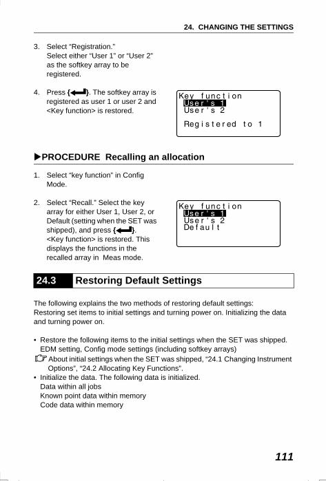
111
24. CHANGING THE SETTINGS
3. Select “Registration.”Select either “User 1” or “User 2” as the softkey array to be registered.
4. Press { }. The softkey array is registered as user 1 or user 2 and <Key function> is restored.
PROCEDURE Recalling an allocation
1. Select “key function” in Config Mode.
2. Select “Recall.” Select the key array for either User 1, User 2, or Default (setting when the SET was shipped), and press { }.<Key function> is restored. This displays the functions in the recalled array in Meas mode.
The following explains the two methods of restoring default settings: Restoring set items to initial settings and turning power on. Initializing the data and turning power on.
• Restore the following items to the initial settings when the SET was shipped.EDM setting, Config mode settings (including softkey arrays)
About initial settings when the SET was shipped, “24.1 Changing Instrument Options”, “24.2 Allocating Key Functions”.
• Initialize the data. The following data is initialized.Data within all jobsKnown point data within memoryCode data within memory
24.3 Restoring Default Settings
SET310_24.fm 111 ページ 2001年12月11日 火曜日 午前9時30分
24. CHANGING THE SETTINGS
112
PROCEDURE Restoring set items to initial settings and turning power on
1. Turn the power off.
2. While pressing {F4} and {BS}, press {ON}.
3. The SET is turned on, “Default set” appears on the screen and all items are restored to their initial settings.
PROCEDURE Initializing the data and turning the power on
1. Turn the power off.
2. While pressing {F1}, {F3} and {BS}, press {ON}.
3. The SET is turned on, “Clearing memory...” appears on the screen and all items are restored to their initial settings.
SET310_24.fm 112 ページ 2001年12月11日 火曜日 午前9時30分
113
25.WARNING AND ERROR MESSAGESThe following is a list of the error messages displayed by the SET and the meaning of each message. If the same error message is repeated or if any message not shown below appears, the instrument has malfunctioned. Contact your Sokkia agent.
Bad conditionDistance measurement conditions are poor.Either sight the target again, or when using a reflective prism, increase the number of reflective prisms.
Calculation errorCoordinates identical to the known point coordinates observed during resection exist. Set another known point so that the known point coordinates do not coincide.
Checksum errorA sending / repetition error has occured between the SET and external equipment.Send / receive the data again.
Communication errorA reception error has occurred in coordinate data from an external instrument.Check the settings of parameters concerning communication conditions.
“24.1 Changing Instrument Options Settings in Config Mode ”
Flash write error!Flash mount error!
It is impossible to read in data.Contact your Sokkia agent.
Invalid baselineDuring setting-out line measurement or point projection measurment, baseline has not been defined correctly.
Memory is fullThere is no more room to enter data.Record the data again after deleting unnecessary data from the JOB or coordinate data from the memory.
SET2120_25.fm 113 ページ 2001年12月7日 金曜日 午後1時5分
25. WARNING AND ERROR MESSAGES
114
Need 1st obsDuring missing line measurement, the observation of the starting position was not completed normally.Sight the starting position accurately and press [OBS] to perform the measurement again.
Need 2nd obsDuring missing line measurement, the observation of the target was not completed normally.Sight the target accurately and press [MLM] to perform the measurement again.
Need offset pt. Observation of the offset point during offset measurement was not completed normally.Sight the offset point accurately and press [OBS] to perform the measurement again.
Need prism obsDuring REM measurement, the observation of the target was not completed normally.Sight the target accurately and press [OBS] to perform measurement again.
No dataWhen searching for or reading in coordinate data or searching for code data, the search stopped either because the item in question does not exist or the data volume is large.
No solutionThe calculation of the instrument station coordinates during resection does not converge. Assess the results and if necessary, perform the observation again.
Out of range The tilt of the instrument exceeds the tilt angle compensation range during measurement.Sight again within ±3′.
SET2120_25.fm 114 ページ 2001年12月7日 金曜日 午後1時5分
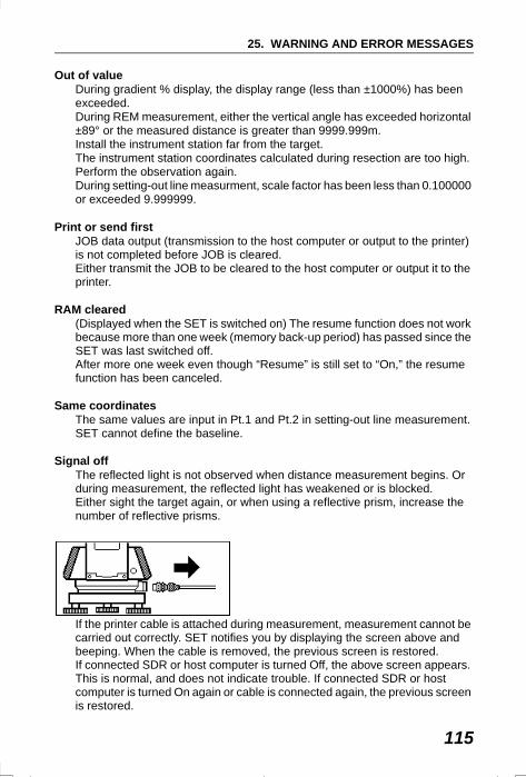
115
25. WARNING AND ERROR MESSAGES
Out of valueDuring gradient % display, the display range (less than ±1000%) has been exceeded.During REM measurement, either the vertical angle has exceeded horizontal ±89° or the measured distance is greater than 9999.999m.Install the instrument station far from the target.The instrument station coordinates calculated during resection are too high.Perform the observation again.During setting-out line measurment, scale factor has been less than 0.100000 or exceeded 9.999999.
Print or send firstJOB data output (transmission to the host computer or output to the printer) is not completed before JOB is cleared.Either transmit the JOB to be cleared to the host computer or output it to the printer.
RAM cleared(Displayed when the SET is switched on) The resume function does not work because more than one week (memory back-up period) has passed since the SET was last switched off. After more one week even though “Resume” is still set to “On,” the resume function has been canceled.
Same coordinatesThe same values are input in Pt.1 and Pt.2 in setting-out line measurement. SET cannot define the baseline.
Signal offThe reflected light is not observed when distance measurement begins. Or during measurement, the reflected light has weakened or is blocked.Either sight the target again, or when using a reflective prism, increase the number of reflective prisms.
If the printer cable is attached during measurement, measurement cannot be carried out correctly. SET notifies you by displaying the screen above and beeping. When the cable is removed, the previous screen is restored.If connected SDR or host computer is turned Off, the above screen appears. This is normal, and does not indicate trouble. If connected SDR or host computer is turned On again or cable is connected again, the previous screen is restored.
SET2120_25.fm 115 ページ 2001年12月7日 金曜日 午後1時5分
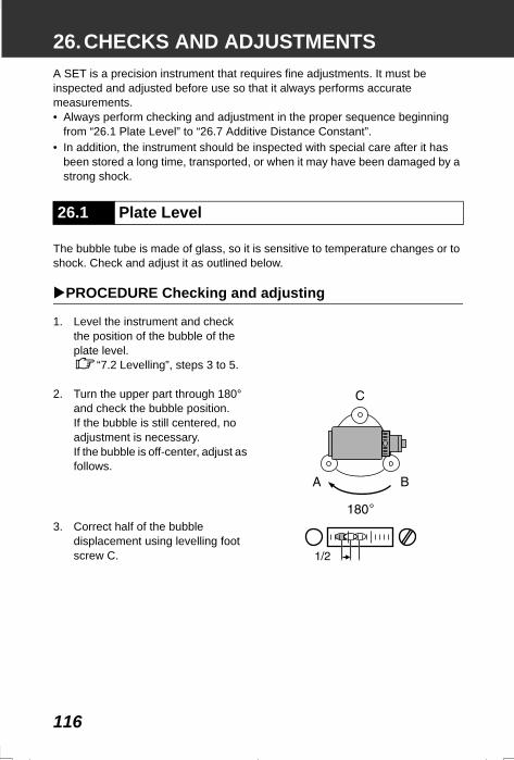
116
26.CHECKS AND ADJUSTMENTSA SET is a precision instrument that requires fine adjustments. It must be inspected and adjusted before use so that it always performs accurate measurements.• Always perform checking and adjustment in the proper sequence beginning
from “26.1 Plate Level” to “26.7 Additive Distance Constant”.• In addition, the instrument should be inspected with special care after it has
been stored a long time, transported, or when it may have been damaged by a strong shock.
The bubble tube is made of glass, so it is sensitive to temperature changes or to shock. Check and adjust it as outlined below.
PROCEDURE Checking and adjusting
1. Level the instrument and check the position of the bubble of the plate level.
“7.2 Levelling”, steps 3 to 5.
2. Turn the upper part through 180° and check the bubble position.If the bubble is still centered, no adjustment is necessary.If the bubble is off-center, adjust as follows.
3. Correct half of the bubble displacement using levelling foot screw C.
26.1 Plate Level
SET2120_26.fm 116 ページ 2001年12月7日 金曜日 午後1時5分
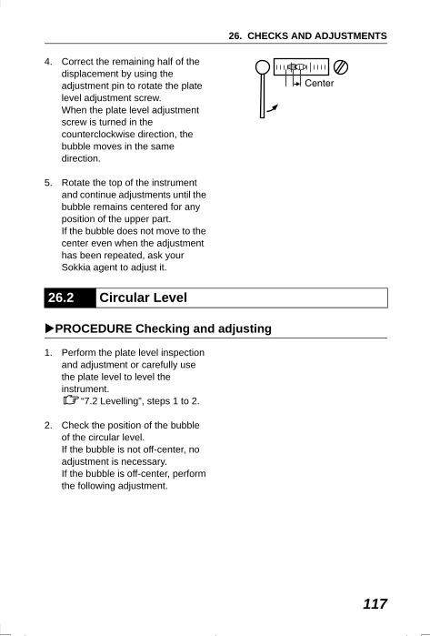
117
26. CHECKS AND ADJUSTMENTS
4. Correct the remaining half of the displacement by using the adjustment pin to rotate the plate level adjustment screw. When the plate level adjustment screw is turned in the counterclockwise direction, the bubble moves in the same direction.
5. Rotate the top of the instrument and continue adjustments until the bubble remains centered for any position of the upper part.If the bubble does not move to the center even when the adjustment has been repeated, ask your Sokkia agent to adjust it.
PROCEDURE Checking and adjusting
1. Perform the plate level inspection and adjustment or carefully use the plate level to level the instrument.
“7.2 Levelling”, steps 1 to 2.
2. Check the position of the bubble of the circular level.If the bubble is not off-center, no adjustment is necessary.If the bubble is off-center, perform the following adjustment.
26.2 Circular Level
SET2120_26.fm 117 ページ 2001年12月7日 金曜日 午後1時5分
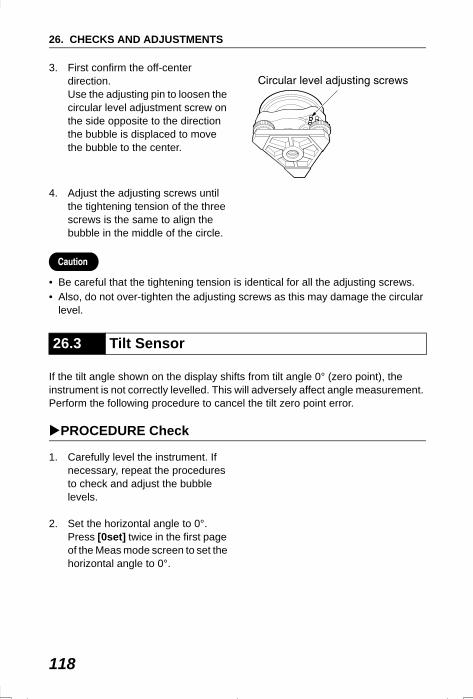
26. CHECKS AND ADJUSTMENTS
118
3. First confirm the off-center direction.Use the adjusting pin to loosen the circular level adjustment screw on the side opposite to the direction the bubble is displaced to move the bubble to the center.
4. Adjust the adjusting screws until the tightening tension of the three screws is the same to align the bubble in the middle of the circle.
• Be careful that the tightening tension is identical for all the adjusting screws.• Also, do not over-tighten the adjusting screws as this may damage the circular
level.
If the tilt angle shown on the display shifts from tilt angle 0° (zero point), the instrument is not correctly levelled. This will adversely affect angle measurement. Perform the following procedure to cancel the tilt zero point error.
PROCEDURE Check
1. Carefully level the instrument. If necessary, repeat the procedures to check and adjust the bubble levels.
2. Set the horizontal angle to 0°. Press [0set] twice in the first page of the Meas mode screen to set the horizontal angle to 0°.
26.3 Tilt Sensor
SET2120_26.fm 118 ページ 2001年12月7日 金曜日 午後1時5分
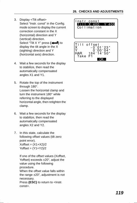
119
26. CHECKS AND ADJUSTMENTS
3. Display <Tilt offset>Select “Instr. const” in the Config. mode screen to display the current correction constant in the X (horizontal) direction and Y (vertical) direction.Select “Tilt X Y” press { } to display the tilt angle in the X (sighting) direction and Y (horizontal axis) direction.
4. Wait a few seconds for the display to stabilize, then read the automatically compensated angles X1 and Y1.
5. Rotate the top of the instrument through 180°.Loosen the horizontal clamp and turn the instrument 180° while referring to the displayed horizontal angle, then retighten the clamp.
6. Wait a few seconds for the display
to stabilize, then read the automatically compensated angles X2 and Y2.
7. In this state, calculate the following offset values (tilt zero point error).Xoffset = (X1+X2)/2Yoffset = (Y1+Y2)/2
If one of the offset values (Xoffset, Yoffset) exceeds ±20", adjust the value using the following procedure.When the offset value falls within the range ±20", adjustment is not necessary. Press {ESC} to return to <Instr. const>.
SET2120_26.fm 119 ページ 2001年12月7日 金曜日 午後1時5分
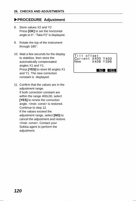
26. CHECKS AND ADJUSTMENTS
120
PROCEDURE Adjustment
8. Store values X2 and Y2Press [OK] to set the horizontal angle to 0°. “Take F2” is displayed.
9. Rotate the top of the instrument through 180°.
10. Wait a few seconds for the display to stabilize, then store the automatically compensated angles X1 and Y1.Press [YES] to store tilt angles X1 and Y1. The new correction constant is displayed.
11. Confirm that the values are in the adjustment range.If both correction constant are within the range 400±30, select [YES] to renew the correction angle. <Instr. const> is restored. Continue to step 12.If the values exceed the adjustment range, select [NO] to cancel the adjustment and restore <Instr. const>. Contact your Sokkia agent to perform the adjustment.
SET2120_26.fm 120 ページ 2001年12月7日 金曜日 午後1時5分
121
26. CHECKS AND ADJUSTMENTS
PROCEDURE Recheck
12. Press { } at <Instr. const>.
13. Wait a few seconds for the display to stabilize, then read the automatically compensated angles X3 and Y3.
14. Rotate the top of the instrument through 180°.
15. Wait a few seconds for the display to stabilize, then read the automatically compensated angles X4 and Y4.
16. In this state, the following offset values (tilt zero point error) are calculated.Xoffset = (X3+X4)/2Yoffset = (Y3+Y4)/2When both offset values fall within the range ±20", adjustment is completed. Press {ESC} to return to <Instr. const>.
If one of the offset values (Xoffset, Yoffset) exceeds ±20", repeat the check and adjustment procedures from the beginning. If the difference continues to exceed ±20" after repeating the check 2 or 3 times, have your Sokkia agent perform the adjustment.
SET2120_26.fm 121 ページ 2001年12月7日 金曜日 午後1時5分
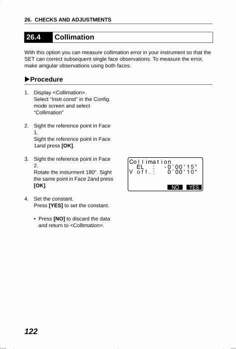
26. CHECKS AND ADJUSTMENTS
122
With this option you can measure collimation error in your instrument so that the SET can correct subsequent single face observations. To measure the error, make amgular observations using both faces.
Procedure
1. Display <Collimation>.Select “Instr.const” in the Config. mode screen and select “Collimation”
2. Sight the reference point in Face 1. Sight the reference point in Face 1and press [OK].
3. Sight the reference point in Face 2.Rotate the insturment 180°. Sight the same point in Face 2and press [OK].
4. Set the constant.Press [YES] to set the constant.
• Press [NO] to discard the data and return to <Colltmation>.
26.4 Collimation
SET2120_26.fm 122 ページ 2001年12月7日 金曜日 午後1時5分
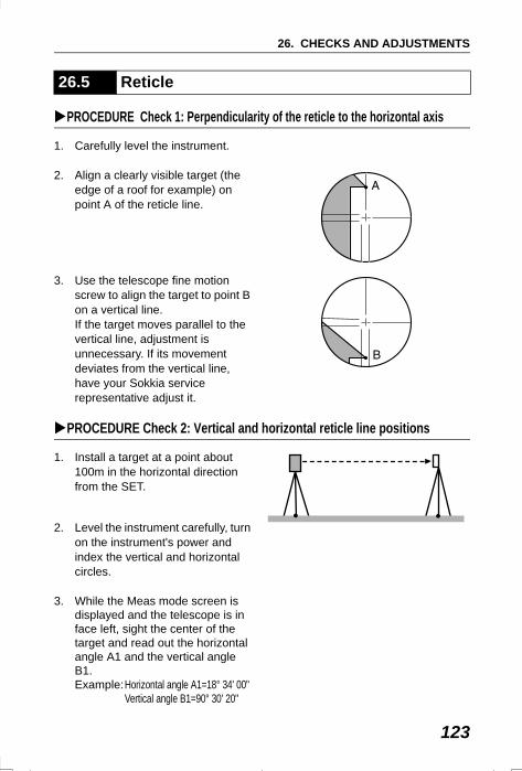
123
26. CHECKS AND ADJUSTMENTS
PROCEDURE Check 1: Perpendicularity of the reticle to the horizontal axis
1. Carefully level the instrument.
2. Align a clearly visible target (the edge of a roof for example) on point A of the reticle line.
3. Use the telescope fine motion screw to align the target to point B on a vertical line.If the target moves parallel to the vertical line, adjustment is unnecessary. If its movement deviates from the vertical line, have your Sokkia service representative adjust it.
PROCEDURE Check 2: Vertical and horizontal reticle line positions
1. Install a target at a point about 100m in the horizontal direction from the SET.
2. Level the instrument carefully, turn on the instrument's power and index the vertical and horizontal circles.
3. While the Meas mode screen is displayed and the telescope is in face left, sight the center of the target and read out the horizontal angle A1 and the vertical angle B1.Example:Horizontal angle A1=18° 34' 00"
Vertical angle B1=90° 30' 20"
26.5 Reticle
SET310_26.fm 123 ページ 2002年6月25日 火曜日 午前10時45分
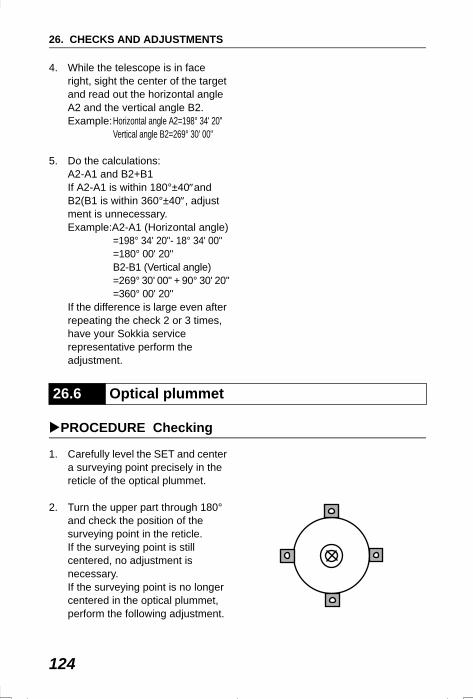
26. CHECKS AND ADJUSTMENTS
124
4. While the telescope is in face right, sight the center of the target and read out the horizontal angle A2 and the vertical angle B2.Example:Horizontal angle A2=198° 34' 20" Vertical angle B2=269° 30' 00"
5. Do the calculations: A2-A1 and B2+B1If A2-A1 is within 180°±40″and B2(B1 is within 360°±40″, adjustment is unnecessary.Example:A2-A1 (Horizontal angle)
=198° 34' 20"- 18° 34' 00"=180° 00' 20"B2-B1 (Vertical angle)=269° 30' 00" + 90° 30' 20"=360° 00' 20"
If the difference is large even after repeating the check 2 or 3 times, have your Sokkia service representative perform the adjustment.
PROCEDURE Checking
1. Carefully level the SET and center a surveying point precisely in the reticle of the optical plummet.
2. Turn the upper part through 180° and check the position of the surveying point in the reticle.If the surveying point is still centered, no adjustment is necessary.If the surveying point is no longer centered in the optical plummet, perform the following adjustment.
26.6 Optical plummet
SET2120_26.fm 124 ページ 2001年12月7日 金曜日 午後1時5分
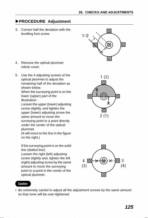
125
26. CHECKS AND ADJUSTMENTS
PROCEDURE Adjustment
3. Correct half the deviation with the levelling foot screw.
4. Remove the optical plummet reticle cover.
5. Use the 4 adjusting screws of the optical plummet to adjust the remaining half of the deviation as shown below. When the surveying point is on the lower (upper) part of the illustration:Loosen the upper (lower) adjusting screw slightly, and tighten the upper (lower) adjusting screw the same amount to move the surveying point to a point directly under the center of the optical plummet.(It will move to the line in the figure on the right.)
If the surveying point is on the solid line (dotted line):Loosen the right (left) adjusting screw slightly and, tighten the left (right) adjusting screw by the same amount to move the surveying point to a point in the center of the optical plummet.
• Be extremely careful to adjust all the adjustment screws by the same amount so that none will be over-tightened.
1 (2)
2 (1)
4 (3)
3 (4)
SET2120_26.fm 125 ページ 2001年12月7日 金曜日 午後1時5分
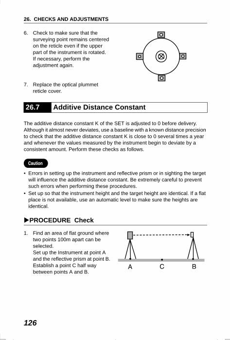
26. CHECKS AND ADJUSTMENTS
126
6. Check to make sure that the surveying point remains centered on the reticle even if the upper part of the instrument is rotated. If necessary, perform the adjustment again.
7. Replace the optical plummet reticle cover.
The additive distance constant K of the SET is adjusted to 0 before delivery. Although it almost never deviates, use a baseline with a known distance precision to check that the additive distance constant K is close to 0 several times a year and whenever the values measured by the instrument begin to deviate by a consistent amount. Perform these checks as follows.
• Errors in setting up the instrument and reflective prism or in sighting the target will influence the additive distance constant. Be extremely careful to prevent such errors when performing these procedures.
• Set up so that the instrument height and the target height are identical. If a flat place is not available, use an automatic level to make sure the heights are identical.
PROCEDURE Check
1. Find an area of flat ground where two points 100m apart can be selected. Set up the Instrument at point A and the reflective prism at point B. Establish a point C half way between points A and B.
26.7 Additive Distance Constant
SET2120_26.fm 126 ページ 2001年12月7日 金曜日 午後1時5分
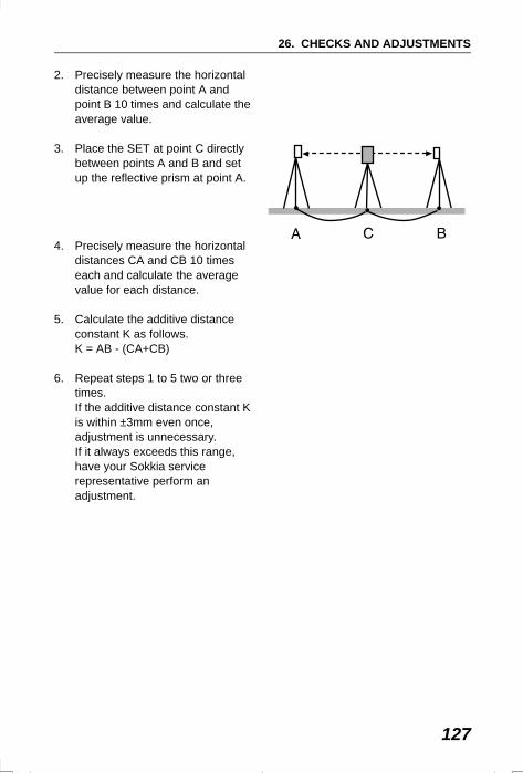
127
26. CHECKS AND ADJUSTMENTS
2. Precisely measure the horizontal distance between point A and point B 10 times and calculate the average value.
3. Place the SET at point C directly between points A and B and set up the reflective prism at point A.
4. Precisely measure the horizontal distances CA and CB 10 times each and calculate the average value for each distance.
5. Calculate the additive distance constant K as follows.K = AB - (CA+CB)
6. Repeat steps 1 to 5 two or three times. If the additive distance constant K is within ±3mm even once, adjustment is unnecessary. If it always exceeds this range, have your Sokkia service representative perform an adjustment.
SET2120_26.fm 127 ページ 2001年12月7日 金曜日 午後1時5分
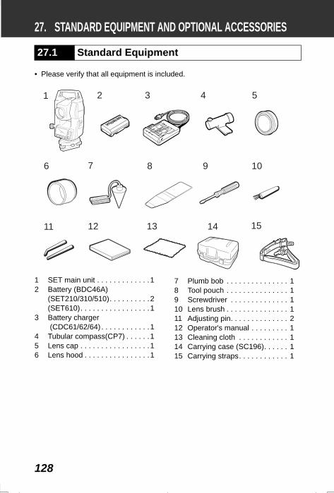
128
27. STANDARD EQUIPMENT AND OPTIONAL ACCESSORIES
• Please verify that all equipment is included.
27.1 Standard Equipment
1 2 3 4 5
6 7 8 9 10
11 12 13 14 15
1 SET main unit . . . . . . . . . . . . .12 Battery (BDC46A)
(SET210/310/510). . . . . . . . . .2 (SET610). . . . . . . . . . . . . . . . .1
3 Battery charger (CDC61/62/64) . . . . . . . . . . . .1
4 Tubular compass(CP7) . . . . . .15 Lens cap . . . . . . . . . . . . . . . . .16 Lens hood . . . . . . . . . . . . . . . .1
7 Plumb bob . . . . . . . . . . . . . . . 18 Tool pouch . . . . . . . . . . . . . . . 19 Screwdriver . . . . . . . . . . . . . . 110 Lens brush . . . . . . . . . . . . . . . 111 Adjusting pin. . . . . . . . . . . . . . 212 Operator's manual . . . . . . . . . 113 Cleaning cloth . . . . . . . . . . . . 114 Carrying case (SC196). . . . . . 115 Carrying straps. . . . . . . . . . . . 1
SET310_27.fm 128 ページ 2002年8月19日 月曜日 午後2時19分
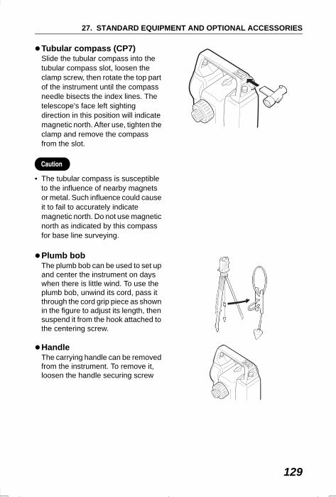
129
27. STANDARD EQUIPMENT AND OPTIONAL ACCESSORIES
Tubular compass (CP7)Slide the tubular compass into the tubular compass slot, loosen the clamp screw, then rotate the top part of the instrument until the compass needle bisects the index lines. The telescope's face left sighting direction in this position will indicate magnetic north. After use, tighten the clamp and remove the compass from the slot.
• The tubular compass is susceptible to the influence of nearby magnets or metal. Such influence could cause it to fail to accurately indicate magnetic north. Do not use magnetic north as indicated by this compass for base line surveying.
Plumb bobThe plumb bob can be used to set up and center the instrument on days when there is little wind. To use the plumb bob, unwind its cord, pass it through the cord grip piece as shown in the figure to adjust its length, then suspend it from the hook attached to the centering screw.
Handle The carrying handle can be removed from the instrument. To remove it, loosen the handle securing screw
SET310_27.fm 129 ページ 2002年2月14日 木曜日 午後6時51分
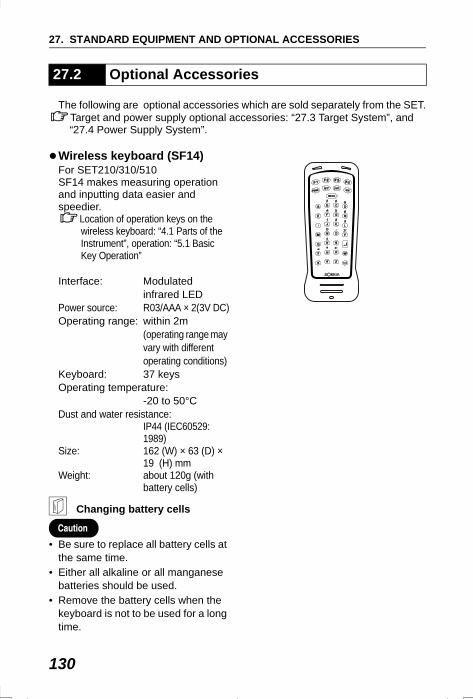
27. STANDARD EQUIPMENT AND OPTIONAL ACCESSORIES
130
The following are optional accessories which are sold separately from the SET.Target and power supply optional accessories: “27.3 Target System”, and “27.4 Power Supply System”.
Wireless keyboard (SF14)For SET210/310/510SF14 makes measuring operation and inputting data easier and speedier.
Location of operation keys on the wireless keyboard: “4.1 Parts of the Instrument”, operation: “5.1 Basic Key Operation”
Interface: Modulated infrared LED
Power source: R03/AAA × 2(3V DC)Operating range: within 2m
(operating range may vary with different operating conditions)
Keyboard: 37 keysOperating temperature:
-20 to 50°CDust and water resistance:
IP44 (IEC60529: 1989)
Size: 162 (W) × 63 (D) × 19 (H) mm
Weight: about 120g (with battery cells)
Changing battery cells
• Be sure to replace all battery cells at the same time.
• Either all alkaline or all manganese batteries should be used.
• Remove the battery cells when the keyboard is not to be used for a long time.
27.2 Optional Accessories
SET310_27.fm 130 ページ 2002年5月17日 金曜日 午後6時24分
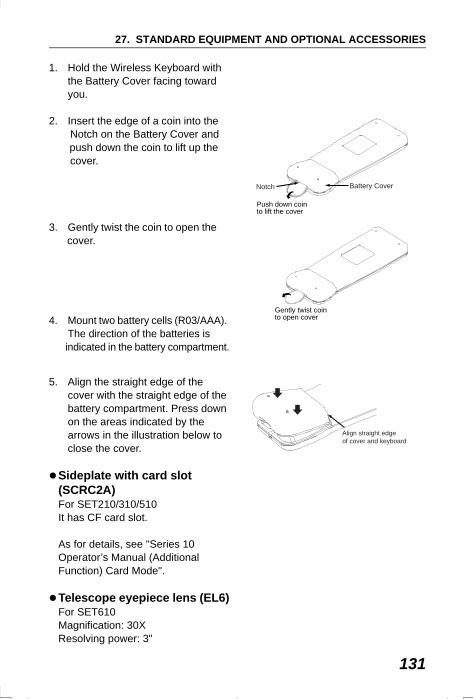
131
27. STANDARD EQUIPMENT AND OPTIONAL ACCESSORIES
1. Hold the Wireless Keyboard with the Battery Cover facing toward you.
2. Insert the edge of a coin into the Notch on the Battery Cover and push down the coin to lift up the cover.
3. Gently twist the coin to open the cover.
4. Mount two battery cells (R03/AAA). The direction of the batteries is
indicated in the battery compartment.
5. Align the straight edge of the cover with the straight edge of the battery compartment. Press down on the areas indicated by the arrows in the illustration below to close the cover.
Sideplate with card slot (SCRC2A)For SET210/310/510It has CF card slot.
As for details, see "Series 10 Operator’s Manual (Additional Function) Card Mode".
Telescope eyepiece lens (EL6)For SET610Magnification: 30XResolving power: 3"
Battery Cover
Push down coin to lift the cover
Notch
Gently twist coin to open cover
Align straight edge of cover and keyboard
SET310_27.fm 131 ページ 2002年8月19日 月曜日 午後5時14分
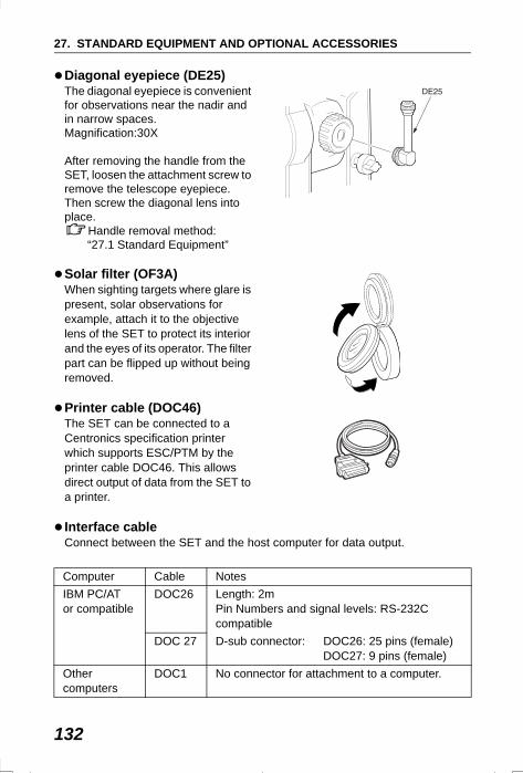
27. STANDARD EQUIPMENT AND OPTIONAL ACCESSORIES
132
Diagonal eyepiece (DE25) The diagonal eyepiece is convenient for observations near the nadir and in narrow spaces. Magnification:30X
After removing the handle from the SET, loosen the attachment screw to remove the telescope eyepiece. Then screw the diagonal lens into place.
Handle removal method: “27.1 Standard Equipment”
Solar filter (OF3A)When sighting targets where glare is present, solar observations for example, attach it to the objective lens of the SET to protect its interior and the eyes of its operator. The filter part can be flipped up without being removed.
Printer cable (DOC46)The SET can be connected to a Centronics specification printer which supports ESC/PTM by the printer cable DOC46. This allows direct output of data from the SET to a printer.
Interface cableConnect between the SET and the host computer for data output.
Computer Cable NotesIBM PC/AT or compatible
DOC26 Length: 2mPin Numbers and signal levels: RS-232C compatible
DOC 27 D-sub connector: DOC26: 25 pins (female)DOC27: 9 pins (female)
Other computers
DOC1 No connector for attachment to a computer.
SET310_27.fm 132 ページ 2002年2月15日 金曜日 午前10時29分
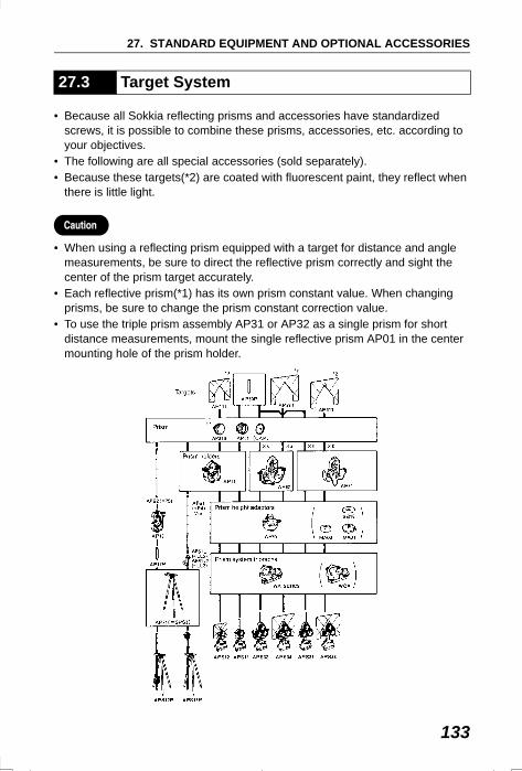
133
27. STANDARD EQUIPMENT AND OPTIONAL ACCESSORIES
• Because all Sokkia reflecting prisms and accessories have standardized screws, it is possible to combine these prisms, accessories, etc. according to your objectives.
• The following are all special accessories (sold separately).• Because these targets(*2) are coated with fluorescent paint, they reflect when
there is little light.
• When using a reflecting prism equipped with a target for distance and angle measurements, be sure to direct the reflective prism correctly and sight the center of the prism target accurately.
• Each reflective prism(*1) has its own prism constant value. When changing prisms, be sure to change the prism constant correction value.
• To use the triple prism assembly AP31 or AP32 as a single prism for short distance measurements, mount the single reflective prism AP01 in the center mounting hole of the prism holder.
27.3 Target System
SET310_27.fm 133 ページ 2002年2月14日 木曜日 午後6時51分
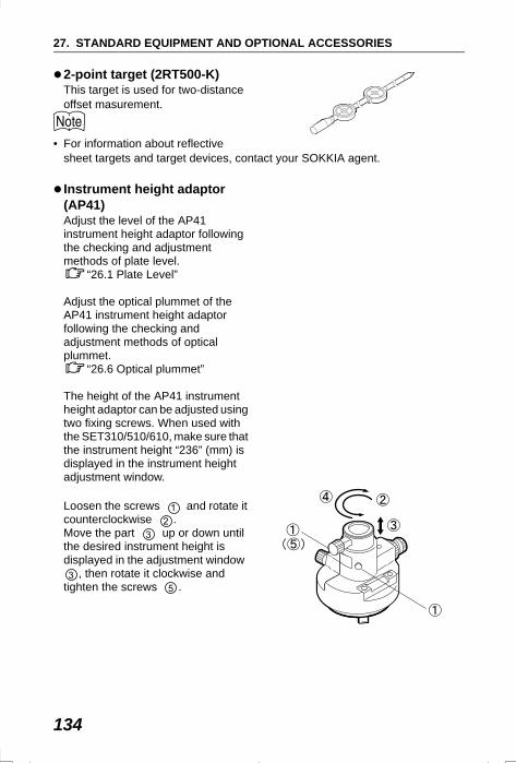
27. STANDARD EQUIPMENT AND OPTIONAL ACCESSORIES
134
2-point target (2RT500-K)This target is used for two-distance offset masurement.
• For information about reflective sheet targets and target devices, contact your SOKKIA agent.
Instrument height adaptor (AP41)Adjust the level of the AP41 instrument height adaptor following the checking and adjustment methods of plate level.
“26.1 Plate Level”
Adjust the optical plummet of the AP41 instrument height adaptor following the checking and adjustment methods of optical plummet.
“26.6 Optical plummet”
The height of the AP41 instrument height adaptor can be adjusted using two fixing screws. When used with the SET310/510/610, make sure that the instrument height “236” (mm) is displayed in the instrument height adjustment window.
Loosen the screws and rotate it counterclockwise .Move the part up or down until the desired instrument height is displayed in the adjustment window
, then rotate it clockwise and tighten the screws .
SET310_27.fm 134 ページ 2002年8月19日 月曜日 午後2時23分
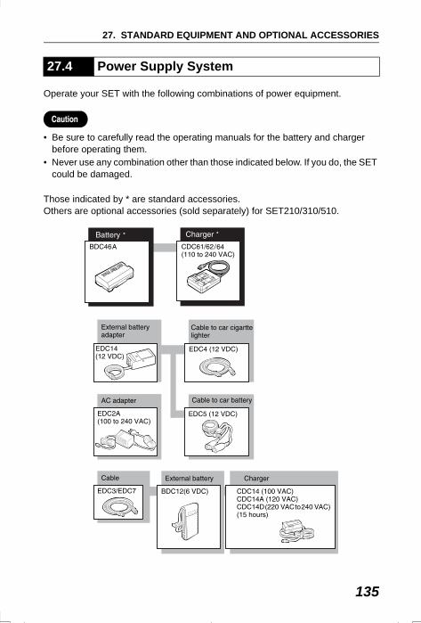
135
27. STANDARD EQUIPMENT AND OPTIONAL ACCESSORIES
Operate your SET with the following combinations of power equipment.
• Be sure to carefully read the operating manuals for the battery and charger before operating them.
• Never use any combination other than those indicated below. If you do, the SET could be damaged.
Those indicated by * are standard accessories. Others are optional accessories (sold separately) for SET210/310/510.
27.4 Power Supply System
SET310_27.fm 135 ページ 2002年5月17日 金曜日 午後7時0分

27. STANDARD EQUIPMENT AND OPTIONAL ACCESSORIES
136
External power supply equipment• When using EDC14, EDC2A, or BDC12, mount the BDC46 in place to maintain
the balance of the instrument.• Make sure that the car cigarette lighter is 12V DC and that its negative terminal
is grounded. Use it with the car engine running. • The EDC14 has a breaker switch. Normally the red mark appears on the
breaker. If it cannot be seen, set the breaker so it is visible.When using the car battery, the breaker will cut off if the poles are not correctly connected.
SET310_27.fm 136 ページ 2002年2月14日 木曜日 午後6時51分
137
28.SPECIFICATIONSExcept where stated, the following specifications apply to all SETs. “SET310” means SET310/SET310S, “SET510” means SET510/SET510S and “SET610” means SET610/610S.
TelescopeLength: 170 mmAperture: 45 mm (EDM: 48 mm)Magnification:
SET210/310/510: 30XSET610: 26X
Image: ErectResolving power:
SET210/310/510: 3"SET610: 3.5"
Field of view: 1° 30'Minimum focus: 1.0 mFocussing screw: 1 speedReticle illumination: 5 brightness levels
Angle measurementHorizontal and Vertical circles type: Rotary absolute encoderAngle units: Degree/Gon/Mil (selectable)Minimum display: 1" (0.2mgon/0.005mil)/5" (1mgon/0.02mil)
(selectable)Accuracy:
SET210: 2" (0.6mgon/0.01mil)SET310: 3" (1mgon/0.015mil) (When “Minimum display” is
set to 1")SET510: 5" (1.5mgon/0.02mil) SET610: 6" (1.9mgon) (0.025mil) (ISO 12857-2 :1997)
Measuring time: Less than 0.5 secAutomatic compensator: ON (V & H/V)/OFF (selectable)
Type: Liquid 2-axis tilt sensorMinimum display: Agrees with minimum displayed measurement
angleRange of compensation: ±3′
Measuring mode:Horizontal angle: Right/Left (selectable)Vertical angle: Zenith/Vertical/Vertical ±90° /% (selectable)
SET310_28.fm 137 ページ 2002年5月17日 金曜日 午後6時42分
28. SPECIFICATIONS
138
Distance MeasurementMeasuring range: Sokkia’s reflective prism/reflective sheet target
(Slight haze, visibility about 20 km, sunny periods, weak scintillation)Reflective sheet RS90N-K: 2.0 to 120 m/390ftReflective sheet RS50N-K: 2.0 to 50 m/160ftReflective sheet RS10N-K: 2.0 to 20 m/70ftCompact prism CP01: 1.0 to 800 m/2,620ftStandard prism AP X 1: 1.0 to 2,400 m/7,870ftStandard prism AP X 3: 1.0 to 3,100 m/10,160ftMini pole prism OR1PA: 1.0 to 500 m/1,640ft
Minimum display:Fine measurement, Rapid measurement: 0.001 m/0.01ftTracking measurement: 0.01 m/0.1ft
Maximum slope distance: 4199.999 m/13779.52ftDistance unit: m/ft/inch (selectable)Accuracy:
(Using prism) Fine measurement:± (2 + 2 ppm X D) mmRapid measurement:± (5 + 5 ppm X D) mm
(Using reflective sheet target)Fine measurement:(4 + 3 ppm X D) mmRapid measurement:(5 + 5 ppm X D) mm
(D: measurement distance; Unit: mm)Measurement mode: Fine measurement (single/repeat/average)/
Rapid measurement (single/repeat)/Tracking (selectable)
Measuring time:Fine measurement: 2.8 sec. (2.4 sec.) + every 1.6 sec.Rapid measurement: 2.3 sec. (1.9 sec.) + every 0.8 sec.Tracking measurement: 1.8 sec. (1.4 sec.) + every 0.3 sec.*( ): When EDM standby is set to ON
Signal source: Infrared LED (Class 1 IEC 60825-1: 1993)Atmospheric correction:
Temperature input range: - 30 to 60°C (in 1°C step)/ - 22 to 140°F (in 1°F step)
Pressure input range: 500 to 1,400 hPa (in 1hPa step)375 to 1,050 mmHg (in 1mmHg step)14.8 to 41.3 inchHg (in 0.1inchHg step)
ppm input range: -499 to 499 ppm (in 1 ppm step)Prism constant correction: -99 to 99 mm (in 1 mm step)Earth curvature and refraction correction:
No/Yes K=0.142 /Yes K=0.20 (selectable)
SET310_28.fm 138 ページ 2002年6月25日 火曜日 午前11時18分
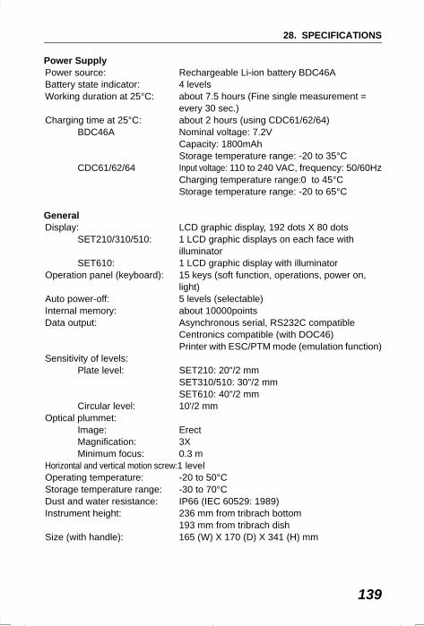
139
28. SPECIFICATIONS
Power SupplyPower source: Rechargeable Li-ion battery BDC46ABattery state indicator: 4 levelsWorking duration at 25°C: about 7.5 hours (Fine single measurement =
every 30 sec.)Charging time at 25°C: about 2 hours (using CDC61/62/64)
BDC46A Nominal voltage: 7.2VCapacity: 1800mAhStorage temperature range: -20 to 35°C
CDC61/62/64 Input voltage: 110 to 240 VAC, frequency: 50/60HzCharging temperature range:0 to 45°CStorage temperature range: -20 to 65°C
GeneralDisplay: LCD graphic display, 192 dots X 80 dots
SET210/310/510: 1 LCD graphic displays on each face with illuminator
SET610: 1 LCD graphic display with illuminatorOperation panel (keyboard): 15 keys (soft function, operations, power on,
light) Auto power-off: 5 levels (selectable)Internal memory: about 10000pointsData output: Asynchronous serial, RS232C compatible
Centronics compatible (with DOC46) Printer with ESC/PTM mode (emulation function)
Sensitivity of levels:Plate level: SET210: 20"/2 mm
SET310/510: 30"/2 mmSET610: 40"/2 mm
Circular level: 10'/2 mmOptical plummet:
Image: ErectMagnification: 3XMinimum focus: 0.3 m
Horizontal and vertical motion screw:1 levelOperating temperature: -20 to 50°CStorage temperature range: -30 to 70°CDust and water resistance: IP66 (IEC 60529: 1989)Instrument height: 236 mm from tribrach bottom
193 mm from tribrach dishSize (with handle): 165 (W) X 170 (D) X 341 (H) mm
SET310_28.fm 139 ページ 2002年6月25日 火曜日 午前11時18分
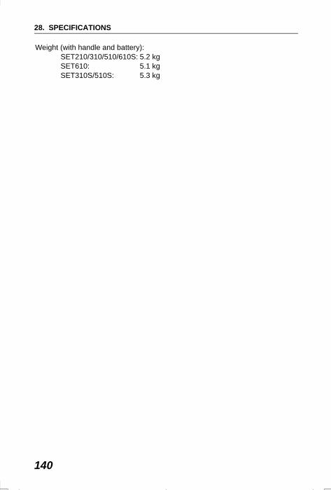
28. SPECIFICATIONS
140
Weight (with handle and battery):SET210/310/510/610S: 5.2 kgSET610: 5.1 kgSET310S/510S: 5.3 kg
SET310_28.fm 140 ページ 2002年6月25日 火曜日 午前11時18分
141
29.REGULATIONSRadio Frequency Interference
WARNING: Changes or modifications to this unit not expressly approved by the party responsible for compliance could void the user's authority to operate the equipment.
NOTE: This equipment has been tested and found to comply with the limits for a Class A digital device pursuant to Part 15 of the FCC Rules. These limits are designed to provide reasonable protection against harmful inter-ference when the equipment is operated in a commercial environment. This equipment generates, uses, and can radiate radio frequency energy and, if not installed and used in accordance with the instruction manual, may cause harmful interference to radio communications. Operation of this equipment in a residential area is likely to cause harmful interference in which case the user will be required to correct the interference at his own expense.
Notice for CanadaThis Class A digital apparatus meets all requirements of Canadian Interference-Causing Equipment Regulations.Cet appareil numérique de la Class A respecte toutes les exigences du Règlement sur le matériel brouilleur du Canada.
SET310_29.fm 141 ページ 2002年2月15日 金曜日 午前9時8分
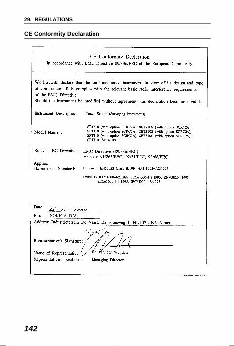
29. REGULATIONS
142
CE Conformity Declaration
SET310_29.fm 142 ページ 2002年6月25日 火曜日 午前10時54分
143
29. REGULATIONS
SET310_29.fm 143 ページ 2002年2月15日 金曜日 午前9時8分
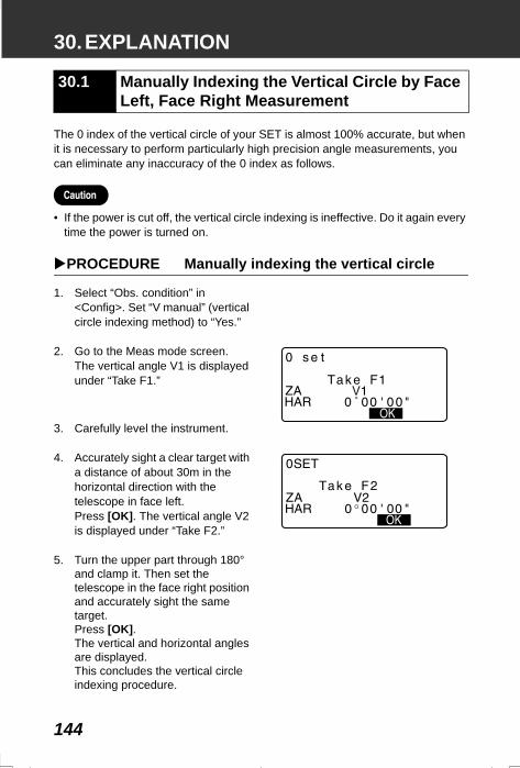
144
30.EXPLANATION
The 0 index of the vertical circle of your SET is almost 100% accurate, but when it is necessary to perform particularly high precision angle measurements, you can eliminate any inaccuracy of the 0 index as follows.
• If the power is cut off, the vertical circle indexing is ineffective. Do it again every time the power is turned on.
PROCEDURE Manually indexing the vertical circle
1. Select “Obs. condition” in <Config>. Set “V manual” (vertical circle indexing method) to “Yes.”
2. Go to the Meas mode screen. The vertical angle V1 is displayed under “Take F1.”
3. Carefully level the instrument.
4. Accurately sight a clear target with a distance of about 30m in the horizontal direction with the telescope in face left.Press [OK]. The vertical angle V2 is displayed under “Take F2.”
5. Turn the upper part through 180° and clamp it. Then set the telescope in the face right position and accurately sight the same target.Press [OK].The vertical and horizontal angles are displayed. This concludes the vertical circle indexing procedure.
30.1 Manually Indexing the Vertical Circle by Face Left, Face Right Measurement
SET310_30.fm 144 ページ 2002年2月15日 金曜日 午前9時8分

SET310_C3C4.fm 1 ページ 2002年5月17日 金曜日 午後6時43分

4th ed. 05-0208 Printed in Japan ©2001 SOKKIA CO., LTD.
SET310_C3C4.fm 2 ページ 2002年8月22日 木曜日 午前9時30分


![Diesel Operator's Manual Spanish[1]](https://img.pdfslide.tips/doc/110x75/557201044979599169a09078/diesel-operators-manual-spanish1.jpg)