Embed Size (px)
DESCRIPTION
LC3 Simulator tutorial!
Citation preview
LC-3 and LC-3bSimulator TutorialSimulator Tutorial
No minors!
All breakpoints used in this tutorial are 18 years of age or older.
© 2003 Ashley Wise
Preamble
• The LC-3/LC-3b toolset is open to enhancements. Please send any bug reports, suggestions, or comments to Ashley:– [email protected]
– Put "LC-3/lC-3b Simulator" in the subject so it doesn't get filtered – Put "LC-3/lC-3b Simulator" in the subject so it doesn't get filtered as spam.
– Nit-picking is good.
• This tutorial is for Simulator version 1. Simulator version 1 uses Assembler versions 3.
Simulator Topics
• Running the Simulator• Simulator Basics• General Commands• Stepping Through Instructions/Cycles/Subroutines• Stepping Through Instructions/Cycles/Subroutines• Viewing Instructions, Data, Memory, Byte Arrays, and
Registers• Displaying Simulation Information• Setting Instruction, Data, Memory, and Register
Breakpoints• Advanced Topics
Simulator Topics
• Advanced Topics– Editing Instructions, Data, Registers, and Memory During
Simulation– Tracing Instruction Execution and Registers– Runtime Error Checking, Exceptions, and Interrupts– Runtime Error Checking, Exceptions, and Interrupts– Simulation State - Saving/Loading– Memory Images - Saving/Loading– Program Objects - Saving/Loading– Multiple Program Simulating– Console and Memory-Mapped I/O– Ash Operating System– Modifying the Architecture
Running The Simulator
• Download the archive– LC3[b]Simulator.zip
• Extract the archive– Use WinZip, etc., on Windows– And on Unix:
> unzip LC3[b]Simulator.zip
• Set execute permissions for Unix> chmod u+x LC3[b]Simulator
Running The Simulator
• Execute at the command line by entering the name of the extracted simulator followed by a list of assembly file names and command line parameters.> LC3[b]Simulator Sample.asm OS.asm -s
• If you want to type a smaller name, or automatically use certain options (such as -s), create a shell script (a sample script, "sim", is provided):LC3[b]Simulator -s $*
– Then just enter:> sim Sample.asm OS.asm
Command Line Options
• The simulator takes any number of assembly file names as parameters. Each file represents one program. All of the programs will be assembled together and then simulated.
• Options (case insensitive)– The assembler is run on the files before they are passed to the – The assembler is run on the files before they are passed to the
simulator. All necessary assembler options should be specified as options to the simulator.
– -sim• Runs the Simulator on the input program(s). It is not necessary to
specify this option.– -os
• Links the Ash Operating System with the program. See the Ash Operating System section.
LC-3 Translator
• In order to support older LC-3 assembler syntax, a translator is run on the input assembly files before compilation in the LC3Simulator.
• The translation is completely transparent to the user. The user can use older LC-3 syntax files in the simulator user can use older LC-3 syntax files in the simulator without knowledge of the internal translation.
• The translation does not apply to the LC3bSimulator.• The LC-3 translator is also applied to simulator command
strings. This allows the use of the "x", "b", "#" syntax for numbers, as well as the use of .FILL, .BLKW, and .STRINGZ in write data commands.
• See the Assembler Tutorial's LC-3 translator section for more information.
Simulator Basics
• Simulator 1 has Assembler 3 built into the executable. The simulator uses the symbolic program created by the assembler to provide a wider range of more powerful debugging and simulation features.– See the Assembler Tutorial and related documentation.– See the Assembler Tutorial and related documentation.
• The simulator only runs upon successful compilation and linking of the input assembly (or disassembled image) programs.
• On a P4 2.4GHz, the simulator executes >45,000 instructions per second (>50,000 with checks off, >20,000 with instruction and register tracing).
Simulator Basics
• The simulator is both an architectural and software simulator– It provides file-, line number-, and code-level simulation of input
assembly files using step-through- and breakpoint-based debugging methodologies. All the main features of MSVC and debugging methodologies. All the main features of MSVC and GDB are present, as well as many new ones.
– It provides cycle-level microarchitecture simulation and full access to all registers and memory arrays. New architectures can be easily programmed in.
– Only the default architecture is exampled in the tutorial. This includes the RegFile, Control, and MMIO register sets and the DRAM memory array. All instructions are executed in exactly one cycle.
Simulator Basics
• Logical Data– Logical data is data from the point of view of the assembly
program. Everything is in one flat address space.– Logical data can be accessed during simulation using addresses,
symbols, structure member and array index access and attributes symbols, structure member and array index access and attributes using Assembler 3 syntax.
– Logical data is interpreted as the datatype it was defined as in the assembly program.
• Physical Memory– Logical data may be located in any number of physical memory
arrays (i.e. in a cache hierarchy).– Memory data is interpreted as byte data unless otherwise specified.– For the default architecture, the DRAM physical memory is
equivalent to the logical memory space.
Simulator Basics
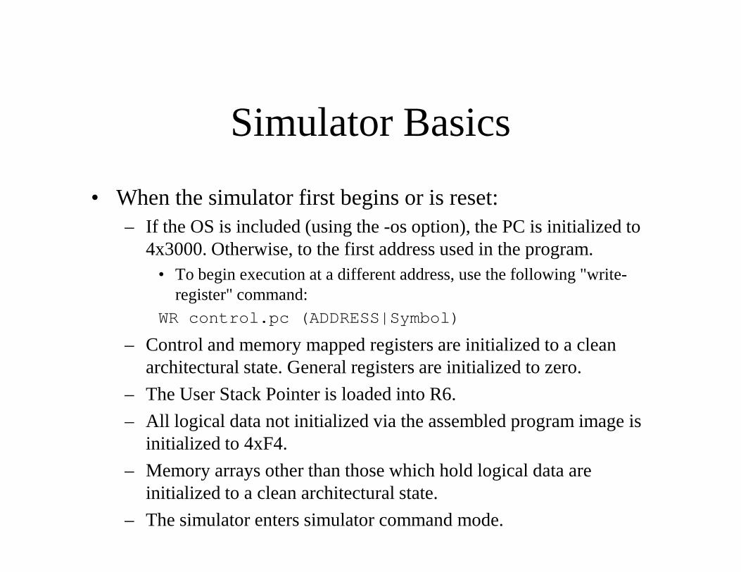
• When the simulator first begins or is reset:– If the OS is included (using the -os option), the PC is initialized to
4x3000. Otherwise, to the first address used in the program.• To begin execution at a different address, use the following "write-
register" command:register" command:WR control.pc (ADDRESS|Symbol)
– Control and memory mapped registers are initialized to a clean architectural state. General registers are initialized to zero.
– The User Stack Pointer is loaded into R6.
– All logical data not initialized via the assembled program image is initialized to 4xF4.
– Memory arrays other than those which hold logical data are initialized to a clean architectural state.
– The simulator enters simulator command mode.
Simulator Basics
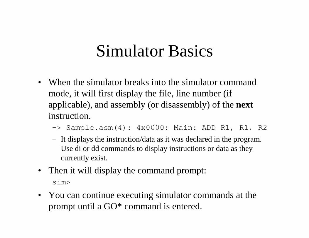
• When the simulator breaks into the simulator command mode, it will first display the file, line number (if applicable), and assembly (or disassembly) of the nextinstruction.instruction.-> Sample.asm(4): 4x0000: Main: ADD R1, R1, R2
– It displays the instruction/data as it was declared in the program. Use di or dd commands to display instructions or data as they currently exist.
• Then it will display the command prompt:sim>
• You can continue executing simulator commands at the prompt until a GO* command is entered.
Simulator Basics
• All of the GO* commands will exit the simulator command mode and resume simulator execution mode. The simulator will break back into the simulator command mode when a breakpoint or other break condition is reached.reached.
• All simulator commands are case-insensitive.• All simulator tokens (numbers, symbols, etc) follow
Assembler 3 syntax.– Numbers can be of any integral, real, or character syntax.– Symbols can use struct member and array index access and
attributes.
General Commands
CTRL-C– Pauses execution and breaks into simulator command mode.
RESET– Reinitialize the simulator architecture (registers and memories) and
reload the original program image into the logical memory.reload the original program image into the logical memory.
CONSOLE Number– Sets the console width to the specified number. Assembler and
simulator messages are smart-wrapped at the console width. The default is 80 characters.
PRINTI Number Number– Sets the pre- and post-instruction counts. When the current
instruction is displayed, the specified number of adjacent instructions are printed before and after it. The default is 5 and 10.
General Commands
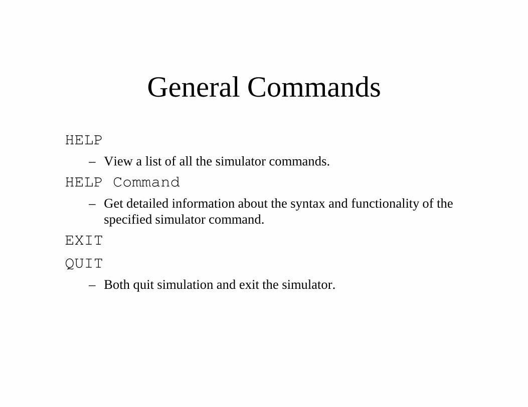
HELP
– View a list of all the simulator commands.
HELP Command
– Get detailed information about the syntax and functionality of the – Get detailed information about the syntax and functionality of the specified simulator command.
EXIT
QUIT
– Both quit simulation and exit the simulator.
Stepping Through
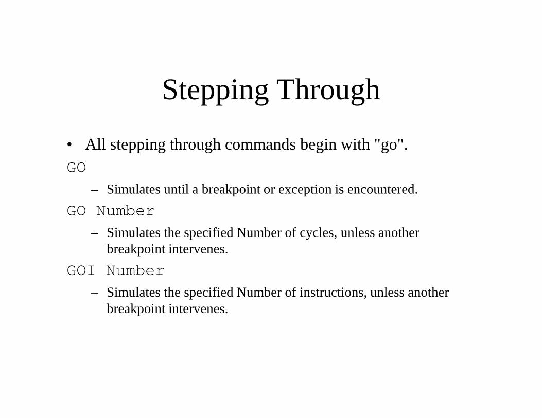
• All stepping through commands begin with "go".GO
– Simulates until a breakpoint or exception is encountered.
GO NumberGO Number
– Simulates the specified Number of cycles, unless another breakpoint intervenes.
GOI Number
– Simulates the specified Number of instructions, unless another breakpoint intervenes.
Stepping Through
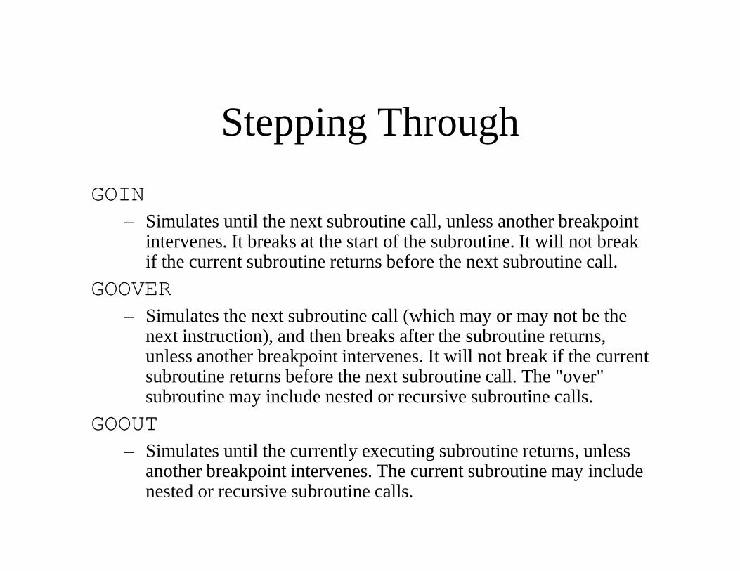
GOIN– Simulates until the next subroutine call, unless another breakpoint
intervenes. It breaks at the start of the subroutine. It will not break if the current subroutine returns before the next subroutine call.
GOOVERGOOVER– Simulates the next subroutine call (which may or may not be the
next instruction), and then breaks after the subroutine returns, unless another breakpoint intervenes. It will not break if the current subroutine returns before the next subroutine call. The "over" subroutine may include nested or recursive subroutine calls.
GOOUT– Simulates until the currently executing subroutine returns, unless
another breakpoint intervenes. The current subroutine may include nested or recursive subroutine calls.
Stepping Through
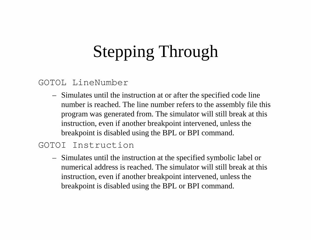
GOTOL LineNumber
– Simulates until the instruction at or after the specified code line number is reached. The line number refers to the assembly file this program was generated from. The simulator will still break at this instruction, even if another breakpoint intervened, unless the instruction, even if another breakpoint intervened, unless the breakpoint is disabled using the BPL or BPI command.
GOTOI Instruction
– Simulates until the instruction at the specified symbolic label or numerical address is reached. The simulator will still break at this instruction, even if another breakpoint intervened, unless the breakpoint is disabled using the BPL or BPI command.
Viewing Instructions
• All display commands begin with "d".DIL LineNumber [Length]
DI Data [Length]
– Displays the specified number of instructions at the specified code – Displays the specified number of instructions at the specified code line number or logical data location (symbolic label or numerical address). The address, file location, and any label pointing to this instruction is also displayed. Even if the data was not declared as an instruction, it will be disassembled and displayed as an instruction. If length is not specified, only one instruction is displayed. ('[*]' means optional, and is not part of the syntax).
Viewing Data
DL LineNumber [Length]– Displays the specified number of data elements at the specified
code line number. The simulator will use the program to determine the datatype for display. The address of the data is also displayed. Data is displayed in both hex and decimal. If Data points to an Data is displayed in both hex and decimal. If Data points to an instruction, then the disassembled instruction is displayed. If length is not specified, only one data element is displayed.
DL LineNumber [-]DataType [Length]– Displays the data as the specified datatype (the assembler
keywords DATA1-8 and REAL1-8). Integral data is interpreted as unsigned unless the '-' operator is specified. ('[*]' means optional, and is not part of the syntax).
Viewing Data
DD Data [Length]– Displays the specified number of data elements at the specified
logical data location (symbolic label or numerical address). The simulator will use the program to determine the datatype for display. The address of the data is also displayed. Data is displayed display. The address of the data is also displayed. Data is displayed in both hex and decimal. If Data points to an instruction, then the disassembled instruction is displayed. If length is not specified, only one data element is displayed.
DD Data [-]DataType [Length]– Displays the data as the specified datatype (the assembler
keywords DATA1-8 and REAL1-8). Integral data is interpreted as unsigned unless the '-' operator is specified. ('[*]' means optional, and is not part of the syntax).
Viewing Memory
DM– Displays the names of all the architectural memories. "dram" is the
only memory in the default architecture.DM MemoryName ByteAddress [[-]DataType][Length][Length]– Displays the specified number of data elements at the specified
memory location (symbolic label or numerical address). The address is also displayed. Data is displayed in both hex and decimal. The data is interpreted as the specified datatype (the assembler keywords DATA1-8 and REAL1-8), or word data (LC-3) or byte data (LC-3b) if datatype is not provided. Integral data is interpreted as unsigned unless the '-' operator is specified. ('[*]' means optional, and is not part of the syntax).
• The resulting address obtained from a label used for a memory array may not correspond to the desired logical data location.
• In the case of "dram" though, the logical and physical addresses are equivalent, so symbolic addresses can be safely used.
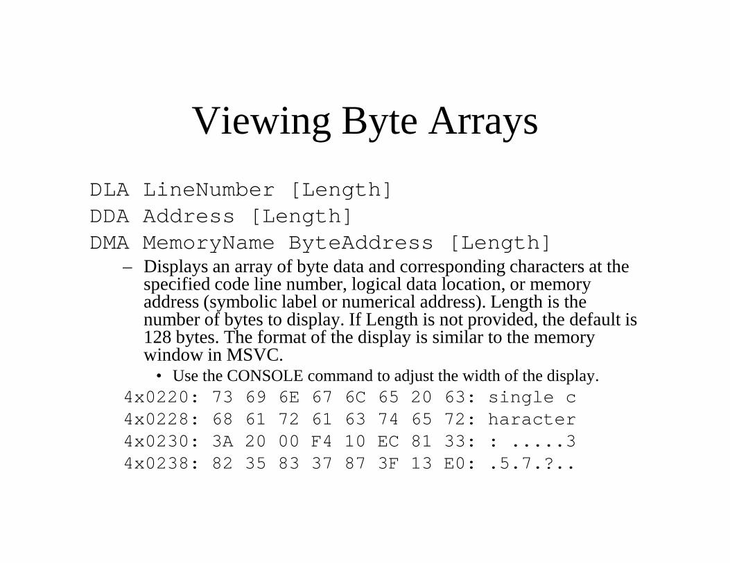
Viewing Byte Arrays
DLA LineNumber [Length]DDA Address [Length]DMA MemoryName ByteAddress [Length]
– Displays an array of byte data and corresponding characters at the specified code line number, logical data location, or memory specified code line number, logical data location, or memory address (symbolic label or numerical address). Length is the number of bytes to display. If Length is not provided, the default is 128 bytes. The format of the display is similar to the memory window in MSVC.
• Use the CONSOLE command to adjust the width of the display.4x0220: 73 69 6E 67 6C 65 20 63: single c4x0228: 68 61 72 61 63 74 65 72: haracter4x0230: 3A 20 00 F4 10 EC 81 33: : .....34x0238: 82 35 83 37 87 3F 13 E0: .5.7.?..
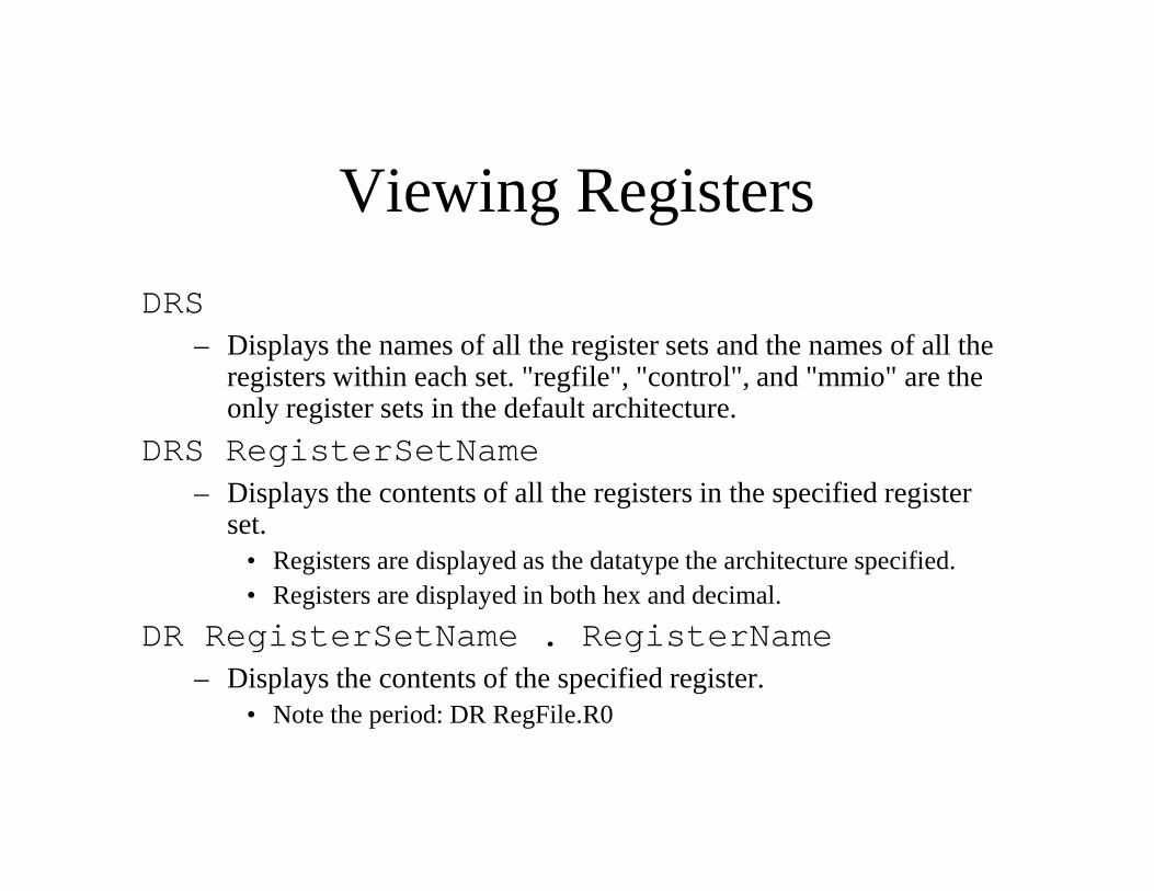
Viewing Registers
DRS– Displays the names of all the register sets and the names of all the
registers within each set. "regfile", "control", and "mmio" are the only register sets in the default architecture.
DRS RegisterSetNameDRS RegisterSetName– Displays the contents of all the registers in the specified register
set.• Registers are displayed as the datatype the architecture specified.• Registers are displayed in both hex and decimal.
DR RegisterSetName . RegisterName– Displays the contents of the specified register.
• Note the period: DR RegFile.R0
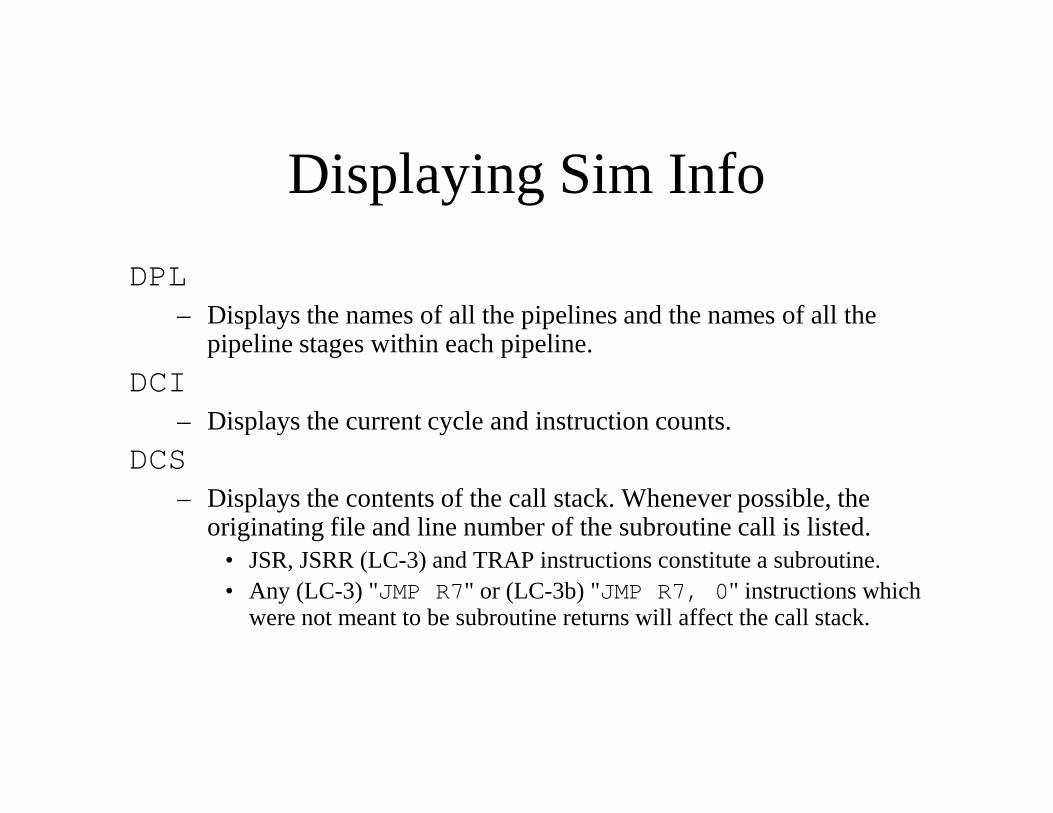
Displaying Sim Info
DPL– Displays the names of all the pipelines and the names of all the
pipeline stages within each pipeline.
DCI– Displays the current cycle and instruction counts.– Displays the current cycle and instruction counts.
DCS– Displays the contents of the call stack. Whenever possible, the
originating file and line number of the subroutine call is listed.• JSR, JSRR (LC-3) and TRAP instructions constitute a subroutine.• Any (LC-3) "JMP R7" or (LC-3b) "JMP R7, 0" instructions which
were not meant to be subroutine returns will affect the call stack.
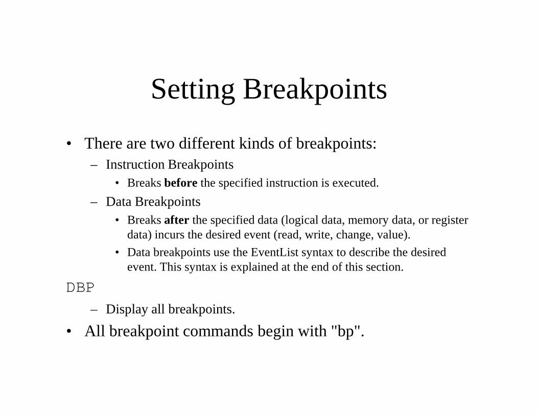
Setting Breakpoints
• There are two different kinds of breakpoints:– Instruction Breakpoints
• Breaks before the specified instruction is executed.
– Data Breakpoints– Data Breakpoints• Breaks after the specified data (logical data, memory data, or register
data) incurs the desired event (read, write, change, value).
• Data breakpoints use the EventList syntax to describe the desired event. This syntax is explained at the end of this section.
DBP
– Display all breakpoints.
• All breakpoint commands begin with "bp".
Instruction Breakpoints
BPL LineNumber
– Sets a breakpoint for the instruction at or after the given code line number. The line number refers to the assembly file this program was generated from.
BPI Instruction
– Sets a breakpoint for the instruction at the specified symbolic label or numerical address.
BPL LineNumber NoEvent
BLI Instruction NoEvent
– Removes the specified breakpoint
BPIC
– Clears all instruction, line, and goto breakpoints.
Instruction Breakpoints
GOTOL/GOTOI
– These were already discussed in the Stepping Through section. These are similar to regular instruction breakpoints except that they resume simulation when entered, and they are temporary breakpoints. After they break once, they are removed, unless an breakpoints. After they break once, they are removed, unless an explicit BPL or BPI to the same instruction is used to override the goto.
Data Breakpoints
BPD Data EventList
– Sets a breakpoint for the specified logical data location (symbolic label or numerical address). See the EventList section for info on the other parameters.
BPDC
– Clears all data breakpoints.
Memory Breakpoints
BPM MemoryName ByteAddress EventList
– Sets a breakpoint for the specified memory address (symbolic label or numerical address). See the EventList section for info on the other parameters. See the DM command to get the memory names.
• The resulting address obtained from a label used for a memory array may not correspond to the desired logical data location.
• In the case of "dram" though, the logical and physical addresses are equivalent, so symbolic addresses can be safely used
BPMC
– Clears all memory breakpoints.
Register Breakpoints
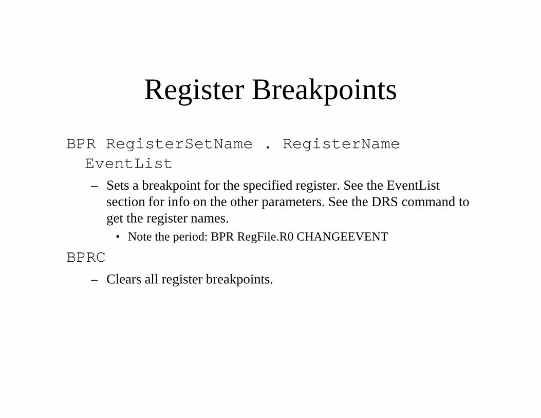
BPR RegisterSetName . RegisterNameEventList
– Sets a breakpoint for the specified register. See the EventList section for info on the other parameters. See the DRS command to get the register names.
• Note the period: BPR RegFile.R0 CHANGEEVENT
BPRC
– Clears all register breakpoints.
Breakpoint EventList
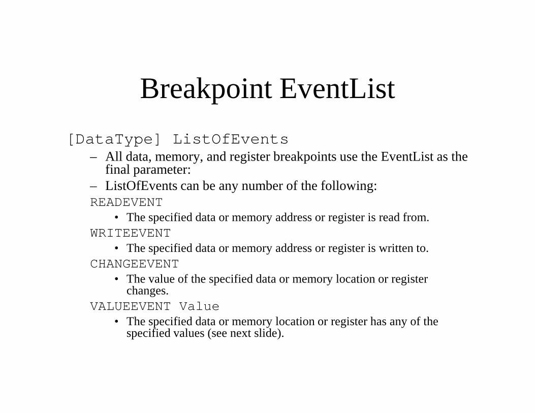
[DataType] ListOfEvents– All data, memory, and register breakpoints use the EventList as the
final parameter:– ListOfEvents can be any number of the following:READEVENTREADEVENT
• The specified data or memory address or register is read from.WRITEEVENT
• The specified data or memory address or register is written to.CHANGEEVENT
• The value of the specified data or memory location or register changes.
VALUEEVENT Value• The specified data or memory location or register has any of the
specified values (see next slide).
Breakpoint EventList
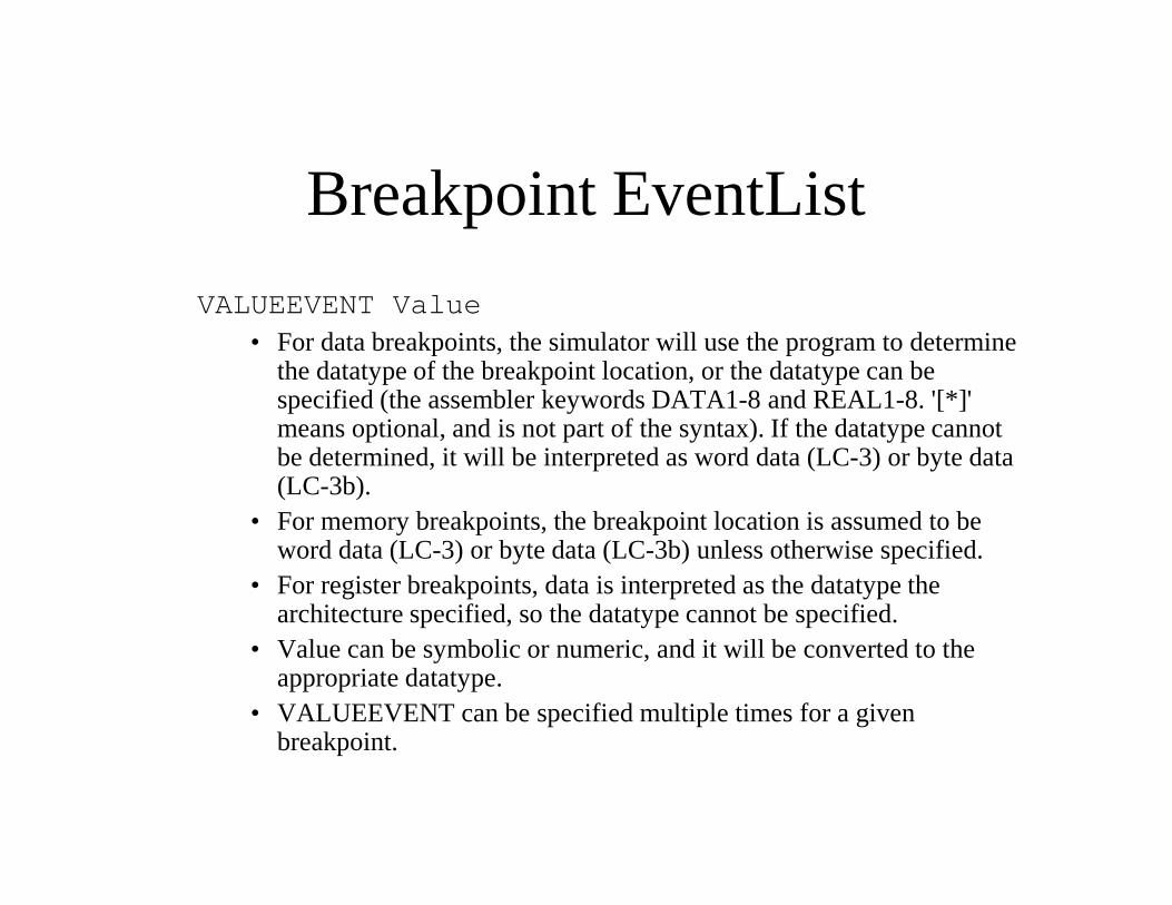
VALUEEVENT Value• For data breakpoints, the simulator will use the program to determine
the datatype of the breakpoint location, or the datatype can be specified (the assembler keywords DATA1-8 and REAL1-8. '[*]' means optional, and is not part of the syntax). If the datatype cannot be determined, it will be interpreted as word data (LC-3) or byte data be determined, it will be interpreted as word data (LC-3) or byte data (LC-3b).
• For memory breakpoints, the breakpoint location is assumed to be word data (LC-3) or byte data (LC-3b) unless otherwise specified.
• For register breakpoints, data is interpreted as the datatype the architecture specified, so the datatype cannot be specified.
• Value can be symbolic or numeric, and it will be converted to the appropriate datatype.
• VALUEEVENT can be specified multiple times for a given breakpoint.
Breakpoint EventList
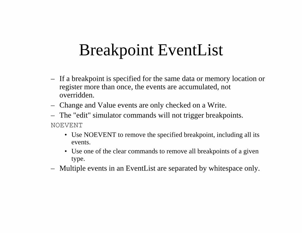
– If a breakpoint is specified for the same data or memory location or register more than once, the events are accumulated, not overridden.
– Change and Value events are only checked on a Write.– The "edit" simulator commands will not trigger breakpoints.– The "edit" simulator commands will not trigger breakpoints.NOEVENT
• Use NOEVENT to remove the specified breakpoint, including all its events.
• Use one of the clear commands to remove all breakpoints of a given type.
– Multiple events in an EventList are separated by whitespace only.
Editing Data
• All editing (write) commands begin with "w".• Editing data allows for limited "edit and continue"
functionality.– Limited because you can only overwrite, and not insert.
• To save and restore edits, see the section on saving and • To save and restore edits, see the section on saving and loading memory images.
Editing Instructions & Data
WL LineNumber ElementList– Write the elements into the logical data location at or after the
specified code line number. Data already at that location will be overwritten. Changes due to this write are lost on reset and do not affect the original program.
– The element list can consist of any number of data, struct, and – The element list can consist of any number of data, struct, and instruction elements as defined in the Assembler documentation. Symbols can be used within the elements.
– Example: Edit an instruction and subsequent data at line 15:WL 15 BRnz Loop DATA2 5• The above is assembled into a 4-byte memory image.
WD Data ElementList– Write the elements into the specified logical data location
(symbolic label or numerical address).– Otherwise identical to WL.
Editing Memory
WM MemoryName ByteAddress ElementList
– Write the elements into the specified memory address (symbolic label or numerical address). See the DM command to get the memory names.
– The element list is the same as described for the WL command.
Editing Registers
WR RegisterSetName . RegisterName Value
– Write the value into the specified register. See the DRS command to get the register names.
– Value can be symbolic or numeric.
Tracing Execution
TRACEON "FileName" [ListOfRegisterSets]– Turns on a trace of the dynamically executing instructions.– The filename must be enclosed in quotes.– If a list of register set names is provided (each name separated by
whitespace only. '[*]' means optional, and is not part of the whitespace only. '[*]' means optional, and is not part of the syntax), then the contents of those register sets will also be traced.
– The format of the trace file is (one line per instruction executed):• Cycle;\tInstruction;\tLocation,\tOpcode,\tOperands;\t
FirstRegisterSet\tFirstRegister: 4xHex (Dec),\tSecondRegister...etc;\tSecondRegisterSet...etc\n
• The file can be opened in Excel (tab-delimited spreadsheet).• Whenever possible, the file(linenumber) is included in "Location",
along with the address and a possible label.• The instruction in the trace file is the next instruction to be executed,
and the register values are the values before this instruction is executed.
Tracing Execution
TRACEOFF
– Turns off the trace and closes the file.
– When tracing is on, the performance of the simulator is reduced by approximately 60%.
Runtime Error Checking
CHECKON– Enables certain runtime checking of the program execution which
may detect possible program or architectural errors. Check violations will create warning messages and will break into simulator command mode. Typing GO will resume simulation.simulator command mode. Typing GO will resume simulation.
– Example violations:• PC addresses which do not correspond to programmed instruction
elements• Infinite subroutine recursion• Unmatched subroutine returns
– Runtime checking is disabled by default.
CHECKOFF– Disables runtime checking.– When checking is off, the performance of the simulator increases
by 20%.
Runtime Exceptions
• Exceptions will create warning messages and will break into simulator command mode. Typing GO will resume simulation.
• Exceptions are raised by the processor architecture.• Exceptions are raised by the processor architecture.
• Example exceptions:– Invalid instruction/opcode.
– Privilege mode violation.
– Misaligned memory access.
– Program clock stopped (via the MCR memory-mapped IO register).
Runtime Interrupts
INT Value– Sends an external interrupt to the processor. You can
use a label into the interrupt vector table or an interrupt number.
– LC-3 (LC-3b) defines interrupt vectors 4x80 (4x40) – LC-3 (LC-3b) defines interrupt vectors 4x80 (4x40) through 4xFF (4x7F), which reside at word (byte) addresses 4x180 through 4x1FF.
– The only interrupt defined is the keyboard interrupt, vector 4x80 (4x40). The Interrupt Enable (IE) bit is KBSR bit 0 (see the Memory-Mapped I/O section), which defaults to enabled.
– Interrupts are queued until they are processed.
Simulation State
SAVES "FileName"– Saves the state of the simulation.– The filename must be enclosed in quotes, and does not need an
extension.– All of the memories will be saved to FileName.Mem.Name.bin.– All of the memories will be saved to FileName.Mem.Name.bin.– All of the register sets will be saved to
FileName.RegSet.Name.bin.– Any architecture state which is not in registers is saved to
FileName.Arch.bin.– Any required simulator data is saved to FileName.Sim.bin.– Breakpoints are not saved.
LOADS "FileName"– Loads the state of the simulation from a previous save.
Memory Images
SAVED "FileName" Address Length [[-] DataType]– Saves a logical data image beginning at Address for Length
number of data elements (symbolic or numeric) to the specified binary file. binary file.
– The filename must be enclosed in quotes.– If a datatype is specified (the assembler keywords DATA1-8 and
REAL1-8), it interprets the data as elements of that datatype, otherwise word data (LC-3) or byte data (LC-3b). ('[*]' means optional, and is not part of the syntax).
– If the minus sign is provided, it indicates to save the data in the opposite endian-ness as the ISA, otherwise the same endian-ness as the ISA.
– The resulting file can be opened in an image editor as a raw type, or a text editor.
Memory Images
LOADD "FileName" Address Length [[-] DataType]– Loads a logical data image beginning at Address for Length
number of data elements (symbolic or numeric) from the specified binary file.
– The filename must be enclosed in quotes.– The filename must be enclosed in quotes.– If a datatype is specified (the assembler keywords DATA1-8 and
REAL1-8), it interprets the data as elements of that datatype, otherwise word data (LC-3) or byte data (LC-3b). ('[*]' means optional, and is not part of the syntax).
– If the minus sign is provided, it indicates to load the data in the opposite endian-ness as the ISA, otherwise the same endian-ness as the ISA.
– A raw image (no header) from a paint program, or a text file, can be loaded.
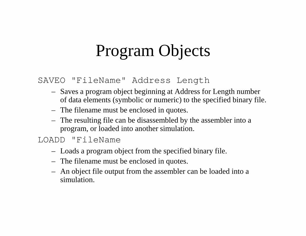
Program Objects
SAVEO "FileName" Address Length– Saves a program object beginning at Address for Length number
of data elements (symbolic or numeric) to the specified binary file. – The filename must be enclosed in quotes.– The resulting file can be disassembled by the assembler into a – The resulting file can be disassembled by the assembler into a
program, or loaded into another simulation.
LOADD "FileName– Loads a program object from the specified binary file.– The filename must be enclosed in quotes.– An object file output from the assembler can be loaded into a
simulation.
Multiple Program Simulating
• If multiple programs (assembly or disassembled files) were linked together to create the simulated memory image, then line numbers and symbols used in simulator commands may be ambiguous.may be ambiguous.
• The simulator will guess which program to use for line numbers and symbols. (For instance, the first program which defines the symbol will be used to resolve it.)
• A program number can be specified in the simulator command to explicitly tell the simulator which program to use for the command's line numbers and symbols.
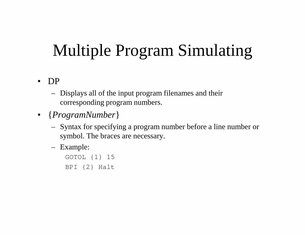
Multiple Program Simulating
• DP– Displays all of the input program filenames and their
corresponding program numbers.
• { ProgramNumber}• { ProgramNumber}– Syntax for specifying a program number before a line number or
symbol. The braces are necessary.
– Example:GOTOL {1} 15
BPI {2} Halt
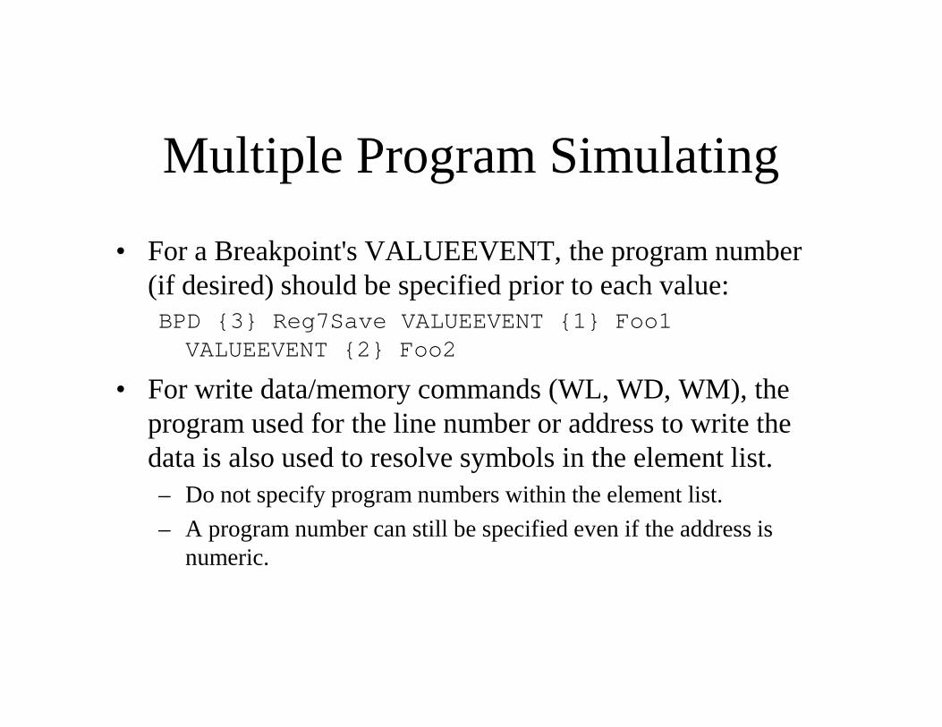
Multiple Program Simulating
• For a Breakpoint's VALUEEVENT, the program number (if desired) should be specified prior to each value:BPD {3} Reg7Save VALUEEVENT {1} Foo1 VALUEEVENT {2} Foo2
• For write data/memory commands (WL, WD, WM), the program used for the line number or address to write the data is also used to resolve symbols in the element list.– Do not specify program numbers within the element list.
– A program number can still be specified even if the address is numeric.
Memory-Mapped IO
• The LC-3 and IC-3b ISAs defines several addresses for memory-mapped IO.
• Any read or write to these addresses (even indirectly as part of the secondary memory access in an LDI, RTI, etc) part of the secondary memory access in an LDI, RTI, etc) will access the register.
• In the default architecture, all memory-mapped registers are available in the "mmio" register set.
Memory-Mapped I/O
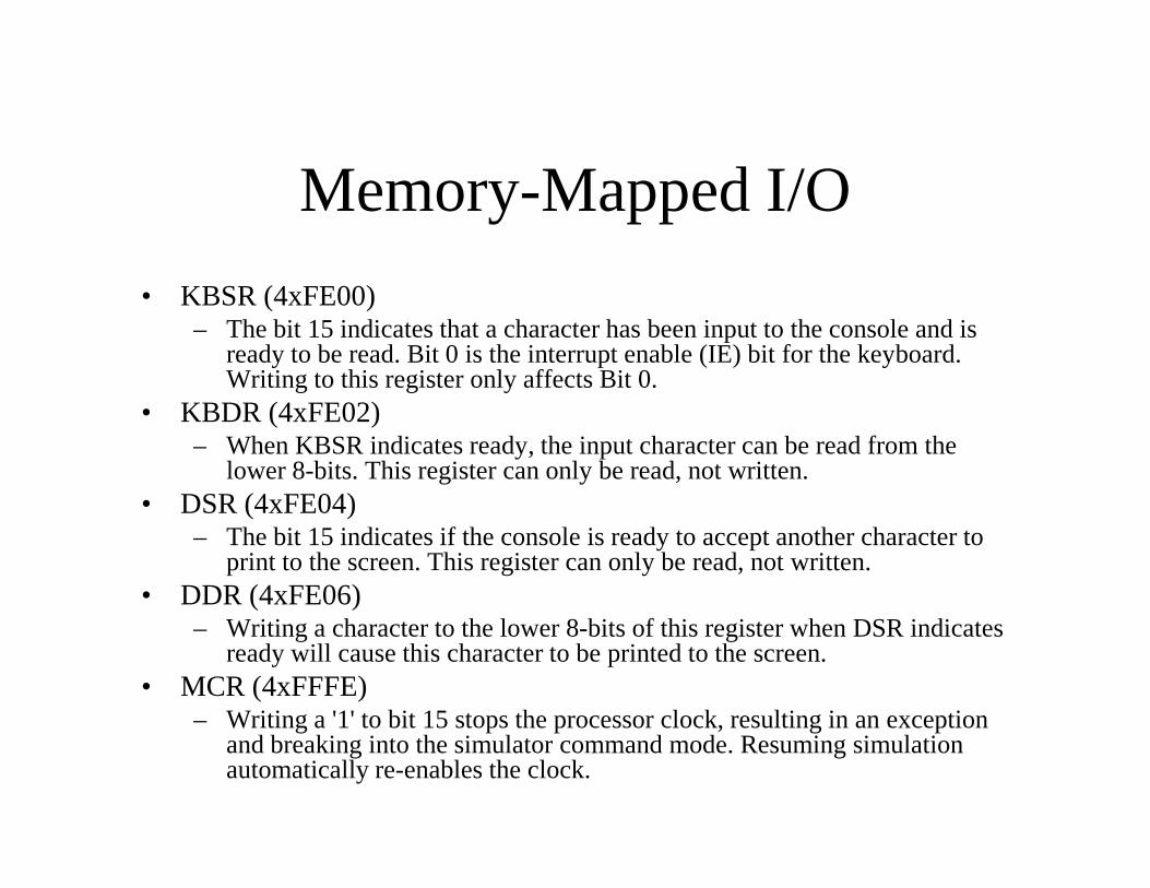
• KBSR (4xFE00)– The bit 15 indicates that a character has been input to the console and is
ready to be read. Bit 0 is the interrupt enable (IE) bit for the keyboard. Writing to this register only affects Bit 0.
• KBDR (4xFE02)– When KBSR indicates ready, the input character can be read from the – When KBSR indicates ready, the input character can be read from the
lower 8-bits. This register can only be read, not written.• DSR (4xFE04)
– The bit 15 indicates if the console is ready to accept another character to print to the screen. This register can only be read, not written.
• DDR (4xFE06)– Writing a character to the lower 8-bits of this register when DSR indicates
ready will cause this character to be printed to the screen.• MCR (4xFFFE)
– Writing a '1' to bit 15 stops the processor clock, resulting in an exception and breaking into the simulator command mode. Resuming simulation automatically re-enables the clock.
Console I/O
• The simulator console is always ready to accept a character. When a character is given to DDR, the simulator gives the following prompt:<Simulating program outputting characters><Simulating program outputting characters>
– This is followed by all the characters output by the program. The prompt is only displayed again if another simulator message intervenes.
Console I/O
• When KBSR is read, the simulator gives the following prompt:<Simulating program requests # characters>
– If characters are entered, then they are placed in KBDR and KBSR bit 15 is set.bit 15 is set.
– If no characters are entered, then KBSR bit 15 is not set.– If more characters are given than are requested, the characters are
stored for subsequent requests.• The MMIO register only knows to request one character at a time, so
the prompt is displayed for each requested character.• Whole lines can be input at once by typing everything at the first
prompt. Subsequent requests will then take from the extra input.• The extra input is discarded if the simulator breaks into command
mode.
Console I/O
– CTRL-D, not ENTER, is used to indicate the end of input. All characters after CTRL-D are ignored.
• This allows a newline to be a valid input character.• CTRL-D as the first or only input signals no input ready.• Windows requires an ENTER after CTRL-D to submit console input; • Windows requires an ENTER after CTRL-D to submit console input;
some Unix and Linux consoles do not.
– CTRL-C is used to indicate error.• All input after the last enter is ignored, -1 is stored in KBDR.• An ENTER is not required.
– CTRL-Z is used to indicate EOF (end-of-file).• On windows, all characters after CTRL-Z are ignored, and -1 is stored
in KBDR.• On Unix and Linux, CTRL-Z suspends the process and should not be
used.
Ash Operating System
• The AshOS operating system is included with the simulator in both LC-3 and LC-3b incarnations. An operating system is not required in order to simulate a program, and any OS can be created and used in place of AshOS.AshOS.– AshOS_LC3[b].asm is automatically linked with the user program
when the -os option is used.– AshOS_LC3[b].ah can be included in the user program's assembly
file. (See the Assembler INCLUDE directive). This allows you to use the OS's function labels (i.e., you can do "trap GETC" instead of "trap 4x20").
– The OS files are assumed to be in the current directory. If not, you'll be prompted to enter the location.
Ash Operating System
• The AshOS.ah header includes DEFINE statements for the addresses of the MMIO registers.
• The AshOS.ah header also includes EXTERN declarations for the OS functions.
• OS functions must be called using TRAP.– R0 is used to transfer data between the user code and OS functions.– (LC-3b only) R6 is not preserved (a limitation in the ISA).– R7 is overwritten by the TRAP instruction.– All other registers are preserved.
• If the OS is included, execution of user code begins at address 4x3000.
Ash Operating System
• The following OS functions are implemented:– GETC
• Reads a single character from the keyboard. The character is not echoed onto the console. The character is returned in R0.
– OUT– OUT• Write the character in R0[7:0] to the console
– IN• Print a prompt to the screen and read a single character from the
keyboard. The character is echoed onto the console along with a newline. The character is returned in R0.
– HALT• Halt execution and print a message to the console.
Ash Operating System
– PUTS• Write the string pointed to by R0 to the console. Make sure the string
is NULL-terminated ("...\0" or "...",0 must be specified for strings in Assembler 3 syntax). For LC-3b, this string has one character per byte. For LC-3, this string has one character per word.
– PUTSP (LC-3 only)– PUTSP (LC-3 only)• Write the string pointed to by R0 to the console. The string has two
characters per word, with the lower byte being the first character. If the string has an odd number of characters, the final upper byte must be 0 as well as the entire next word. Putting three NULLs at the end of a DATA1 string guarantees this ("...\0\0\0" or "...",0,0,0).
Modifying the Architecture
• The microarchitecture can be modified, or a new architecture can be added in.– An architecture framework is built into the simulator.
• An architecture can have any number of pipelines with any number of pipeline stages.
• Any number of memory arrays and hierarchies.• Any number of memory arrays and hierarchies.• Any number of register sets with any number of registers.• Any number of interrupts and exceptions.
– All of these components are automatically accessible by the simulator and are available for execution, breakpoints, displaying, editing, etc.
• A cache hierarchy or processor pipeline or new interrupt can be easily implemented and simulated.
• Contact Ashley for the source code and developer-level documentation.