Embed Size (px)
Citation preview
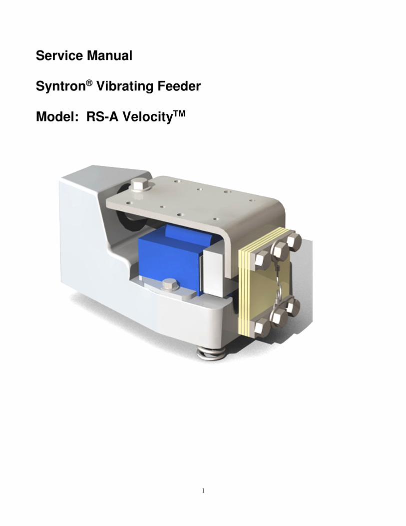
Service Instructions Syntron® Vibrating Feeder Model: RS-A VelocityTM
1
Service Manual Syntron® Vibrating Feeder Model: RS-A VelocityTM
2
Table of Contents Page GENERAL
Safety Instructions ………………………………………… 3
Introduction………………………………………………… 4
Theory of Operation……………..………………………… 4
Unpacking / Long-Term Storage………………………….. 5
Installation…………………………………………………..5
Operation……………………………………………………6
Maintenance……………………………………………….. 7
Troubleshooting……………………………………………. 8
Spring Replacement……………………………………….. 9
Adjusting the Air Gap………….………………………….. 9
Stroke Gauge………………………………………………. 10
Checking Feeder Current…………..……………………… 11
Tuning Procedure..……..………………………………….. 11
Operating Specifications…………………………………… 13
Torque Specifications……………………………………… 13
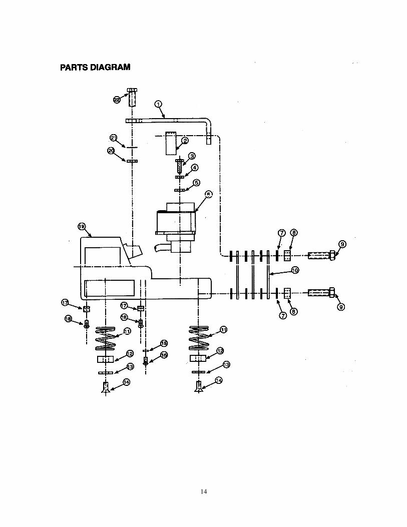
Parts Diagram……………………………………………… 14
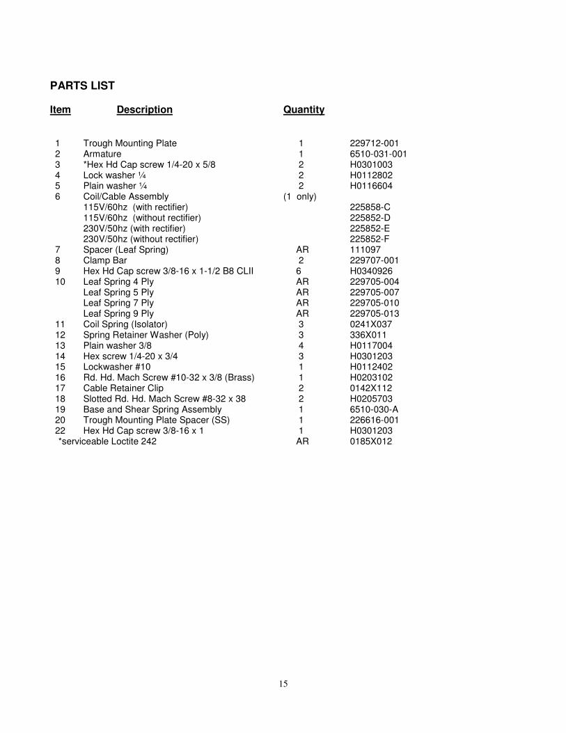
Parts List…………………………………………………… 15
3
Safety Instructions The purpose of safety symbols is to attract your attention to possible danger. Safety symbols, and their
explanations, deserve careful attention and understanding. The safety warnings do not by themselves
eliminate any danger. The instructions or warnings they give are not substitutes for proper safety
procedures.
SYMBOL MEANING
Safety Alert Symbol: Indicates DANGER, WARNING, or CAUTION. Attention is required in order to avoid serious personal injury. This
symbol may also be used in conjunction with other symbols or pictographs. NOTE: Notes advise you of information or instructions vital to the operation or
maintenance of the equipment.
IMPORTANT SAFETY INFORMATION
REAL ALL INSTRUCTIONS BEFORE OPERATING
• Upon receipt, unpack and inspect the unit for damages that may have occurred during shipment. If damage is found, contact the shipping carrier and Syntron Material Handling immediately.
• Read instructions carefully. Be familiar with the controls and proper use of the unit.
• Do not operate the unit when tired, ill, or under the influence of alcohol, drugs or medication.
Product safety labels must remain highly visible on the equipment. Establish a regular schedule to
check visibility. If you need to replace safety labels, contact Syntron Material Handling, Material
Handling Solutions Operation for an additional supply free of charge.
The instructions and data herein are vital to the proper installation and operation of this equipment. In
order to avoid delays due to faulty installation or operation, please see that these instructions are read by
the persons who will install, operate and maintain this equipment.
NOTE: Supporting information, such as drawings, may be attached to the manual. The information contained therein takes precedence over corresponding information printed in this manual.
4
INTRODUCTION The Syntron® Velocity™ Vibrating Feeder is a highly versatile vibrating feeder specifically designed to
provide accurate feeding to weigh buckets in combination weigh scales, but also ideal for other bulk
feeding applications where high stroke or fast feed rate is required. Versatility is the key that makes the
Velocity feeder capable of handling products formally considered difficult to feed.
THEORY OF OPERATION The Velocity Feeder is an electromagnetic feeder that consists of a trough and trough mounting bracket
coupled to an electromagnetic drive by means of fiberglass leaf springs and elastomeric shear springs.
The leaf springs are clamped to the base housing at the bottom, and to the trough mounting bracket at
the top by hex head cap screws. The elastomeric shear spring is bonded into the base housing unit.
The drive incorporates an electromagnet which is located within and connected to the base and shear
spring assembly. An armature assembly, also included as part of the drive unit, is located opposite the
magnet and is connected directly to the trough mounting bracket which is attached to the trough
assembly.
The Velocity Feeder produces a vibrating stroke on the surface of the feeder trough. The stroke is
created when the electromagnet pulls the trough assembly sharply down and back and then releases it to
spring up and forward. When repeated at high speeds (3600 vpm at 60 Hz), this action produces a
definite vibratory movement on the trough surface.
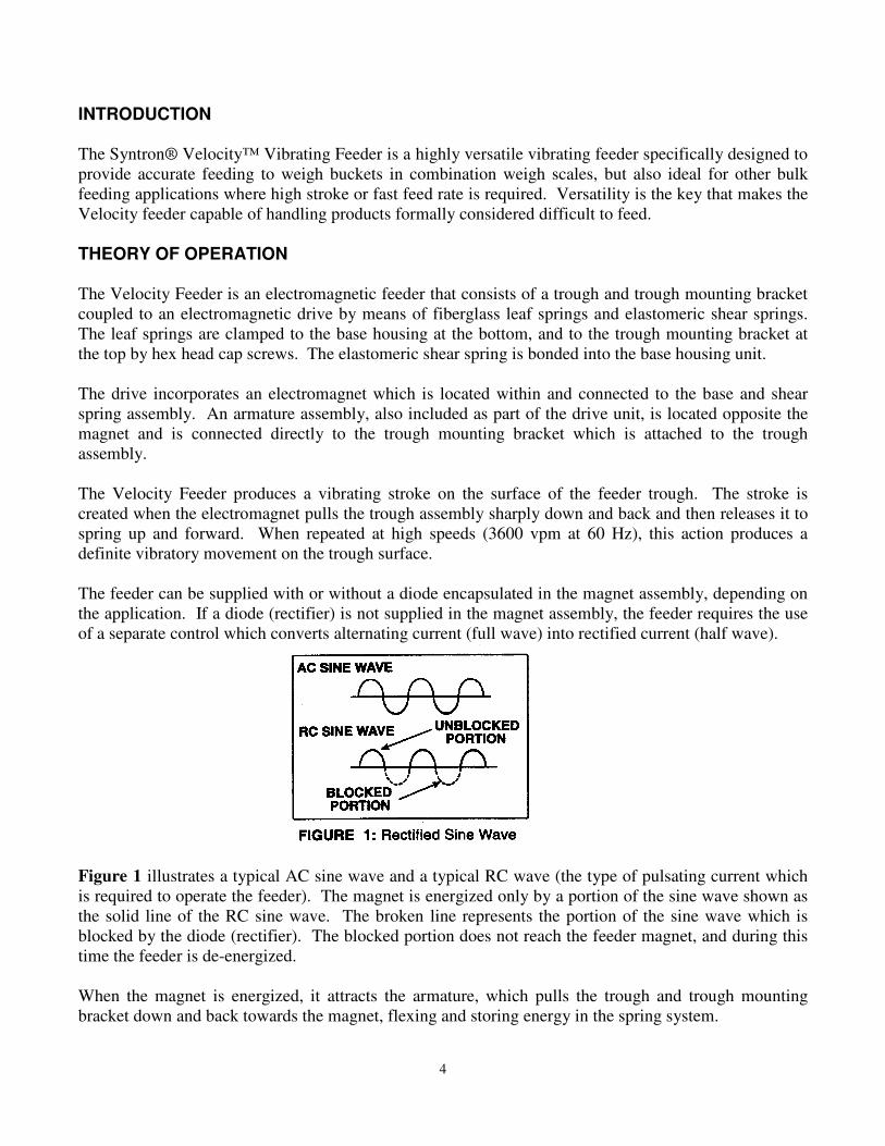
The feeder can be supplied with or without a diode encapsulated in the magnet assembly, depending on
the application. If a diode (rectifier) is not supplied in the magnet assembly, the feeder requires the use
of a separate control which converts alternating current (full wave) into rectified current (half wave).
Figure 1 illustrates a typical AC sine wave and a typical RC wave (the type of pulsating current which
is required to operate the feeder). The magnet is energized only by a portion of the sine wave shown as
the solid line of the RC sine wave. The broken line represents the portion of the sine wave which is
blocked by the diode (rectifier). The blocked portion does not reach the feeder magnet, and during this
time the feeder is de-energized.
When the magnet is energized, it attracts the armature, which pulls the trough and trough mounting
bracket down and back towards the magnet, flexing and storing energy in the spring system.
5
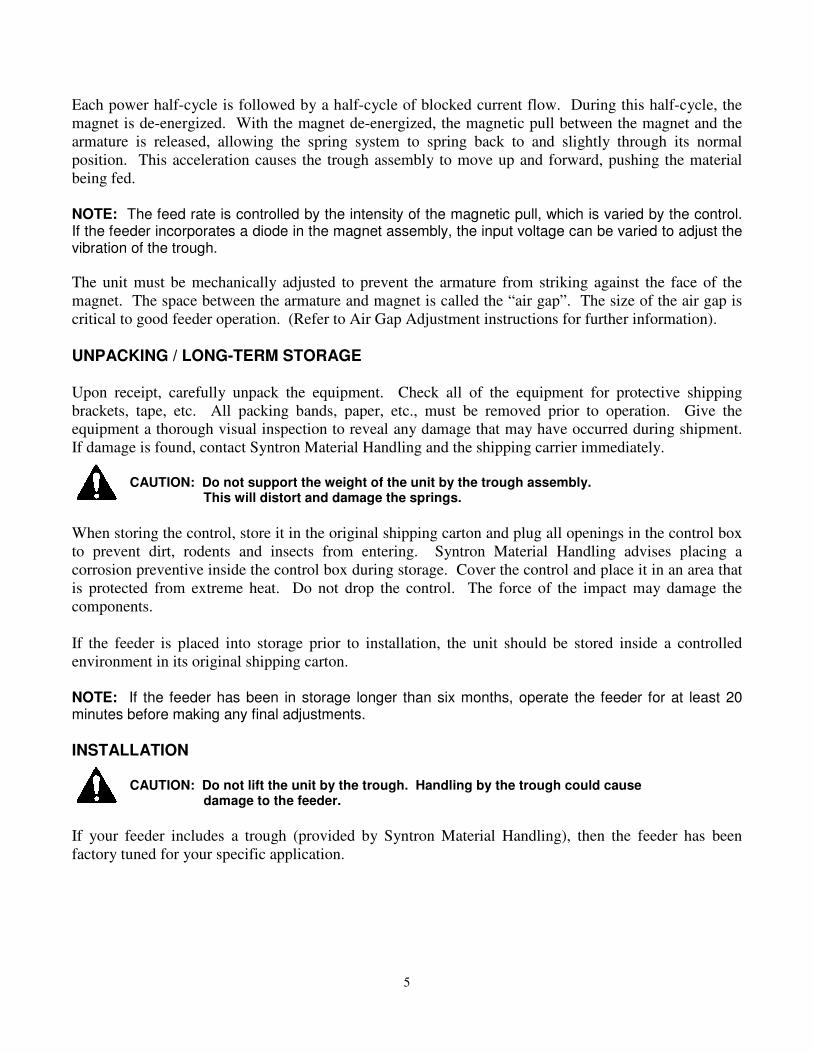
Each power half-cycle is followed by a half-cycle of blocked current flow. During this half-cycle, the
magnet is de-energized. With the magnet de-energized, the magnetic pull between the magnet and the
armature is released, allowing the spring system to spring back to and slightly through its normal
position. This acceleration causes the trough assembly to move up and forward, pushing the material
being fed.
NOTE: The feed rate is controlled by the intensity of the magnetic pull, which is varied by the control. If the feeder incorporates a diode in the magnet assembly, the input voltage can be varied to adjust the vibration of the trough.
The unit must be mechanically adjusted to prevent the armature from striking against the face of the
magnet. The space between the armature and magnet is called the “air gap”. The size of the air gap is
critical to good feeder operation. (Refer to Air Gap Adjustment instructions for further information).
UNPACKING / LONG-TERM STORAGE Upon receipt, carefully unpack the equipment. Check all of the equipment for protective shipping
brackets, tape, etc. All packing bands, paper, etc., must be removed prior to operation. Give the
equipment a thorough visual inspection to reveal any damage that may have occurred during shipment.
If damage is found, contact Syntron Material Handling and the shipping carrier immediately.
CAUTION: Do not support the weight of the unit by the trough assembly. This will distort and damage the springs.
When storing the control, store it in the original shipping carton and plug all openings in the control box
to prevent dirt, rodents and insects from entering. Syntron Material Handling advises placing a
corrosion preventive inside the control box during storage. Cover the control and place it in an area that
is protected from extreme heat. Do not drop the control. The force of the impact may damage the
components.
If the feeder is placed into storage prior to installation, the unit should be stored inside a controlled
environment in its original shipping carton.
NOTE: If the feeder has been in storage longer than six months, operate the feeder for at least 20 minutes before making any final adjustments.
INSTALLATION
CAUTION: Do not lift the unit by the trough. Handling by the trough could cause damage to the feeder.
If your feeder includes a trough (provided by Syntron Material Handling), then the feeder has been
factory tuned for your specific application.
6
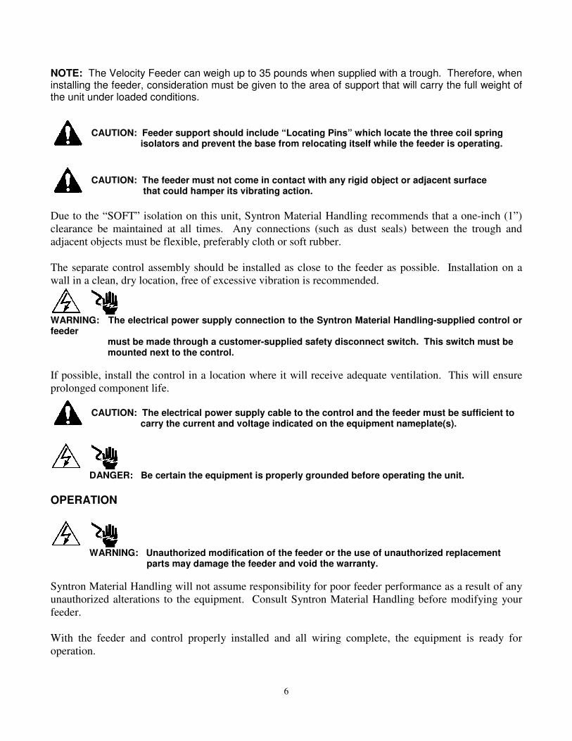
NOTE: The Velocity Feeder can weigh up to 35 pounds when supplied with a trough. Therefore, when installing the feeder, consideration must be given to the area of support that will carry the full weight of the unit under loaded conditions.
CAUTION: Feeder support should include “Locating Pins” which locate the three coil spring isolators and prevent the base from relocating itself while the feeder is operating.
CAUTION: The feeder must not come in contact with any rigid object or adjacent surface that could hamper its vibrating action.
Due to the “SOFT” isolation on this unit, Syntron Material Handling recommends that a one-inch (1”)
clearance be maintained at all times. Any connections (such as dust seals) between the trough and
adjacent objects must be flexible, preferably cloth or soft rubber.
The separate control assembly should be installed as close to the feeder as possible. Installation on a
wall in a clean, dry location, free of excessive vibration is recommended.
WARNING: The electrical power supply connection to the Syntron Material Handling-supplied control or feeder must be made through a customer-supplied safety disconnect switch. This switch must be mounted next to the control.
If possible, install the control in a location where it will receive adequate ventilation. This will ensure
prolonged component life.
CAUTION: The electrical power supply cable to the control and the feeder must be sufficient to carry the current and voltage indicated on the equipment nameplate(s).
DANGER: Be certain the equipment is properly grounded before operating the unit.
OPERATION
WARNING: Unauthorized modification of the feeder or the use of unauthorized replacement parts may damage the feeder and void the warranty.
Syntron Material Handling will not assume responsibility for poor feeder performance as a result of any
unauthorized alterations to the equipment. Consult Syntron Material Handling before modifying your
feeder.
With the feeder and control properly installed and all wiring complete, the equipment is ready for
operation.
7
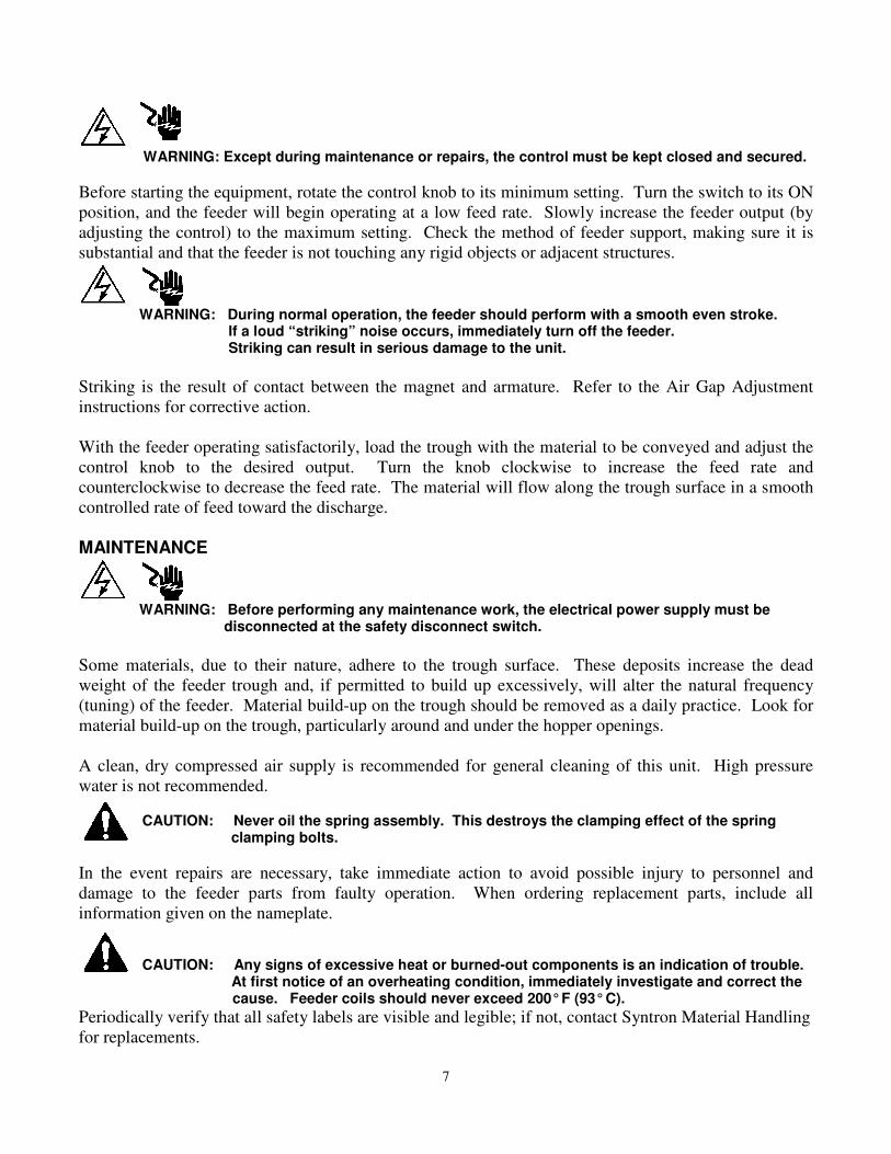
WARNING: Except during maintenance or repairs, the control must be kept closed and secured. Before starting the equipment, rotate the control knob to its minimum setting. Turn the switch to its ON
position, and the feeder will begin operating at a low feed rate. Slowly increase the feeder output (by
adjusting the control) to the maximum setting. Check the method of feeder support, making sure it is
substantial and that the feeder is not touching any rigid objects or adjacent structures.
WARNING: During normal operation, the feeder should perform with a smooth even stroke. If a loud “striking” noise occurs, immediately turn off the feeder. Striking can result in serious damage to the unit.
Striking is the result of contact between the magnet and armature. Refer to the Air Gap Adjustment
instructions for corrective action.
With the feeder operating satisfactorily, load the trough with the material to be conveyed and adjust the
control knob to the desired output. Turn the knob clockwise to increase the feed rate and
counterclockwise to decrease the feed rate. The material will flow along the trough surface in a smooth
controlled rate of feed toward the discharge.
MAINTENANCE
WARNING: Before performing any maintenance work, the electrical power supply must be disconnected at the safety disconnect switch.
Some materials, due to their nature, adhere to the trough surface. These deposits increase the dead
weight of the feeder trough and, if permitted to build up excessively, will alter the natural frequency
(tuning) of the feeder. Material build-up on the trough should be removed as a daily practice. Look for
material build-up on the trough, particularly around and under the hopper openings.
A clean, dry compressed air supply is recommended for general cleaning of this unit. High pressure
water is not recommended. CAUTION: Never oil the spring assembly. This destroys the clamping effect of the spring clamping bolts.
In the event repairs are necessary, take immediate action to avoid possible injury to personnel and
damage to the feeder parts from faulty operation. When ordering replacement parts, include all
information given on the nameplate. CAUTION: Any signs of excessive heat or burned-out components is an indication of trouble. At first notice of an overheating condition, immediately investigate and correct the
cause. Feeder coils should never exceed 200° F (93° C).
Periodically verify that all safety labels are visible and legible; if not, contact Syntron Material Handling
for replacements.
8
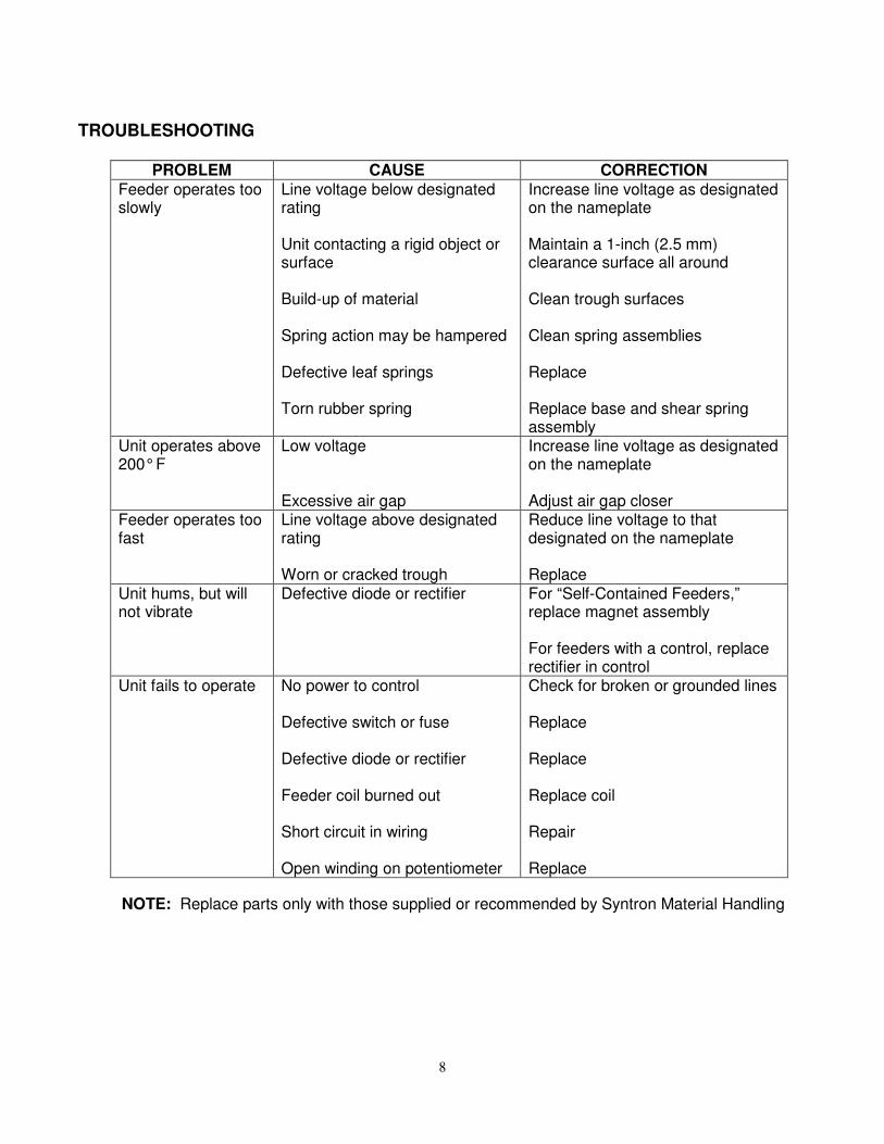
TROUBLESHOOTING
PROBLEM CAUSE CORRECTION
Feeder operates too slowly
Line voltage below designated rating Unit contacting a rigid object or surface Build-up of material Spring action may be hampered Defective leaf springs Torn rubber spring
Increase line voltage as designated on the nameplate Maintain a 1-inch (2.5 mm) clearance surface all around Clean trough surfaces Clean spring assemblies Replace Replace base and shear spring assembly
Unit operates above 200° F
Low voltage Excessive air gap
Increase line voltage as designated on the nameplate Adjust air gap closer
Feeder operates too fast
Line voltage above designated rating Worn or cracked trough
Reduce line voltage to that designated on the nameplate Replace
Unit hums, but will not vibrate
Defective diode or rectifier For “Self-Contained Feeders,” replace magnet assembly For feeders with a control, replace rectifier in control
Unit fails to operate No power to control Defective switch or fuse Defective diode or rectifier Feeder coil burned out Short circuit in wiring Open winding on potentiometer
Check for broken or grounded lines Replace Replace Replace coil Repair Replace
NOTE: Replace parts only with those supplied or recommended by Syntron Material Handling
9
LEAF SPRING REPLACEMENT Due to normal wear and tear under operating conditions, the leaf springs will eventually need to be
replaced. Replacing the leaf springs must be of the same size and thickness as the springs that were
removed. Syntron Material Handling recommends replacing all of the leaf springs at one time, rather
than just the one that failed.
WARNING: Before performing any maintenance work, the electrical power supply must be disconnected at the safety disconnect switch.
Before replacing the springs, disconnect the feeder from the power supply. Make note of the location
and arrangement of each spring, spacer and clamp. Remove the bolts that secure the leaf springs to the
base unit, then remove the remaining cap crews that secure the leaf springs to the trough mounting
bracket. Install the new springs in the reverse order, starting with the last spring removed. Replace cap
screws and torque as specified in Table 2, Torque Specifications.
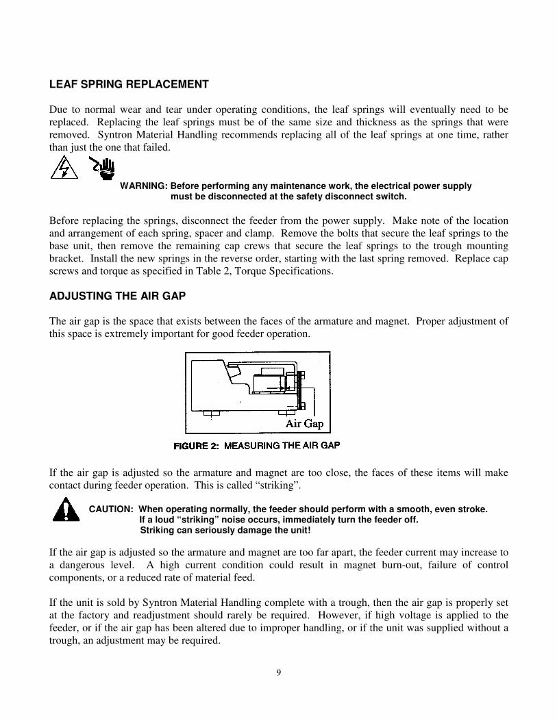
ADJUSTING THE AIR GAP
The air gap is the space that exists between the faces of the armature and magnet. Proper adjustment of
this space is extremely important for good feeder operation.
If the air gap is adjusted so the armature and magnet are too close, the faces of these items will make
contact during feeder operation. This is called “striking”.
CAUTION: When operating normally, the feeder should perform with a smooth, even stroke. If a loud “striking” noise occurs, immediately turn the feeder off.
Striking can seriously damage the unit!
If the air gap is adjusted so the armature and magnet are too far apart, the feeder current may increase to
a dangerous level. A high current condition could result in magnet burn-out, failure of control
components, or a reduced rate of material feed.
If the unit is sold by Syntron Material Handling complete with a trough, then the air gap is properly set
at the factory and readjustment should rarely be required. However, if high voltage is applied to the
feeder, or if the air gap has been altered due to improper handling, or if the unit was supplied without a
trough, an adjustment may be required.
10
The air gap adjustment is a very delicate procedure and may require some time and several attempts to
properly obtain the desired setting. The correct air gap spacing will be obtained when the armature and
magnet faces are as close as possible without “striking” when the maximum power is applied to the
feeder.
To set the air gap, loosen the two slotted round head machine screws (#18) securing the cable retainer
clips (#17), then loosen the hex head cap screws (#3) securing the magnet assembly (#6), and slide the
magnet as required. Use a set of long feeler gauges to get an even gap across the pole faces. The air gap
is typically between 0.110 inches (2.8 mm) and 0.125 inches (3.2 mm).
After each adjustment of the air gap, secure the magnet in place by tightening the hex head cap screws
(#3). After the air gap has been satisfactorily adjusted, retighten the machine screws securing the cable
retainer clips.
The Velocity feeder operates with a trough stroke of between 0.090 inches (2.3 mm) and 0.095 inches
(2.4 mm). The feeder stroke can be determined by checking the stroke gauges located on the trough
assembly. See the instructions for measuring the stroke in the stroke gauge section below.
STROKE GAUGE
The feeder stroke is the distance the trough travels in one complete cycle of vibration. This is measured
from the forward upward limit to the downward backward limit of the vibrating stroke.
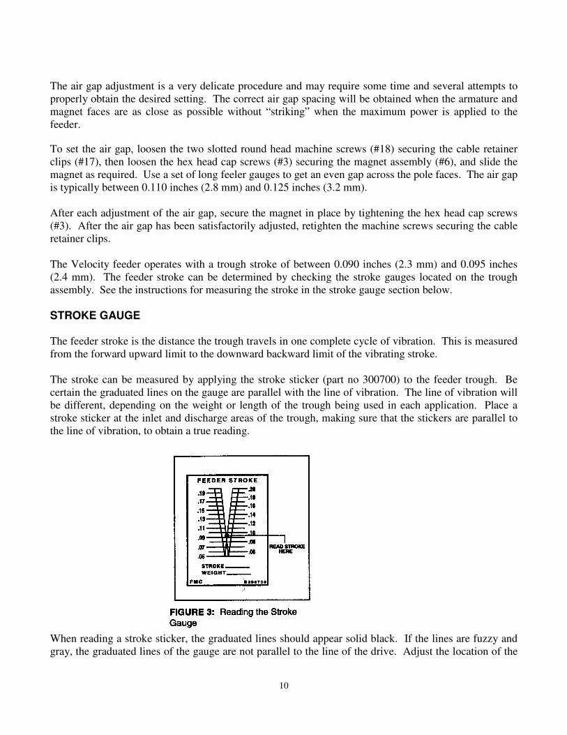
The stroke can be measured by applying the stroke sticker (part no 300700) to the feeder trough. Be
certain the graduated lines on the gauge are parallel with the line of vibration. The line of vibration will
be different, depending on the weight or length of the trough being used in each application. Place a
stroke sticker at the inlet and discharge areas of the trough, making sure that the stickers are parallel to
the line of vibration, to obtain a true reading.
When reading a stroke sticker, the graduated lines should appear solid black. If the lines are fuzzy and
gray, the graduated lines of the gauge are not parallel to the line of the drive. Adjust the location of the
11
stroke sticker parallel to the drive line. Under vibration, a black inverted “V” will appear. The feeder
stroke can be read at the apex of this black “V”.
CHECKING FEEDER CURRENT All current readings must be taken at the control. When using a true RMS meter, the current reading is
as indicated. When using a “Clamp On” meter in a circuit containing a diode (rectifier), the meter is
influenced by the modified wave form; apply a 1.7 multiplier to the meter reading to obtain the true
current draw.
TUNING PROCEDURE Step Number Step Description
1 Refer to the Air Gap Adjustment instructions for directions on setting the air gap.
Be sure to check the gap on both sides of the armature. This will ensure the armature
face is parallel to the magnet face.
2 Assemble the trough to the unit using a quantity of springs that will achieve a system
natural frequency of 59.1 Hz. The system natural frequency is most easily determined
with a variable frequency control. Always determine the system natural frequency at
the maximum stroke. If using a variable frequency control, go to step 4.
3 If using an SMH Syntron® Rectified Control such as the PowerPulseTM Control, set the
potentiometer to its maximum setting. This ensures the unit is receiving full power.
4 Check the stroke, once the feeder drive and trough unit is assembled. Refer to the Stroke
Gauge section of this manual. With the feeder trough empty, the stroke should be
checked at both the inlet and discharge ends of the trough. The inlet stroke may be
different than the discharge stroke.
5 If the stroke is not at or near 0.095 inches (2.4 mm), use a variable frequency control to
check the relationship of the operating feeder to resonance. If a variable frequency
control is not available, clamp a small [approximately 1/3 lb. (15 kg.) or less] C-clamp to
the trough. If the trough stroke gets smaller, the unit is on the correct side of resonance.
If the stroke gets larger, the unit is on the wrong side of resonance. Remove the leaf
springs one by one until the unit is on the proper side of resonance.
6 Once on the correct side of resonance, adjust the stroke. Add springs to increase stroke;
subtract springs to decrease stroke. Always begin by adding or removing the thinnest
spring possible.
NOTE: Re-torque the spring bolts after each iteration. Refer to Torque Specifications, Table 2.
7 Repeat spring adjustments until the trough stroke is between 0.090 inches (2.3 mm) and
0.095 inches (2.4 mm).

12
8 If a variable frequency control is available, check the system natural frequency. It must
be 59.7 Hz or less, as stated in step 2 above.
13
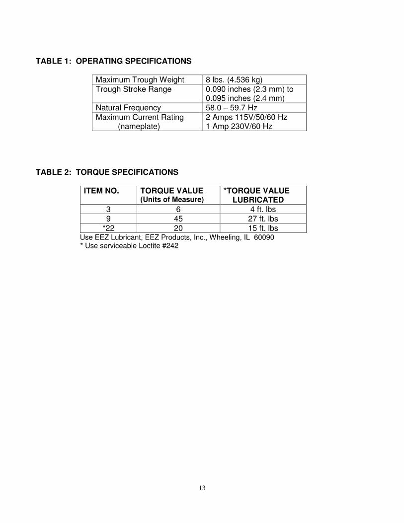
TABLE 1: OPERATING SPECIFICATIONS
Maximum Trough Weight 8 lbs. (4.536 kg) Trough Stroke Range 0.090 inches (2.3 mm) to
0.095 inches (2.4 mm) Natural Frequency 58.0 – 59.7 Hz
Maximum Current Rating (nameplate)
2 Amps 115V/50/60 Hz 1 Amp 230V/60 Hz
TABLE 2: TORQUE SPECIFICATIONS
ITEM NO. TORQUE VALUE (Units of Measure)
*TORQUE VALUE LUBRICATED
3 6 4 ft. lbs 9 45 27 ft. lbs
*22 20 15 ft. lbs Use EEZ Lubricant, EEZ Products, Inc., Wheeling, IL 60090 * Use serviceable Loctite #242
14
15
PARTS LIST Item Description Quantity 1 Trough Mounting Plate 1 229712-001 2 Armature 1 6510-031-001 3 *Hex Hd Cap screw 1/4-20 x 5/8 2 H0301003 4 Lock washer ¼ 2 H0112802 5 Plain washer ¼ 2 H0116604 6 Coil/Cable Assembly (1 only)
115V/60hz (with rectifier) 225858-C 115V/60hz (without rectifier) 225852-D 230V/50hz (with rectifier) 225852-E 230V/50hz (without rectifier) 225852-F
7 Spacer (Leaf Spring) AR 111097 8 Clamp Bar 2 229707-001 9 Hex Hd Cap screw 3/8-16 x 1-1/2 B8 CLII 6 H0340926 10 Leaf Spring 4 Ply AR 229705-004 Leaf Spring 5 Ply AR 229705-007 Leaf Spring 7 Ply AR 229705-010 Leaf Spring 9 Ply AR 229705-013 11 Coil Spring (Isolator) 3 0241X037 12 Spring Retainer Washer (Poly) 3 336X011 13 Plain washer 3/8 4 H0117004 14 Hex screw 1/4-20 x 3/4 3 H0301203 15 Lockwasher #10 1 H0112402 16 Rd. Hd. Mach Screw #10-32 x 3/8 (Brass) 1 H0203102 17 Cable Retainer Clip 2 0142X112 18 Slotted Rd. Hd. Mach Screw #8-32 x 38 2 H0205703 19 Base and Shear Spring Assembly 1 6510-030-A 20 Trough Mounting Plate Spacer (SS) 1 226616-001 22 Hex Hd Cap screw 3/8-16 x 1 1 H0301203
*serviceable Loctite 242 AR 0185X012

16
Important
Syntron Material Handling reserves the right to alter at any time, without notice and without liability or
other obligations on its part, materials, equipment specifications, and models. Syntron Material
Handling also reserves the right to discontinue the manufacture of models, parts, and components
thereof.
Your satisfaction is very important to us. Please direct any comments, questions, or concerns to
our Marketing Communications Department.

Corporate Office
P.O. Box 1370 Tupelo, Mississippi 38802
Phone: 662.869.5711 Fax: 662.869.7449
Tupelo 2730 Hwy 145 South Saltillo, Mississippi 38866 Phone: 662.869.5711 Fax: 662.869.7493 Toll Free: 800.356.4898 [email protected]
Changshu #2 Road No. 1 Changshu Export Processing Zone Changshu, Jiangsu, China 215513 Phone: +86 0512.52299002 Fax: +86 0512.52297228 [email protected]
Form No. SM0524_122214 Printed in U.S.A


![Food Hygiene.ppt [Rectified] Rev 3](https://img.pdfslide.tips/doc/110x75/552ecfdc4a7959c6598b4a0d/food-hygieneppt-rectified-rev-3.jpg)