Embed Size (px)
Citation preview
Page 1HBX Control Systems Inc.
ECO-1000
Central Processing Unit 1000Version 1.33
Solar Programming Guide
H B X E C O - 1 0 0 0 H V A C C o n t r o lV e r s i o n 1 . 3 3
Page 2
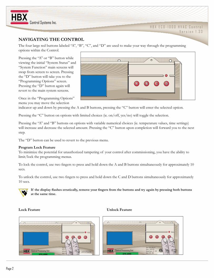
NAVIGATING THE CONTROLThe four large red buttons labeled “A”, “B”, “C”, and “D” are used to make your way through the programming options within the Control.
Pressing the “A” or “B” button while viewing the initial “System Status” and “System Function” main screens will swap from screen to screen. Pressing the “D” button will take you to the “Programming Options” screen. Pressing the “D” button again will revert to the main system screens.
Once in the “Programming Options” menu you may move the selection indicator up and down by pressing the A and B buttons, pressing the “C” button will enter the selected option.
Pressing the “C” button on options with limited choices (ie. on/off, yes/no) will toggle the selection.
Pressing the “A” and “B” buttons on options with variable numerical choices (ie. temperature values, time settings) will increase and decrease the selected amount. Pressing the “C” button upon completion will forward you to the next step.
The “D” button can be used to revert to the previous menu.
AA BB CC DD
I 120VAC 60H 5A
Program Lock FeatureTo minimize the potential for unauthorized tampering of your control after commissioning, you have the ability to limit/lock the programming menus.
����������������� ���������������������������������������������������������������������������������������secs.
������������������� �������������������������������������!�����"����������������������������������������������#
�� �������� ��� ������ �� ��������������������������������������� ������� � �����������������������at the same time.
������� ����� � � � � � ��������� ����
AA BB CC DD
Input: 120VAC 60Hz 5A
Relays: 240VAC 10A
Demand Signal: 20 - 240V
Model: CPU - 1000
Certified to CSA C22.2 No 24Conforms to UL Standard 873
AA BB CC DD
Input: 120VAC 60Hz 5A
Relays: 240VAC 10A
Demand Signal: 20 - 240V
Model: CPU - 1000
Certified to CSA C22.2 No 24Conforms to UL Standard 873
H B X E C O - 1 0 0 0 H V A C C o n t r o lV e r s i o n 1 . 3 3
© HBX Control Systems Inc. 2012 Page 3
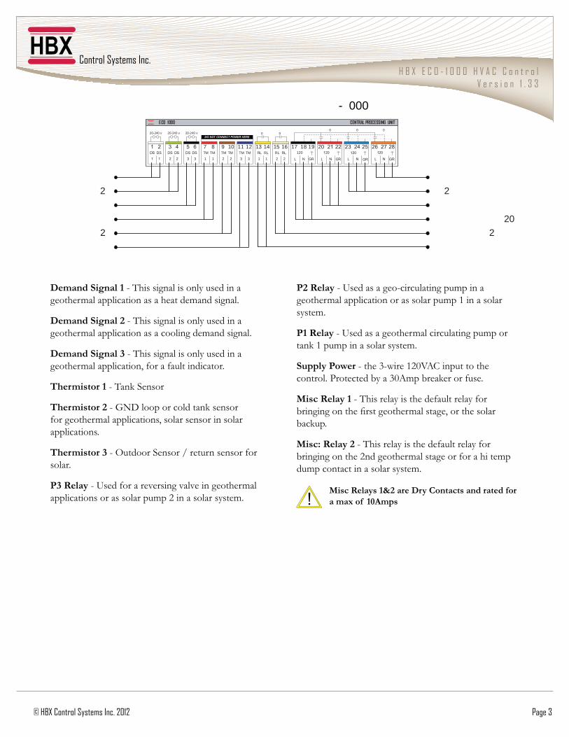
��� ���!�� ��" - This signal is only used in a geothermal application as a heat demand signal.
��� ���!�� ��# - This signal is only used in a geothermal application as a cooling demand signal.
��� ���!�� ��$�- This signal is only used in a geothermal application, for a fault indicator.
%��������"�- Tank Sensor
%��������# - GND loop or cold tank sensor for geothermal applications, solar sensor in solar applications.
%��������$ - Outdoor Sensor / return sensor for solar.
&$�'�� � - Used for a reversing valve in geothermal applications or as solar pump 2 in a solar system.
&#�'�� � - Used as a geo-circulating pump in a ��������������������������������������������������system.
&"�'�� � - Used as a geothermal circulating pump or ����������������������������#
!������&�(���$���%$�����&�'�!�������������������#�*������������%�����������������#
)��'�� ��" - This relay is the default relay for ������������������������������� ������������backup.
)�*�'�� ��# - This relay is the default relay for bringing on the 2nd geothermal stage or for a hi temp dump contact in a solar system.
)��'�� ��"+#� �������,��� ��� ���� �������� �� -��� �"/0��
21SD
1
SD
1
43SD
2
SD
2
65SD
3
SD
3 RG
02182
NL
7262
RG
02152
NL
4232
RG
02122
NL
1202
RG021
91
NL
8171LR
2LR6151
2LR
1LR4131
1MT
3MT2111
3MT
2MT019
2MT
1MT87
1
v 042-02 v 042-02 v 042-02EREH REWOP TCENNOC TON OD
0 0 0 0 0
0001 OCE TINU GNISSECORP LARTNEC
2
02 2
2 2
- 000
Control Systems Inc.
ComfortControlInnovation
H B X E C O - 1 0 0 0 H V A C C o n t r o lV e r s i o n 1 . 3 3
Page 4
Prog
ramm
ing
PROGRAMMING
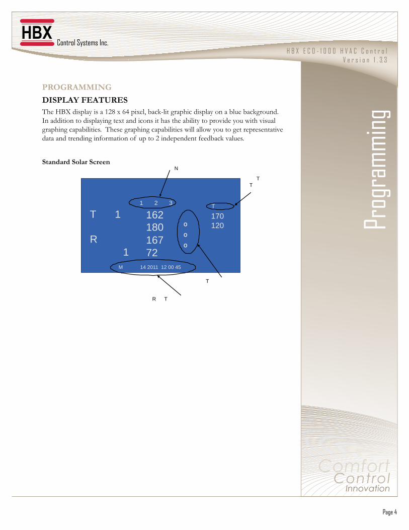
��!&�01��20%�'2!��+�0���������������&1���34����� �����$��������������������������������������#��In addition to displaying text and icons it has the ability to provide you with visual graphing capabilities. These graphing capabilities will allow you to get representative data and trending information of up to 2 independent feedback values.
!� �� ���!�� ��!�����
T 1
R1
16218016772
T
ººº
170120
1 2 3
M 14 2011 12 00 45
TT
R T
T
N
Page 5
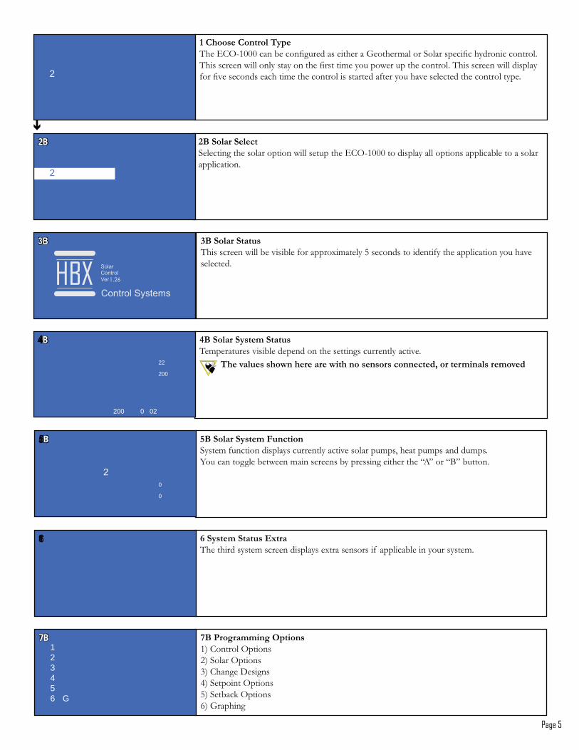
#3�!�� ��!�����5����������������������������������6!7$�������������������������������������������������application.
2B2B
2
$3�!�� ��!� ��This screen will be visible for approximately 5 seconds to identify the application you have selected.
1.26
43�!�� ��!�����!� ��Temperatures visible depend on the settings currently active.
%���� ������(������� ���(������������������������������ ���������
BB
22
200
200 0 02
"�,�����,�������%�����6!7$�����������������������������9����������5���������������������������#������������������������������������������������������������#����������������������������:���������������������������������������������:��������������������#
2
53�!�� ��!������������System function displays currently active solar pumps, heat pumps and dumps.You can toggle between main screens by pressing either the “A” or “B” button.
BB
2 0
0
63�&���� �����7�����;�!�������7������2) Solar Options3) Change Designs4;�5�������7������5) Setback Options3;�9������
7B7B123456 G
8�!�����!� ���2-�� The third system screen displays extra sensors if applicable in your system.
Page 6
93�,�������7����The control options area contains options for changing the display, setting constant heat/cooling demands; testing/viewing activity and enabling zone control. To enter the desired ������� ��������>!?�������#�@�������� �����������E����� �������������>!?��������the “Control Options screen”.
BB
2
4
"#�,� ����%��*�1� �Select the appropriate year by pressing the “A” button to decrease and the “B” button to increase the year. Press the “C” button to proceed.
22 2000
:3���� ��7����*�)���Display options allow you to: set your date and time; reset the internal relay counter for pump and heat pump cycles; program and display either ºF or ºC; program the Control to allow for Daylight Savings; access website information for HBX; and clear the stage accumulated hours counter.
BB
2 2
4
"/���� ��7����*�)���Display options allow you to: set your date and time; reset the internal relay counter for pump and heat pump cycles; program and display either ºF or ºC; program the Control to allow for Daylight Savings; access website information for HBX; and clear the stage accumulated hours counter.
2
4 - v
""���� ��7����*�,� ����%��K������������������������������������������������!���������������������������options, as the real-time settings are effected by the “Change Time” feature.
11111 T2 R34 N56 R R T
"$�,� ����%��*�)����5����������������������L�$�&;��������������>�?�����������������������>�?�button to increase the month. Press the “C” button to proceed.
00
"4�,� ����%��*�� �5����������������������� ��������L�$%�;��������������>�?���������������������the “B” button to increase the day. Press the “C” button to proceed.
00
Page 7
"9���� ��7����*�'����,����Pressing the “C” button with the “Reset Cycles” option selected will reset the internal relay counter for heat pumps and heat pump cycles. Heat pump and pump cycles are visible on the “System Function” screen.
2
4 - v
":���� ��7����*���� ����;�<;,Pressing the “C” button with the “Display in °F/°C” option selected will allow you to program the Control and display in either ºF or ºC scales.
2
4 - v
#/���� ��7����*��=����! ���Pressing the “C” button with the “D-Lite Savings” option selected will allow you to program the Control to allow for Daylight Savings time shifting.
22
2
4 - v
#"���� ��7����*�,��� ���>3?Pressing the “C” button with the “Contact HBX” option selected will display the manufacturer contact information and the units individual serial number.
22
2
4 - v
"5�,� ����%��*�@���� �5����������������������� ������L�$Q;��������������>�?�����������������������“B” button to increase the day. Press the “C” button to proceed.
!��� ��B�"
1111
"8�,� ����%��*�>���5����������������������� �������L�$&4;��������������>�?�����������������������“B” button to increase the hour. Press the “C” button to proceed.
)������B�/*//
00
"6�,� ����%��*�)����5������������������������� �������L�$3�;��������������>�?���������������������the “B” button to increase the minute. Press the “C” button to proceed.
00
Page 8
##���� ��7����*�,��� ���>3?�,�������Contact HBX Controls directly and display your Controls serial number
2222
-40 - 20-002
#$���� ��7����*�'����'���%��Pressing the “C” button with the “Reset Run Times” option selected will clear the stage accumulated hours counter. To view the stage runtime, select the “Stage Run Times” option within the “Control Options” menu.
22
2
4 - v
#43�,�������7����*�0�( ��>� ����� ��Not applicable for solar applications.
2 B2 B
2 2
4
#53�,�������7��D*�0�( ��,��������� ��Not applicable for solar applications.
2 B2 B
2 2
4
#6�)�� ���) -*�%�������Allows you to look at a maximum of six different thermistor min/max temperature extremes and reset back to zero. To see updated Min/Max values return to the System Status screen to refresh the view.
1 T 12 T 23 T 34 T 45 T 56 T 67 R
M M
#9�%�������*�, �������� � Each thermistor has its highest and lowest temperatures stored, as well as the time that this temperature was reached and the period of time that it spent at this value.
220 0 0 00 �����
0 0 0 00 �����
#:�)�� ���) -*�'����0��When formatting the Control existing min/max values are reset. Selecting the “Reset All” option clears the time and date stamps.
22
2 2
4 4
Page 9
$/3�,�������7����*�%����������������������������������[����������������������%��������#
1���� ��������������� ��� �����������������J,K�������������������$/��������� ������D
2
2 4
#83�,�������7����*�)�� ���) -This allows you to view extreme temperatures that the thermistor has been subjected to. These values can be reset at any time.
2 B2 B
2 2
4
$"�%����*�'�� ��������:����������������������������#�\��������������������������������the corresponding Expansion Module connected. By continually pressing the “A” ���������������������������������������\�����]1��������#
2 2
4 4
$#�%����*�&@)The third screen is displayed by pressing the “A” button on the last selection of the previous screen. PWM relays are accessible here.
22 2
20 2 422
$$�%����*�'�� ��7��This screen informs you that the Control is reverting the relays to an off state.
$53�,�������7����*�!� ���'���%��This allows you to view cumulative run times for your heat pump stages. This is reset in the “Display Options” menu.
BB
2 2
4
$4�%����*�'�� ��7�Pressing the “C” button on selected relays will activate the test sequence.
Page 10
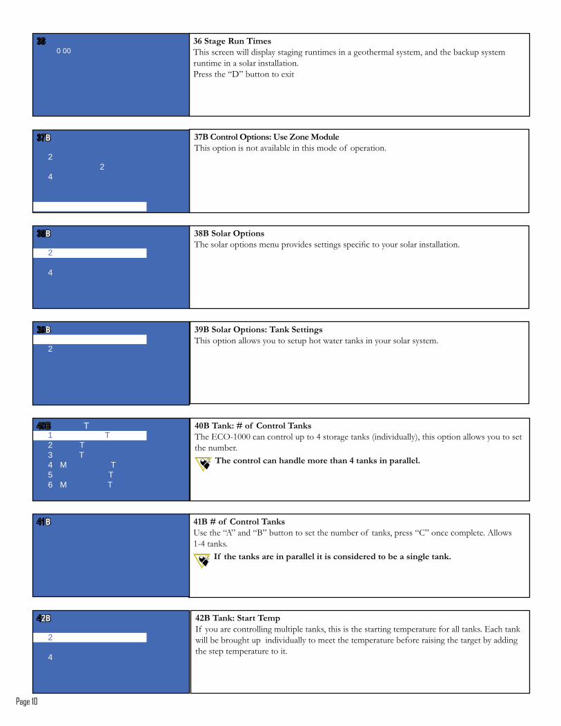
$8�!� ���'���%��This screen will display staging runtimes in a geothermal system, and the backup system runtime in a solar installation.Press the “D” button to exit
0 00
$63�,�������7����*����Q����)�����This option is not available in this mode of operation.
BB
2 2
4
$93�!�� ��7���������������������������:���������������������������������������������#
2
4
BB
$:3�!�� ��7����*�% ���!�����This option allows you to setup hot water tanks in your solar system.
2
BB
4/3�% ��*�S��� �,�������% ����6!7$�����������������������4��������������L����:�������; �����������������������������the number.
%������������ ��� ������������ ��4�� ������ � ����D
1 T2 T3 T4 M T5 T6 M T
T
4"3�S��� �,�������% ��Use the “A” and “B” button to set the number of tanks, press “C” once complete. Allows �$4������#
�� ������ ��� ������ � ����������������������� ������� ��D
BB
4#3�% ��*�!� ���%���If you are controlling multiple tanks, this is the starting temperature for all tanks. Each tank will be brought up individually to meet the temperature before raising the target by adding the step temperature to it.
2
4
2B2B
Page 11
4$3�!� ���%���Set this temperature to be the initial heat value for the tanks.K� �������������������������������� �������������������������������������������#
BB0
443�% ��*�!����%���Step temperature is used in multiple tank applications. Once each tank has reached the target tank temperature the step temperature is added to the target to increase the target for each tank.
2
4
BB
453�!����%���Choose the desired value for each step to raise the target temperature in multiple tank applications. The step temperature will be added to the target when all tanks have reached the target temperature.
BB0
483�% ��*�)��3 �����%���This setting is used if there is a backup present in the system.
2
4
BB
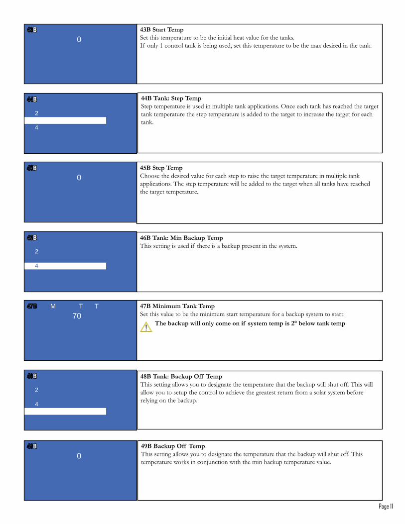
463�)�����% ���%���Set this value to be the minimum start temperature for a backup system to start.
%���� �����(����������������� ������������#;�����(�� �������
M T T70
493�% ��*�3 �����7�� �%���This setting allows you to designate the temperature that the backup will shut off. This will allow you to setup the control to achieve the greatest return from a solar system before relying on the backup.
2
4
BB
4:3�3 �����7�� �%���This setting allows you to designate the temperature that the backup will shut off. This temperature works in conjunction with the min backup temperature value.
BB0
Page 12
5/3�% ��*�) -������%���This value is set to the maximum temperature that you desire within the tank.
2
4
BB
5"3�) -����% ���%���This is the maximum temperature that you desire within the tank. After this temperature is achieved the dump contact will close, allowing heat to be taken out of the system before overheating occurs.
BB0
5#3�!�� �*�!�� ��!������������������������������������������������#
2
2B2B
5$3�!�� �*�)��!�� �This value is set to the minimum solar temperature at the start of a solar cycle.
2 2
4
BB
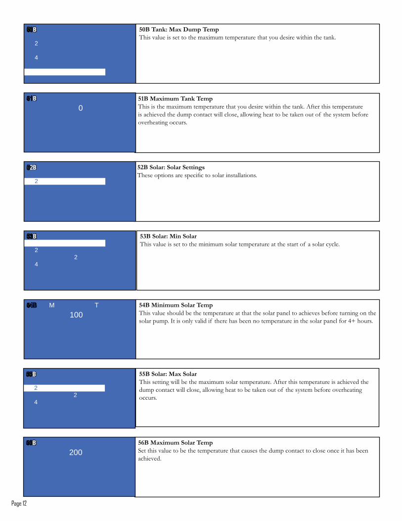
543�)�����!�� ��%���This value should be the temperature at that the solar panel to achieves before turning on the ����������#�K����������:������� ������������������������������������������4^�����#
M T100
553�!�� �*�) -�!�� �This setting will be the maximum solar temperature. After this temperature is achieved the dump contact will close, allowing heat to be taken out of the system before overheating occurs.
2
2 4
BB
583�) -����!�� ��%���Set this value to be the temperature that causes the dump contact to close once it has been achieved.
BB 200
Page 13
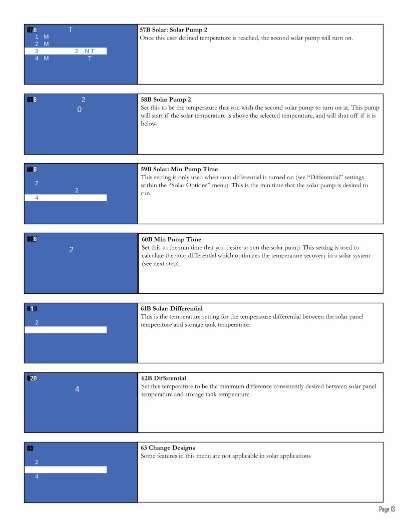
563�!�� �*�!�� ��&����#7�������������������������������� ��������������������������������#1 M
2 M3 2 N T4 M T
TBB
593�!�� ��&����#Set this to be the temperature that you wish the second solar pump to turn on at. This pump will start if the solar temperature is above the selected temperature, and will shut off if it is below.
BB 2 0
5:3�!�� �*�)��&����%��This setting is only used when auto differential is turned on (see “Differential” settings within the “Solar Options” menu). This is the min time that the solar pump is desired to run.
2
2 4
BB
8/3�)��&����%��Set this to the min time that you desire to run the solar pump. This setting is used to calculate the auto differential which optimizes the temperature recovery in a solar system (see next step).
BB
2
8"3�!�� �*��������� �This is the temperature setting for the temperature differential between the solar panel temperature and storage tank temperature.
2
11
8#3��������� �Set this temperature to be the minimum difference consistently desired between solar panel temperature and storage tank temperature.
2B2B 4
8$�,� ��������Some features in this menu are not applicable in solar applications
2
4
Page 14
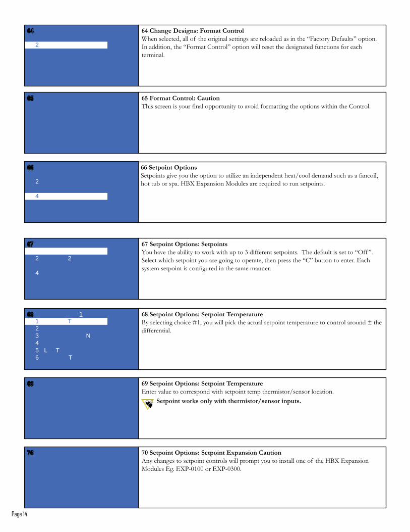
86�!�������7����*�!������You have the ability to work with up to 3 different setpoints. The default is set to “Off ”.Select which setpoint you are going to operate, then press the “C” button to enter. Each ����������������������������������������#
2 2
4
88�!�������7����Setpoints give you the option to utilize an independent heat/cool demand such as a fancoil, hot tub or spa. HBX Expansion Modules are required to run setpoints.
2
4
84�,� ��������*����� ��,������When selected, all of the original settings are reloaded as in the “Factory Defaults” option. In addition, the “Format Control” option will reset the designated functions for each terminal.
2
85����� ��,������*�, ������������������������������������������:���������������������������������!������#
89�!�������7����*�!�������%����� ��������������������]� �����������������������������������������������������������_���differential.
1 T23 N45 L T6 T
1
8:�!�������7����*�!�������%����� ����Enter value to correspond with setpoint temp thermistor/sensor location.
!�������(���������(�����������<���������D
6/�!�������7����*�!�������2-� ����, ����Any changes to setpoint controls will prompt you to install one of the HBX Expansion `������6�#�60*$��������60*$�%��#
Page 15
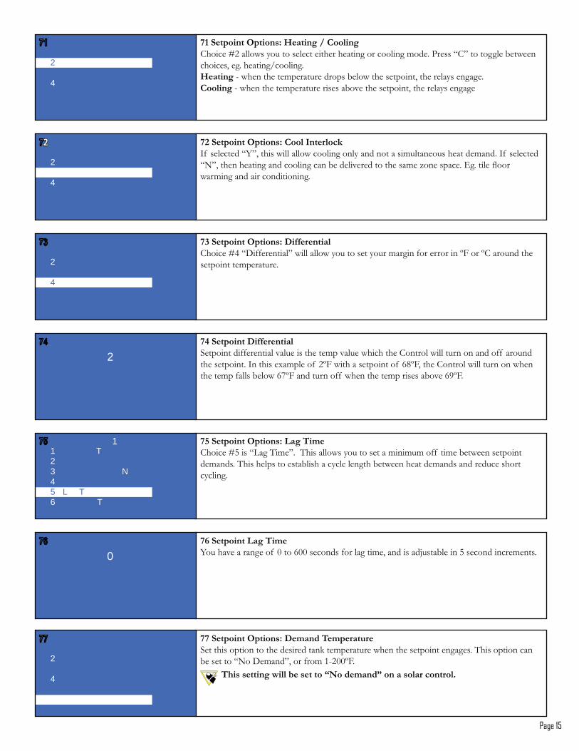
6"�!�������7����*�>� ����<�,�����Choice #2 allows you to select either heating or cooling mode. Press “C” to toggle between choices, eg. heating/cooling.>� ��� - when the temperature drops below the setpoint, the relays engage.,����� - when the temperature rises above the setpoint, the relays engage
2
4
6#�!�������7����*�,�������������If selected “Y”, this will allow cooling only and not a simultaneous heat demand. If selected >|? �������������������������������:������������}�������#�6�#�����E����warming and air conditioning.
22
2
4
6$�!�������7����*��������� �!����]4�>"���������?����������������������������������������������~@����~!����������setpoint temperature.
2
4
64�!��������������� �Setpoint differential value is the temp value which the Control will turn on and off around ���������#�K�������������� �&~@����������������� �31~@ ���!����������������������������������������3Q~@������������� ������������������:�3�~@#
2
65�!�������7����*�� ��%��Choice #5 is “Lag Time”. This allows you to set a minimum off time between setpoint demands. This helps to establish a cycle length between heat demands and reduce short cycling.
1 T23 N45 L T6 T
1
68�!�������� ��%�������:���������� ������3��������������������� �������������������������������������#
0
66�!�������7����*���� ���%����� ����Set this option to the desired tank temperature when the setpoint engages. This option can ��������>|��"����? ����������$&��~@#
%��������(������������JU����� ��K���� ��� ���������D
2
4
Page 16
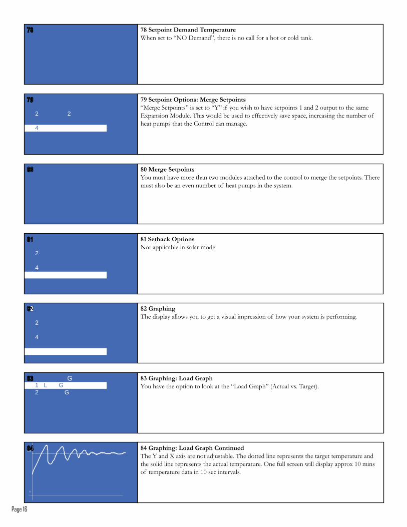
6:�!�������7����*�)�����!������>`���5�������?����������>�?��� �������������:����������������&�����������������Expansion Module. This would be used to effectively save space, increasing the number of heat pumps that the Control can manage.
2 2
4
9/�)�����!������You must have more than two modules attached to the control to merge the setpoints. There must also be an even number of heat pumps in the system.
9"�!��� ���7����Not applicable in solar mode
2
4
69�!���������� ���%����� ����When set to “NO Demand”, there is no call for a hot or cold tank.
9$�W� ����*��� ��W� ��You have the option to look at the “Load Graph” (Actual vs. Target).1 L G
2 G
G
9#�W� ����The display allows you to get a visual impression of how your system is performing.
22
2
4
94�W� ����*��� ��W� ���,�������The Y and X axis are not adjustable. The dotted line represents the target temperature and �������������������������������������#�7������������������������������������������ ����������������������������:���#
0
200
H B X E C O - 1 0 0 0 H V A C C o n t r o lV e r s i o n 1 . 3 3
© HBX Control Systems Inc. 2012 Page 17
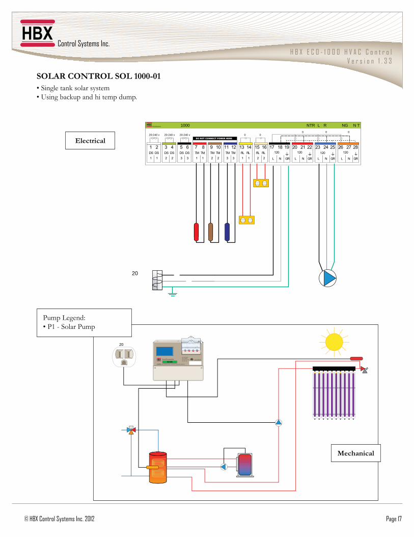
!7�0'�,7U%'7��!7��"///=/"��5��������������������� �����������������������������#
NTR L R NG N T1000
1 2DS1DS1
3 4DS2DS2
5 6DS3DS3 GR
12028
NL
2726
GR
12025
NL
2423
GRGR
12022
NL
2120120
19
NL
1817RL2RL1615
2RL1RL1413
1TM3TM1211
3TM2TM109
2TM1TM87
1
20-240 v 20-240 v 20-240 vDO NOT CONNECT POWER HERE
0 0 0 0 0
20
20BB CC DD
Input: 120VAC 60Hz 5A
Relays: 240VAC 10A
Demand Signal: 20 - 240V
Model: CPU - 1000
CAUTION, RISK OF ELECTRICAL SHOCK - DISCONNECT POWER PRIOR TO SERVICING
Certified to CSA C22.2 No 24Conforms to UL Standard 873
Central Processing Unit
ECO-1000
Electrical
)��� �� �
Pump Legend: ��*��$�5�����*���
H B X E C O - 1 0 0 0 H V A C C o n t r o lV e r s i o n 1 . 3 3
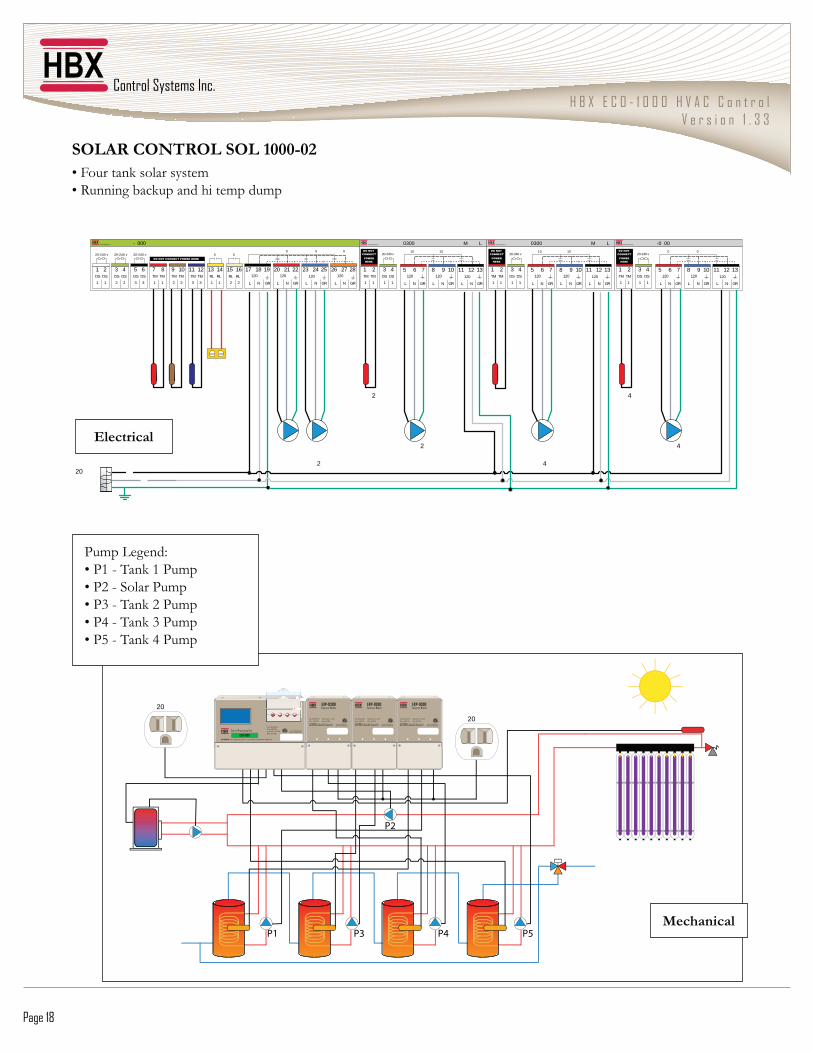
Page 18
!7�0'�,7U%'7��!7��"///=/#��@�������������������� ��\����������������������������
0300
3 4DS
1
DS
1
20-240 vDO NOT
CONNECTPOWER HERE
TM
1
TM
21
1
M L
GR
120
13
NL
1211
GR
120
10
NGRN L
98120
7
L
65
10 10
0300
3 4DS
1
DS
1
20-240 vDO NOT
CONNECTPOWER HERE
TM
1
TM
21
1
M L
GR
120
13
NL
1211
GR
120
10
NGRN L
98120
7
L
65
10 10
-0 00
3 4DS
1
DS
1
20-240 vDO NOT
CONNECTPOWER HERE
TM
1
TM
21
1
GR
120
13
NL
1211
GR
120
10
NGRN L
98120
7
L
65
0 0
- 000
1 2DS
1
DS
1
3 4DS
2
DS
2
5 6DS
3
DS
3 GR
120
28
NL
2726
GR
120
25
NL
2423
GRGR
120
22
NL
2120120
19
NL
1817RL
2
RL
1615
2
RL
1
RL
1413
1
TM
3
TM
1211
3
TM
2
TM
109
2
TM
1
TM
87
1
20-240 v 20-240 v 20-240 v DO NOT CONNECT POWER HERE
0 00 0 0
2 4
2 420
2 4
20 20
Certified to CSA C22.2 No 24 Conforms to UL Standard 873
Input: 120VAC 60Hz 2A
Relays: 240VAC 10A
Demand Signal: 20 - 240V
Model: EXP-0300
CAUTION, RISK OF ELECTRICAL SHOCK - DISCONNECT POWER PRIOR TO SERVICING
EXP-0300 Expansion Module
Certified to CSA C22.2 No 24 Conforms to UL Standard 873
Input: 120VAC 60Hz 2A
Relays: 240VAC 10A
Demand Signal: 20 - 240V
Model: EXP-0300
CAUTION, RISK OF ELECTRICAL SHOCK - DISCONNECT POWER PRIOR TO SERVICING
EXP-0300 Expansion Module
Certified to CSA C22.2 No 24 Conforms to UL Standard 873
Input: 120VAC 60Hz 2A
Relays: 240VAC 10A
Demand Signal: 20 - 240V
Model: EXP-0300
CAUTION, RISK OF ELECTRICAL SHOCK - DISCONNECT POWER PRIOR TO SERVICING
EXP-0300 Expansion Module
AA BB CC DD
Input: 120VAC 60Hz 5A
Relays: 240VAC 10A
Demand Signal: 20 - 240V
Model: CPU - 1000
CAUTION, RISK OF ELECTRICAL SHOCK - DISCONNECT POWER PRIOR TO SERVICING
Certified to CSA C22.2 No 24 Conforms to UL Standard 873
AAAAAAAAAAAAAAAAAAAAAAAAAAAAAAAAAAAAAAAAAAAAAAAAAAAAAAAAAAAAAAAAAAAAAAAAAAAAAAAAAAAAAAAAAAAAAAAAAAAAAAAAA BBBBB DDDDDDDDDDDDD
Centr a l Proces s i n g U n i t
ECO-1000
P1
P2
P3 P4 P5
Pump Legend: ��*��$��������*��� ��*&�$�5�����*��� ��*%�$������&�*��� ��*4�$������%�*��� ��*��$������4�*���
Electrical
)��� �� �
H B X E C O - 1 0 0 0 H V A C C o n t r o lV e r s i o n 1 . 3 3
© HBX Control Systems Inc. 2012 Page 19
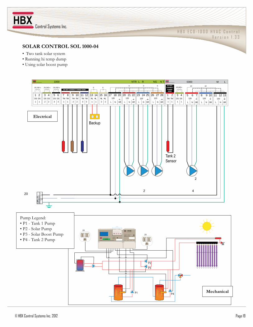
!7�0'�,7U%'7��!7��"///=/4�� �������������������� ��\����������������� ������������������������
0300
3 4DS
1
DS
1
20-240 vDO NOT
CONNECTPOWER HERE
TM
1
TM
21
1
M L
GR
120
13
NL
1211
GR
120
10
NGRN L
98120
7
L
65
10 10
NTR L R NG N T1000
1 2DS
1
DS
1
3 4DS
2
DS
2
5 6DS
3
DS
3 GR
120
28
NL
2726
GR
120
25
NL
2423
GRGR
120
22
NL
2120120
19
NL
1817RL
2
RL
1615
2
RL
1
RL
1413
1
TM
3
TM
1211
3
TM
2
TM
109
2
TM
1
TM
87
1
20-240 v 20-240 v 20-240 v DO NOT CONNECT POWER HERE
0 00 0 0
2
42
Backup
20
Tank 2 Sensor
20
20 Certified to CSA C22.2 No 24
Conforms to UL Standard 873
Input: 120VAC 60Hz 2A
Relays: 240VAC 10A
Demand Signal: 20 - 240V
Model: EXP-0300
CAUTION, RISK OF ELECTRICAL SHOCK - DISCONNECT POWER PRIOR TO SERVICING
EXP-0300 Expansion Module
AA BB CC DD
Input: 120VAC 60Hz 5A
Relays: 240VAC 10A
Demand Signal: 20 - 240V
Model: CPU - 1000
CAUTION, RISK OF ELECTRICAL SHOCK - DISCONNECT POWER PRIOR TO SERVICING
Certified to CSA C22.2 No 24 Conforms to UL Standard 873
AAAAAAAAAAAAAAAAAAAAAAAAAAAAAAAAAAAAAAAAAAAAAAAAAAAAAAAAAAAAAAAAAAAAAAAAAAAAAAAAAAAAAAAAAAAAAAAAAAAAAAAAAAAAAAAAAAA BBBBB DDDDDDDDDDD
Centr a l Proces s i n g U n i t
ECO-1000
P1
P2
P3
P4
Electrical
)��� �� �
Pump Legend: ��*��$��������*��� ��*&�$�5�����*��� ��*%�$�5�����������*��� ��*4�$������&�*���
Page 20 HBX Control Systems Inc. 2012
Phone: +1 (403) 720-0029 Fax: +1 (403) 720-0054 Email: inf o @ hbxcontrols.com Web: www.hbxcontrols.com
HBX Control Systems Inc.4516 - 112th Avenue SECalgary, AB Canada T2C 2K2
:%#4