Embed Size (px)
Citation preview
3/2 way N.C. or N.O.Ports M5 (for single base)Cartridge ø 3 and 4 (for manifold)
Directly operated mini-solenoid valves Series P
Valve group 3/2 Way / Pos., N.C. or N.O.
Construction poppet type
Mounting by means of screws
Materials plastic body - NBR seals - other stainless steel
Ports M5 - ø 3 cartridge ø 4 cartridge G1/8 manifold supply
Installation in any position
Temperature 0 ÷ 60°C
Fluid filtered air, with or without lubrication
Lubricant without lubrication**
GENERAL DATA
The Series "P" directly operated solenoid valves can work both with dry or lubricatedair. They are available as 3/2 ways, either normally closed (NC) or normally opened(NO). The main feature of this solenoidvalve consists in the fact that the body is integral with the encapsulated coil.This solution allows to have a very goodpower consumption/flow rate and guarantees high performance even with utilizations at the limits of the given values.Single or multiple manifolds are availablefor assembly in batteries.On these manifolds, it is possible toassemble both NC and NO functions (for thelatter it is necessary to use an adaptor).The manifolds are available on stockonly with cartridge fittings outlets withSUPER-RAPID Mod. 6700 for tubes of outerdia. 3 and 4 mm.
Note: All the serie P electrovalves are basicin DC. For their AC operation,at the same targe voltage you must use the 125-900 connector.
T h e c o m p a n y r e s e r v e s t h e r i g h t t o v a r y m o d e l s a n d d i m e n s i o n s w i t h o u t n o t i c e .T h e s e p r o d u c t s a r e d e s i g n e d f o r i n d u s t r i a l a p p l i c a t i o n s a n d a r e n o t s u i t a b l e f o r s a l e t o t h e g e n e r a l p u b l i c .
2.03001
S E R I E S PC a t a l o g u e 2 0 0 1
2
** In case lubricated air is used we recommend to use ISO VG32 oil.
SO
LE
NO
ID V
ALV
ES
AN
D P
NE
UM
ATIC
VA
LVE
S
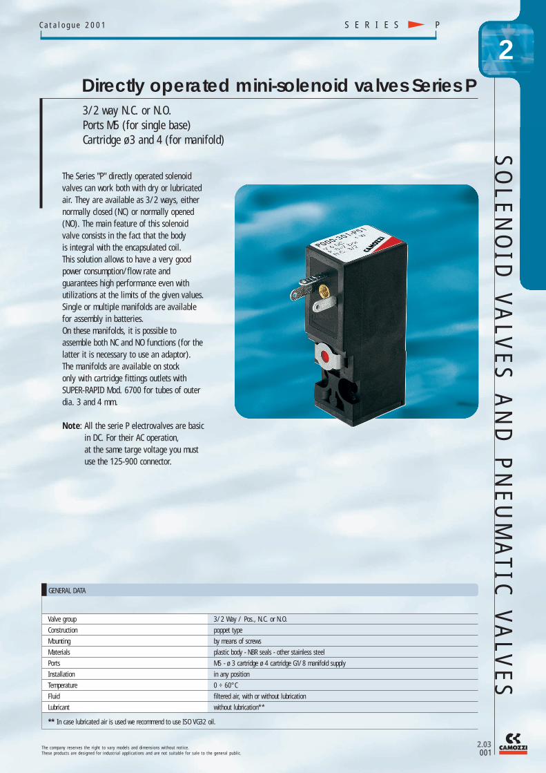
P000-303-P53
T h e c o m p a n y r e s e r v e s t h e r i g h t t o v a r y m o d e l s a n d d i m e n s i o n s w i t h o u t n o t i c e .T h e s e p r o d u c t s a r e d e s i g n e d f o r i n d u s t r i a l a p p l i c a t i o n s a n d a r e n o t s u i t a b l e f o r s a l e t o t h e g e n e r a l p u b l i c .
S E R I E SP C a t a l o g u e 2 0 0 1
2.03002
2
Operating pressure see table
Nominal pressure 6 bar
Nominal flow rate Qn 20 Nl/min. (6 bar ∆P 1 bar), Qn 30 Nl/min (6 bar ∆P 1 bar)
Nominal diameter ø 0.9 mm, ø 1.5 mm
PNEUMATIC DATA
Voltage *DC 6V, 12V, 24V, 48V
Power consumption 2 W, 1 W
Voltage tolerances ± 10%
Class of insulation class F
Protection class IP54 (with connector DIN 40050 IP65)
Duty cylce ED 100%, continuous operation
Response time 4 ÷ 5 ms
ELECTRICAL DATA
CODING OF SERIES P VALVES
SERIES P
BODY DESIGN0 = single sub-base (only M5) or interface1 = single manifold2 = double sided manifold
NUMBER OF SEGMENTS00 = interface01 = single sub-base (only M5)02 ÷ 99 = No. of segments
N° OF PORTS AND FUNCTIONS0 = not defined3 = 3 - ways N.C.4 = 3 - ways N.O.
PORTS0 = interface
*2 = M5 side ports3 = ø 3 tube side port4 = ø 4 tube side port
*6 = M5 rear ports7 = ø 3 tube rear ports8 = ø 4 tube rear ports
NOMINAL DIAMETER MAX PRESSURE
* 1 = 0,9 (1W) 7 bar (NC)7 bar (NO)
3 = ø 1,5 (2W) 7 bar (NC)5 bar (NO)
5 = ø 0,9 NA (2W) 10 bar (NC)10 bar (NO)
ENCAPSULATED MATERIALP = special thermoplastic
SOLENOID DIMENSION5 = 15 x15
SOLENOID VOLTAGE * L = 12V 50/60 Hz* B = 24V 50/60 Hz* C = 48V 50/60 Hz* D = 110V 50/60 Hz* 1 = 6V DC* 2 = 12V DC
3 = 24V DC* 4 = 48V DC* 6 = 110V DC
*on request, not available in stock.
*on request.
Note: For electrical connections use Mod. 125-800 (DC)For electrical connections use Mod. 125-900 (AC)
* Other voltages on request.
SO
LE
NO
ID V
ALV
ES
AN
D P
NE
UM
ATI
C V
ALV
ES
Mod.P001-02
T h e c o m p a n y r e s e r v e s t h e r i g h t t o v a r y m o d e l s a n d d i m e n s i o n s w i t h o u t n o t i c e .T h e s e p r o d u c t s a r e d e s i g n e d f o r i n d u s t r i a l a p p l i c a t i o n s a n d a r e n o t s u i t a b l e f o r s a l e t o t h e g e n e r a l p u b l i c .
2.03003
S E R I E S PC a t a l o g u e 2 0 0 1
2
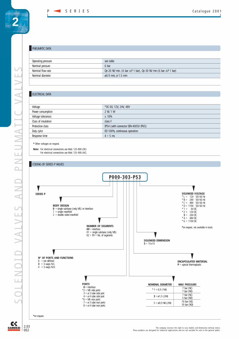
The 3/2 way solenoid valve NO can be mounted on singlesub - bases or manifold. These solenoid valves are providedwith a manual over ride for stable or monostable operation.The solenoid valve is supplied with interface seal and 2 screws.
The 3/2 way solenoid valve NC can be mounted on singlesub-bases or manifold. These solenoid valves are providedwith a manual over ride for stable or monostable operation.The solenoid valve is supplied with interface seal and 2 screws.
DIMENSIONS
Function Orifice Kv Qn PressureMod. ø mm (Nl/min) min-max barP000-305-P53 (NC) 0.9 0.3 20 0 ÷ 10P000-303-P53 (NC) 1.5 0.45 30 0 ÷ 7
3/2 way solenoid valve NC
DIMENSIONS
Function Orifice Kv Qn PressureMod. ø mm (Nl/min) min-max barP000-405-P53 (NO) 0.9 0.3 20 0 ÷ 10P000-403-P53 (NO) 1.5 0.34 23 0 ÷ 5
3/2 way solenoid valve NO
Single sub-base
Manual override
Manual override
NO Interface
Interface seal
Interface seal
SO
LE
NO
ID V
ALV
ES
AN
D P
NE
UM
ATIC
VA
LVE
S
T h e c o m p a n y r e s e r v e s t h e r i g h t t o v a r y m o d e l s a n d d i m e n s i o n s w i t h o u t n o t i c e .T h e s e p r o d u c t s a r e d e s i g n e d f o r i n d u s t r i a l a p p l i c a t i o n s a n d a r e n o t s u i t a b l e f o r s a l e t o t h e g e n e r a l p u b l i c .
S E R I E SP C a t a l o g u e 2 0 0 1
2.03004
2
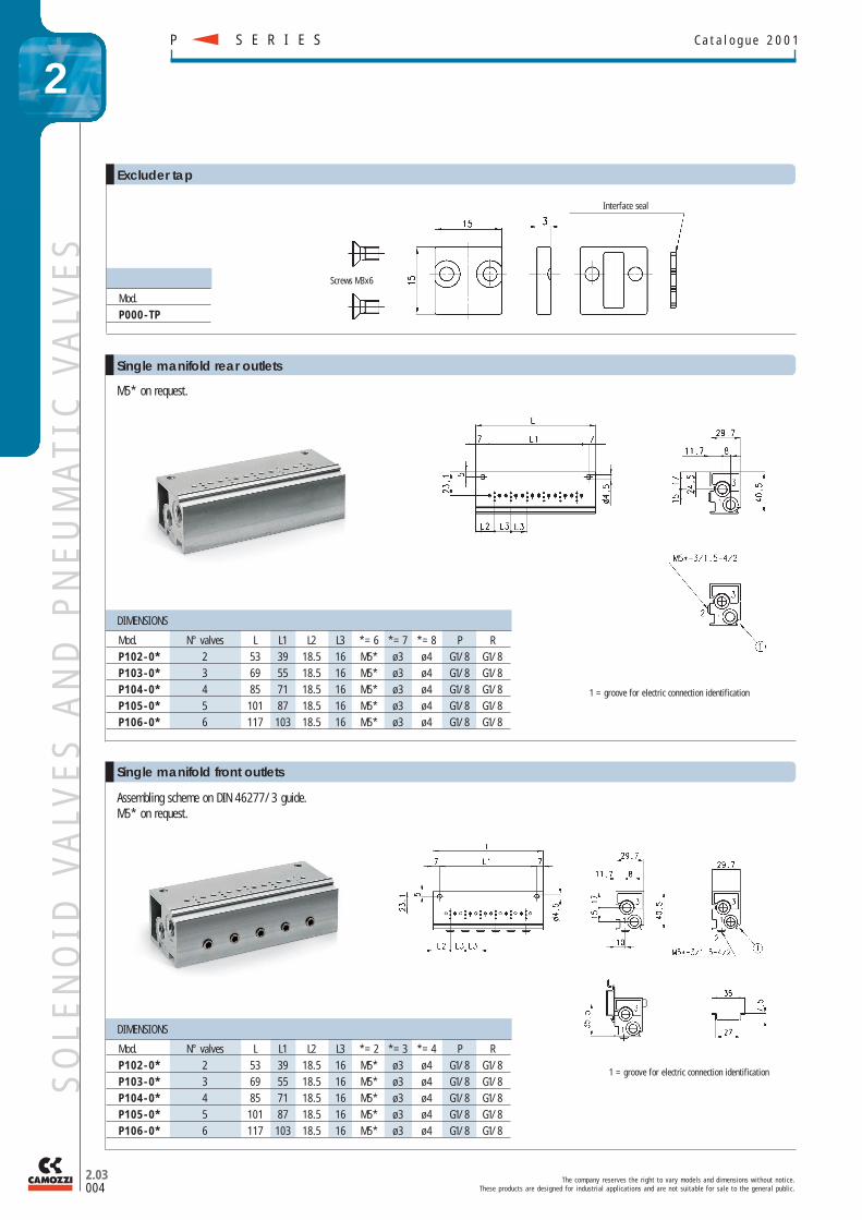
DIMENSIONS
Mod. N° valves L L1 L2 L3 *= 6 *= 7 *= 8 P RP102-0* 2 53 39 18.5 16 M5* ø 3 ø 4 G1/8 G1/8P103-0* 3 69 55 18.5 16 M5* ø 3 ø 4 G1/8 G1/8P104-0* 4 85 71 18.5 16 M5* ø 3 ø 4 G1/8 G1/8P105-0* 5 101 87 18.5 16 M5* ø 3 ø 4 G1/8 G1/8P106-0* 6 117 103 18.5 16 M5* ø 3 ø 4 G1/8 G1/8
Interface seal
Screws M3x6
Mod.P000-TP
Excluder tap
M5* on request.
Single manifold rear outlets
DIMENSIONS
Mod. N° valves L L1 L2 L3 *= 2 *= 3 *= 4 P RP102-0* 2 53 39 18.5 16 M5* ø 3 ø 4 G1/8 G1/8P103-0* 3 69 55 18.5 16 M5* ø 3 ø 4 G1/8 G1/8P104-0* 4 85 71 18.5 16 M5* ø 3 ø 4 G1/8 G1/8P105-0* 5 101 87 18.5 16 M5* ø 3 ø 4 G1/8 G1/8P106-0* 6 117 103 18.5 16 M5* ø 3 ø 4 G1/8 G1/8
Assembling scheme on DIN 46277/3 guide.M5* on request.
Single manifold front outlets
1 = groove for electric connection identification
1 = groove for electric connection identification
SO
LE
NO
ID V
ALV
ES
AN
D P
NE
UM
ATI
C V
ALV
ES
T h e c o m p a n y r e s e r v e s t h e r i g h t t o v a r y m o d e l s a n d d i m e n s i o n s w i t h o u t n o t i c e .T h e s e p r o d u c t s a r e d e s i g n e d f o r i n d u s t r i a l a p p l i c a t i o n s a n d a r e n o t s u i t a b l e f o r s a l e t o t h e g e n e r a l p u b l i c .
2.03005
S E R I E S PC a t a l o g u e 2 0 0 1
2
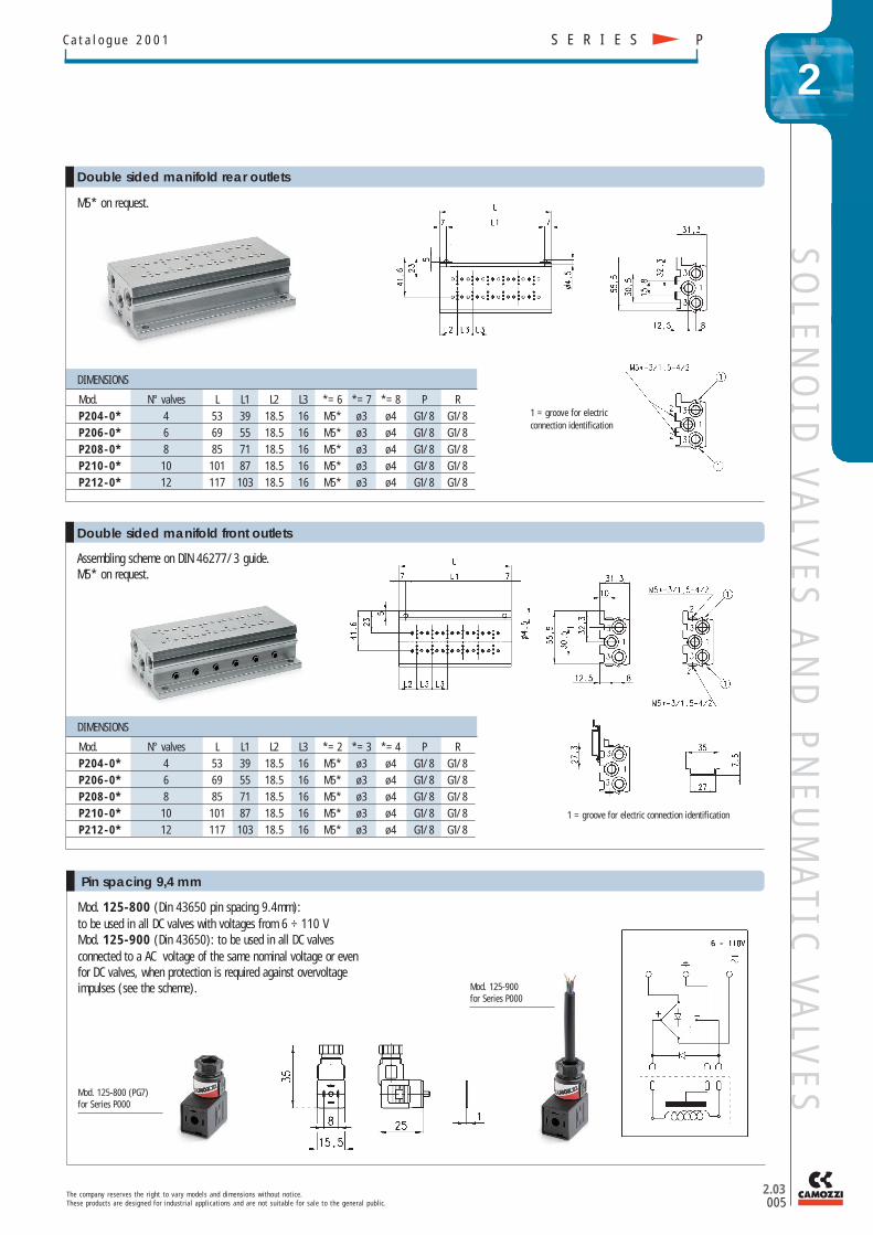
Pin spacing 9,4 mm
Mod. 125-800 (Din 43650 pin spacing 9.4mm):to be used in all DC valves with voltages from 6 ÷ 110 VMod. 125-900 (Din 43650): to be used in all DC valvesconnected to a AC voltage of the same nominal voltage or evenfor DC valves, when protection is required against overvoltageimpulses (see the scheme).
DIMENSIONS
Mod. N° valves L L1 L2 L3 *= 6 *= 7 *= 8 P RP204-0* 4 53 39 18.5 16 M5* ø 3 ø 4 G1/8 G1/8P206-0* 6 69 55 18.5 16 M5* ø 3 ø 4 G1/8 G1/8P208-0* 8 85 71 18.5 16 M5* ø 3 ø 4 G1/8 G1/8P210-0* 10 101 87 18.5 16 M5* ø 3 ø 4 G1/8 G1/8P212-0* 12 117 103 18.5 16 M5* ø 3 ø 4 G1/8 G1/8
DIMENSIONS
Mod. N° valves L L1 L2 L3 *= 2 *= 3 *= 4 P RP204-0* 4 53 39 18.5 16 M5* ø 3 ø 4 G1/8 G1/8P206-0* 6 69 55 18.5 16 M5* ø 3 ø 4 G1/8 G1/8P208-0* 8 85 71 18.5 16 M5* ø 3 ø 4 G1/8 G1/8P210-0* 10 101 87 18.5 16 M5* ø 3 ø 4 G1/8 G1/8P212-0* 12 117 103 18.5 16 M5* ø 3 ø 4 G1/8 G1/8
M5* on request.
Double sided manifold rear outlets
1 = groove for electric connection identification
1 = groove for electricconnection identification
Assembling scheme on DIN 46277/3 guide.M5* on request.
Double sided manifold front outlets
Mod. 125-900for Series P000
Mod. 125-800 (PG7)for Series P000
SO
LE
NO
ID V
ALV
ES
AN
D P
NE
UM
ATIC
VA
LVE
S


![Solenoid Valves HJE Series€¦ · 4. For double solenoid valve. Air Internal pilot type Not required 0.2~0.7 {2~7.1} [29~102] 1.05 {10.7} [152] 5 2 10 5~50 [41~122] Any](https://img.pdfslide.tips/doc/110x75/5ea556560f2e8c4b6b6e76a1/solenoid-valves-hje-series-4-for-double-solenoid-valve-air-internal-pilot-type.jpg)