Embed Size (px)
Citation preview
SCIENCE∗RESEARCH∗DEVELOPMENTNAUKA∗ISTRAŽIVANJE∗RAZVOJ
ZAVARIVANJE I ZAVARENE KONSTRUKCIJE (2/2007), str. 43-53 43
R. Ćirić, Z. Odanović, V. Grabulov, K. Raić
STRUKTURNE PROMENE KOD ROTACIONOG ZAVARIVANJA TRENJEM RAZLIČITIH ČELIKA
STRUCTURAL CHANGES AT ROTATION FRICTION WELDING OF VARIOUS STEEL TYPES
Originalni naučni rad / Original scientific paper
UDK / UDC: 620.18:621.791.1.052:669.14
Rad primljen / Paper received: Juli 2007.
Adresa autora / Author's address: Mr Radovan Ćirić, dipl. inž. met. Viša tehnička škola, Svetog Save 65, Čačak, Srbija
Dr Zoran Odanović, dipl. inž. met. Institut IMS, Bulevar vojvode Mišića 43, Beograd, Srbija Dr Vencislav Grabulov, dipl. inž. met. Vojnotehnički institut, R. Resanovića 1, Beograd, Srbija Prof. dr Karlo Raić, dipl. inž. met. Tehnološko-metalurški fakultet, Karnegijeva 4, Beograd, Srbija
Ključne reči: Rotaciono zavarivanje trenjem, čelik, mikrostruktura, EDS i SEM analiza.
Keywords: Rotational friction welding, steel, microstru-cture, EDS analysis, SEM analysis.
Izvod
Korišćenjem metoda optičke mikroskopije, kvantitativne optičke mikroskopije, SEM i EDS analize izvršena su ispitivanja strukture, kao i analiza faznog i hemijskog sastava, kod trenjem zavarenih spojeva brzoreznog čelika Č 7680 sa ugljeničnim čelikom za poboljšanje Č 1730.
Abstract By using the methods of optical microscopy, quantitative optical microscopy, SEM and EDS analysis, the tests of structure were carried out, as well as the analysis of both phase and chemical composition, of joints welded by friction of the HSS steel M-2 with carbon steel for improving 1060.
INTRODUCTION
The process of rotational friction welding with continuous drive (FW) is carried out through the following five phases [1, 2]:
(I) initial friction, (II) unstable friction, (III) stable friction, i.e. quasi-stationary phase, (IV) breaking and (V) pressing-upsetting.
The phase of stable friction (phase III) begins when the layer of considerable plasticity and small strength is spread along the whole friction plane. It is considered that in this phase the heat exchange is established, which is characterized by the dynamic heat balance between the quantity of spread heat and the heat which is transmitted to BM and the environment.
As agreed [3-5] in this phase on the friction plane, the film of melted metal is not formed, except for the cases when BMs are welded, which create low-temperature melting intermetal phases.
However, according to [5-7] in this phase in the nearest vicinity of friction plane, the layer of metal in viscous state is formed, and its shape, size and the path of circulation of particles layers of metal have not been described either qualitatively or quantitatively by now.
UVOD
Proces zavarivanja trenjem (ZT) sa kontinualnim pogonom se odvija kroz sledećih pet faza [1, 2]:
I – faza početnog trenja, II – faza nestabilnog trenja, III – faza stabilnog trenja ("kvazistacionirana" faza), IV – faza kočenja i V – faza sabijanja-prokivanja.
Faza stabilnog trenja (faza III) počinje kada se sloj visoke plastičnosti i niske čvrstoće proširi po celoj površini trenja. Smatra se da se u ovoj fazi uspostavlja razmena toplote koju karakteriše dinamička toplotna ravnoteža između količine razvijene toplote i toplote provedene u OM i okolinu.
Saglasno [3-5] u ovoj fazi na površini trenja se ne formira film istopljenog metala, izuzev u slučajevima kada se zavaruju OM koji stvaraju niskotopljive intermetalne faze. Međutim, prema [5-7] u ovoj fazi u neposrednoj blizini ravni trenja formira se sloj metala u viskoznom stanju čiji oblik, veličina i putanja kretanja čestica (slojeva) metala do sada nisu kvalitativno ni kvantitativno opisani.
EKSPERIMENTALNI DEO
Materijal i eksperimentalni podaci
Za zavarivanje su korišćeni brzorezni čelik Č 7680 iugljenični čelik za poboljšanje Č 1730 u obliku šipki
SCIENCE∗RESEARCH∗DEVELOPMENTNAUKA∗ISTRAŽIVANJE∗RAZVOJ
44 ZAVARIVANJE I ZAVARENE KONSTRUKCIJE (2/2007), str. 43-53
prečnika 10 mm, hemijskog sastava u masenim procentima i tvrdoće prema tabeli 1.
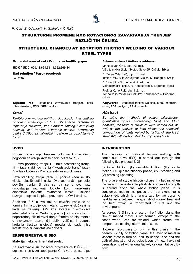
Osnovni materijali iz tabele 1 su međusobno zavareni postupkom rotacionog zavarivanja trenjem sa kontinualnim pogonom ZT), slika 1. Osnovni parametri procesa ZT u fazi trenja su: pritisak trenja Pt (MPa), vreme trenja Vt (s) i broj obrta n (u eksperimentu n=const=2850 min-1). Parametri u fazi sabijanja-prokivanja su: pritisak sabijanja Ps (MPa) i vreme sabijanja Vs (s). U eksperimentu je rotirao uzorak od čelika Č 7680.
U okviru eksperimentalnih istraživanja korišćenjem metoda optičke i kvantitativne optičke mikroskopije, elektronske mikroskopije i EDS-analize izvršeno je ispitivanje mikrostrukture i analiza hemijskog i faznog sastava u oblasti zavarenog spoja posebno u oblasti viskoznog sloja, ravni trenja i susednim zonama. Analiza je uglavnom vršena u pogledu pojava u III fazi trenja procesa ZT.
EXPERIMENTAL
Material and experimental data
The HSS M2 according to AISI and carbon heat treatable steel of 1060 according to AISI were used in the shape of specimens 10 mm diameter, the chemical compositions in the weight percentages and the hardness of which are given in Table 1. The basic materials from Table 1 are mutually welded by the procedure of rotational friction welding with continuous drive (FW), Fig. 1.
The basic parametres of FW process in the phase of friction are: friction pressure Pf (MPa), friction time Vf (s) and the number of revolutions n (in the experiment n=const=2850 min-1). The parametres in the phase of upsetting are the upsetting pressure: Pu (MPa) and upsetting time Vu (s). The specimen of steel M2 rotated in the experiment.
Slika 1: Šematski prikaz modela procesa rotacionog zavarivanja trenjem sa kontinualnim pogonom
u fazi trenja (a) i fazi sabijanja-prokivanja (b) Figure 1: Schematic presentation of model of the rotation friction welding by continuous drive
in the friction phase (a) and the upsetting phase (b)
Tabela 1: Hemijski sastav i tvrdoća osnovnih materijala
Sadržaj elemenata, mas. % Čelik
C Si Tvrdoća
HB2.5/62.5/20 Stanje
Mn Cr W Mo V S P
Č7680 0,86 / / 4,07 6,03 4,75 1,82 0,0036 0,0137 260-272 Č1730 0,63 0,194 0,82 0,0036 0,00273 / / / / /
Meko žareno
Table 1: Chemical compositions and hardness of base materials
Content of elements, mas.% Steel
C Si Mn Cr W Mo V S P Hardness HB2.5/62.5/20
State
M2 0,86 / / 4,07 6,03 4,75 1,82 0,0036 0,0137 260-272 1060 0,63 0,194 0,82 0,0036 0,00273 / / / / /
Soft annealed
SCIENCE∗RESEARCH∗DEVELOPMENTNAUKA∗ISTRAŽIVANJE∗RAZVOJ
ZAVARIVANJE I ZAVARENE KONSTRUKCIJE (2/2007), str. 43-53 45
Ispitivanje strukture, faznog i hemijskog sastava
Cilj eksperimenta je da se zapaze osnovne karakteristike mikrostrukture u Č 7680 formirane u fazi trenja procesa ZT Č 7680 sa Č 1730, objasne određene pojave i utvrdi veza između parametara procesa, mikrostrukture i osobina zavarenih spojeva.Ispitivanje je izvršeno uz korišćenje metoda optičke mikroskopije, kvantitativne optičke mikroskopije, elektronske mikroskopije i semikvantitativne (EDS) analize.
Metodom kvantitativne optičke mikroskopije izmerena je veličina austenitnog zrna u viskoznom sloju i drugim zonama u blizini pokretne ravni trenja. Merenje je izvršeno linijskom metodom na automatskom uređaju za analizu slike "Quantimet-500 MC" firme Leice uz pomoć optičkog mikroskopa.
Ispitivanje strukture trenjem zavarenih spojeva Č 7680 sa Č 1730 je izvršeno na Scanning elektronskom mikroskopu tip "JSM-5300" (proizvođač "Jeol" - Japan), a ispitivanje hemijskog sastava na istom mikroskopu uz korišćenje uređaja za EDS (Energy Disp. Spectr.) analizu tip "Link - DX 2000" (proizvođač "Oxford inst", England). Ispitivani uzorci prečnika 10 mm su čeono zavareni trenjem po režimu: Pt=80 MPa, Vt =15 s, n=2850 min-1, bez prokivanja.
REZULTATI I DISKUSIJA
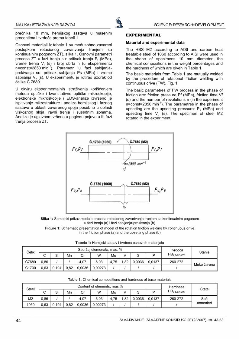
Na bazi obimnih preliminarnih ispitivanja i praćenja fenomena do kojih dolazi u fazi trenja procesa ZT ispitivane su određene pojave u karakterističnim zonama prikazanim na slici 2 [7].
Within experimental tests by using the methods of optical and quantitative optical microscopy, electronical microscopy and the EDS analysis, the testing of microstructure and the analyses of both chemical and phase composition in the area of viscous layer, the friction plane and adjoining zones are carried out. The analysis was mainly carried out regarding the occurrences in the III friction phase of FW process.
Testing of the structure, phase and chemical composition
The aim of the experiment is to establish the basic characteristics of the microstructure in M2 which is formed in the friction phase of the process FW M2 with 1060, to explain certain occurrences and to establish the relation between the parameters of the process, microstructure and the properties of the welded joints.
By method of quantitative optical microscopy the austenite grain size in viscous layer and in the other zones in the vicinity of the movable friction plane were measured.
The measurement was carried out by linear method on the automatic device for the analysis of the picture »Quantimet-500 MC« manufactured by the Leica company, with the help of the optical microscope.
The test of the structure of the welded friction joints M2 with 1060 was carried out on the Scanning electronic microscope »JSM-5300« (manufactured by »Jeol«, Japan), and the test of the chemical composition on the same microscope by using the
Slika 2: Šematski prikaz karakterističnih zona u blizini ravni trenja u III fazi trenja procesa ZT Č7680 sa Č1730: 1 - viskozni sloj, 2 - karbidna ravan (δ=0,001-0,006 mm) formirana duž ravni
trenja, 3 - sloj Č7680 navaren na Č1730, 4 - zona mešanja Č7680 i Č1730.
Figure 2: The schematic presentation of the characteristically zones in the vicinity of the friction planes in the third friction phase of the process FW M2 with 1060: 1 – viscous layer, 2 – carbide layer (δ=0,001-0,006 mm) which is formed along the friction plane, 3 – layer M2 surfaced onto
1060, 4 – mixed zone M2 and 1060.
SCIENCE∗RESEARCH∗DEVELOPMENTNAUKA∗ISTRAŽIVANJE∗RAZVOJ
46 ZAVARIVANJE I ZAVARENE KONSTRUKCIJE (2/2007), str. 43-53
device for EDS analysis, type »Link-DX 2000« (manufactured by »Oxford inst«, England). The tested specimens of 10 mm diameters were previously welded by friction according to the regime: Pf=80 MPa, Vf=15 s, n=2850 min-1, without upsetting.
n
RESULTS AND DISSCUSION
On the basis of voluminous preliminary tests and the observing of the phenomena which occur in the friction phase FW, certain occurences are tested in the characteristic zones which are shown in Fig. 2 [7].
Microstructure of surfaced layer, mixed zone and viscous layer
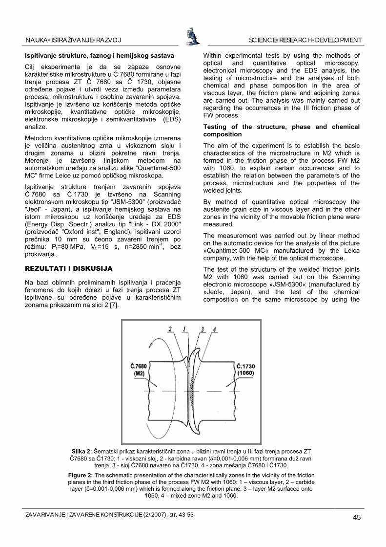
In the experiment, the change of shape and size of the layer M2 is observed, surfaced in the friction phase of the process FW onto 1060 in dependence of the friction time. The specimens are FW according to regime Pf=80 MPa, n=2850 min-1, Vf=1,5 up to 17 s. The specimens are, after the chosen time of friction, separated without upsetting. It is established that even in the initial friction phase, due to the tearing of the micro-welded joints between BMs with various heat-physical properties [4, 8], surfacing of M2 onto 1060 in the friction plane and onto 1060 extruded out of the joint occurs, zone 3 in Fig. 2, and the friction couple becomes M2, Fig.2. In addition, the greatest thicknes of the surfaced layer was measured in the central part of the specimen (at Vf≈13 s) and the same thickness is possibly the maximum possible thickness of the surfaced joint for the used BMs, the dimensions of specimens and the regime FW; the thickness of the layer is reduced while approaching to the external surface of the specimen and it is lowest on the metal extruded out of the joint zone, Fig. 3.
By metalographic testing it is established that in the during friction phase of the process FW M2 with 1060 in the layer M2 surfaced onto 1060, the zone in which the mixing of the particles of the both BMs with higher or lower degree of homogenisation is formed, zone 4 in Fig. 2. The mentioned zone, while applied the number of revolutions n=2850 min-1 and the frictio
Mikrostruktura navarenog sloja, zone mešanja i viskoznog sloja
U eksperimentu je sa ciljem analize mikrostrukture navarenog spoja praćena promena oblika i veličine sloja Č 7680 navarenog u fazi trenja procesa ZT na Č 1730 u zavisnosti od vremena trenja. Probni uzorci su ZT po režimu Pt=80 MPa, n=2850 min-1, Vt=1,5 do 17 s, pri čemu su uzorci posle odabranog vremena trenja razdvajani, bez prokivanja. Utvrđeno je da još u početnoj fazi trenja, usled kidanja mikrozavarenih spojeva između OM sa različitim toplotno-fizičkim osobinama [4, 8] dolazi do navarivanja Č 7680 na Č 1730 u ravni trenja i na Č 1730 istisnutom van spoja, zona 3 na slici 2 i par trenja postaje Č 7680, slika 2. Pri tome je najveća debljina navarenog sloja izmerena u centralnom delu uzorka (pri Vt ≈13 s) i ista verovatno, saglasno [8], predstavlja maksimalno moguću debljinu navarenog spoja za korišćene OM, dimenzije uzoraka i režim ZT; debljina sloja se smanjuje sa približavanjem obimu šipke i najmanja je na metalu istisnutom van zone spoja, slika 3.
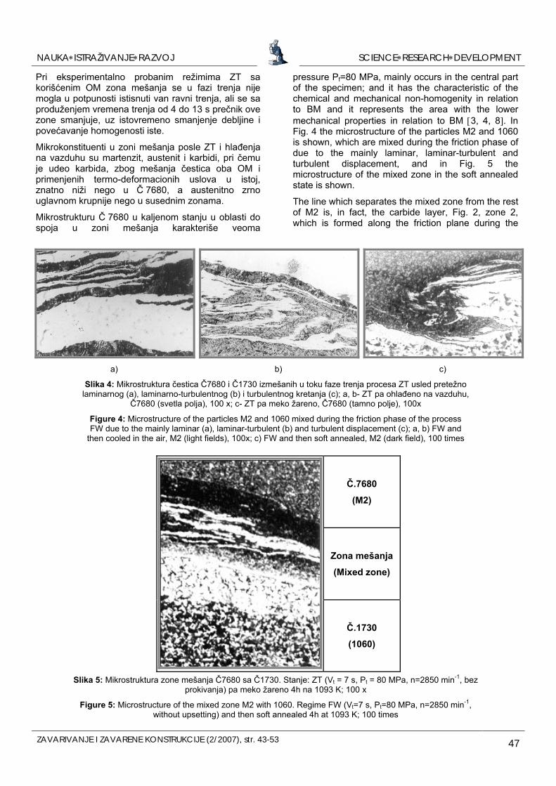
Metalografskim ispitivanjem utvrđeno je da se u fazi trenja procesa ZT Č 7680 sa Č 1730 u sloju Č 7680 navarenom na Č 1730 formira zona u kojoj dolazi do mešanja čestica oba OM, sa većim ili manjim stepenom homogenizacije, zona 4 na slici 2. Pomenuta zona se, pri primenjenom broju obrtaja (n=2850 mm-1) i pritisku trenja Pt=80 MPa, uglavnom javlja u centralnom delu šipke, odlikuje se hemijskom i mehaničkom nehomogenošću u odnosu na OM i predstavlja oblast sa slabijim mehaničkim osobinama u odnosu na OM [3, 4 i 8]. Na slici 4 je prikazana mikrostruktura čestica Č 7680 i Č 1730 izmešanih u toku faze trenja procesa ZT usled pretežno laminarnog, laminarno-turbulentnog i turbulentnog kretanja, a na slici 5 mikrostruktura zone mešanja u meko žarenom stanju.
Linija koja odvaja zonu mešanja od ostalog dela Č 7680 je ustvari karbidni sloj, zona 2 na slici 2, koji se formira uz ravan trenja u fazi trenja i u slučaju ZT sa neodgovarajućim režimom može predstavljati makroskopsku grešku (neprovar).
Slika 3: Mikrostruktura sloja Č7680 navarenog u fazi trenja na Č1730 pa istisnutog van ravni trenja, 200x Figure 3: Microstructure of the layer M2 surfaced in the friction phase onto 1060 and then extruded
out of the friction plane, 200 times
SCIENCE∗RESEARCH∗DEVELOPMENTNAUKA∗ISTRAŽIVANJE∗RAZVOJ
ZAVARIVANJE I ZAVARENE KONSTRUKCIJE (2/2007), str. 43-53 47
pressure Pf=80 MPa, mainly occurs in the central part of the specimen; and it has the characteristic of the chemical and mechanical non-homogenity in relation to BM and it represents the area with the lower mechanical properties in relation to BM [3, 4, 8]. In Fig. 4 the microstructure of the particles M2 and 1060 is shown, which are mixed during the friction phase of due to the mainly laminar, laminar-turbulent and turbulent displacement, and in Fig. 5 the microstructure of the mixed zone in the soft annealed state is shown.
The line which separates the mixed zone from the rest of M2 is, in fact, the carbide layer, Fig. 2, zone 2, which is formed along the friction plane during the
a) b) c)
Slika 4: Mikrostruktura čestica Č7680 i Č1730 izmešanih u toku faze trenja procesa ZT usled pretežno laminarnog (a), laminarno-turbulentnog (b) i turbulentnog kretanja (c); a, b- ZT pa ohlađeno na vazduhu,
Č7680 (svetla polja), 100 x; c- ZT pa meko žareno, Č7680 (tamno polje), 100x
Figure 4: Microstructure of the particles M2 and 1060 mixed during the friction phase of the process FW due to the mainly laminar (a), laminar-turbulent (b) and turbulent displacement (c); a, b) FW and
then cooled in the air, M2 (light fields), 100x; c) FW and then soft annealed, M2 (dark field), 100 times
Č.7680
(M2)
Zona mešanja
(Mixed zone)
Č.1730
(1060)
Slika 5: Mikrostruktura zone mešanja Č7680 sa Č1730. Stanje: ZT (Vt = 7 s, Pt = 80 MPa, n=2850 min-1, bez prokivanja) pa meko žareno 4h na 1093 K; 100 x
Figure 5: Microstructure of the mixed zone M2 with 1060. Regime FW (Vt=7 s, Pt=80 MPa, n=2850 min-1, without upsetting) and then soft annealed 4h at 1093 K; 100 times
Pri eksperimentalno probanim režimima ZT sa korišćenim OM zona mešanja se u fazi trenja nije mogla u potpunosti istisnuti van ravni trenja, ali se sa produženjem vremena trenja od 4 do 13 s prečnik ove zone smanjuje, uz istovremeno smanjenje debljine i povećavanje homogenosti iste.
Mikrokonstituenti u zoni mešanja posle ZT i hlađenja na vazduhu su martenzit, austenit i karbidi, pri čemu je udeo karbida, zbog mešanja čestica oba OM i primenjenih termo-deformacionih uslova u istoj, znatno niži nego u Č 7680, a austenitno zrno uglavnom krupnije nego u susednim zonama.
Mikrostrukturu Č 7680 u kaljenom stanju u oblasti do spoja u zoni mešanja karakteriše veoma
SCIENCE∗RESEARCH∗DEVELOPMENTNAUKA∗ISTRAŽIVANJE∗RAZVOJ
48 ZAVARIVANJE I ZAVARENE KONSTRUKCIJE (2/2007), str. 43-53
friction phase and in case of FW with the unsuitable regime it can represent the macroscopic error.
During the experimentally tested regimes FW with, the mixed zone could not, during the friction phase, completely extract out of the friction plane, but with the extension of friction time from 4 up to 13 s, the diameter and the thickness of this zone is reduced, and the homogeneity of the same increased. The microconstituents in the mixed zone after FW and after cooling in the air are martenzite, austenite and carbides, at which the share of carbides due to the mixing of particles of both BMs and the applied thermo-deformational conditions in the same is significantly lower than in M2, and the austenite grain is mainly bigger than in the adjacent zones.
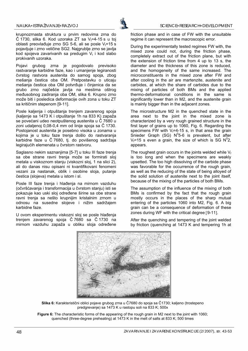
The microstructure M2 in the quenched state in the area next to the joint in the mixed zone is characterized by a very rough grained structure in the first layer of grains up to 1060, Fig. 6. Regarding the specimens FW with Vf=4-15 s, in that area the grain Snieder Graph (SG) N05-6 is prevalent, but after Vf=15 s even a grain, the size of which is SG N02, appears.
The roughest grain occurs in the joints welded while Vfis too long and when the specimens are weakly upsetted. The too high dissolving of the carbide phase was favorable for the occurrence of the rough grain, as well as the reducing of the state of being alloyed of the solid solution of austenite next to the joint itself, because of the mixing of the particles of both BMs.
The assumption of the influence of the mixing of both BMs is confirmed by the fact that the rough grain mostly occurs in the places of the sharp mutual entering of the particles 1060 into M2, Fig. 6. A big grain can be a consequence of deformation of these zones during WF with the critical degree [9-11].
After the quenching and tempering of the joint welded by friction (quenching at 1473 K and tempering 1h at
krupnozrnasta struktura u prvim redovima zrna do Č 1730, slika 6. Kod uzoraka ZT sa Vt=4-15 s u toj oblasti preovlađuje zrno SG 5-6, ali se posle Vt=15 s pojavljuje i zrno veličine SG2. Najgrublje zrno se javlja kod spojeva zavarivanih sa predugim Vt i kod slabo prokivanih uzoraka.
Pojavi grubog zrna je pogodovalo previsoko rastvaranje karbidne faze, kao i umanjenje legiranosti čvrstog rastvora austenita do samog spoja, zbog mešanja čestica oba OM. Pretpostavku o uticaju mešanja čestica oba OM potvrđuje i činjenica da se grubo zrno najčešće javlja na mestima oštrog međusobnog zadiranja oba OM, slika 6. Krupno zrno može biti i posledica deformacije ovih zona u toku ZT sa kritičnim stepenom [9-11].
Posle kaljenja i otpuštanja trenjem zavarenog spoja (kaljenje sa 1473 K i otpuštanje 1h na 833 K) zapaža se povećani udeo neotpuštenog austenita u Č 7680 u zoni udaljenoj 0,08-0,4 mm od linije spoja sa Č 1730. Postojanost austenita je posebno visoka u zonama u kojima je u toku faze trenja došlo do rastvaranja karbidne faze u Č 7680, tj. do povišenog sadržaja legirajućih elemenata u čvrstom rastvoru.
Saglasno nekim saznanjima [5-7] u toku III faze trenja sa obe strane ravni trenja može se formirati sloj metala u viskoznom stanju (viskozni sloj, 1 na slici 2), ali do danas nisu opisani ni kvantifikovani fenomeni vezani za nastanak, oblik i osobine sloja, putanje čestica (slojeva) metala u istom i sl.
Posle III faze trenja i hlađenja na mirnom vazduhu (očvršćavanja i transformacija u čvrstom stanju) isti se pokazuje kao uski sloj određene širine sa obe strane ravni trenja sa nešto krupnijim kristalnim zrnom u odnosu na susedne slojeve i nižim sadržajem karbidne faze.
U ovom eksperimentu viskozni sloj se posle hlađenja trenjem zavarenog spoja Č 7680 sa Č 1730 na mirnom vazduhu zapaža u obliku sloja određene
Slika 6: Karakteristični oblici pojave grubog zrna u Č7680 do spoja sa Č1730; kaljeno (trostepeno
predgrevanje) sa 1473 K u rastopu soli na 833 K; 500x
Figure 6: The characteristic forms of the appearing of the rough grain in M2 next to the joint with 1060; quenched (three-degree preheating) at 1473 K in the melt of salts at 833 K; 500 times
SCIENCE∗RESEARCH∗DEVELOPMENTNAUKA∗ISTRAŽIVANJE∗RAZVOJ
ZAVARIVANJE I ZAVARENE KONSTRUKCIJE (2/2007), str. 43-53 49
833 K), the increased share of the rest austenite in M2 in the zone which is 0,08-0,4 mm distant from the joint line with 1060 is observed.
The stability of the austenite is especially high in the zones in which, during the friction phase, the almost complete dissolving of carbide phase in M2 occurred, that is, when the increased content of the alloying elements in the solid solution occurred.
In accordance with literature [5-7] during the III friction phase on both sides of the friction plane, a layer of metal in viscous state can be formed (viscous layer, 1 in Fig. 2). However, the quantified phenomena
širine formiranog u oblasti ravni trenja i često je praćen pojavom karbidne ravni, najčešće u centralnom delu šipke.
Viskozni sloj je, pogotovu u centralnim delovima šipke podeljen jasno izraženom ravni trenja (rotaciona ravan) na dva dela. Uz ravan trenja sa strane Č 1730, koji je rotirao, često se formira karbidna sloj, tj. karbidna ravan.
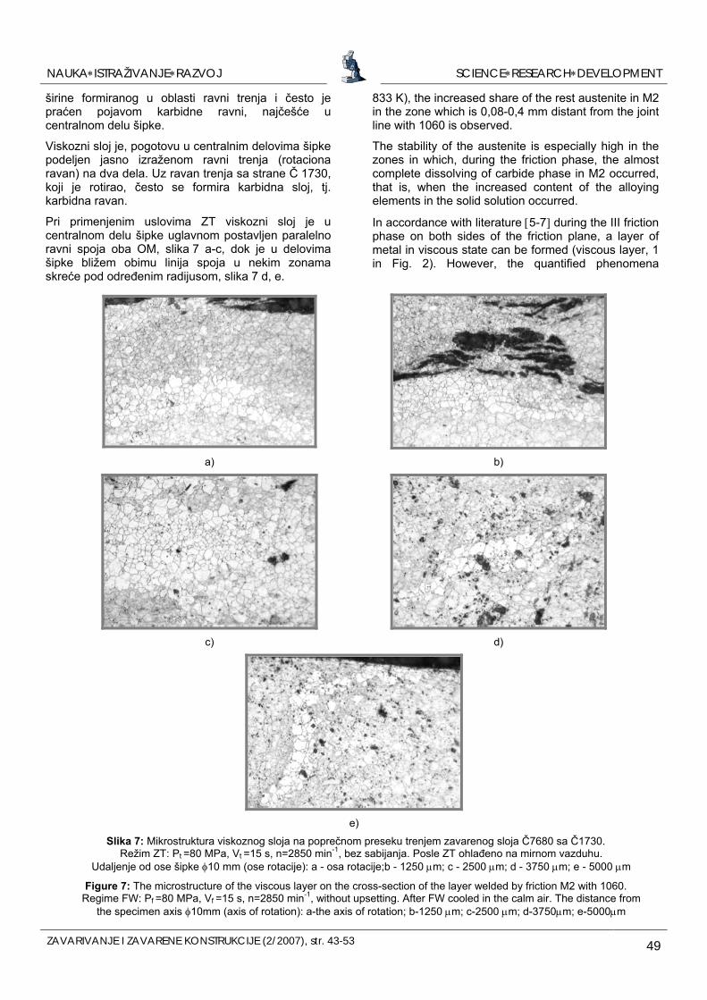
Pri primenjenim uslovima ZT viskozni sloj je u centralnom delu šipke uglavnom postavljen paralelno ravni spoja oba OM, slika 7 a-c, dok je u delovima šipke bližem obimu linija spoja u nekim zonama skreće pod određenim radijusom, slika 7 d, e.
a) b)
c) d)
e)
Slika 7: Mikrostruktura viskoznog sloja na poprečnom preseku trenjem zavarenog sloja Č7680 sa Č1730. Režim ZT: Pt =80 MPa, Vt =15 s, n=2850 min-1, bez sabijanja. Posle ZT ohlađeno na mirnom vazduhu.
Udaljenje od ose šipke φ10 mm (ose rotacije): a - osa rotacije;b - 1250 μm; c - 2500 μm; d - 3750 μm; e - 5000 μm
Figure 7: The microstructure of the viscous layer on the cross-section of the layer welded by friction M2 with 1060. Regime FW: Pf =80 MPa, Vf =15 s, n=2850 min-1, without upsetting. After FW cooled in the calm air. The distance from
the specimen axis φ10mm (axis of rotation): a-the axis of rotation; b-1250 μm; c-2500 μm; d-3750μm; e-5000μm
SCIENCE∗RESEARCH∗DEVELOPMENTNAUKA∗ISTRAŽIVANJE∗RAZVOJ
50 ZAVARIVANJE I ZAVARENE KONSTRUKCIJE (2/2007), str. 43-53
e u
Ovo ukazuje da su u fazi trenja, pored preovladajućeg rotacionog i laminarnog kretanja viskoznog sloja postojale i zone u kojima je dolazilo i do strujanja mase viskoznog metala i po nekom drugom mehanizmu.
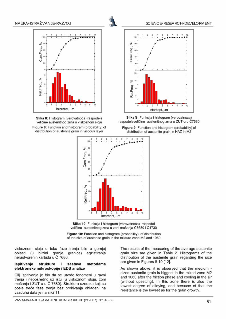
Merenje veličine austenitnog zrna
Veličina austenitnog zrna izrazito zavisi od parametara procesa i ima veliki uticaj na osobine zavarenih spojeva. Linijskom analizom izmerena je srednja veličina i raspodela austenitnog zrna posle treće faze trenja procesa ZT u viskoznom sloju, ZUT-u u Č 7680 i zoni mešanja Č 7680 i Č 1730 (Pt=80 MPa, Vt=15 s, n=2850 min-1, bez prokivanja).
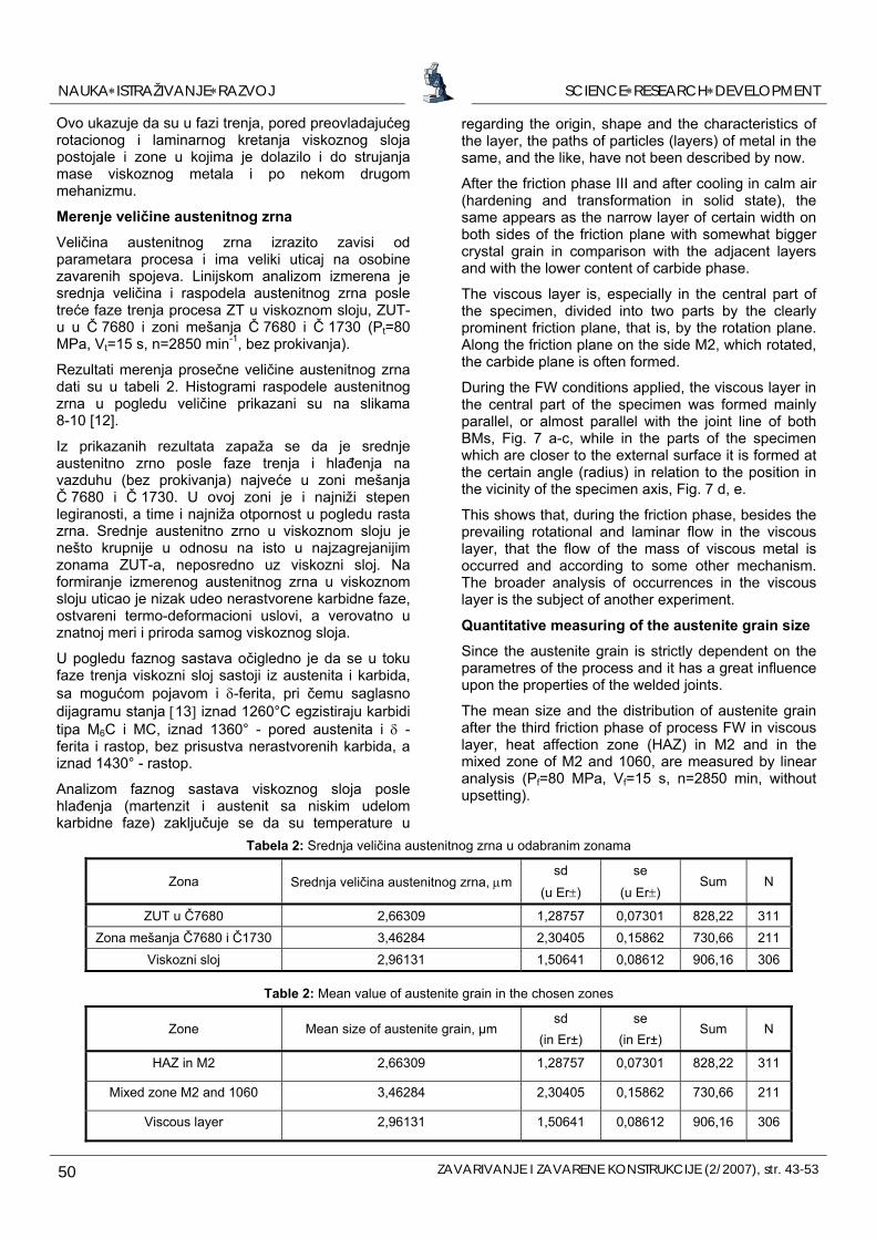
Rezultati merenja prosečne veličine austenitnog zrna dati su u tabeli 2. Histogrami raspodele austenitnog zrna u pogledu veličine prikazani su na slikama 8-10 [12].
Iz prikazanih rezultata zapaža se da je srednje austenitno zrno posle faze trenja i hlađenja na vazduhu (bez prokivanja) najveće u zoni mešanja Č 7680 i Č 1730. U ovoj zoni je i najniži stepen legiranosti, a time i najniža otpornost u pogledu rasta zrna. Srednje austenitno zrno u viskoznom sloju je nešto krupnije u odnosu na isto u najzagrejanijim zonama ZUT-a, neposredno uz viskozni sloj. Na formiranje izmerenog austenitnog zrna u viskoznom sloju uticao je nizak udeo nerastvorene karbidne faze, ostvareni termo-deformacioni uslovi, a verovatno u znatnoj meri i priroda samog viskoznog sloja.
U pogledu faznog sastava očigledno je da se u toku faze trenja viskozni sloj sastoji iz austenita i karbida, sa mogućom pojavom i δ-ferita, pri čemu saglasno dijagramu stanja [13] iznad 1260°C egzistiraju karbidi tipa M6C i MC, iznad 1360° - pored austenita i δ -ferita i rastop, bez prisustva nerastvorenih karbida, a iznad 1430° - rastop.
regarding the origin, shape and the characteristics of the layer, the paths of particles (layers) of metal in the same, and the like, have not been described by now.
After the friction phase III and after cooling in calm air (hardening and transformation in solid state), the same appears as the narrow layer of certain width on both sides of the friction plane with somewhat bigger crystal grain in comparison with the adjacent layers and with the lower content of carbide phase.
The viscous layer is, especially in the central part of the specimen, divided into two parts by the clearly prominent friction plane, that is, by the rotation plane. Along the friction plane on the side M2, which rotated, the carbide plane is often formed.
Analizom faznog sastava viskoznog sloja posle hlađenja (martenzit i austenit sa niskim udelom karbidne faze) zaključuje se da su temperatur
During the FW conditions applied, the viscous layer in the central part of the specimen was formed mainly parallel, or almost parallel with the joint line of both BMs, Fig. 7 a-c, while in the parts of the specimen which are closer to the external surface it is formed at the certain angle (radius) in relation to the position in the vicinity of the specimen axis, Fig. 7 d, e.
This shows that, during the friction phase, besides the prevailing rotational and laminar flow in the viscous layer, that the flow of the mass of viscous metal is occurred and according to some other mechanism. The broader analysis of occurrences in the viscous layer is the subject of another experiment.
Quantitative measuring of the austenite grain size
Since the austenite grain is strictly dependent on the parametres of the process and it has a great influence upon the properties of the welded joints.
The mean size and the distribution of austenite grain after the third friction phase of process FW in viscous layer, heat affection zone (HAZ) in M2 and in the mixed zone of M2 and 1060, are measured by linear analysis (Pf=80 MPa, Vf=15 s, n=2850 min, without upsetting).
Tabela 2: Srednja veličina austenitnog zrna u odabranim zonama
Zona sd
(u Er±) Srednja veličina austenitnog zrna, μm
se
(u Er±) Sum N
ZUT u Č7680 2,66309 1,28757 0,07301 828,22 311 Zona mešanja Č7680 i Č1730 3,46284 2,30405 0,15862 730,66 211
Viskozni sloj 2,96131 1,50641 0,08612 906,16 306
Table 2: Mean value of austenite grain in the chosen zones
Zone Mean size of austenite grain, μm sd
(in Er±) se
(in Er±) Sum N
HAZ in M2 2,66309 1,28757 0,07301 828,22 311
Mixed zone M2 and 1060 3,46284 2,30405 0,15862 730,66 211
Viscous layer 2,96131 1,50641 0,08612 906,16 306
SCIENCE∗RESEARCH∗DEVELOPMENTNAUKA∗ISTRAŽIVANJE∗RAZVOJ
ZAVARIVANJE I ZAVARENE KONSTRUKCIJE (2/2007), str. 43-53 51
viskoznom sloju u toku faze trenja bile u gornjoj oblasti (u blizini gornje granice) egzistiranja nerastvorenih karbida u Č 7680.
Ispitivanje strukture i sastava metodama elektronske mikroskopije i EDS analize
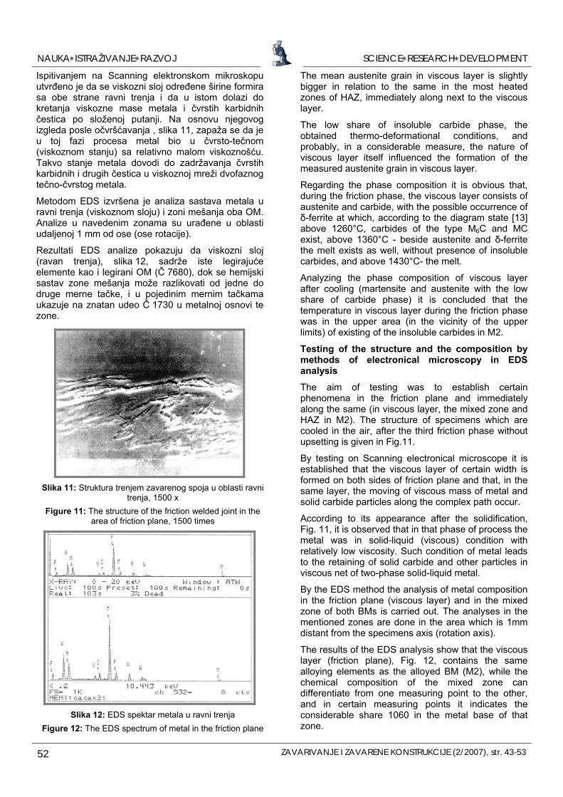
Cilj ispitivanja je bio da se utvrde fenomeni u ravni trenja i neposredno uz istu (u viskoznom sloju, zoni mešanja i ZUT-u u Č 7680). Struktura uzoraka koji su posle treće faze trenja bez prokivanja ohlađeni na vazduhu data je na slici 11.
0 1 2 3 4 5 6 7 8 9 100
5
10
15
Rel
.Fre
q., %
Intercept, μm
0
20
40
60
80
1000 1 2 3 4 5 6 7 8 9 10
Cum
.Fre
q., %
0 1 2 3 4 5 6 7 8 9 100
5
10
15
20
Rel
.Fre
q., %
Intercept, μm
0
20
40
60
80
1000 1 2 3 4 5 6 7 8 9 10
Cum
.Fre
q., %
Slika 8: Histogram (verovatnoća) raspodele veličine austenitnog zrna u viskoznom sloju
Figure 8: Function and histogram (probability) of distribution of austenite grain in viscous layer
Slika 9: Funkcija i histogram (verovatnoća) raspodeleveličine austenitnog zrna u ZUT-u u Č7680
Figure 9: Function and histogram (probability) of distribution of austenite grain in HAZ in M2
0 1 2 3 4 5 6 7 8 9 100
5
10
15
Rel
.Fre
q., %
Intercept, μm
0
20
40
60
80
1000 1 2 3 4 5 6 7 8 9 10
Cum
.Fre
q., %
Slika 10: Funkcija i histogram (verovatnoća) raspodel
veličine austenitnog zrna u zoni mešanja Č7680 i Č1730
Figure 10: Function and histogram (probability) of distribution of the size of austenite grain in the mixture zone M2 and 1060
The results of the measuring of the average austenite grain size are given in Table 2. Histograms of the distribution of the austenite grain regarding the size are given in Figures 8-10 [12].
As shown above, it is observed that the medium -sized austenite grain is biggest in the mixed zone M2 and 1060 after the friction phase and cooling in the air (without upsetting). In this zone there is also the lowest degree of alloying, and because of that the resistance is the lowest as for the grain growth.
SCIENCE∗RESEARCH∗DEVELOPMENTNAUKA∗ISTRAŽIVANJE∗RAZVOJ
52 ZAVARIVANJE I ZAVARENE KONSTRUKCIJE (2/2007), str. 43-53
Ispitivanjem na Scanning elektronskom mikroskopu utvrđeno je da se viskozni sloj određene širine formira sa obe strane ravni trenja i da u istom dolazi do kretanja viskozne mase metala i čvrstih karbidnih čestica po složenoj putanji. Na osnovu njegovog izgleda posle očvršćavanja , slika 11, zapaža se da je u toj fazi procesa metal bio u čvrsto-tečnom (viskoznom stanju) sa relativno malom viskoznošću. Takvo stanje metala dovodi do zadržavanja čvrstih karbidnih i drugih čestica u viskoznoj mreži dvofaznog tečno-čvrstog metala.
Slika 11: Struktura trenjem zavarenog spoja u oblasti ravni
trenja, 1500 x Figure 11: The structure of the friction welded joint in the
area of friction plane, 1500 times
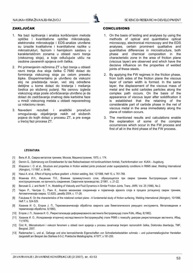
Slika 12: EDS spektar metala u ravni trenja
Figure 12: The EDS spectrum of metal in the friction plane
Metodom EDS izvršena je analiza sastava metala u ravni trenja (viskoznom sloju) i zoni mešanja oba OM. Analize u navedenim zonama su urađene u oblasti udaljenoj 1 mm od ose (ose rotacije).
Rezultati EDS analize pokazuju da viskozni sloj (ravan trenja), slika 12, sadrže iste legirajuće elemente kao i legirani OM (Č 7680), dok se hemijski sastav zone mešanja može razlikovati od jedne do druge merne tačke, i u pojedinim mernim tačkamaukazuje na znatan udeo Č 1730 u metalnoj osnovi te zone.
The mean austenite grain in viscous layer is slightly bigger in relation to the same in the most heated zones of HAZ, immediately along next to the viscous layer.
The low share of insoluble carbide phase, the obtained thermo-deformational conditions, and probably, in a considerable measure, the nature of viscous layer itself influenced the formation of the measured austenite grain in viscous layer.
Regarding the phase composition it is obvious that, during the friction phase, the viscous layer consists of austenite and carbide, with the possible occurrence of δ-ferrite at which, according to the diagram state [13] above 1260°C, carbides of the type M6C and MC exist, above 1360°C - beside austenite and δ-ferrite the melt exists as well, without presence of insoluble carbides, and above 1430°C- the melt.
Analyzing the phase composition of viscous layer after cooling (martensite and austenite with the low share of carbide phase) it is concluded that the temperature in viscous layer during the friction phase was in the upper area (in the vicinity of the upper limits) of existing of the insoluble carbides in M2.
Testing of the structure and the composition by methods of electronical microscopy in EDS analysis
The aim of testing was to establish certain phenomena in the friction plane and immediately along the same (in viscous layer, the mixed zone and HAZ in M2). The structure of specimens which are cooled in the air, after the third friction phase without upsetting is given in Fig.11.
By testing on Scanning electronical microscope it is established that the viscous layer of certain width is formed on both sides of friction plane and that, in the same layer, the moving of viscous mass of metal and solid carbide particles along the complex path occur.
According to its appearance after the solidification, Fig. 11, it is observed that in that phase of process the metal was in solid-liquid (viscous) condition with relatively low viscosity. Such condition of metal leads to the retaining of solid carbide and other particles in viscous net of two-phase solid-liquid metal.
By the EDS method the analysis of metal composition in the friction plane (viscous layer) and in the mixed zone of both BMs is carried out. The analyses in the mentioned zones are done in the area which is 1mm distant from the specimens axis (rotation axis).
The results of the EDS analysis show that the viscous layer (friction plane), Fig. 12, contains the same alloying elements as the alloyed BM (M2), while the chemical composition of the mixed zone can differentiate from one measuring point to the other, and in certain measuring points it indicates the considerable share 1060 in the metal base of that zone.
SCIENCE∗RESEARCH∗DEVELOPMENTNAUKA∗ISTRAŽIVANJE∗RAZVOJ
ZAVARIVANJE I ZAVARENE KONSTRUKCIJE (2/2007), str. 43-53 53
CONCLUSIONS ZAKLJUČAK
1. On the basis of testing and analyses by using the methods of optical and quantitative optical microscopy, electronical microscopy and the EDS analyses, certain prominent qualitative and quantitative differences in microstructure, both phase and chemical composition in the characteristic zone in the area of friction plane (viscous layer) are observed and which have the decisive influence on the properties of welded joints of these steels.
1. Na bazi ispitivanja i analiza korišćenjem metoda optičke i kvantitativne optičke mikroskopije, elektronske mikroskopije i EDS-analize utvrđene su izrazite kvalitativne i kvantitativne razlike u mikrostrukturi, faznom i hemijskom sastavu u karakterističnim zonama u oblasti ravni trenja (viskoznog sloja), a koje odlučujuće utiču na osobine zavarenih spojeva ovih čelika.
2. Pri primenjenim režimima ZT u fazi trenja u oblasti ravni trenja dva sloja čelika Č 7680 dolazi do formiranja viskoznog sloja po celom preseku šipke. Eksperimentalno je utvrđeno da viskozni sloj ne predstavlja ravan, već sloj određene debljine u kome dolazi do kretanja i mešanja čestica po složenoj putanji. Na osnovu izgleda viskoznog sloja posle očvršćavanja utvrđeno je da dolazi do zadržavanja znatnog dela karbidne faze u mreži viskoznog metala u oblasti neposrednog uz rotacionu ravan.
2. By applying the FW regimes in the friction phase, from both sides of the friction plane the viscous layer of certain width is formed. In the same layer, the displacement of the viscous mass of metal and the solid carbides particles along the complex path occurs. On the basis of the appearance of viscous layer after solidification it is established that the retaining of the considerable part of carbide phase in the net of viscous metal in the area immediately along the plane of rotation occurs. 3. Navedeni rezultati i analitički proračuni
omogućavaju objašnjenje nekih od složenih pojava do kojih dolazi u procesu ZT, a pre svega u trećoj fazi procesa ZT.
3. The mentioned results and calculations enable the explanation of some of the complex occurrences which occur in the FW process and first of all in the third phase of the FW process.
LITERATURA
[1] Виль И. В., Сварка металлов трением, Москов, Машиностроение, 1970, с. 174. [2] Dennin G., Optimierung von Einstellwerten fur das Reibschweissen mit kontinuerlichem Antrieb, Fachinformation von KUKA – Augsburg. [3] Khazanov I. O. et al., Structure and properties in friction welded joints produced under superplasticity conditions in R6M5 steel, Welding International
(Abington), 11/1997, s. 64-66.. [4] Hasui A. et al., Effect of faying surface gradient u friction welding, Ibid, 12/1998, Heft 10, s. 761-768. [5] Фомичев И.Н., Имшенник П.К., Влияние промежуточного слоя, образующегося при сварке трением быстрорежущих сталей с
конструкционными, на прочность соединения, Сварочное производство, 2/1981, с. 21-22. [6] Benzsak G. J. and North T. H., Modelling of Viskosity and Fluid Dynamics in Similar Friction Joints, Trans. JWRI, Vol. 25 (1996), No.2. [7] Чирич Р., Чантрак С., Раич К., Анализ механизма соединенија и појавленија вјазкога слоја в процесе ротационој сварки трением,
Автоматическаја сварка, 12 (620), декабр 2004, с. 17–26. [8] Fukukasa K: On the characteristics of the rotational contact plane - A fundamental study of friction surfacing, Welding International (Abington), 10/1996,
Heft 7, s. 524-529. [9] Хазанов И. О., Егоров Ј. П., Термомеханическаја обработка сварнога шва биметалическога режущего инструмента, Металоведение и
термическаја обработка, 5(1980). [10] Егоров Ј. П., Хазанов И. О., Рекристализација деформированога австенита бистрорежущеј стали Р6М5, Ибид, 8(1982). [11] Хазанов И. О., Иследованије вторичној наследствености бистрорежушћеј стали Р6М5 с помошћу диаграм рекристализации австенита, Ибид,
11(1976). [12] Ćirić R., Mikrostrukturni i viskozni fenomeni u oblasti ravni spajanja u procesu zavarivanja trenjem raznorodnih čelika, Doktorska disertacija, TMF,
Beograd, 2007. [13] Rademacher L. und al., Gefuege und eine kennzeichende Eigenschaften von Schnellarbeitsstahlen schmelz – und pulvermetallurgischer Herstellen
dargestellt am Beispiel des Stahless 6-5-2, Praktische Metallographie, 4/1977, s 181-200.