Embed Size (px)
Citation preview
Thesis Proposal
Student Health Center Penn State University
Prepared By: Jacob Brambley (Structural Option) Prepared For: Dr. Richard Behr
Jacob Brambley Student Health Center Structural Option Dr. Richard Behr
Page 2 of 14
Table of Contents Executive Summary …………………………………………………………………………………………..3 Introduction ………………………………………………………………………………………………………4 Structural Systems ………………………………………………………………………………………….…5
Foundation …………………………………………………………………………………….……...5 Floor System/Beams ………………………………………………………………………..…….5 Columns …………………………………………………………………………………………..…….6 Roof/Penthouse Level ……………………………………………………………………..…….6 Lateral System …………………………………………………………………………………..…..7 Problem Statement ……………………………………………………………………..……………..…….10 Proposed Solution ………………………………………………………………………………..…………..10 Solution Method ……………………………………………………………………………………………….10 Breadth Topics ……..……………………………………………………………………………………….....11 Tasks and Tools …………………………………………………………………………………………..…….12 Replacement Concrete System ……………………………..………………………..…….12 Breadth Topics …..……………………….………………………..……………………………….13 Schedule ….…………………………………………………………………………………..………...…………14
Jacob Brambley Student Health Center Structural Option Dr. Richard Behr
Page 3 of 14
Executive Summary
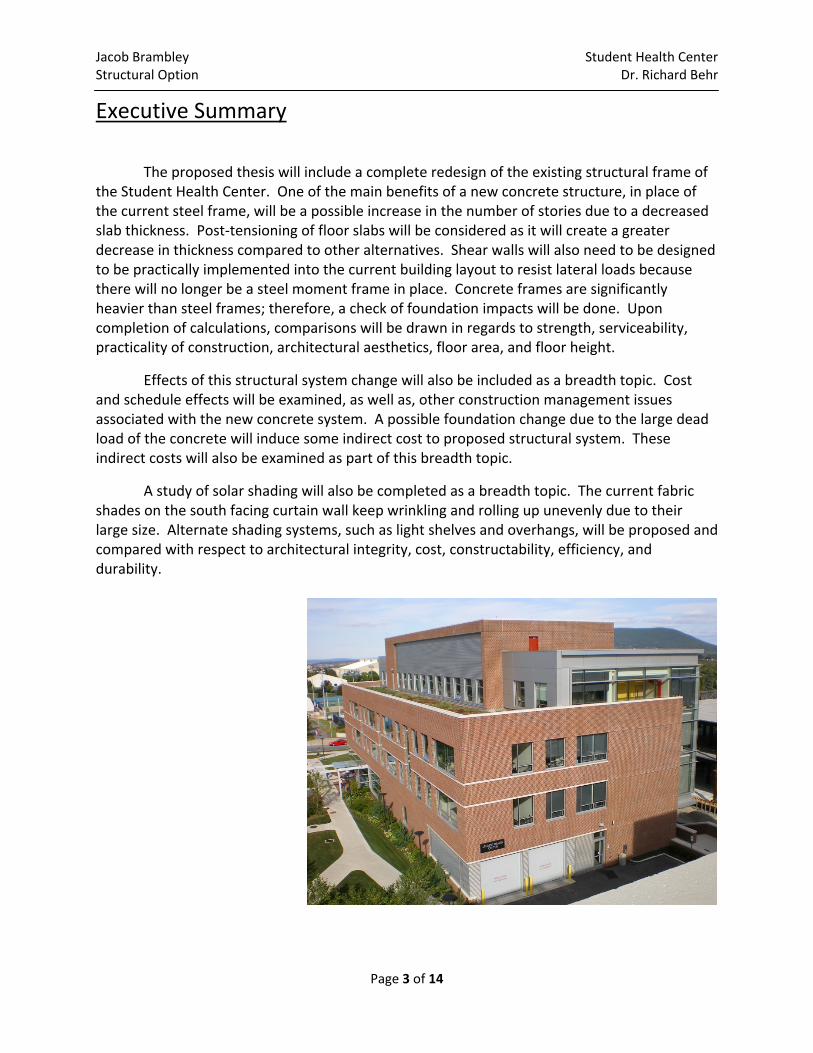
The proposed thesis will include a complete redesign of the existing structural frame of the Student Health Center. One of the main benefits of a new concrete structure, in place of the current steel frame, will be a possible increase in the number of stories due to a decreased slab thickness. Post‐tensioning of floor slabs will be considered as it will create a greater decrease in thickness compared to other alternatives. Shear walls will also need to be designed to be practically implemented into the current building layout to resist lateral loads because there will no longer be a steel moment frame in place. Concrete frames are significantly heavier than steel frames; therefore, a check of foundation impacts will be done. Upon completion of calculations, comparisons will be drawn in regards to strength, serviceability, practicality of construction, architectural aesthetics, floor area, and floor height.
Effects of this structural system change will also be included as a breadth topic. Cost and schedule effects will be examined, as well as, other construction management issues associated with the new concrete system. A possible foundation change due to the large dead load of the concrete will induce some indirect cost to proposed structural system. These indirect costs will also be examined as part of this breadth topic.
A study of solar shading will also be completed as a breadth topic. The current fabric shades on the south facing curtain wall keep wrinkling and rolling up unevenly due to their large size. Alternate shading systems, such as light shelves and overhangs, will be proposed and compared with respect to architectural integrity, cost, constructability, efficiency, and durability.
Jacob Brambley Student Health Center Structural Option Dr. Richard Behr
Page 4 of 14
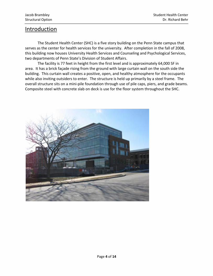
Introduction The Student Health Center (SHC) is a five story building on the Penn State campus that serves as the center for health services for the university. After completion in the fall of 2008, this building now houses University Health Services and Counseling and Psychological Services, two departments of Penn State’s Division of Student Affairs.
The facility is 77 feet in height from the first level and is approximately 64,000 SF in area. It has a brick façade rising from the ground with large curtain wall on the south side the building. This curtain wall creates a positive, open, and healthy atmosphere for the occupants while also inviting outsiders to enter. The structure is held up primarily by a steel frame. The overall structure sits on a mini‐pile foundation through use of pile caps, piers, and grade beams. Composite steel with concrete slab on deck is use for the floor system throughout the SHC.
Jacob Brambley Student Health Center Structural Option Dr. Richard Behr
Page 5 of 14
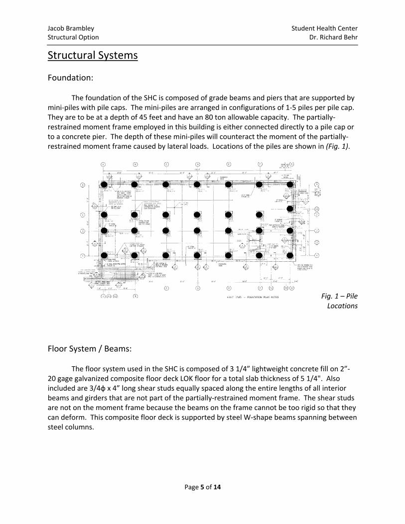
Structural Systems Foundation: The foundation of the SHC is composed of grade beams and piers that are supported by mini‐piles with pile caps. The mini‐piles are arranged in configurations of 1‐5 piles per pile cap. They are to be at a depth of 45 feet and have an 80 ton allowable capacity. The partially‐restrained moment frame employed in this building is either connected directly to a pile cap or to a concrete pier. The depth of these mini‐piles will counteract the moment of the partially‐restrained moment frame caused by lateral loads. Locations of the piles are shown in (Fig. 1).
Fig. 1 – Pile Locations
Floor System / Beams: The floor system used in the SHC is composed of 3 1/4” lightweight concrete fill on 2”‐20 gage galvanized composite floor deck LOK floor for a total slab thickness of 5 1/4". Also included are 3/4ф x 4” long shear studs equally spaced along the entire lengths of all interior beams and girders that are not part of the partially‐restrained moment frame. The shear studs are not on the moment frame because the beams on the frame cannot be too rigid so that they can deform. This composite floor deck is supported by steel W‐shape beams spanning between steel columns.
Jacob Brambley Student Health Center Structural Option Dr. Richard Behr
Page 6 of 14
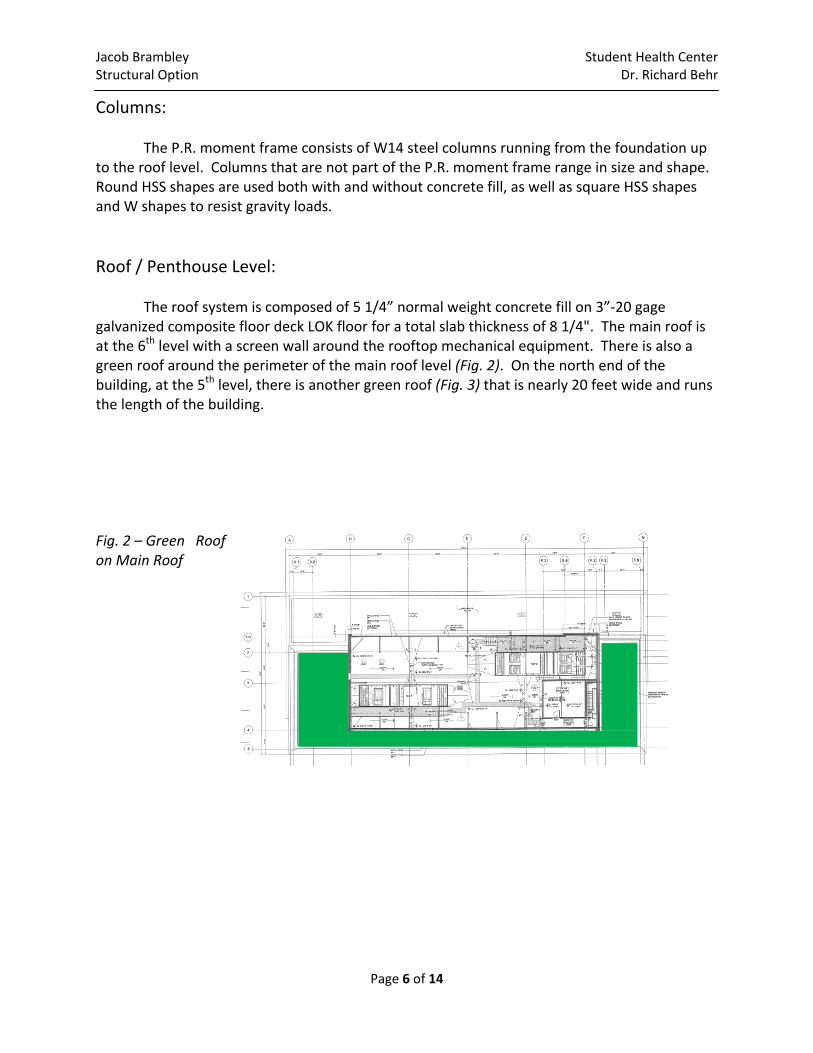
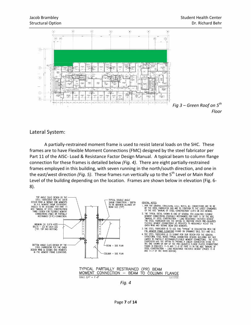
Columns: The P.R. moment frame consists of W14 steel columns running from the foundation up to the roof level. Columns that are not part of the P.R. moment frame range in size and shape. Round HSS shapes are used both with and without concrete fill, as well as square HSS shapes and W shapes to resist gravity loads. Roof / Penthouse Level: The roof system is composed of 5 1/4” normal weight concrete fill on 3”‐20 gage galvanized composite floor deck LOK floor for a total slab thickness of 8 1/4". The main roof is at the 6th level with a screen wall around the rooftop mechanical equipment. There is also a green roof around the perimeter of the main roof level (Fig. 2). On the north end of the building, at the 5th level, there is another green roof (Fig. 3) that is nearly 20 feet wide and runs the length of the building. Fig. 2 – Green Roof on Main Roof
Jacob Brambley Student Health Center Structural Option Dr. Richard Behr
Page 7 of 14
Fig 3 – Green Roof on 5th Floor
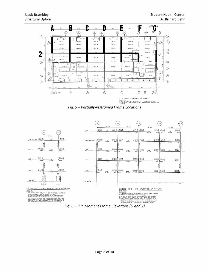
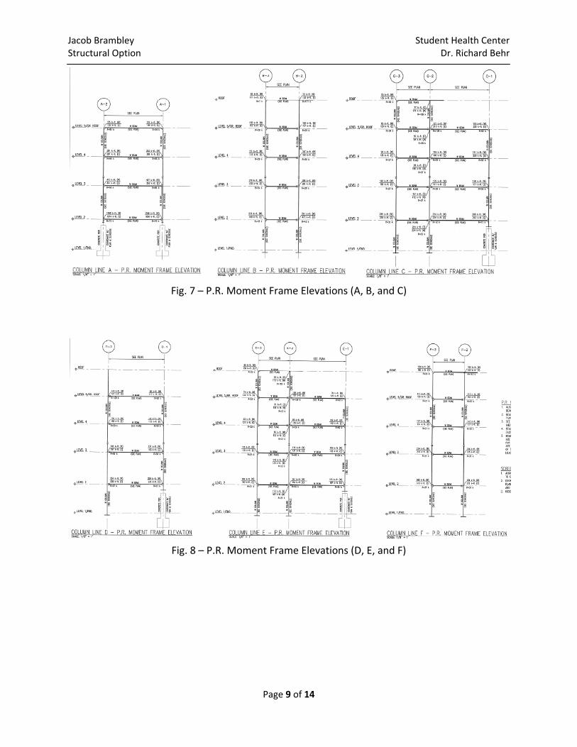
Lateral System: A partially‐restrained moment frame is used to resist lateral loads on the SHC. These frames are to have Flexible Moment Connections (FMC) designed by the steel fabricator per Part 11 of the AISC‐ Load & Resistance Factor Design Manual. A typical beam to column flange connection for these frames is detailed below (Fig. 4). There are eight partially‐restrained frames employed in this building, with seven running in the north/south direction, and one in the east/west direction (Fig. 5). These frames run vertically up to the 5th Level or Main Roof Level of the building depending on the location. Frames are shown below in elevation (Fig. 6‐8).
Fig. 4
Jacob Brambley Student Health Center Structural Option Dr. Richard Behr
Page 8 of 14
Fig. 5 – Partially‐restrained Frame Locations
Fig. 6 – P.R. Moment Frame Elevations (G and 2)
Jacob Brambley Student Health Center Structural Option Dr. Richard Behr
Page 9 of 14
Fig. 7 – P.R. Moment Frame Elevations (A, B, and C)
Fig. 8 – P.R. Moment Frame Elevations (D, E, and F)
Jacob Brambley Student Health Center Structural Option Dr. Richard Behr
Page 10 of 14
Problem Statement The existing steel frame and composite steel floor system described earlier in this proposal was constructed with no major problems and has many benefits including having a smaller effect on foundations compared to a heavy concrete frame. One downside to this steel system though, is the 29‐inch thickness of a typical floor which in turn reduces the attainable number of stories due to code height restrictions. The main reason for the construction of the Student Health Center was to create a new, larger space to house services provided in the then overcrowded Ritenour Building. If a thinner floor system was implemented, then perhaps another story could be added, increasing floor area to the maximum.
Proposed Solution A post‐tensioned floor system will be studied in detail as a means to decrease floor thickness throughout the SHC. Upon completion of Technical Report 2, it was determined that post‐tensioning would provide the smallest floor thickness, 11‐inches, compared to other systems studied. A new concrete structure will be designed along with this floor system and shear walls will be added to replace the moment frames for resisting lateral loads. Calculations pertaining to the increased self‐weight of the building on the foundations will be done to further see the effects of the new superstructure. The possibility of an additional floor will be examined and pros and cons of each system will be quantified to determine plausibility of the new design.
Solution Method For the design of the post‐tensioned slab, hand calculations will be completed using the Equivalent Frame Method (ACI 318‐08). After a floor design is finalized, column sizes will be determined using the program PCA Column and checked with hand calculations referencing ACI 318‐08. A 3D model using ETABS will be created implementing this data, as well as, loads given through ASCE 7‐05 and IBC 2006, to check that the hand calculations are accurate. Also, through use of this model, loads on columns and foundations will be revealed. Validity of the current mini‐pile foundation to resist the added dead load due to the concrete structure will be examined using these loads and a redesign will be completed if necessary. Shear walls will need to be implemented in the current layout of the building to increase effectiveness in resisting lateral loads, but also lessen impact on room area and circulation. ETABS will also be used for designing shear walls to ensure the maximum drift does not exceed ASCE 7‐05 maximum drift parameters.
Jacob Brambley Student Health Center Structural Option Dr. Richard Behr
Page 11 of 14
Breadth Topics The overhaul of the current structural system does not only impact material sizes, weights, and orientation but also impacts cost and schedule effects. Construction management issues such as material lead time and system constructability will be examined as a breadth topic. Comparisons of direct and indirect costs and construction time will be summarized upon completion of calculations. Another topic separate from the structural system that will be covered is solar shading. Difficulties with the current fabric shades wrinkling and rolling up unevenly due to their size continue. Therefore, a study of alternate systems such as light shelves and overhangs will be performed and comparisons will be drawn between these and the current shading system.
Jacob Brambley Student Health Center Structural Option Dr. Richard Behr
Page 12 of 14
Tasks and Tools Replacement Concrete System Task 1: Determine Gravity Loads Imposed on the Floor from IBC 2006 and ASCE 7‐05 Task 2: Post‐tensioned Slab Design and Detailed Tendon Layout
a) Utilize Equivalent Frame Method (ACI 318‐08) b) Design Aids
Task 3: 3D Models
a) Become familiar with ETABS software b) Model existing system using ETABS c) Model preliminary proposed system using ETABS d) Input loads determined from ASCE 7‐05 and IBC 2006
Task 4: Column Sizes
a) Determine column loads at corresponding levels b) Determine column sizes and reinforcement using PCA Column c) Check with hand calculations using ACI 318‐08
Task 5: Design Foundation
a) Determine load on foundation due to building self‐weight per 3D model data b) Check against capacity of current system c) Resize current foundation system if necessary d) Design new system if necessary
Task 6: Layout and Design of Shear Walls
a) Evaluate best location for shear walls in current building layout b) Use ASCE 7‐05 to calculate lateral loads c) Apply lateral loads to ETABS model d) Design shear walls using model e) Check against ASCE 7‐05 maximum drift limitations
Task 7: Comparison of Systems
Jacob Brambley Student Health Center Structural Option Dr. Richard Behr
Page 13 of 14
Breadth Topics Task 1: Construction Management
a) Complete a cost study of the existing and proposed system b) Determine time required to complete the existing and proposed system
a. Research typical construction times b. Review scheduling class notes
c) Research availability of post‐tension savvy contractors in the area d) Compare characteristics of each system
Task 2: Solar Shading
a) Visit site to better understand shading problems b) Research different shading systems c) Implement proposed system with the architecture d) Compare pertinent criteria
Jacob Brambley Student Health Center Structural Option Dr. Richard Behr
Page 14 of 14
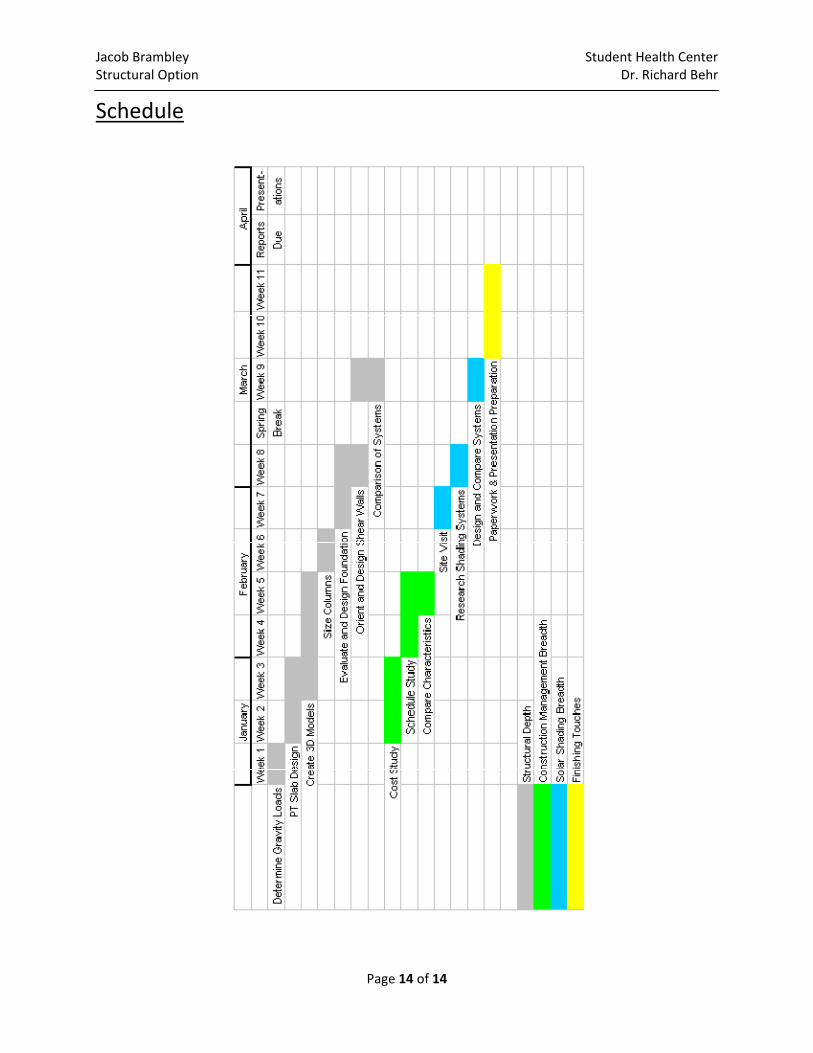
Schedule