Embed Size (px)
Citation preview

SWITCH
INDEX★Circuit For Switch
RB(RC)1, 2 Reed SwitchNotes on Switch
RB(RC)4, 5 Solid State SwitchRA1 Reed SwitchRX1 Proximity SwitchRP1, 5 Reed SwitchRP4 Solid State SwitchRE(ZE) Solid State Switch
1062 1063~1065
1066 1067 1068 1069 1070 1071 1072
SWITCH
・・・・・・・・・・・・・・・・・・・・・・・・・・・・・・・・・・・・・・・・・・・・・・・・・・・・・・・・・・・
・・・・・・・・・・・・・・・・・・・・・・・・・・・・・・・・・・・・・・・・・・・・
・・・・・・・・・・・・・・・・・・・・・・・・・・・・・・・・・・・・・・・・・・・・・・・・・・・・・・・・・・・・・・・・・・・・・・・・・・・・・・・・・・・・・・・・・・・・・・・・・・・・・・・・・・・・・・・・・・・・・・・・・・・・・・・・・・・・・・・・・・・・・・・
Switch
1061

CIRCUIT FOR SWITCH
Source Input
Sink Input(Internal Power Source)
Sink Input(External Power Source)
Sink Input(Internal Power Source)
Sink Input(External Power Source)
●For 3 wires: NPN t ype
●Protection Circuit for AC Power Source
●For 2 wires
●For 2 wires ●For 3 wires
●Protection Circuit for DC Power Source
■Cable Surge Absorbing Circuit
■Basic
■Connection to Programmable Controller (Sequence Controller)
■Contact Protection Circuit (Load Surge Absorbing Circuit)
Brown
Blue
Brown
Blue
INBrown
Blue
IN
Brown
Blue
INBlack
IN +
+ +
+ +
+ +
+ + +
-
-
-
--
-
--
---
Brown
Blue
Black
IN
Brown
Blue
Choke Coil or Resistor
Resistor R: 1 to 3 kΩCapacitor C: 0.1 μF
COM
COMCOM
COM COM
Brown
Blue
Load
Load
Load
Choke Coil :12μH~3mHResistor: 10~200Ω
Programmable Controller(Input Card)
Brown
Blue
Load
LoadBrown
Black
Blue
Switch
Switch
Programmable Controller(Input Card)
Programmable Controller(Input Card)
Programmable Controller(Input Card)
Programmable Controller(Input Card)
Switch
Switch
Switch
Switch
Switch
Switch
Switch
Switch
1062

Switch
Notes on Switch
■ Notes on design
Interlock
Switches are intended for detecting the activation position of actuators and not equipped with control functions aimed at ensuring safety such as an interlock.
Contact Protection Circuit (Measure against Surge Voltage)
A surge voltage is generated when an inductive load such as a relay and solenoid is connected. Provide a contact protection circuit. See “Switch Connection.”
Parallel Connection and Leakage Current
For activating the internal circuit, a two-wire non-contact switch has a small current running as a leakage current even when it is turned off.When the leakage current is larger than the operating current of the load, the load remains turned on.With a programmable controller (sequence controller), make sure that the “off current value” of the input unit is larger than the leakage current value.If the leakage current is larger, use a three-wire switch.When switches are connected in parallel, the leakage current is the sum total of those of the respective switches.
Serial Connection and Voltage Drop
If switches with an indicator are connected serially, a voltage drop occurs due to the internal resistance of the LEDs, etc.The voltage applied to the load side is the result of subtracting the sum total of the internal voltage drops of the respective switches from the power supply voltage value with the power supply internal resistance taken into account. There may be cases where the load does not operate even if the switches operate normally.Check the minimum operating voltage of the load.
Power Supply
When using a commercially-available switching regulator for the power supply, be sure to ground the frame ground (F.G.) terminal.When using a transformer to convert AC to DC for use, be sure to use an insulation transformer.Using an autotransformer may cause damage to the switch or power supply.If any surge is generated in the power supply, connect a surge absorber to the source to absorb the surge.
Switch Wiring Length
Long switch wiring may cause an excessive current to flow in the contact due to the inrush current generated when the switch is turned on and it may remain turned on.When the wiring length exceeds 10 m, provide a cable surge absorbing circuit. See “Switch Connection.”
Position Detection in the Middle of Stroke
When a switch is used for detecting a position in the middle of a stroke, the switch may not be turned on if the actuator operating speed is too high.Even when the switch is turned on, the relay is not turned on if the activation time of the switch is shorter than that of the relay.With a programmable controller, any signal with the activation time shorter than the input time constant cannot be recognized as a signal.In this case, reduce the actuator operating speed.
Actuator Installation Interval
A switch is activated by the magnet mounted on the actuator. If two or more actuators are brought too close to each other, the magnet of each of them may interfere to cause switch malfunction.
WARNING
1063

Switch
■ Notes on Operating Environment ■ Notes on Handling
Use in Dangerous Atmosphere
Switches do not have an explosion-proof structure. Do not use them in places where explosive gas generates dangerous atmosphere or susceptible to explosion, combustion or ignition.
Use in Strong Magnetic Field
Do not use in a strong magnetic field, which may cause malfunction or faulty operation of switches due to magnetic change of the integrated magnet or change of magnetic field distribution.
Adjacency of Magnetic Bodies
If any magnetic body such as iron is attached or brought in proximity to an actuator with a switch, the magnetic force of the integrated magnet may be lost or the magnetic field may change, rendering the switch non-functional. Take measures such as change to a nonmagnetic material. A similar condition may occur if iron powder such as chips, wear debris and welding spatters is accumulated during operation.
Operating Environment
The waterproofing property of switches conforms to the IEC IP66 (JIS C 0920 water tight type) or IP67 (JIS C 0920 immersion proof type) but environment subject to constant splashes of water may cause insulation failure. In addition, places subject to oil content of machining or other oils, acidic or alkaline liquids or organic solvents, or splashes or atmosphere of them or water vapor, may cause hardening or insulation failure of leads. Do not use in places subject to a large amount of dust.
Impact
If excessive impact is applied during operation, contact switches may malfunction.Use of non-contact switches instead can mitigate the problem but be sure to check the impact resistance value in the specification before use.
Vibration
Do not use switches in any environment subject to vibration, which may cause malfunction of or damage to switches or loosening of mounting brackets.If it is unavoidable, ensure that the vibration is not conducted.
Places subject to Surges
In and around an area subject to surges, the semiconductor devices in non-contact switches may be adversely affected. Take measures such as grounding the frame ground (F.G.) terminal of the device that generates surges.
Temperature Variation
Even within the operating temperature range, rapid variation of the ambient temperature may cause malfunction of or damage to switches.
Handling of Switches
Impact applied to switches due to falling, etc. may damage the interior of switches.
Handling of Leads
Applying excessive tension to leads may cause breaking of the leads inside the cables or damage to the interior of switches.
Switch Setting Position (Hysteresis and Operating Distance)
The distance between the point where the switch turns on by movement of the magnet and the point where it turns off by movement in the opposite direction is referred to as the hysteresis (c) and setting the switch in this range may make it susceptible to disturbance, causing unstable operation. The distance between the point where the switch turns on by movement of the magnet and the point where it turns off by further movement in the same direction is referred to as the operating distance (ℓ). The center position of these is referred to as the maximum sensitivity position and setting the switch at this position makes it resistant to disturbance, which achieves stable operation.The operating distances and hystereses provided on the pages corresponding to the respective series are reference values. Allow for variation of approximately ±40% depending on the variation between products and operating conditions. The value may more greatly vary depending on the operating conditions.
Tightening Torque for securing SwitchesTightening switch securing screws or mounting brackets with torque larger than specified may cause damage to the switches or brackets. Insufficient torque may cause displacement during operation. Keep to the specified tightening torque for mounting.
DANGER
WARNING
WARNING
OFFONOFF
Movement ofthe magnetOFF OFFON
Movement ofthe magnet
cc
1064

Switch
■ Notes on Wiring ■ Notes on Maintenance and Inspection
Power Supply Voltage
Using outside the operating voltage range or connecting switches designed for DC use to AC power supply may cause rupture or burnout.
Wiring of Leads
Before wiring, make sure that the power supply is turned off. If any switch is mounted on a moving part, provide some looseness in the cable and ensure that it is not get caught in the moving part in order to prevent stressful bending and take measures such as connection that allows replacement of the cable.When bundling together with air piping by using a spiral tube, provide some looseness in the wiring to prevent excessive force from being applied.
Connection of Load
Connecting a two-wire switch directly to power supply without connecting any load such as a relay or programmable controller for operation causes instant overcurrent, leading to rupture or burnout.
Load Short Circuit
Operating a switch with the load short-circuited causes overcurrent, leading to instant rupture or burnout.
Polarity
Switches designed for DC use have polarity. Be sure to wire correctly. The brown lead is positive (+) and the blue lead is negative (−). Wrong wiring may cause phenomena as shown below. Even if the switch is not damaged, avoid using with wrong wiring. Reverse-polarity wiring of a contact switch does not hinder switch operation but the LED is not illuminated. Reverse-polarity wiring of a non-contact switch does not damage the switch but the switch does not function. With a three-wire switch, reversing the power supply line (brown) and the output line (black) causes the switch to be damaged. Reversing the brown (positive) and blue (negative) power supply lines of a non-contact switch does not damage the switch but the switch does not function.
Insulation of Wiring
Make sure that the lead connections, extension cables and terminal block do not have insulation failure.Insulation failure may cause overcurrent in the switch, leading to rupture or burnout.
Adjacency of High-Voltage or Large-Current Cable
Do not wire in parallel with or in the same conduit as high-voltage cables or power lines.It may cause induction, leading to malfunction of or damage to the control circuit including the switch.
Check for Loosening of Screws and Brackets
Loosening of switch mounting screws or brackets may cause displacement of the switch, causing unstable operation or malfunction.Readjust the position and tighten with the specified torque.
Check for Damage to Leads
Any damaged sheath of lead indicates the possibility of insulation failure or broken wire.Replace the switch or repair the lead immediately.
WARNING WARNING
1065

RB・RC
Switch
RB(RC)1, 2/REED SWITCH
SWITCH + MODEL CODE OF FIXTURE
Dimensions
SPECIFICATIONS INTERNAL CIRCUIT OF THE SWITCH
It can be installed to the product with conventional RG1, RG2 Switch.
RB2, RC2
RC1, RC2RB1, RB2
RB1, RC1
APPLICABLE MODEL
Fill in ( ) as the series name after BE.Fill in ( ) as CT for only CTW and CTX.BE (CT)
MODEL CODE OF FIXTUREExample:BE (PPT)
For PPT6Y, CTR, PRM, PST,PRZ, the code of fixture is BF.
Example:BF (PST)
Fill in ( ) as the series name after BE.Fill in ( ) as CT for only CTW and CTX.
Example:RC2 (CT)
Conforming to EN/IEC standard
Notes: RB2 and RC2 have light windows for indicator but un-iluminative
Note1: Lead wire length of LA is changed from 5m to 3mNote2: It is not compatible with metal bracket.
(Max. sensitive position)(Max. sensitive position)
4
2
25
Indicator Light
4
2
25
4.5
φ2.8
Indicator Light
4.5
φ2.8
9
1212
Brown:+
Blue:-
ReedSwitch
Brown:+
Blue:-
ReedSwitch
Diode
LE.D
Resistance
Diode
Resistance
Note. When induction load such as Relay is used, set up a load surge protection circuit.
●Compatibility with RG switch
TypeModel TypeDirection of Cable OutletLoad VoltageLoad CurrentAverage Response TimeOpernting Tempature RangeShock Resistance
Cable
Cable LengthIndicator LightApplicationInternal Voltage DropLeakage CurrentInsulation ResistanceDielectric StrengthProtective Structure
2 Wires Reed Switch (without indicator light)RC2
Angle Outlet CableRC1 RB2RB1
Straight Outlet Cable Straight Outlet CableAngle Outlet CableDC12~24V
40mA or less1ms or less5~60℃
50MΩ or more at DC250V MEGGER (between lead wire and case)AC500V for 1 minute (bet ween lead wire and case)
φ2.8, 0.15㎜2, 2 Wire (+: Brown, -: Blue)oil-proof. bending-resistant vinyl cabtyre code
Standard: 1m Switch model code LA suffixed: 3mWithout indicator light
30G
IP67
Red LED (Iights up at ON status)**Relay. Programmable controller
0.2V or less0
2 Wires Reed Switch (with indicator light)
3~24mA
2.6V or less
PPT, PPU, PRZ, PSL, PSU, PRD, PPTNPRM, CTR, PST
GXACTW(X), CZL
FXTW
Example:RC1LA (PPT)
1066

RB・RC
Switch
RB(RC)4, 5/SOLID STATE SWITCH
Dimensions
INTERNAL CIRCUIT OF THE SWITCH
RB5, RC5
RC4, RC5RB4, RB5
RB4, RC4
(Max. sensitive position)(Max. sensitive position)
4
2
22
Indicator Light
4
2
22
4.5
φ2.8
Indicator Light
4.5
10
φ2.8
9
10
SwitchMainCircuit
Brown:+
Blue:-
Black: Output
Blue:-
SwitchMainCircuit
Brown:+
SPECIFICATIONS
Note. When induction load such as Relay is used, set up a load surge protection circuit.
TypeModel TypeDirection of Cable OutletLoad VoltageLoad CurrentConsumption Current OutputAverage Response TimeOpernting Tempature RangeShock Resistance
Cable
Cable LengthIndicator LightApplicationInternal Voltage DropLeakage CurrentInsulation ResistanceDielectric StrengthProtective Structure
3 Wires Solid State SwitchRC5
Angle Outlet CableRC4 RB5RB4
Straight Outlet Cable Straight Outlet CableAngle Outlet Cable
50mA or less10mA or less
NPN open collector1ms or less5~60℃
50MΩ or more at DC250V MEGGER (between lead wire and case)AC500V for 1 minute (bet ween lead wire and case)
φ2.8, 0.15㎜2, 2 Wire (+: Brown, -: Blue)oil-proof. bending-resistant vinyl cabtyre code
φ2.8, 0.15㎜2, 3 Wire (+: Brown, Black, -: Blue)oil-proof. bending-resistant vinyl cabtyre code
Standard: 1m Switch model code LA suffixed: 3m
50G
IP67
Red LED (Iights up at ON status)**Relay. Programmable controller
0.5V or less
2 Wires Solid State Switch
5~40mA̶̶̶̶̶̶
DC5~24VDC12~24V
3.5V or less0.5μA or less1mA or less
SWICTH
SWITCH + MODEL CODE OF FIXTURE
It can be installed to the product with conventional RG1, RG2 Switch.
APPLICABLE MODEL
Fill in ( ) as the series name after BE.Fill in ( ) as CT for only CTW and CTX.
MODEL CODE OF FIXTUREExample:BE (PPT)
For PPT6Y, CTR, PRM, PST,PRZ, the code of fixture is BF.
Example:BF (PST)
Fill in ( ) as the series name afterswitch code.Fill in ( ) as CT for only CTW and CTX.
Example:RB4 (CT)
Note1: Lead wire length of LA is changed from 5m to 3mNote2: It is not compatible with metal bracket.
●Compatibility with RG switch
PPT, PPU, PRZ, PSL, PSU, PRD, PPTNPRM, CTR, PST, AFC
GXACTW(X), CZL
FXTW
Example:RC5LA (PPT)
1067
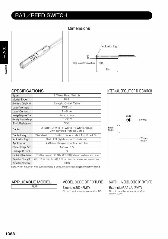
RA1/REED SWITCH
SWITCH + MODEL CODE OF FIXTURE
Dimensions
SPECIFICATIONS INTERNAL CIRCUIT OF THE SWITCH
APPLICABLE MODEL
Fill in ( ) as the series name after BD.
MODEL CODE OF FIXTUREExample:BD (FMT)FMT
Fill in ( ) as the series name afterswitch code.
Example:RA1LA (FMT)
ReedSwitch
White:+
White/Blue:-
LE.D
(Max. sensitive position)
24
φ4
9.3
Indicator Light
RA1Straight Outlet Cable
DC24V1~8mA1ms or less5~60℃30G
0.13㎜2, 2 Wire (+: White, -: White/Blue)Vinyl-covered Parallel Cords
IP66
Red LED (Iights up at ON status)**Relay. Programmable controller
Approx. 2 V0
100MΩ or more at DC500V MEGGER (between lead wire and case)AC1500V for 1 minute or AC1800V for 1 seconds (bet ween lead wire and case)
2 Wires Reed Switch
Note. When induction load such as Relay is used, set up a load surge protection circuit.
TypeModel TypeDirection of Cable OutletLoad VoltageLoad CurrentAverage Response TimeOpernting Tempature RangeShock Resistance
Cable
Cable LengthIndicator LightApplicationInternal Voltage DropLeakage CurrentInsulation ResistanceDielectric StrengthProtective Structure
Standard: 1m Switch model code LA suffixed: 5m
RA1
Switch
1068

Sunx GX-3S
RX1/PROXIMITY SWITCH
Dimensions
INTERNAL CIRCUIT OF THE SWITCH
APPLICABLE MODEL
Conforming to EN/IEC standard
AFC
419
30
φ3.8
Indicator Light
Tr
D
Zp
0V(Blue)
+V(Brown)
Output(Black)
50mA MAX-
+Relay
Main Circuit
SWITCH
SPECIFICATIONS
RX1Straight Outlet Cable
DC12~24V5~50mA
NPN open collector
5~60℃20G
φ2.6, 0.08㎜2, 3 Wire (+: Brown, Black, -: Blue)Oilproof Cabtyre Cable
IP67
Red LED (Iights up at ON status)**Relay. Programmable controller
0.4V or less0
5MΩ or more at DC250V MEGGERAC500V for 1 minute
3 Wires Proximity Switch (No-contact with built-in Amplifier)TypeModel TypeDirection of Cable OutletLoad VoltageLoad CurrentCurrent Consumption
1000HzMaximum Response FrequencyOpernting Tempature RangeShock Resistance
Cable
Cable LengthIndicator LightApplicationInternal Voltage DropLeakage CurrentInsulation ResistanceDielectric StrengthProtective Structure
3m
RX1
Switch
1069

110.5
7.5
3.5
22
(1.5)10
2
IndicatorLight
8
9 (Max. sensitive position)
RP1, 5/REED SWITCH
SWITCH + MODEL CODE OF FIXTURE
Dimensions
INTERNAL CIRCUIT OF THE SWITCH
RP5
RP1
APPLICABLE MODEL
Fill in ( ) as the series name after BD.
MODEL CODE OF FIXTUREExample:BD (JKX12)
Note: RP5 has no indicator.
JKX、JKXB、JKXN
Fill in ( ) as the series name andinner diameter after switch code.
Example:RP1LA(JKX12)
ReedSwitch
Brown:+
Blue:-
ReedSwitch
Brown:+
Blue:-
Diode
LE.D
SPECIFICATIONS
RP1 RP5Angle Outlet CableAC100V/DC24V
(AC)3~20mA/(DC)3~40mA1ms or less5~60℃30G
φ3, 0.2㎜2, 2 Wire (+: Brown, -: Blue)oil-proof. bending-resistant vinyl cabtyre code
IP67
Red LED (Iights up at ON status) Without indicator light**Relay. Programmable controller
Approx. 2 V0
100MΩ or more at DC500V MEGGER (between lead wire and case)AC1500V for 1 minute or AC1800V for 1 seconds (bet ween lead wire and case)
2 Wires Reed Switch
Note. When induction load such as Relay is used, set up a load surge protection circuit.
TypeModel TypeDirection of Cable OutletLoad VoltageLoad CurrentAverage Response TimeOpernting Tempature RangeShock Resistance
Cable
Cable LengthIndicator LightApplicationInternal Voltage DropLeakage CurrentInsulation ResistanceDielectric StrengthProtective Structure
Standard: 1.5m Switch model code LA suffixed: 5m
RP
Switch
1070

RP4/SOLID STATE SWITCH
SWITCH + MODEL CODE OF FIXTURE
Dimensions
INTERNAL CIRCUIT OF THE SWITCH
APPLICABLE MODEL
Fill in ( ) as the series name after BD.
MODEL CODE OF FIXTUREExample:BD (JKX12)JKX、JKXB、JKXN
Fill in ( ) as the series name andinner diameter after switch code.
Example:RP4LA (JKX12)
110.5
7.5
3.5
22
(1.5)10
2
8
11 (Max. sensitive position)
SwitchMainCircuit
Brown:+
Blue:-
SWITCH
IndicatorLight
SPECIFICATIONS
Angle Outlet CableDC10~30V5~70mA1ms or less5~60℃50G
φ3, 0.2㎜2, 2 Wire (+: Brown, -: Blue)oil-proof. bending-resistant vinyl cabtyre code
IP66
Red LED (Iights up at ON status)**Relay. Programmable controller
3V or less1mA or less
100MΩ or more at DC500V MEGGERAC1500V for 1 minute
2 Wires Solid State SwitchTypeModel TypeDirection of Cable OutletLoad VoltageLoad CurrentAverage Response TimeOpernting Tempature RangeShock Resistance
Cable
Cable LengthIndicator LightApplicationInternal Voltage DropLeakage CurrentInsulation ResistanceDielectric StrengthProtective Structure
Standard: 1.5m Switch model code LA suffixed: 5m
RP4
Note. When induction load such as Relay is used, set up a load surge protection circuit.
RP4
Switch
1071

RE
Switch
SwitchMainCircuit
Brown:+
Blue:-
Black: Output
Blue:-
SwitchMainCircuit
Brown:+
RE(ZE)/SOLID STATE SWITCH
SPECIFICATIONS INTERNAL CIRCUIT OF THE SWITCH
RE4, RE6
RE3, RE5
APPLICABLE MODELEHG
Note. When induction load such as Relay is used, set up a load surge protection circuit.
The overall length has become shorter. There is no change to the model No. or specification other than the overall length.
Straight Outlet Cable Angle Outlet Cable Straight Outlet Cable Angle Outlet CableDC12~24V
50mA or less (between Black and Blue)
1ms or less5~60℃
Standard: 1m For a 3-m model, replace the A at the end of the switch model No. with B.
30G
IP67
Red LED (Iights up at ON status)**Relay. Programmable controller
100MΩ or more at DC500V MEGGER (between lead wire and case)AC500V for 1 minute (bet ween lead wire and case)
RE6(LA)ZE155A(B) ZE255A(B)ZE135A(B) ZE235A(B)RE4(LA)RE5(LA)RE3(LA)
0.5V or less (DC10V or less at 20mA)50μA or less at DC24V
4.5V or less1mA or less at DC24V
10mA or less at DC24V (between Brown and Blue)
2 Wires Solid State Switch 3 Wires Solid State Switch
NPN open collector
DC5~24V4~20mA
TypeSwitch CodeModel TypeDirection of Cable OutletLoad VoltageLoad CurrentConsumption CurrentOutputAverage Response TimeOpernting Tempature RangeShock Resistance
Cable
Cable LengthIndicator LightApplicationInternal Voltage DropLeakage CurrentInsulation ResistanceDielectric StrengthProtective Structure
MODEL CODE OF FIXTURE
Order by the model No. The mounting bracket is included.Example:ZE135B
DimensionsRE5, RE6RE3, RE4
15.52
152
44.6
4.6 11.5
4
Indicator Light Indicator Light
6(Max. sensitive position) 6(Max. sensitive position)
Conforming to EN/IEC standard
φ2.6, 0.2㎜2, 2 Wire (+: Brown, -: Blue)oil-proof. bending-resistant vinyl cabtyre code
φ2.6, 0.15㎜2, 3 Wire (+: Brown, Black, -: Blue)oil-proof. bending-resistant vinyl cabtyre code
1072

RB・RC
Switch
SWITCH
APPLICABLE MODELFill in ( ) as the series name and inner diameterafter switch code.
SWITCH + MODEL CODE OF FIXTUREExample:RB6(PPT4)PPT-4
RB6, RC6 SWITCHConforming to EN/IEC standard
Dimensions
Max. SensitivePosition
Max. SensitivePosition
Brown(+)
Blue(-)
SensorMainCircuit
LoadCircuit Diagram
ExternalConnection
SPECIFICATIONS
Model Type
Model Type
Model L Dimension L Tolerance
Model L Dimension L Tolerance
ItemWiring Method
Direction of Cable OutletLoad VoltageLoad Current
Consumption Current at ONInternal Voltage DropLeakage CurrentDelay Time
Insulation ResistanceWithstand VoltageShock ResistanceVibration ResistanceProtective StructureOperation Indicator
Lead WireOpernting Tempature RangeStorage Tempature Range
Mass
Product Specifications
2 Wire System
DC10~28V4~20mA̶̶̶3.5V max0.8mA max1ms max
100MΩ min (DC500V)AC1000V (50/60Hz) 1 minute
50G9G Double Amplitude 1.5mm
IEC529 IP67Red LED Indicator illuminates at ON
φ2.6 2 Wire PVC-10~70℃-20~80℃
12g (When the lead wire length is 1m), 31g (When the lead wire length is 3m)
Straight Type L-shaped
RB6 RC6
1073

RB・RC
Switch
APPLICABLE MODELFill in ( ) as the series name and inner diameterafter switch code.
SWITCH + MODEL CODE OF FIXTUREExample:RB7LA(PPT4)PPT-4
RB7, RC7 SWITCHConforming to EN/IEC standard
SensorMainCircuit
Load
Brown(+)
Black
Blue(-)
ExternalConnection
Circuit Diagram
SPECIFICATIONS
ItemWiring Method
Direction of Cable OutletLoad VoltageLoad Current
Consumption Current at ONInternal Voltage DropLeakage CurrentDelay Time
Insulation ResistanceWithstand VoltageShock ResistanceVibration ResistanceProtective StructureOperation Indicator
Lead WireOpernting Tempature RangeStorage Tempature Range
Mass
Product Specifications
3 Wire System
DC4.5~28V50mA max
10mA max (DC24V)0.5V max0.01mA max1ms max
100MΩ min (DC500V)AC1000V (50/60Hz) 1 minute
50G9G Double Amplitude 1.5mm
IEC529 IP67Red LED Indicator illuminates at ON
φ2.6 3 Wire PVC-10~70℃-20~80℃
12g (When the lead wire length is 1m), 31g (When the lead wire length is 3m)
Straight Type L-shaped
RB7 RC7
DimensionsModel Type
Model Type
Max. SensitivePosition
Max. SensitivePosition
Model L Dimension L Tolerance
Model L Dimension L Tolerance
1074