Embed Size (px)
Citation preview

Graco, Inc. P.O. Box 1441 Minneapolis, MN 55440-1441 ©1995 Graco Inc. Form No. 321-034 6/95 Rev 2 SL Training 11/14
Technical Data Reference
Concept and Theory
1
© Graco Inc. All Rights Reserved 321123 rev 12/05
Technical Data Reference
Table of Contents
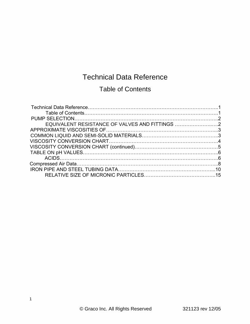
Technical Data Reference……………………………………………………………………..1 Table of Contents……………………………………………………………………….1 PUMP SELECTION…………………………………………………………………………….2 EQUIVALENT RESISTANCE OF VALVES AND FITTINGS …………………..….2 APPROXIMATE VISCOSITIES OF…………………………………………………………...3 COMMON LIQUID AND SEMI-SOLID MATERIALS………………………………………..3 VISCOSITY CONVERSION CHART………………………………………………………….4 VISCOSITY CONVERSION CHART (continued)……………………………………………5 TABLE ON pH VALUES………………………………………………………………………..6 ACIDS…………………………………………………………………………………….6 Compressed Air Data…………………………………………………………………………...8 IRON PIPE AND STEEL TUBING DATA…………………………………………………...10 RELATIVE SIZE OF MICRONIC PARTICLES……………………………………..15
2
© Graco Inc. All Rights Reserved 321123 rev 12/05
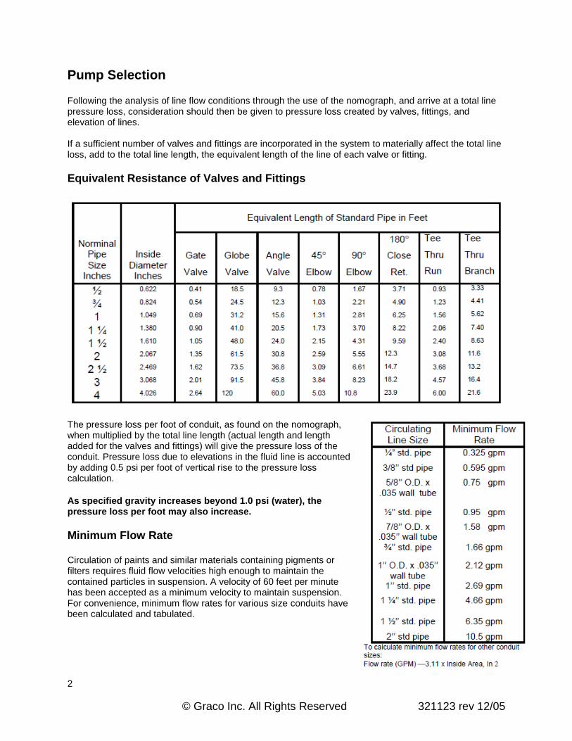
Pump Selection Following the analysis of line flow conditions through the use of the nomograph, and arrive at a total line pressure loss, consideration should then be given to pressure loss created by valves, fittings, and elevation of lines. If a sufficient number of valves and fittings are incorporated in the system to materially affect the total line loss, add to the total line length, the equivalent length of the line of each valve or fitting.
Equivalent Resistance of Valves and Fittings
The pressure loss per foot of conduit, as found on the nomograph, when multiplied by the total line length (actual length and length added for the valves and fittings) will give the pressure loss of the conduit. Pressure loss due to elevations in the fluid line is accounted by adding 0.5 psi per foot of vertical rise to the pressure loss calculation.
As specified gravity increases beyond 1.0 psi (water), the pressure loss per foot may also increase.
Minimum Flow Rate Circulation of paints and similar materials containing pigments or filters requires fluid flow velocities high enough to maintain the contained particles in suspension. A velocity of 60 feet per minute has been accepted as a minimum velocity to maintain suspension. For convenience, minimum flow rates for various size conduits have been calculated and tabulated.

3
© Graco Inc. All Rights Reserved 321123 rev 12/05
Approximate Viscosities of Common Liquid and Semi-Solid Materials
Viscosity given is indicative of the viscosity RANGE of the material in a static state. The material is extremely thixotropic and the viscosity will decrease rapidly when the material is moved, agitated, or worked in any manner.
4
© Graco Inc. All Rights Reserved 321123 rev 12/05
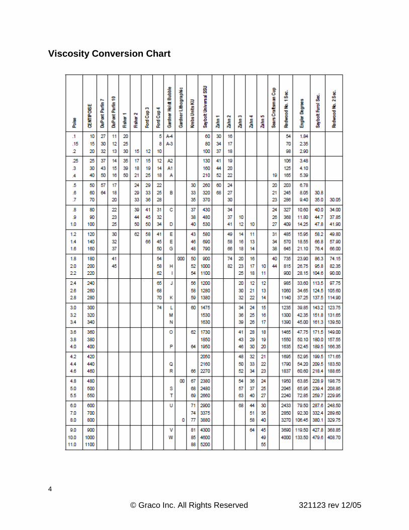
Viscosity Conversion Chart

5
© Graco Inc. All Rights Reserved 321123 rev 12/05
Viscosity Conversion Chart (continued)
All viscosity comparisons are as accurate as possible with existing information. Comparisons are made with materials having a specific gravity of one.
To extend range of only the kinematic Saybolt Universal, Redwood No. 1 and Engler Scales: Multiply by 10, the viscosities on these scales between 100 and 1000 Centistokes on the Kinematic Scale and the corresponding viscosities on the other three scales. For further extension, multiply these scales as above by 100 or a higher power of 10.
(Example: 1500 Centistokes = 150 x 10 CS695 x 10 SUS).

6
© Graco Inc. All Rights Reserved 321123 rev 12/05
Table on pH Values pH Values The acidity or alkalinity of a solution is expressed by its pH Value. A neutral solution such as water has a pH value of 7.0. Decreasing pH values from 7.0 to 0.0 indicated increasing acidity and increasing pH values from 7.0 to 14.0 indicated increasing alkalinity. Since the pH value denotes the acidity or alkalinity of a liquid, it gives some indication of the materials required in constructing a pump to handle the liquid. The pH value alone, however, is not conclusive. Many other factors must be considered. However, as an approximate
guide, Table A may be found helpful. The following tables give approximate pH values. From “Modern pH and Chlorine Control”, W.A. Taylor &
Co., by permission.
Table of Approximate pH Values

7
© Graco Inc. All Rights Reserved 321123 rev 12/05
Table on pH Values Continued
pH Factor The pH of a solution is a measurement of its hydrogen ion concentration and is indicative of its degree of acidity or alkalinity. Values of pH range from 0 to 14.0 with the middle of the range, 7.0, being neutral.
8
© Graco Inc. All Rights Reserved 321123 rev 12/05
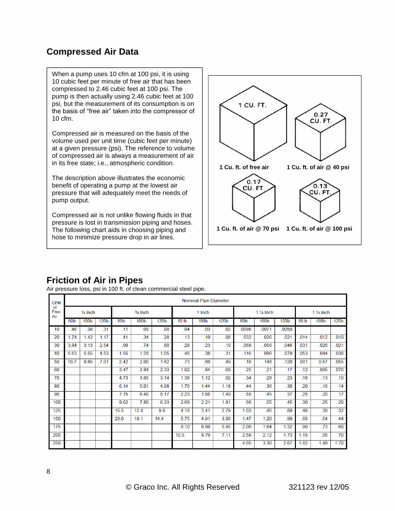
Compressed Air Data Friction of Air in Pipes Air pressure loss, psi in 100 ft. of clean commercial steel pipe.
When a pump uses 10 cfm at 100 psi, it is using 10 cubic feet per minute of free air that has been compressed to 2.46 cubic feet at 100 psi. The pump is then actually using 2.46 cubic feet at 100 psi, but the measurement of its consumption is on the basis of “free air” taken into the compressor of 10 cfm. Compressed air is measured on the basis of the volume used per unit time (cubic feet per minute) at a given pressure (psi). The reference to volume of compressed air is always a measurement of air in its free state; i.e., atmospheric condition. The description above illustrates the economic benefit of operating a pump at the lowest air pressure that will adequately meet the needs of pump output. Compressed air is not unlike flowing fluids in that pressure is lost in transmission piping and hoses. The following chart aids in choosing piping and hose to minimize pressure drop in air lines.
1 Cu. ft. of free air 1 Cu. ft. of air @ 40 psi
1 Cu. ft. of air @ 70 psi 1 Cu. ft. of air @ 100 psi

9
© Graco Inc. All Rights Reserved 321123 rev 12/05
Compressed Air Data Continued
Friction of Air in Hose (including drop through standard hose fittings)

10
© Graco Inc. All Rights Reserved 321123 rev 12/05
Iron Pipe and Steel Tubing Data Standard iron pipe is designated by its nominal inside diameter namely, 1/8”, 1/4”, 3/8”, 1/2”, 3/4”, 1”, 1 ¼”, 1 ½”, 2”, 2 ½”, 3”, etc. While errors in the early manufacture of pipe have caused inconsistencies in the smaller pipe inside diameters, the size designations have still been retained. The weights of pipe; standard, extra heavy, and double extra heavy are in common use and all three have the same outside diameter. The added wall thickness for the heavier pipe therefore reduces the inside diameter. Cast steel fittings are recommended for extra heavy pipe and forged steel fittings for double extra pipe. Steel tubing is designated by its outside diameter and its wall thickness. While it is available in a wide range of sizes, 3/8”, 1/2”, 5/8”, 7/8”, and 1” O.D., tubes are quite commonly used as fluid lines. Choice of wall thickness is practically unlimited and is governed by the working pressures encountered.
Hydraulic Tubing When power pack is located within 100 feet of pumps, the following tubing sizes will be adequate:
NOTE: When power supply is located within 100’ – 200’ of pumps, use one size larger tubing.
Steel Tubing – Maximum Working Pressure (PSI)
NOTE: The values above are based on an allowable fiber stress of 15,000 psi. For approximate bursting pressures, multiply these factors by 3.3.

11
© Graco Inc. All Rights Reserved 321123 rev 12/05
Iron Pipe and Steel Tubing Data Continued
Standard Pipe Data (Schedule 40)
Extra Heavy Pipe Data (Schedule 80)
Double Extra Heavy Pipe Data

12
© Graco Inc. All Rights Reserved 321123 rev 12/05
Coverage per Gallon for Various Film Thicknesses, Ribbon, and Bead Sizes

13
© Graco Inc. All Rights Reserved 321123 rev 12/05
Drum Specifications
Excerpts from American Standards Association, Inc.
Specifications for Metal Drum and Pails. MH 2.1-1959
through MH 2.10-1959; MH 2.11-1960 through MH
2.14-1960. Sponsor – Steel Shipping Container
Institute. Full Removable Head
Universal Drums
*Canadian 220 liter drum I.D. is 22-1/2”.
Detail of configuration for three-rolling
hoop 55-gal. drum

14
© Graco Inc. All Rights Reserved 321123 rev 12/05
Drum Specifications Continued
Tight Head Universal Drums (Non-Removable Cover)

15
© Graco Inc. All Rights Reserved 321123 rev 12/05
Filtration In a hydraulic system, filtration is the removal of contaminants from the fluid. The better the filtration, the longer the component life. In general, the filter that removes the most contaminants is the best filter. The degree of filtration is usually expressed in terms of the size (in microns) of the smallest particle that will not pass through the filter. In a hydraulic system, a 25-micron filter is adequate. A 10-micron filter is better. A 5-micron is better than a 10-micron. A 2-micron filter is better than a 5-micron filter. Selection of the ideal filter size depends not only on degree of filtration but also on the cost of filtration. Fine filtration requires almost constant maintenance. It also causes excessive pressure drops, which contribute to inefficiencies in the system. When deciding which filter is most ideal for the Graco type of hydraulic system, all these factors were considered. The result was the inclusion of a 10-micron element with each return line filter supplied as part of a hydraulic power supply. The 10-micron filter optimizes filtration and efficiency while it minimizes maintenance cost. This filter is located in the return line. It has a W.P. of 300 psi and shall never be replaced in any part of the system where it can be subjected to greater pressures; e.g., up-stream side of return line ball valve. Important note: NO valving shall ever be located on the down-stream side of the return line filter. By locating this filter in the return line, we can be assured that any contaminants remaining in the tubing after installation shall never reach the vane pump. The return line filter also eliminates the need for high cost-high pressure filters in the supply line.
Relative Size of Micronic Particles
Magnification 500 Times

16
© Graco Inc. All Rights Reserved 321123 rev 12/05
Wire Screen Data for Filters